

Page 1
Corp. 0609−L1
Service Literature
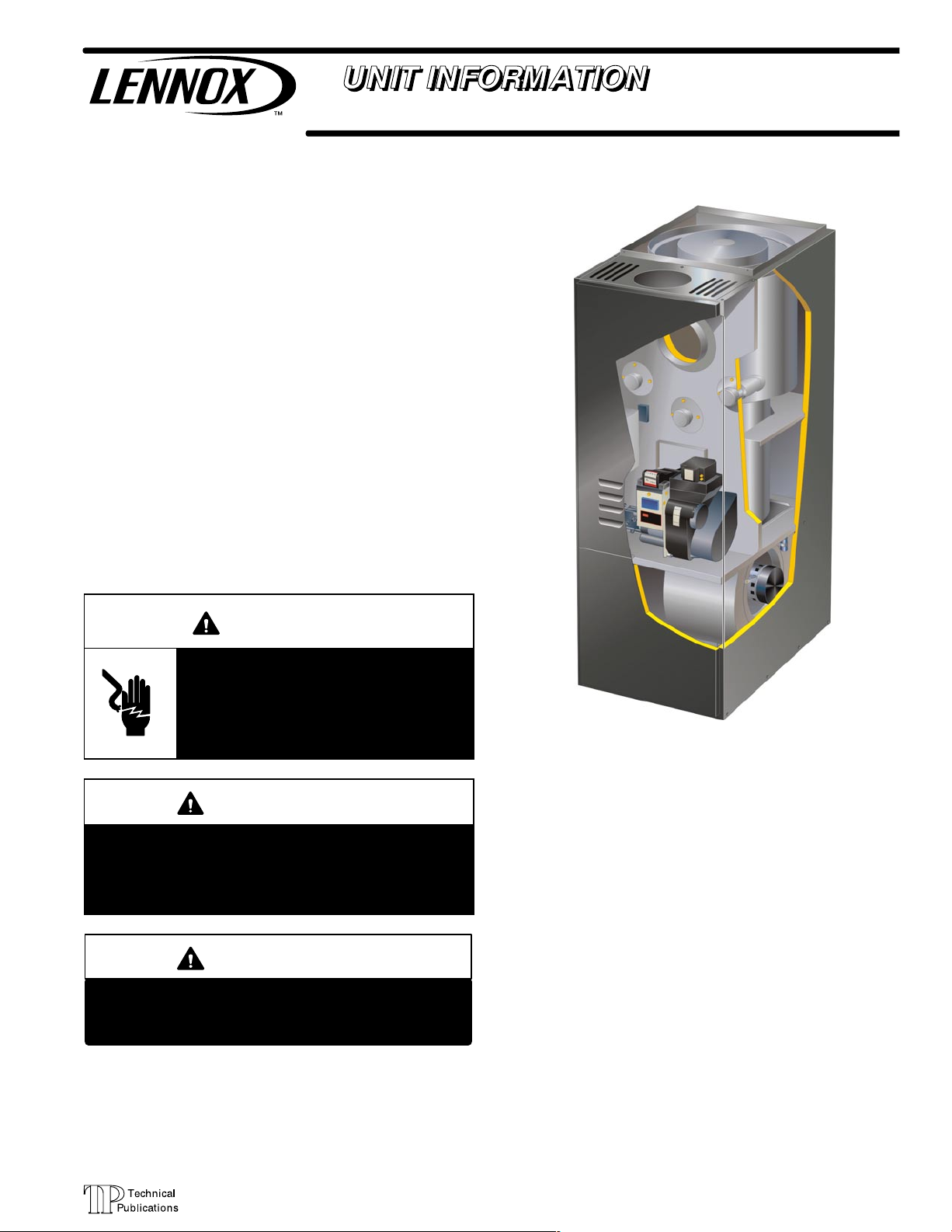
O23V SERIES UNITS
The O23V is a member of the DAVE LENNOX SIGNATUREt COLLECTION t. The O23V is an upflow oil fur-
nace equipped with a variable speed motor and manufactured with a Beckett oil burner. The O23V is available in
heating capacities of 70,000 to 154,000 Btuh (20.5 to 45.1
kW) with AFUE up to 83% and cooling applications from 1
1/2 to 5 tons (5.3 through 17.6 kW). Refer to Engineering
Handbook for proper sizing.
The drum type heat exchanger comes with strategically
placed ports allowing easy cleaning, while the oil burner
can be removed for inspection and service. The maintenance section gives a detailed description on how this is
done.
Information contained in this manual is intended for use by
experienced HVAC service technicians only. All specifications are subject to change. Procedures outlined in this
manual are presented as a recommendation only and do
not supersede or replace local or state codes.
O23V
WARNING
Electric shock hazard. Can cause injury
or death. Before attempting to perform
any service or maintenance, turn the
electrical power to unit OFF at disconnect switch(es). Unit may have multiple
power supplies.
WARNING
Improper installation, adjustment, alteration, service or maintenance can cause property damage,
personal injury or loss of life. Installation and service
must be performed by a qualified installer or service
agency.
IMPORTANT
If using programmable thermostat, be sure to use
a type of thermostat that retains its memory in
event of a power loss.
TABLE OF CONTENTS
General Page 1. . . . . . . . . . . . . . . . . . . . . . . . . . . .
Specifications Page 2. . . . . . . . . . . . . . . . . . . . . . .
Parts Arrangement Page 3. . . . . . . . . . . . . . . . . .
I Unit Components Page 3. . . . . . . . . . . . . . . . . .
II Placement and Installation Page 11. . . . . . . . . .
III Start Up Page 16. . . . . . . . . . . . . . . . . . . . . . . . . .
IV Heating Systems Service Checks Page 17. . .
V Disassembling Burner Page 19. . . . . . . . . . . . . .
VI Typical Operating Characteristics Page 21. . .
VII Maintenance Page 22. . . . . . . . . . . . . . . . . . . . .
VIII Wiring Diagrams Page 23. . . . . . . . . . . . . . . .
IX Troubleshooting Page 25. . . . . . . . . . . . . . . . . .
Page 1
© 2005 Lennox Industries Inc.
Litho U.S.A.
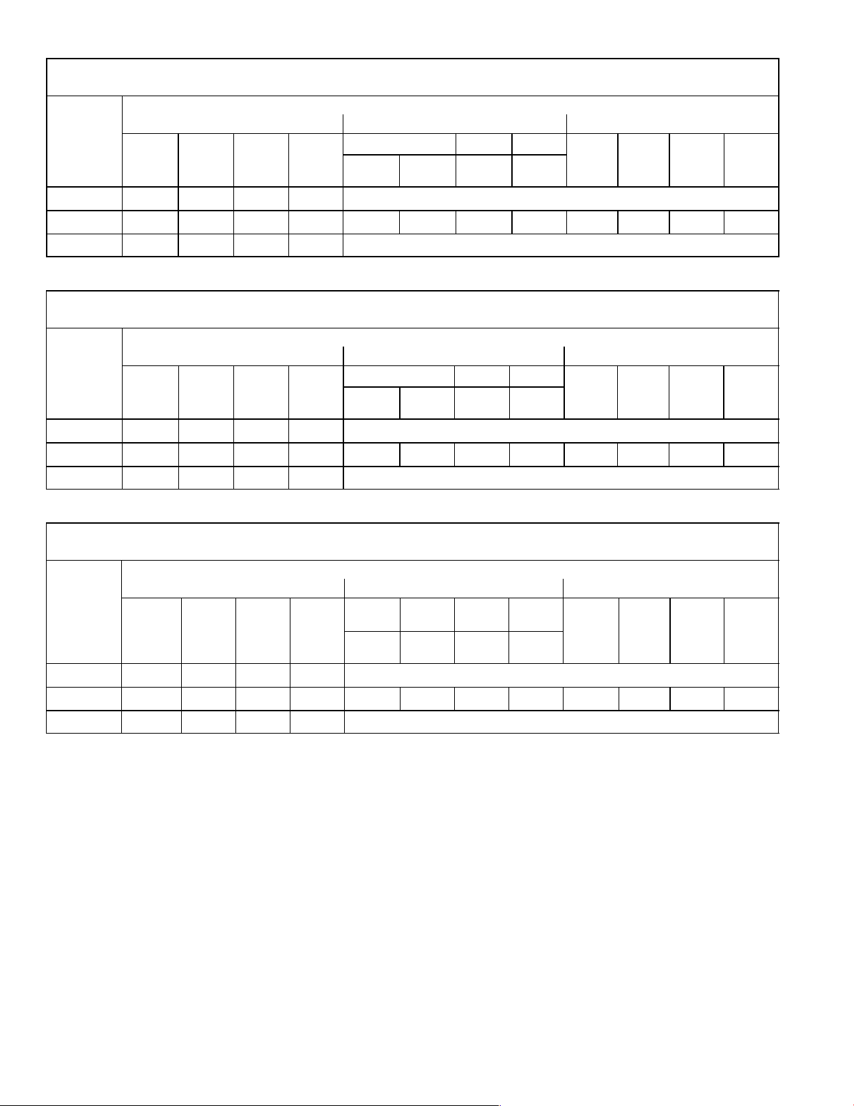
Page 2

SPECIFICATIONS
Perf
g
g
Oil
Heating
ormance
Low Fire
High Fire
Flue Connection Round − in. (mm) 6 (152) 6 (152) 6 (152)
Temperature Rise Range °F (°C)
Oil Burner
Nozzle rating − gph (L/hr) − Low
Nozzle spray angle − Low 80° hollow 80° solid 80° solid
Oil Burner Pump Pressure − psig (Pa) 100 (690) 140 (965) 140 (965)
Oil Burner Air Inlet Connection (dia.) − in (mm) 4 (102) 4 (102) 4 (102)
Blower
Data
Wheel nom. diameter x width − in. (mm)
Nominal add−on cooling − Tons (kW) 1.5 − 3 (5.3 − 10.6) 2 − 3.5 (7.0 − 12.3) 3 − 5 (10.6 − 17.6)
2
Filter
Shipping weight lbs. (kg) 1 package 225 (102) 225 (102) 275 (125)
Electrical Characteristics 120V−60hz−1ph 120V−60hz−1ph 120V−60hz−1ph
Maximum overcurrent protection (amps) 15 15 15
Model Number O23V2/3−70/90 O23V3/4−105/120 O23V5−140/154
Input − Btuh (kW)
Output − Btuh (kW)
Input
Output
1
A.F.U.E.
70,000 (20.5)
58,000 (16.7)
90,000 (26.4) 119,000(34.8) 154,000(45.1)
74,000 (21.7)
83% 81% 81%
50 − 80 (28 − 44)
105,000 (30.8) 140,000 (41.0)
85,000 (24.9) 113,000 (33.1)
97,000 (24.9) 125,000 (36.6)
50 − 80 (28 − 44) 55 − 85 (31 − 47)
.50 (1.9) .65 (2.5) .85 (3.2)
4
High
4
High 80° solid 80° solid 80° solid
4
.65 (2.5)
4
.75 (2.8)
4
1.00 (3.8)
Oil Burner Pump 1 Stage 1 Stage 1 Stage
Motor hp (W) 1/2 (373) 1/2 (373) 3/4 (560)
10 x 8 (254 x 203)
Number of filters 1 1
Size of filters − in.
mm
16 x 25 x 1 16 x 25 x 1 16 x 25 x 1
406 x 635 x 25 406 x 635 x 25 406 x 635 x 25
10 x 10 (254 x 254) 12 x 11 (305 x 280)
3
2
Optional Accessories − Must Be Ordered Extra
Half−Height Coil Case
Fits uncased C33 coils B"−width B"−width C"−width
Dimensions − in. 5 x 19−1/2 x 21−3/4 5 x 19−1/2 x 21−3/4 5 x 22−1/2 x 22−7/8
mm 127 x 495 x 552 127 x 495 x 552 127 x 572 x 581
Oil Filters
10 micron without mounting bracket 81P89 81P89 81P89
10 micron with mounting bracket 53P92 53P92 53P92
Replacement cartridge − 10 micron, 45 gph 53P93 53P93 53P93
Filter restriction indicator gauge 53P90 53P90 53P90
SignatureStatt Home Comfort Control 81M27 81M27 81M27
Two Stage Oil Pump 65A44 65A44 65A44
1
Annual Fuel Utilization Efficiency based on U.S. DOE test procedures and FTC labeling regulations. Isolated combustion system rating for non−weatherized furnaces.
2
Cleanable frame type filters. Furnished with unit in Side Filter Adaptor Kit for field installation external to the cabinet.
3
Requires return air from both sides of cabinet.
4
Nozzle must be field provided for field conversion to higher heating input.
19M11 19M11 19M12
Page 2
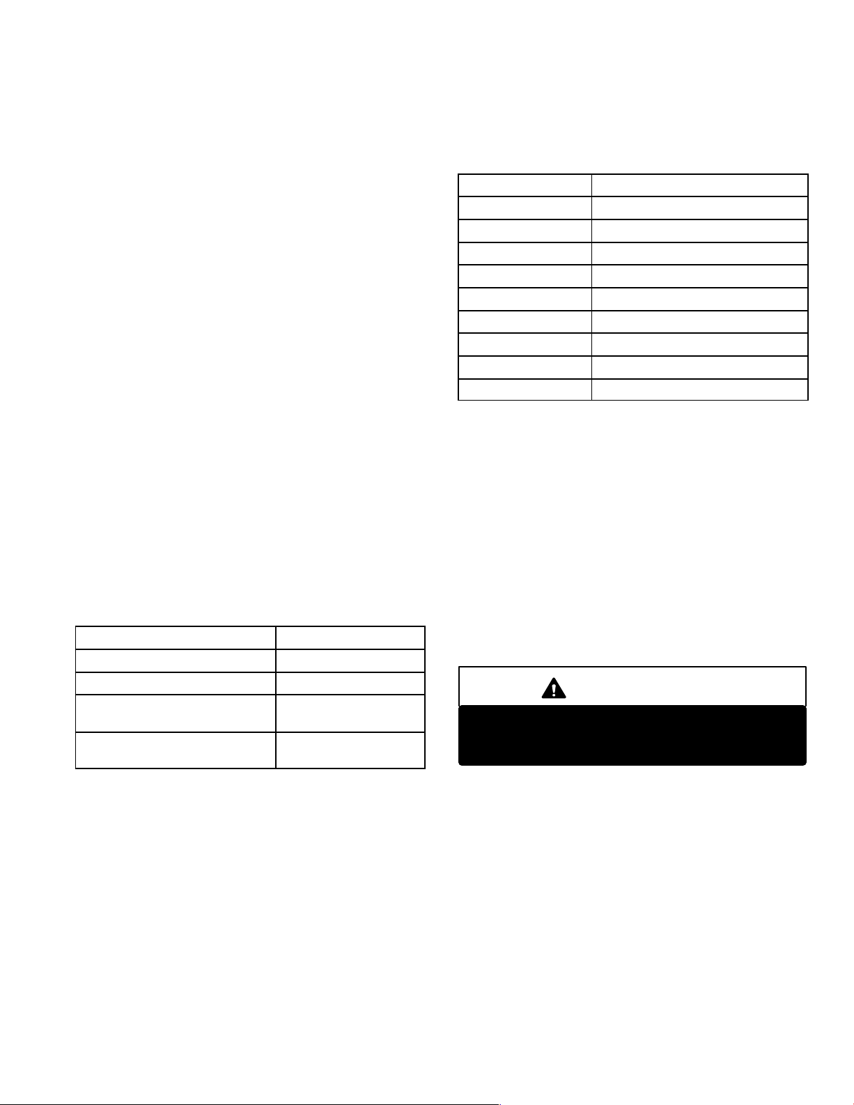
Page 3
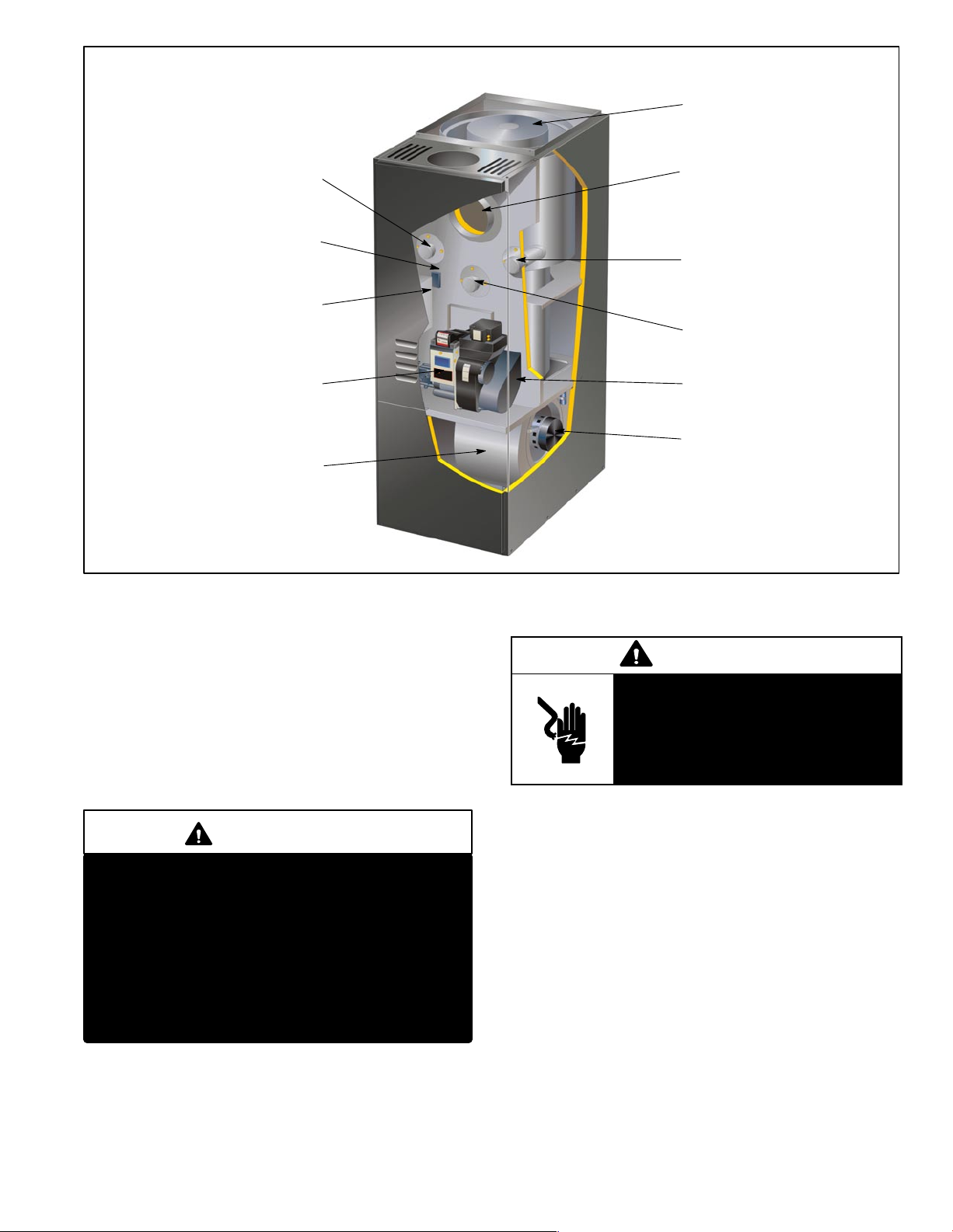
O23 GENERAL PARTS ORIENTATION
HEAT EXCHANGER
CLEAN-OUT PORT
LIMIT SWITCH
CONTROL BOX
WITH FAN
CONTROL
BECKETT
AFII BURNER
INDOOR BLOWER
I−UNIT COMPONENTS
VENT OPENING
CLEAN-OUT PORT
OBSERVATION PORT
COMBUSTION AIR INTAKE
VARIABLE SPEED
BLOWER MOTOR
FIGURE 1
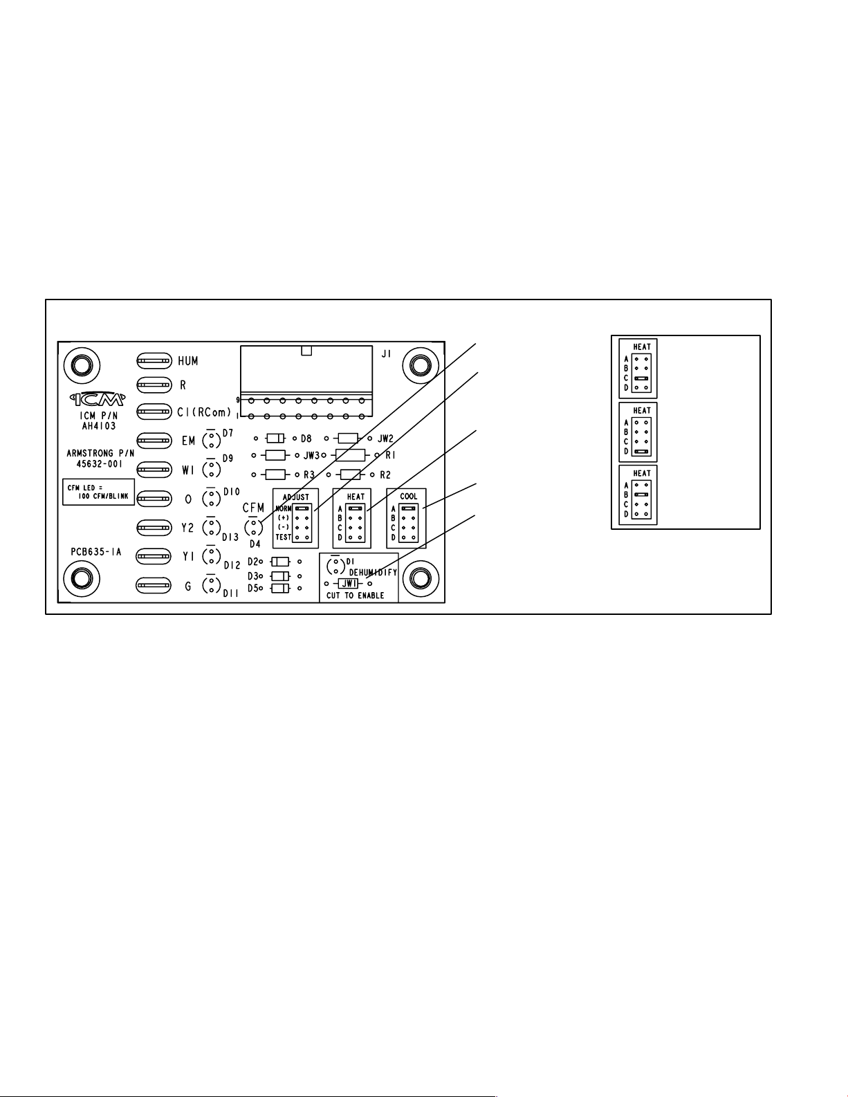
A−Blower Control Board (A54) Figure 2
General parts orientation for the O23V is shown in figure 1. The O23V control box, burner, limit switch and
clean-out ports may be accessed by removing the front
access panel. The blower can be accessed by removing
the blower access panel.
ELECTROSTATIC DISCHARGE (ESD)
Precautions and Procedures
CAUTION
Electrostatic discharge can affect electronic
components. Take precautions during unit installation and service to protect the unit’s electronic
controls. Precautions will help to avoid control
exposure to electrostatic discharge by putting
the unit, the control and the technician at the
same electrostatic potential. Neutralize electrostatic charge by touching hand and all tools on an
unpainted unit surface before performing any
service procedure.
WARNING
Electric shock hazard. Can cause
injury or death. Before attempting to
perform any service or maintenance,
turn the electrical power to unit OFF at
disconnect switch(es). Unit may have
multiple power supplies.
O23V units are equipped with a variable speed motor
which is controlled by the A54 blower control board. Blower
control board settings and operation are described in this
section.
O23V units equipped with a variable speed motor are capable of maintaining a specified CFM throughout the external static range. A particular CFM can be obtained by positioning jumpers (COOL, HEAT, and ADJUST) on the
blower control board. The HEAT and COOL jumpers are
labeled A, B, C and D; each letter corresponds with an air
volume (CFM) setting. The ADJUST jumper is labeled
Test, −, +, and Norm. The + and − pin settings are used to
add or subtract a percentage of the CFM selected in the
COOL mode only. The Test jumper is used to operate the
motor in the test mode.
Page 3
Page 4
Factory settings for the blower speed jumpers are given in
the wiring diagram. Use tables 1, 2 and 3 to determine the
correct air volume for operation in heat and cool mode.
The CFM LED located on the blower control board flashes
one time per 100 cfm to indicate selected blower speed.
For example, if the unit is operating at 1000 CFM, CFM
LED will flash 10 times.
At times, the light may appear to flicker or glow. This takes
place when the control is communicating with the motor
between cycles. This is normal operation. Read through
the jumper settings section before adjusting the jumper to
obtain the appropriate blower speed.
Blower Control Board (A54)
16−PIN PLUG
(BOARD TO MOTOR)
To change jumper positions, gently pull the jumper off the pins
and place it on the desired set of pins. Th e fo ll o w i n g sec t i o n
outlines the different jumper selections available and
conditions associated with each one (see figure 2).
After the CFM for each application has been determined, the jumper settings must be adjusted to reflect
those given in tables 1, 2 and 3. From the tables, determine which row most closely matches the desired CFM.
Once a specific row has been chosen (+, NORMAL, or
−), CFM volumes from other rows cannot be used.
Page 5 has descriptions of the jumper selections.
The variable speed motor slowly ramps up to and down
from the selected air flow during both cooling and heating demand. This minimizes noise and eliminates the
initial blast of air when the blower is initially energized.
DIAGNOSTIC LED
ADJUST
SELECTOR PINS
(Setting affect cooling
only)
HEATING SPEED
SELECTOR PINS (SEE
TABLE)
O23V−Q2/3−090
O23V−Q3/4−120
O23V−Q2/3−070
O23V−Q3/4−105
O23V−Q5−140
FIGURE 2
COOLING SPEED
SELECTOR PINS
NOTE − The JW1 resistor
must be cut to activate the
HUM terminal.
O23V−Q5−154
HEAT SPEED SELECTOR
PINS (JUMPERS)
Page 4
Page 5
ADJUST
The ADJUST pins allow the motor to run at approximately
15% higher, or approximately 15% lower, than normal
speed. Tables 1, 2 and 3 give three rows (+, NORM, and −)
with their respective CFM volumes. Notice that the normal
(NORM) adjustment setting for cool speed position C in
table 1 is 800 CFM. The + adjustment setting for that position is 920 CFM (115% of 800 CFM) and for the − adjustment setting is 680 CFM (85% of 800 CFM). After the adjustment setting has been determined, choose the
remaining speed settings from those offered in the table in
that row.
The TEST pin is available to bypass the blower control and
run the motor at approximately 70% to make sure that the
motor is operational. This is used mainly in troubleshooting. The G terminal must be energized for the motor to run.
COOL
The COOL jumper is used to determine the CFM during
cooling operation. This jumper selection is activated for
cooling when Y1 is energized. Y1 and Y2 must be jumpered for single stage cooling.
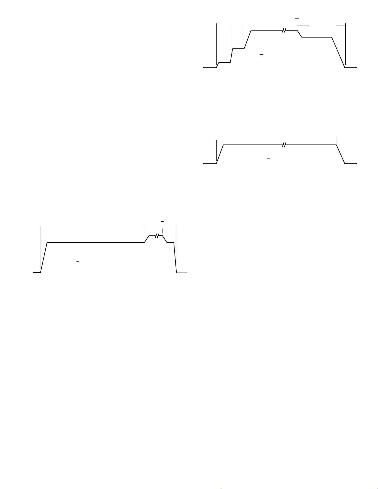
The blower motor runs at 82% of the selected air flow for
the first 7−1/2 minutes of each cooling demand. This feature allows for greater humidity removal and saves energy.
Y
7.5 minutes
82%
Y − Cool Demand Present
y − Cool Demand Satisfied
100%
y
60
sec
82%
OFFCALL
When the demand for cool is met, the blower ramps down
to 82% for 60 seconds, then turns off.
HEAT
The HEAT jumper is used to determine CFM during heat
operation only. These jumper selections are activated only
when W1 is energized.
During the heat ON delay, the blower runs at 13% CFM for
the first minute, 50% for the second minute, and full CFM
after two minutes.
W
60
sec60sec
13%
50%
100%
W − Heat Demand Present
w − Heat Demand Satisfied
w
210 seconds
82%
OFFCALL
When the demand for heat is met, the blower ramps down
to 82% for 3−1/2 minutes, then turns off.
Continuous Fan
When the thermostat is set for Continuous Fan" operation
and there is no demand for heating or cooling, the blower
control will provide 50% of the COOL CFM selected.
G
50%
G − Fan switch ON
g − Fan switch OFF
g
OFFCALL
When a continuous fan is on (G demand present), the fan
runs at 50% until switched off; there is no ramp up or off delays.
NOTE − With the proper thermostat and subbase, continuous blower operation is possible by closing the R to G circuit.
Dehumidification
The A54 blower control board (see figure 2) includes a
HUM terminal which provides for connection of a humidistat. The JW1 resistor on the blower control board must be
cut to activate the HUM terminal. The humidistat must be
wired to open on humidity rise. When the dehumidification
circuit is used, the variable speed motor will reduce the selected air flow rate by 18% when humidity levels are high.
An LED (D1) lights when the blower is operating in the dehumidification mode.
Humidification
Terminals are provided on the A15 control board for 120
volt output to operate a humidifier. The HUM" terminal is
energized when there is a call for heat. See unit wiring diagram.
Electronic Air Cleaner
Terminals are provided on A15 control board for 120 volt
output to an electronic air cleaner. The EAC" terminal is
energized when there is a call for heat, cool, or continuous
blower. See unit wiring diagram.
Page 5
Page 6
AD
ADJUST
Jumper
A
ADJUST
Jumper
A
ADJUST
Jumper
A
Jumper
Setting
+
NORM
−
AD
Jumper
Setting
+
NORM
−
TABLE 1
O23V−Q2/3−70/90 Blower Performance
0 through 0.80 in. w.g. (0 through 200 Pa) External Static Pressure Range
Jumper Speed Positions
COOL" Speed HEAT" Speed CONTINUOUS FAN" Speed
T"
A B C D A B C D A B C D
cfm L/sBcfm L/sCcfm L/sDcfm L/sAcfm L/sBcfm L/sCcfm L/sDcfm L/sAcfm L/sBcfm L/sCcfm L/sDcfm L/s
1380 565 1150 540 920 435 690 325 SAME AS NORM
1200 565 1000 470 800 380 600 285 1300 614 1100 520 1000 470 750 354 600 285 500 235 400 190 300 143
1020 480 850 400 680 320 510 240 SAME AS NORM
Do not use −90 −70
TABLE 2
O23V−Q3/4−105/120 Blower Performance
0 through 0.80 in. w.g. (0 through 200 Pa) External Static Pressure Range
Jumper Speed Positions
COOL" Speed HEAT" Speed CONTINUOUS FAN" Speed
T"
A B C D A B C D A B C D
cfm L/sBcfm L/sCcfm L/sDcfm L/sAcfm L/sBcfm L/sCcfm L/sDcfm L/sAcfm L/sBcfm L/sCcfm L/sDcfm L/s
1620 765 1380 650 1150 540 920 435 SAME AS NORM
1400 660 1200 565 1000 470 800 360 1500 713 1400 660 1300 613 1200 565 700 333 600 285 500 235 400 190
1190 560 1020 480 850 400 680 320 SAME AS NORM
Do not use −120 −105
Jumper
Setting
NORM
TABLE 3
O23V−Q5−140/154 Blower Performance
0 through 0.80 in. w.g. (0 through 200 Pa) External Static Pressure Range
Jumper Speed Positions
COOL" Speed HEAT" Speed CONTINUOUS FAN" Speed
Do not
"
A B C D A B C D A B C D
cfm L/sBcfm L/sCcfm L/sDcfm L/sAcfm L/sBcfm L/sCcfm L/sDcfm L/sAcfm L/sBcfm L/sCcfm L/sDcfm L/s
+
−
2300 1085 2070 975 1840 870 1380 650 SAME AS NORM
2000 944 1800 850 1600 755 1200 565 1850 873 1730 816 1550 732 1400 660 1000 470 900 425 800 380 600 285
1700 802 1530 720 1360 640 1020 480 SAME AS NORM
use
−154
Do not
use
−140
Page 6
Page 7
B−Burner Control (A3)
All O23V units are equipped with a burner control R7184B
manufactured by Honeywell. The burner control, along with
the matching cad cell, proves flame and controls the burner.
An LED on the control shows unit status. See table 4 for status
codes. After the cad cell closes a circuit to the burner control,
the burner control de−energizes the safety switch heater to allow the unit to operate normally. When there is a call for heat
the control performs a 2 to 6 second delay safety check. Once
this is established a 15 second pre−purge will follow. The valve
then opens for a 15 second trial for ignition. If flame is not
sensed during the 15 second trial, the control shuts down and
must be manually re−set. After three consecutive lockouts the
control goes into restricted lockout. Once flame is established
after 10 seconds of run time, the ignitor is de−energized.
If flame is lost during the heat cycle the control will shut
down the burner and begin a 60 second recycle delay. After 60 seconds the control repeats the ignition process. If
flame is lost three consecutive times during a single thermostat demand the control goes into restricted lockout.
C−Control ST9103A (A15)
Control ST9103A manufactured by Honeywell, is a
printed circuit board which monitors limit operation and
oil burner operation. Line voltage and thermostat connections are made on this control. See table 5 for terminal designations.
TABLE 5
J58 Pin #
1 Limit S10
2 L1 120V
3 24V
4 L2 Common
5 Jumpered to Pin 4
6 24V
7 Burner Motor
8 Jumpered to Pin 7
9 Limit S21 (if used)
Function
Reset button
If the control locks out three consecutive times the control
will go into restricted lockout. To reset control hold down
the reset button for 30 seconds until the LED flashes twice.
At any time the burner motor is energized, press and hold
the reset button to disable the burner. The burner will remain disabled as long as the reset button is held down and
return to operation once the button is released.
TABLE 4
LED
On Flame sensed
Off Flame not sensed
Flashing
(1/2 sec on1/2 sec off)
Flashing
(2 sec on 2 sec off)
STATUS
Lockout /
Restricted Lockout
Recycle
D−Transformer (T1)
Transformer T1 provides power to the low voltage section of the unit. Transformers are rated 40VA with a
120V primary and 24V secondary.
E−Primary Limit Control (S10)
The primary limit on all O23V units, is located on the vestibule panel. When excess heat is sensed in the heat exchanger, the limit will open. If the limit is tripped, 24 volt
power to terminal R" on the indoor thermostat is lost and the
unit shuts down but the indoor blower continues to run. The
limit automatically resets when unit temperature returns to
normal. The switch is factory set and cannot be adjusted. The
setpoint is printed on the face plate of the limit.
IMPORTANT
If using programmable thermostat, be sure to use
a type of thermostat that retains its memory in
event of a power loss.
Page 7
Page 8
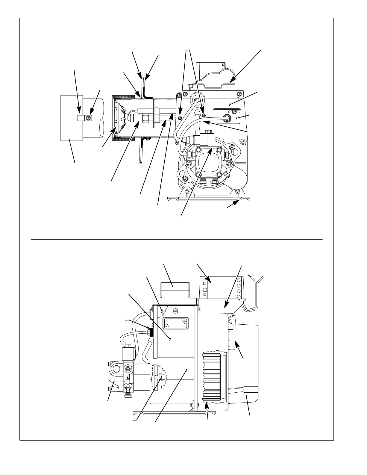
O23V BURNER PARTS ARRANGEMENT
RETAINING
CLIP
HEAD
INSULATOR
AIR TUBE
ASSY FOR
FB HEADS
1/4" HEX
HEAD SCREW
FB−HEAD
NOZZLE
ADAPTER
ELECTRODE HEAD
FLANGE
GASKET
NOZZLE LINE
ASSY.
FLANGE
ELECTRODE
ASSY
AIR TUBE
SCREWS
ELECTRONIC IGNITION
TRANSFORMER
CONNECTOR
PEDESTAL
PREMOUNTED PRE−PURGE VALVE
MAIN
HOUSING
ASSY
ESCUTCHEON
PLATE
TUBE
REAR ACCESS
DOOR ASSY
SPLINED
NUT
FUEL PUMP
COUPLING
REAR ACCESS
DOOR GASKET
MOTOR
IGNITOR
PRIMARY
CONTROL
BLOWER
WHEEL
4X4
BOX
0
3
4
5
6
7
8
AIR
ADJ.
DIAL
INLET
AIR SCOOP
FIGURE 3
Page 8
Page 9

Unit
Lennox Burner
Part Number
TABLE 6
FURNACE / BURNER SPECIFICATIONS
Burner
Model
*Initial
Air Dial
Setting
Output
Nozzle Size
(Delevan)
Pump
Pressure
Head
-70 39M85 AFII 85 3.0
-090 39M85 AFII 85 3.5
-105 39M86 AFII 85 4.0
-120 39M86 AFII 85 4.5
-140 39M87 AFII 150 6.0
-154 39M87 AFII 150 6.5
*NOTE: The initial air dial setting is provided to get unit started. The air dial setting MUST be adjusted after start-up to
achieve proper combustion.
F−Burner (Figure 3)
The O23V oil furnace uses the Beckett AFII burner. The oil
burner provides an atomized oil vapor mixed with the correct
proportion of air when it is ignited in the combustion chamber.
Oil burner minimum and maximum ratings are listed on the
unit nameplate. Proper air adjustment for these ratings is
achieved through the air adjustment dial. Set air dial to the initial air dial setting (see table 6). After start up adjust air dial to
achieve proper combustion. Remember to tighten set screw
on air dial.
The AFII burner is available in six sizes with either a single
or two stage pump. Table 6 identifies the burners used in
Lennox units.
G−Combustion Air Blower / Pump Motor (B6)
The burner is activated by the primary control. A combustion air blower is mounted on the motor shaft. The
motor shaft also connects to the direct drive oil pump
through a coupler. The burner motor turns both the combustion air blower and the oil pump. The motor operates
at 3500 RPM.
Burner motors are overload protected. In the event of
excess motor temperature or current, the overload
opens to de−energize the motor. The overload automatically resets after temperature has returned to normal.
Keep motor clean to prevent starting switch from sticking.
All AFII motors are permanently lubricated. No further oiling is
required.
57,000 BTU
(16.7 kW)
74,000 BTU
(21.7 kW)
84,000 BTU
(24.6 kW)
105,000 BTU
(30.8 kW)
112,000 BTU
(32.8 kW)
125,000 BTU
(36.6 kW)
0.50 X 80_A
0.50 X 80_A
0.65 X 80_B
0.75 X 80_B
0.85 X 80_B
1.00 X 80_B
H− Pump
The O23V units all utilize the Cleancut Fuel Unit manufactured by Beckett. This pump uses a solenoid valve to control the piston cut−on cut−off operation instead of a cone
valve and diaphram used by other conventional pumps.
The solenoid works with the R7184B Honeywell burner
control to provide cut−on cut−off operation while the burner
motor is at full speed.
At start up the pump shaft is brought to full speed before the
solenoid is energized. At this time low pressure oil
(approximately 20−25 psi) from the gear set circulates
around the pressure regulator piston which is closed and
through the open solenoid valve. The solenoid valve returns the oil to either the cover cavity (one−pipe) or return
line (two−pipe). When the solenoid valve is energized, it
closes (and remains closed while energized) blocking the
return path to the cover cavity and return line creating pressure build up in the piston cavity. The piston opens and regulates pressure and delivers pressurized oil to the nozzle.
At shutdown the solenoid valve will de−energize and open
before the pump shaft rotation stops. When the solenoid
valve opens the oil by−passes the cover cavity and return
line causing a pressure drop in the piston cavity. The piston
closes blocking oil to the nozzle while the burner motor is
running at full speed.
100 psig
(689.5 kPa)
100 psig
(689.5 kPa)
140 psig
965.3 kPa)
140 psig
965.3 kPa)
140 psig
965.3 kPa)
140 psig
965.3 kPa)
FB0
FBO
FB3
FB3
FB6
FB6
Page 9
Page 10

I−Cad Cell (R26)
Together the cad cell and the burner control prove flame.
The cad cell senses the presence of burner light (less resistance) to close a circuit to the burner control.
IMPORTANT−Burner should not be installed so it is exposed to direct sunlight or electric bulb light. If the cell
is exposed to light on start up, the burner will not operate.
Resistance for the cad cell can be checked while the burner is firing and after ignition is off. Press (1/2 second or
less) and release the reset button. The LED will flash 1 to 4
times depending on the cad cell resistance. The cad cell
resistance should read less than 1600 Ohms. See table 7.
TABLE 7
LED FLASHES
1 0 − 400Ohms
2 400 − 800 Ohms
3 800 − 1600 Ohms
4 1600 Ohms
RESISTANCE
J−Electronic Ignitor (A73)
The electronic ignitor provides the needed hot spark at the
electrodes to ignite the fuel mixture. The ignitor is a solid
state transformer with 120V primary and 20,000V secondary windings. The center of the secondary winding is
grounded. Each secondary terminal is 7000V to ground
and the total voltage between the electrodes is 14,000V.
NOTE−The leads for the solid state transformer are replaceable and are available in a kit form.
NOTE−When testing the solid state transformer, do not
use a transformer tester designed for iron magnet transformers. Damage to the tester may result.
nal leads will test for an arc. First, remove power from the
burner and disconnect the oil supply from nozzle. The cad
cell will not let the control energize the ignitor if the cad cell
senses light. Therefore remove one lead of the cad cell
from the burner control, or remove the cad cell all together
(do not forget to put back when test is complete). Place the
screwdriver blade across the terminals and slowly raise
one end of the blade off the terminal while the other remains in contact with the other terminal. There should be
an arc from terminal to the blade up to 3/4" away. If not replace the ignitor. If an arc is present then place one end of
the screwdriver on one terminal and the other end with the
grounded baseplate. Raise the blade from the baseplate
and draw an arc. Repeat with the other terminal. If the arc
from the baseplate to one terminal is weaker than the arc
from the baseplate to the other terminal, replace the ignitor.
K−Gun Assembly
The gun assembly receives oil from the oil pump and feeds
it to the nozzle. The nozzle converts liquid oil into a fog−like
mist that is discharged through the flame retention head
into the combustion chamber.
L−Flame Retention Heads
The stainless steel flame retention head (see figure 4) is
used to swirl (cone) the fog-like oil and air mixture as it
enters the combustion chamber. Three different heads
are used in the O23V. The firing rate dictates which
head is used. See table 6. The greater the FB number
the larger the slots on the head. When combustion
takes place, the flame will be cylindrical compact
shaped as a result.
FLAME RETENTION HEAD
FB3 SHOWN
Testing the Ignitor
WARNING
SHOCK HAZARD
Do not touch ignitor or any metal touching ignitor
when ignitor is energized. Can result in serious personal injury.
If the ignitor fails it will not produce a spark. Looking and
listening for the arc is a simple way to check. The most sure
way is to perform the screwdriver check. By placing the
blade of an insulated screwdriver across the ignitor termi-
FIGURE 4
Page 10
Page 11

II−PLACEMENT AND INSTALLATION
g
Make sure unit is installed in accordance with installation instructions and applicable codes.
A−Piping
The piping system and it’s components (oil filter, safety valves,
shut-off valves, etc.) must be designed to provide clean, air
free fuel to the burner.
An oil filter is required for all models. Use an oil filter of generous capacity for all installations. Install filter inside the building
between the tank shut−off valve and the burner. Locate filter
close to burner for easy servicing. The GAR−Ber 11BV−R or
equivalent filter (with the below specifications) is recommended.
Fill
Pipe
Air Vent
OIL PIPING
ONE-PIPE SYSTEM
Fuel
Unit
Oil
Tank
Shut−off
Valve
Aux
Filter
8 ft (2.4 m)
Maximum
One Pipe Lift
Maximum Firing Rate: 10GPH (38LPH)
Micron Removal: 10
Filtering Area: 500 in.
2
(3225.8 cm2)
Working Pressure: 15 PSI (103.4 kPa)
Inlet/Outlet Dimension: 3/8" (9.5 mm) NPT
Flow Rate: 45GPH (171LPH)
Fill
Pipe
Air Vent
FIGURE 5
OIL PIPING
TWO-PIPE SYSTEM
Return
Line
Fuel
Unit
Aux
Filter
Inlet
Care must be taken to ensure the restriction of the piping sy stem, plus any lift involved, does not exceed the capability of the oil pump. Each installation will be different. Use
the following guidelines when determining to use a single or
two stage pump.
When using a single−pipe system with the fuel supply level
with or above the burner (see figure 5) and a vacuum of 6"
(152 mm) Hg or below, a single stage fuel unit with a supply
line and no return line should be adequate. Manual bleeding of
the fuel unit is required on initial start up. Failure to bleed air
from the pump could result in an air lock/oil starvation condition.
NOTE−As an extra precaution, cycle heating on and off
ten times after bleeding air from the pump. This will eliminate air in the gun assembly.
When using a two pipe system with the fuel supply level
below the level of the burner (see figure 6) a single stage
fuel unit should be used in lift conditions of up to 10 feet
(3 m) and/or a vacuum of 10" (254 mm) Hg or below. A
two stage fuel unit should be used when lift exceeds 10
feet (3 m) and/or a vacuum of 10" (254 mm) Hg to 15" (381
mm) Hg. Both conditions require the use of a return line that
purges the fuel unit of air by returning it to the fuel tank. Use
table 8 when determining the run and lift for piping.
Before converting a one-pipe system to a two-pipe system the pump must be converted to a two-pipe system.
To convert the pump, install the bypass plug according
to the instructions. Notice in the two-pipe system the return line must terminate 3" (76 mm) to 4" (102 mm)
above the supply inlet. Failure to do this may introduce
air into the system and could result in loss of prime.
NOTE−If using an outside tank in cold climates a number one
fuel or an oil treatment is strongly recommended.
Oil
Tank
3"−4"
(76mm −102mm)
Return
Line
OUTSIDE TANK FUEL UNIT ABOVE BOTTOM OF TANK.
R
FIGURE 6
TABLE 8
TWO−PIPE MAXIMUM LINE LENGTH (H + R)
3450 RPM − 3 GPH (11.4 LPH)
Lift H"
Figure 5
0’
(0.0 m)
2’
(0.6 m)
4’
(1.2m)
6’
(1.8m)
8’
(2.4m)
10’
(3.0m)
12’
(3.7m)
14’
(4.3m)
16’
(4.9m)
18’
(5.5m)
3/8" (10 mm) OD
Tubing
Single
Stage
84’
(25.6 m)
73’
(22.3 m)
63’
(19.2 m)
52’
(15.8 m)
42’
(12.8 m)
31’
(9.4 m)
21’
(6.4 m)
−−−
−−−
Two
Stage
93’
(28.3 m)
85’
(25.9 m)
77’
(23.5 m)
69’
(21.0 m)
60’
(18.3 m)
52’
(15.9 m)
44’
(13.4 m)
36’
(11.0 m)
27’
(8.2 m)
−−− −−− −−−
1/2" (12 mm) OD
Single
Stage
100’
(30.5 m)
100’
(30.5 m)
100’
(30.5 m)
100’
(30.5 m)
100’
(30.5 m)
100’
(30.5 m)
83’
(25.3 m)
41’
(12.5 m)
−−−
H
Tubing
Two
Stage
100’
(30.5 m)
100’
(30.5 m)
100’
(30.5 m)
100’
(30.5 m)
100’
(30.5 m)
100’
(30.5 m)
100’
(30.5 m)
100’
(30.5 m)
100’
(30.5 m)
76’
(23.2 m)
Page 11
Page 12

B−Venting Considerations
2− The vent connector should be as short as possible to
do the job.
WARNING
Combustion air openings in front of the furnace
must be kept free of obstructions. Any obstruction
will cause improper burner operation and may result in a fire hazard or injury.
WARNING
The barometric shall be in the same atmospheric
pressure zone as the combustion air inlet to the
furnace. Deviation from this practice will cause improper burner operation and may result in a fire
hazard or injury.
CAUTION
Do not store combustible materials near the furnace or supply air ducts. The material (such as
paint, motor oil, gasoline, paint thinner, etc.) may
ignite by spontaneous combustion creating a fire
hazard.
3− The vent connector should not be smaller than the
outlet diameter of the vent outlet of the furnace.
4− Pipe should be at least 24 gauge galvanized.
5− Single wall vent pipe should not run outside or through
any unconditioned space.
6− Chimney should extend 3 feet (0.9 m) above the high-
est point where the vent passes through the roof, and 2
feet (0.6 m) higher than any portion of a building within
a horizontal distance of 10 feet (3 m).
7− The vent must not pass through a floor or ceiling. Clear-
ances to single wall vent pipe should be no less than 6"
(152 mm); more if local codes require it.
8− The vent may pass through a wall where provisions have
been made for a thimble as specified in the Standards of
the National Board of Fire Underwriters. See figure 7.
9− The vent pipe should slope upward toward the chim-
ney on horizontal run at least 1/4 inch (6 mm) to the
foot (0.3 m) and should be supported by something
other than the furnace, such as isolation hangers. See
figure 8.
WARNING
This furnace is certified for use with type L" vent.
B" vent must not be used with oil furnaces.
NOTE−Oil burning equipment may be vented into an approved masonry chimney or type L vent. (Type L vent is
similar in construction to type B gas vent except it carries a
higher temperature rating and is constructed with an inner
liner of stainless steel rather than aluminum).
Prior to installation of unit, make a thorough inspection of the
chimney to determine whether repairs are necessary. Make
sure the chimney is properly constructed and sized according to the requirements of the National Fire Protection Association. The smallest dimensions of the chimney should be
at least equal to the diameter of the furnace vent connector.
Make sure the chimney will produce a steady draft sufficient
to remove all the products of combustion from the furnace.
A draft of at least 0.04" w.c. (9.9 Pa) is required during burner operation.
1− Local building codes may have more stringent instal-
lation requirements and should be consulted before
installation of unit.
10− Extend the vent pipe into the chimney so that it is flush
with the inside of the vent liner. Seal the joint between
the pipe and the liner.
11− The furnace shall be connected to a factory built
chimney or vent complying with a recognized standard, or masonry or concrete chimney lined with a
lining material acceptable to the authority having
jurisdiction.
WALL THIMBLE
THIMBLE
COMBUSTIBLE
WALL
VENT PIPE
FIGURE 7
Page 12
Page 13

BAROMETRIC
CONTROL*
(IN EITHER
LOCATION)
CLEANOUT
*Barometric control may be installed in either vertical or horizontal
section of vent pipe within 18" (457 mm) of vent outlet of furnace.
LINER
CLEANOUT
MASONRY
CHIMNEY
FIGURE 8
12− When two or more appliances vent into a common vent,
the area of the common vent should not be less than the
area of the largest vent or vent connection plus 50% of
the areas of the additional vent or vent connection. Chimney must be able to sufficiently vent all appliances operating at the same time.
13− The vent pipe shall not be connected to a chimney vent
serving a solid fuel appliance or any mechanical draft
system.
14− All unused chimney openings should be closed.
15− All vent pipe run through unconditioned areas or outside
shall be constructed of factory built chimney sections.
See figure 9.
16− Where condensation of vent gas is apparent, the vent
should be repaired or replaced. Accumulation of condensation in the vent is unacceptable.
FACTORY−BUILT CHIMNEY
MASONRY CHIMNEY
17− Vent connectors serving this appliance shall not be
connected into any portion of mechanical draft systems operating under positive pressure.
18− Keep the area around the vent terminal free of snow,
ice and debris.
NOTE−If vent pipe needs to exit from side of cabinet, use the
cross hairs (located on either side of the unit) to cut a 6" (152
mm) round hole. Attach finishing plate (provided) with four
sheet metal screws to cover rough edges.
Combustion and Ventilation Air
(Confined and Unconfined Spaces)
Until recently, there was no problem in bringing in sufficient amounts of outdoor air for combustion −− infiltration
provided all the air that was needed and then some. In
today’s homes built with energy conservation in mind,
tight construction practices make it necessary to bring in
air from outside for combustion. Consideration must also be
given to the use of exhaust fans, appliance vents, chimneys
and fireplaces because they force additional air that could
be used for combustion out of the house. Unless outside
air is brought into the home for combustion, negative
pressure (pressure outside is greater than inside pressure) will build to the point that a down draft can occur in
the furnace vent pipe or chimney. Combustion gase s ent e r
the living space creating a potentially dangerous situation.
The importance of the previous paragraph cannot
be overstated. Users may inadvertently block fresh
air intakes after installation.
In the absence of local codes concerning air for combustion and ventilation, the following section outlines guidelines and recommends procedures for operating oil furnaces in a manner that ensures efficient and safe
operation. Special consideration must be given to combustion air needs as well as requirements for exhaust vents
and oil piping.
Combustion Air Requirements
BAROMETRIC
CONTROL*
(IN EITHER
LOCATION)
*Barometric control may be installed in either vertical or horizontal
section of vent pipe within 18" (457 mm) of vent outlet of furnace.
FACTORY
BUILT
CHIMNEY
FIGURE 9
CAUTION
Insufficient combustion air can cause headaches,
nausea, dizziness or asphyxiation. It will also
cause excess water in the heat exchanger resulting in rusting and premature heat exchanger failure. It can also cause property damage.
All oil−fired appliances require air to be used for the combustion process. If sufficient amounts of combustion air are not
available, the furnace or other appliance will operate in an inefficient and unsafe manner. Enough air must be provided to
meet the needs of all fuel−burning appliances, as well as appliances such as exhaust fans which force air out of the home.
When fireplaces, exhaust fans, or clothes dryers are used at
the same time as the furnace , much more air is required
to ensure proper combustion and to prevent a down−
draft situation. Insufficient amounts of air also cause in-
Page 13
Page 14

comple t e combustion which can result in sooting. Requirements for providing air for combustion and ventilation depend
largely on whether the furnace is installed in an unconfined or confined space.
Unconfined Space
CHIMNEY OR
OIL VENT
EQUIPMENT IN CONFINED SPACE
ALL AIR FROM INSIDE
An unconfined space is an area such as a basement or
large equipment room with a volume greater than 50 cubic feet (1.4 cubic meters) per 1,000 Btu (293 W) per
hour of the combined input rating of all appliances
installed in that space. This space also includes adjacent
rooms which are not separated by a door. Though an area
may appear to be unconfined, it might be necessary to bring in
outdoor air for combustion if the structure does no t pro v i de
enough air by infiltration. If the furnace is located in a
building of tight construction with weather stripping and
caulking around the windows and doors, follow the procedures outlined for using air from the outside for combustion and ventilation.
Confined Space
A confined space is an area with volume less than 50 cubic feet (1.4 cubic meters) per 1,000 Btu (293 W) per
hour of the combined input rating of all appliances
installed in that space. This definition includes furnace closets
or small equipment rooms.
When the furnace is installed so that supply ducts carry air
circulated by the furnace to areas outside the space containing the furnace, the return air must be handled by ducts
which are sealed to the furnace casing and which terminate
outside the space containing the furnace. This is especially
important when the furnace is mounted on a platform in a confined space such as a closet or small equipment room. Even a
small leak around the base of the unit at the platform or at the
return air duct connection can cause a potentially dangerous
negative pressure condition. Air for combustion and ventilation
can be brought into the confined space either from inside the
building or from outside.
Air from an Adjacent Space
If the confined space housing the furnace adjoins space
categorized as unconfined, air can be brought in by providing two permanent openings between the two
spaces. Each opening must have a minimum free area
of 1 square inch
(6.4 square centimeters) per 1,000 Btu
(293 W) per hour of the total input rating of all fuel−fired
equipment in the confined space. Each opening must
be at least 100 square inches (614.5 square centimeters). One opening shall be within 12" (305 mm) of the
top of the enclosure and one opening within 12" (305
mm) of the bottom (See figure 10).
OIL
FURNACE
NOTE−Each opening shall have a free area of at least 1 square inch
(6.4 square centimeters) per 1,000 Btu (293 W) per hour of the total
input rating of all equipment in the enclosure, but not less than 100
square inches
(614.5 square centimeters).
WATER
HEATER
OPENINGS
(To Adjacent Room)
FIGURE 10
Air from Outside
If air from outside is brought in for combustion and ventilation, the confined space shall be provided with two
permanent openings. One opening shall be within 12"
(305 mm) of the top of the enclosure and one within 12"
(305 mm) of the bottom. These openings must communicate
directly or by ducts with the outdoors or spaces (crawl or attic)
that freely communicate with the outdoors or indirectly
through vertical ducts. Each opening shall have a minimum
free area of 1 square inch (6.4 square centimeters) per 4,000
Btu (1172 W) per hour of total input rating of all equipment in
the enclosure (See figures 11 and 12). When communicating
with the outdoors through horizontal ducts, each opening
shall have a minimum free area of 1 square inch (6.4
square centimeters) per 2,000 Btu (586 W) per total input
rating of all equipment in the enclosure (See figure 13).
EQUIPMENT IN CONFINED SPACE
ALL AIR FROM OUTSIDE
(Inlet Air from Crawl Space and
Outlet Air to Ventilated Attic)
CHIMNEY
OR OIL
VENT
VENTILATION LOUVERS
(Each end of attic)
OIL
FURNACE
VENTILATION
LOUVERS
(For unheated
crawl space)
NOTE−The inlet and outlet air openings shall each have a free area of
at least one square inch (6.4 square centimeters) per 4,000 Btu (1172
W) per hour of the total input rating of all equipment in the enclosure.
OUTLET
AIR
WATER
HEATER
INLET
AIR
FIGURE 11
Page 14
Page 15

CHIMNEY
OR OIL
VENT
EQUIPMENT IN CONFINED SPACE
ALL AIR FROM OUTSIDE
(All Air Through Ventilated Attic)
VENTILATION LOUVERS
(Each end of attic)
OUTLET
AIR
CAUTION
Combustion air openings in the front of the furnace
must be kept free of obstructions. Any obstruction
will cause improper burner operation and may result
in a fire hazard or injury.
OIL
FURNACE
NOTE−The inlet and outlet air openings shall each have a free area of at
least one square inch (6.4 square centimeters) per 4,000 Btu (1172 W)
per hour of the total input rating of all equipment in the enclosure.
INLET AIR
(Ends 12" above
bottom)
WATER
HEATER
FIGURE 12
EQUIPMENT IN CONFINED SPACE
ALL AIR FROM OUTSIDE
CHIMNEY
OR OIL
VENT
OIL
FURNACE
NOTE−Each air duct opening shall have a free area of at least one
square inch (6.4 square centimeters) per 2,000 Btu (586 W) per hour
of the total input rating of all equipment in the enclosure. If the equipment room is located against an outside wall and the air openings
communicate directly with the outdoors, each opening shall have a
free area of at least one square inch (6.4 square centimeters) per
4,000 Btu (1172 W) per hour of the total input rating of all other equipment in the enclosure.
WATER
HEATER
OUTLET AIR
INLET AIR
FIGURE 13
When ducts are used, they shall be of the same cross−sectional area as the free area of the openings to which they
connect. The minimum dimension of rectangular air ducts
shall be no less than 3" (76 mm). In calculating free area, the
blocking effect of louvers, grilles, or screens must be considered. If the design and free area of protective covering is
not known for calculating the size opening required, it may
be assumed that wood louvers will have 20 to 25 percent free area and metal louvers and grilles will have 60
to 75 percent free area. Louvers and grilles must be
fixed in the open position or interlocked with the equipment so that they are opened automatically during equipment operation.
CAUTION
The barometric shall be in the same atmospheric
pressure zone as the combustion air inlet to the
furnace. Deviation from this practice will cause
improper burner operation and may result in a fire
hazard or injury.
Direct Connection of Outdoor Air for Combustion
The Beckett AFII burner was designed to allow for direct air
intake piping (4" [102 mm]). The maximum equivalent
length of pipe is 70 feet (21.3 m). A 90_ elbow equals 6
feet (1.8 m).
To convert the AFII burner from confined space to outside combustion air, simply remove the three screws attaching the inlet air scoop to the burner and insert 4"
(102 mm) direct air intake piping.
The use of a barometric relief placed in the intake pipe is
recommended when outdoor combustion air is directly
connected to the burner. This will allow confined space
air to be used as combustion air in the event that the
opening to the outdoor air becomes blocked. Using a
barometric relief in the intake will reduce the chance of
sooting.
CAUTION
DO NOT USE a barometric draft relief in exhaust
vent pipe if outdoor combustion air is connected
directly to the burner. The only exception are barometric draft reliefs as required by FIELD or TJERNLUND power vents.
Removal of Unit from Common Venting System
In the event that an existing furnace is removed from a venting
system commonly run with separate appliances, the venting
system is likely to be too large to properly vent the remaining
attached appliances. The following test should be conducted
while each appliance is in operation and the o ther appliances not in operation remain connected to the common venting system. If venting system has been installed
improperly, the system must be corrected as outlined in the
previous section.
Page 15
Page 16

1− Seal any unused openings in the common venting sys-
tem.
2− Visually inspect venting system for proper size and hori-
zontal pitch and determine there is no blockage or restriction, leakage, corrosion or other deficiencies which could
cause an unsafe condition.
3− Insofar as is practical, close all building doors and
windows and all doors between the space in which
the appliances remaining connected to the common venting system are located and other spaces of
the building. Turn on clothes dryers and any appliances not connected to the common venting system. Turn on any exhaust fans, such as range hoods
and bathroom exhausts, so they will operate at maximum speed. Do not operate a summer exhaust fan.
Close fireplace dampers.
4− Following the lighting instruction on the unit, place the
appliance being inspected in operation. Adjust thermostat so appliance will operate continuously.
5− Test for spillage using a draft gauge.
6− After it has been determined that each appliance re-
maining connected to the common venting system
properly vents when tested as outlined above, return
doors, windows, exhaust fans, fireplace dampers and
any other fuel burning appliance to their previous condition of use.
7− If improper venting is observed during any of the
above tests, the common venting system must be
corrected.
Horizontal Venting
HORIZONTAL VENTING
BAROMETRIC
CONTROL*
*When using indoor air,
barometric control must be
installed in the horizontal
venting system and located
within 18" (457 mm) of vent
When using direct connection,
barometric control must be
installed in the intake air pipe.
CONTROL FOR
HORIZONTAL
VENTING
outlet of furnace.
FIGURE 14
The O23V is approved for horizontal venting with the following mechanical vent systems:
Tjernlund (sideshot) #SS1C (Cat. #35E08) or Field Controls #SWG−5 (Cat. #35P08) with the CK−61 (Cat. #18N28)
control kit. Refer to manufacturers’ installation instructions
for proper installation procedures and service parts information.
Do not common vent with any other appliance when using
sidewall vent system.
Maximum permissible vent length is 70 equivalent feet
(21.3 m). Minimum length is 15 equivalent feet (4.6 m).
Calculate the equivalent vent pipe footage from the furnace to the mechanical vent system (Tjernlund or Field
Controls) by adding the straight vent pipe length and the
equivalent elbow lengths together.
The barometric draft control must be used in horizontal
(sidewall) venting system. It must be located within 18"
(457 mm) of the furnace vent outlet. See figure 14 for
barometric draft control location.
III−START-UP
A−Preliminary and Seasonal Checks
1− Inspect electrical wiring, both field and factory installed
for loose connections. Tighten as required.
2− Check line voltage. Voltage must be within range
listed on the nameplate. If not, consult the power
company and have voltage condition corrected before starting unit.
B−Heating Start-Up
FOR YOUR SAFETY READ BEFORE LIGHTING
WARNING
Do not attempt to start the burner when excess
oil has accumulated in the chamber, when the
furnace is full of vapor or when the combustion chamber is very hot.
1− Set thermostat for heating demand.
2− Turn on electrical supply to unit and open all shut-off
valves in the oil supply line to the burner..
3− Check air adjustment dial on the right side of the burn-
er (see figure 3). Set according to table 6.
4− On single line applications the oil pump must be
primed by bleeding the oil line. Open air bleed port and
start burner. A hose may be attached to direct oil into a
container. After last bubble is seen, bleed pump for 15
seconds. Hurried bleeding will impair efficient unit operation. Close port to stop bleeding. Single line installations must be absolutely air tight to prevent leaks or
loss of prime.
5− If burner stops after flame is established, repeat the
bleeding procedure.
NOTE−Air bleeding is automatic on two line applications; however, opening air bleed port will allow a faster
bleed. Run return line back to tank and terminate three to
four inches above the inlet line. Failure to bleed the system may cause air to be introduced into the system resulting in a loss of prime.
6− If the burner does not start immediately, check the
safety switch on the burner primary control.
7− If burner fails to light again, refer to the trouble-
shooting section in the back of this manual.
8− Proceed to section IV to complete start up.
Page 16
Page 17

C−Safety or Emergency Shutdown
Turn off unit power. Close all shut-off valves in the oil supply line.
D−Extended Period Shutdown
Turn off thermostat or set to UNOCCUPIED" mode.
Close all shut-off valves in the oil supply line to guarantee no
oil leaks into burner. Turn off all power to unit. All access
panels, covers and vent caps must be in place and secured.
IV−HEATING SYSTEM SERVICE CHECKS
A−Oil Piping
All oil supply piping (factory and field) must be carefully
checked for oil leaks.
B−Electrode Adjustment
When adjusting the electrode, use the AFII multipurpose
gauge (Beckett part # T−500) available from Beckett.
To set the electrode tip gap spacing, position the gauge as
shown in figure 15. Align the center mark with the nozzle
and adjust the electrodes to the two outer marks (1/8"
[3mm] to 1/16" [2mm] minimum).
To check that the nozzle is approximately centered with
the head inside diameter, align the center mark of the
gauge with the center of the nozzle orifice, as shown in
figure 17, and move the gauge from side to side at several points. Be careful not to scratch the nozzle sur-
face.
The Z" or zero dimension is important because it locates the
nozzle for the precise relationship with the combustion head.
To set the Z" dimension, position the gauge as shown in figure 17 and loosen the nozzle line electrode assembly so that
it can be moved forward or backward in the air tube until the
nozzle becomes flush against the gauge. Tighten the nozzle
line escutcheon plate screw (shown in figure 17) to lock this
Z" dimension securely.
AFII NOZZLE CENTERING
AFII ELECTRODE TIP
GAP
FIGURE 15
To position the electrode tips beyond the face of the nozzle
and above the center line, position the gauge as shown in
figure 16. Align the center mark with the nozzle and adjust
the electrodes to the AC cross marks.
AFII ELECTRODE POSITIONING
FIGURE 16
FIGURE 17
C−Pressure Check
The O23V is not equipped with a gauge port. Install a
pressure gauge in the nozzle port or bleeder port. See
figure18. The pump is factory set at 100 psig (689.5 kPa)
for the O23V−70 and 140 psig (965.3 kPa) for all other
O23V units but is adjustable . Never operate the pump in excess of 10 psig (69 kPa) above set point. Average nozzle
cutoff pressure is 80 psig (551.6 kPa). Use the same
gauge in the nozzle port to check cut−off pressure. To do
so run the burner for a short period and then turn off. The
gauge will show cutoff pressure.
Page 17
Page 18

OIL PUMP PRESSURE CHECK
Oil furnace installations also require careful inspection to
make sure the chimney is in good condition and can accommodate the products of combustion. The temperature
in unconditioned space will also affect the draft if long vent
connectors are allowed to get too cold.
**REGULATE PRESSURE
NOT SHOWN
(beside the inlet port)
**TO ADJUST PRESSURE: INSERT STANDARD SCREWDRIVER.
TURN COUNTERCLOCKWISE BELOW DESIRED PRESSURE,
THEN TURN CLOCKWISE TO SET DESIRED PRESSURE.
FIGURE 18
D−Burner Adjustment
The following instructions are essential to the proper operation of O23V series oil furnaces. To prevent sooting, these
instructions must be followed in sequence:
NOTE−All w.c. measurements are below atmospheric
pressure (negative readings).
CAUTION
Failure to adjust burner properly will result in
sooting.
1−Draft
This test should be taken at the outlet of the vent pipe from
the furnace and the barometric damper. Generally a 1/4" (6
mm) hole will need to be drilled for the draft gauge to be
inserted into the vent connector.
A minimum of 0.03" w.c. (7.5 Pa) draft must be established without the burner in operation. With the burner in
operation, the draft should be 0.04" w.c. (9.9 Pa) to 0.05"
w.c. (12.4 Pa). This is VERY critical to the flame retention
head burners.
2−Overfire Draft
This test should be taken with the burner in operation.
Remove the screw from the center of the center inspection port. Insert your draft gauge into the hole.
A reading of the overfire draft should be 0.02" w.c. (5.0 Pa)
less than the reading found in the vent connector. If a positive reading is seen at this point, the secondary heat exchanger may be sooted or to much air may be entering
into the heat exchanger from the combustion fan. Adjustments to the combustion fan can be made using the air
adjustment dial.
3−Smoke Test
The smoke test should be taken at hole drilled in step 1.
Using a smoke test gun adjust the air inlet shutter so that
you will have just a trace of smoke. Somewhere between a 0 and #1 smoke. This is the starting point. Do
not stop here. After the smoke test take a CO sample.
C.S.A. requires no more than 400ppm. However, a
properly installed unit under normal operating conditions should not read more than 50ppm.
4−CO2 Test
Again to be taken at the vent connector pipe. With the
unit firing at a trace of smoke, test for percentage of CO
in the vent gas.
From the results of this test, a window of operation" will be
determined. This window of operation establishes some tolerance. The tolerance the installer builds in provides room
within the set-up for those things which might affect combustion. Those things which might affect combustion can
then do so without causing the unit to start sooting/smoking.
Things which might affect combustion include a nozzle going bad, draft that changes during different climatic conditions, dirty oil, dirt obstructing the air inlet, etc.
To build in a window of operation," set up the burner to be
2% less in CO
CO
, adjust the air inlet shutter to increase the air and drop
2
the CO
to 10%.
2
. For example, if you find a reading of 12%
2
5−Retest the Smoke
With a drop in the CO2 and increase in the air you should
see that the smoke has returned to 0.
2
Page 18
Page 19

6−Retest the Overfire Draft
This test serves to confirm that you have not increased the air
too much. Again you do not want a positive pressure at the
test port. It should still be 0.02" w.c. (5.0 kPa) less than the
draft from the vent connector. You may need to increase the
stack draft by adjusting the barometric damper.
NOTE − A negative heat exchanger is important in the
event of a breach (crack) in the heat exchanger. The
negative pressure along with positive pressure from
the indoor blower will pull or blow air in to the heat exchanger preventing combustion products or soot into
the air stream.
7−Stack Temperature
Take a stack temperature reading in the vent connector pipe.
Subtract the room air temperature from the stack temperature.
This will give you the net stack temperature. Using efficiency
charts provided in most CO
analyzers you can tell at what ef-
2
ficiency the furnace is operating.
V−DISASSEMBLY PROCEDURES
Use the following procedures to access and disassemble the
burner or blower if service to either is needed.
BURNER REMOVAL
First, loosen three nuts which
attach burner to vest panel.
nuts
Next, rotate burner counterclockwise
on slots then pull toward you.
FIGURE 19
1−Removing Ignition Transformer
1− Remove all four screws located on the side of the
ignition transformer. See figure 20.
2− Lift the ignition transformer straight up. Do
not hinge back. Porcelain isolators may break if
hinged back.
NOTE−When testing the solid state transformer, do not
use a transformer tester designed for iron magnet transformers. Damage to the tester may result
WARNING
Electric shock hazard. Can cause injury
or death. Before attempting to perform
any service or maintenance, turn the
electrical power to unit OFF at disconnect switch(es). Unit may have multiple
power supplies.
A−Disassembling Burner
The burner assembly is attached to the vestibule panel by
three nuts. Slots are provided in the mounting flange for
removing the burner assembly from the vestibule. By
loosening the nuts and by turning the whole burner assembly counterclockwise (figure 19), the entire burner assembly will come out of the furnace. There is adequate wire
to remove the burner without disconnecting wires. Once removed, just turn the burner around in the vest panel area.
NOTE−Before disassembling any part of the burner, turn
off power and oil supply to the burner.
IGNITION TRANSFORMER
IGNITION
TRANSFORMER
SCREWS
SCREW TO OPEN
ACCESS DOOR
SCREWS
ACCESS
DOOR
FIGURE 20
Page 19
Page 20

2−Removing Cad Cell
1− Loosen the screw to the back access door until door
opens. See figures 20 and 21.
2− The cad cell will be located on the right side of the
chassis wall hung on a bracket. See figure 21.
GUN ASSEMBLY
3− Remove by loosening the screw on the bracket.
4− Disconnect the leads from the primary control termi-
nal strip.
CAD CELL
CAD CELL
SCREW
ACCESS
DOOR
Remove
both nuts
Gun
Assembly
FIGURE 22
4−Removing Oil Pump
1 − Shut off oil.
2 − Disconnect supply line at pump and oil line at gun
assembly. On 2 pipe system remove return line.
3 − Loosen two bolts on sides of pump securing pump
to blower housing. See figure 23.
4 − Detach pump and motor shaft coupler from pump.
OIL PUMP
SUPPLY LINE
BOLT
INLET
FIGURE 21
3−Removing Nozzle Gun Assembly
1− Loosen the screw to the back access door until door
opens. See figures 20 and 21.
2− Remove flare fitting nut on oil line at pipe adjusting
plate located on outside of blower housing.
3− Remove nut connecting oil line to gun assembly oil
line. See figure 22.
4− Remove gun assembly from air tube.
5− Remove transformer leads.
NOTE−When reinstalling gun assembly, check and
set position and Z" dimension as shown in figure
17.
NOTE−When reconnecting gun assembly oil line, make
sure flat side of nut goes first.
BOLT
FIGURE 23
5−Removing Combustion Air Blower
1− Turn off power. Disconnect supply line at pump and
oil line at gun assembly as shown in figure 23.
2− If motor and blower wheel are to be removed away
from the burner, disconnect motor wiring harness
from the primary control. If the motor and blower
wheel only need to be removed to check and clean,
there is adequate wire in the motor wiring harness
without disconnecting.
3− Loosen two bolts securing motor to blower hous-
ing. Key hole slots are provided for easy removal.
See figure 24.
4− Loosen allen set screw holding the blower wheel
onto the motor shaft and remove blower wheel.
Page 20
Page 21

COMBUSTION AIR MOTOR & WHEEL
BOLT
B−Temperature Rise
Temperature rise for O23V units depends on unit input
blower speed, blower horsepower and static pressure.
The blower speed must be set for unit operation within the
range of AIR TEMP. RISE °F" listed on the unit rating plate.
To Measure Temperature Rise:
MOTOR AND WHEEL
BOLT
FIGURE 24
NOTE−When reinstalling blower wheel use the AFII multipurpose gauge (Beckett part # T−500) to space the distance from the back of the blower wheel to the face of the
motor (1/16" [2 mm]).
B−Removing Indoor Blower
1− Turn off electric power to furnace.
2− Remove blower access door.
3− Remove two screws located in the front blower rails.
4− Pull blower forward enough to disconnect the motor
leads.
5− Pull blower assembly out and place to the side.
VI−TYPICAL OPERATING CHARACTERISTICS
A−Blower Operation and Adjustment
NOTE− The following is a generalized procedure and
does not apply to all thermostat controls.
1− Blower operation is dependent on thermostat con-
trol system.
2− Generally, blower operation is set at thermostat sub-
base fan switch. With fan switch in ON position, blower
operates continuously. With fan switch in AUTO position,
blower cycles with demand.
3− In all cases, blower and entire unit will be off when line
voltage is disconnected.
1. Place plenum thermometers in the supply and return air
plenums. Locate supply air thermometer in the first horizontal run of the plenum where it will not pick up radiant
heat from the heat exchanger.
2. Set thermostat to highest setting.
3. After plenum thermometers have reached their
highest and steadiest readings, subtract the two
readings. The difference should be in the range
listed on the unit rating plate.
C−Blower Speed
Blower speed selection is accomplished by changing the
jumpers on the blower motor control board. Page 5 explains
blower speed adjustments.
D−External Static Pressure
1. Measure tap locations as shown in figure 25.
2. Punch a 1/4" (6 mm) diameter hole in supply and return air plenums. Insert
manometer hose flush with
inside edge of hole or insulation. Seal around the
hose with permagum. Connect the zero end of the manometer to the discharge (supply) side of the system. On ducted systems, connect the other end of
manometer to the return duct as above. For systems
with non−ducted returns, leave the other end of the
manometer open to the atmosphere.
3. With only the blower motor running and the evaporator coil dry, observe the manometer reading.
4. Pressure drop must not exceed 0.5" W.C. (124.3 Pa).
5. Seal around the hole when the check is complete.
STATIC PRESSURE
TEST
MANOMETER
OIL UNIT
FIGURE 25
Page 21
Page 22

VII−MAINTENANCE
C−Annual Burner Maintenance
CAUTION
Never operate unit with access panels to the
blower compartment off or partially open.
A−Filters
If throw-away type filters are used, check monthly and
replace when necessary to assure proper furnace operation. Replace filters with like kind and size.
If reusable type filters are used, check monthly and clean with
water and mild detergent when necessary. When dry, they
should be sprayed with filter handicoater prior to reinstallation.
Filter handicoater is RP Products coating no. 418 and is available as Lennox part no. P-8-5069 or cat no. 30165.
B−Cleaning Heat Exchanger
NOTE−Use papers or protective covering in front of furnace while cleaning furnace.
Cleaning the heat exchanger is made easier with a heat
exchanger clean-out kit ABRSH380 (catalog # 35K09)
available from Lennox.
1− Remove vent pipe from furnace.
2− Remove locking screws and caps from cleanout
tubes. Remove vent access elbow.
3− Using a long spiral wire brush, sweep down the outer
drum of the heat exchanger. Then using the hose attachment, vacuum out loose debris.
4− Remove locking screw and cap from the observation
tube and with the spiral wire brush, reach upward toward the rear of the heat exchanger to clean out the
crossover tube.
NOTE− Do not attempt to clean the combustion chamber.
It can be easily damaged.
5− Replace the cleanout caps and vent access elbow.
Make sure locking screws are secure.
6− Brush out and vacuum the vent outlet area of the outer
drum and replace vent pipe.
7− Clean around the burner, blower deck and vestibule
area.
IMPORTANT
The homeowner should be instructed to have
burner inspected at the beginning of every heating season.
1− Replace the oil supply line filter.
2− Remove and clean the pump strainer if applicable.
3− Replace the nozzle with an equivalent nozzle.
4− Check the pump pressure when changing nozzle.
5− Clean and inspect the electrodes for damage, re-
placing any that are cracked or chipped.
6− Clean the combustion head of all lint and soot.
7− Inspect the transformer cables and connectors.
8− Remove and clean the cad cell.
9− Clean the blower wheel and the air control of any lint.
10− Check all wiring for secure connections or insulation
breaks.
11− Re-adjust the burner as described in section IV of this
manual.
D−Supply Air Blower
1- Disconnect power to unit.
2- Check and clean blower wheel.
3- Motors are prelubricated for extended life; no further lu-
brication is required.
E−Vent Pipe
The vent pipe should be inspected annually. Remove and
clean any soot or ash found in the vent pipe. Vent pipe deteriorates from the inside out and must be disconnected in order to check thoroughly. Inspect pipe for holes or rusted
areas. Inspect the vent control device and replace if found
defective. Check for tightness and to make sure there is no
blockage or leaks.
F−Electrical
1- Check all wiring for loose connections.
2- Check for correct voltage at unit (unit operating).
3- Check amp-draw on blower motor.
Motor Nameplate_________Actual_________
4- Check to see that heat is operating.
Page 22
Page 23

VIII−WIRING DIAGRAMS AND SEQUENCE OF OPERATIONS
8
5
1
3
6
7
2
1. When disconnect is closed, 120V is routed to control
board (A15). The control board feeds line voltage to transformer (T1).
2. When there is a call for heat, W1 of the thermostat energizes W of the A15 board with 24VAC.
3. A15 energizes combustion air inducer B6 (burner motor)
assuming primary limit (S10) is closed.
4. Burner control A3 energizes the electronic ignitor causing a 20,000VAC spark . Pump valve (L35) is delayed
for a 15 second pre−purge. The pre−purge is followed by
a 15 second trial for ignition.
5. After the pre−purge and trial for ignition (30 seconds)
voltage passes through contactor K1 the energizing the
indoor blower B3 on heating speed.
6
7
4
5
8
6. When heat demand is satisfied, W1 of the thermostat
de-energizes W of the ignition control. Combustion air
inducer B6 is de−energized. The indoor blower ramps
down to 82% for 3 1/2 minutes then shuts off.
7. When there is a call for cooling, Y1 of the thermostat energizes Y and G of the A15 board with 24VAC.
8. A15 energizes relay K2. When K2 contacts close, the indoor blower B3 energizes on cooling speed.
9. When cooling demand is satisfied, Y1 of the thermostat
de-energizes Y and G. The condensing unit shuts off immediately and the indoor blower ramps down to 82% for
60 seconds then shuts off.
6
Page 23
Page 24

1
3
2
TJERNLUND HORIZONTAL VENTING SYSTEM (SIDESHOT) OPERATION SEQUENCE:
1. When 1K2 closes, 120VAC is routed through the relay/timer, electronic ignitor (A73), and the limit switch.
2. The relay/timer energizes the venter motor.
3. After the venter motor establishes a draft, the N.O. fan proving switch closes completing the circuit to the burner motor.
1
2
3
FIELD CONTROL HORIZONTAL VENTING SYSTEM OPERATION SEQUENCE:
1. When 1K2 closes, 120VAC is routed through the relay.
2. The relay energizes the venter motor.
3. After the venter motor establishes a draft, the N.O. fan proving switch closes, completing the circuit to the burner motor and electronic ignitor (A73).
Page 24
Page 25

IX−TROUBLESHOOTING
Burner failure or improper unit operation can be caused by various conditions. Often the problem can be solved by a logical process of checks and eliminations. The following pages lists a few common problems along with the s o lution s . Car e f ully c h eck
the most obvious items first before proceeding to more involved procedures.
COMMON CHIMNEY VENTING PROBLEMS
Problem: Top of chimney lower
than surrounding objects.
Solution:Extend chimney above
all objects within 10 feet
(3 meters).
Problem: Chimney cap or ventilator.
Solution: Remove.
Problem:Obstruction in chimney. Obstruction can be found by
light and mirror reflecting conditions in chimney.
Solution: Use weight to break and dislodge.
Problem: Joist projecting into chimney.
Can be found by lowering a light on an extension cord.
Solution: Must be handled by a
competent brick contractor.
Problem: Break in chimney lining. Can be
found by Smoke test-build smudge fire blocking off other opening and watching for smoke
to escape.
Solution: Must be handled by a
competent brick contractor.
Problem: Collection of soot at narrow space in the
flue opening. Can be found by lowering light on
extension cord.
Problem: Clean out with weighted brush or bag of
loose gravel on end of line.
Problem: Loose−seated pipe in flue
opening. Detected by smoke test.
Solution: Leaks should be eliminated
by cementing all pipe openings.
Problem:Coping restricts opening.
Solution:Make opening as large as
inside of chimney.
Problem: Offset. Can be found
by lowering light on extension.
Solution: Change to straight or
long offset.
Problem: Two or more openings
into same chimney. Can be found
by inspection.
Solution: The least important
opening must be closed
FIRE-
PLACE
DAMPER
FIREPLACE
Problem: Smoke pipe extends into chimney.
Detected by measurement of pipe from within or observation of pipe by means of a lowered light.
Solution: Length of pipe must be reduced to allow end
of pipe to be flush with inside of tile.
Problem: Failure to extend the length of
the flue partition down to the floor. Detected by inspection or smoke test.
Solution: Extend partition to floor level.
ASH DUMP
Problem:Loose fitting clean−out door.
Detected by smoke test.
Solution: Close all leaks with cement.
Page 25
Page 26

Troubleshooting: Fan board operating sequence
thermostat circuit
detector circuit
Action System Response
Thermostat calls for heat.
(W terminal is energized.)
Thermostat ends call for heat.
(W terminal is de−energized.)
Burner fails to light. Oil primary control locks out within lockout timing (timing depends on oil primary control).
Established flame fails. Burner motor is de−energized and oil primary control goes into recycle mode.
Limit switch opens. Oil primary control shut off the burner.
Limit switch closes. If there is a heat demand, A15 control board energizes oil primary control, initiating burner light
Blower control board closes oil primary control T−3T connections.
Ignition system and oil primary control start the furnace. Oil flows as long as oil primary control
senses flame.
Burner motor energized and heat fan on delay timing begins. When timing is complete, the
circulating fan is energized at heat speed and warm air is delivered to the controlled space.
Oil primary control is de−energized, terminating the burner cycle.
Heat fan off delay timing begins. When timing is complete, circulating fan is de−energized.
Blower control board returns to standby mode (oil primary control and circulating fan are off).
Burner motor is de−energized.
If the fan off delay is longer than the recycle timing, the heat fan continues to run through the
next trial for ignition.
Circulating fan is energized immediately.
A15 control board opens oil primary control T−3T connections.
Circulating fan runs as long as limit stays open.
off.
Troubleshooting: Burner fails to start
Source Procedure Causes Correction
Thermostat Check thermostat settings. Thermostat in OFF or
COOL
Thermostat is set too low Turn thermostat to higher temperature.
Safety
Overloads
Power Check furnace disconnect
Thermostat Touch jumper wire across
CAD Cell Disconnect the flame
Check burner motor,
primary safety control, &
auxiliary limit switch.
switch & main disconnect.
thermostat terminals on
primary control. If burner
starts, then fault is in the
thermostat circuit.
detector wires at the
primary control. If the
burner starts, fault is in the
detector circuit.
.
.
Burner motor overload
tripped
Primary control tripped on
safety
Auxiliary limit switch tripped
on safety
Open switch Close switch.
Blown fuse or tripped circuit
breaker
Broken or loose thermostat
wires
Loose thermostat screw
connection
Dirty thermostat contacts Clean contacts.
Thermostat not level Level thermostat.
Faulty thermostat Replace thermostat.
Flame detector leads are
shorted
Flame detector exposed to
light
short circuit in the flame
detector
Switch to HEAT.
Push reset button pump motor.
Reset primary control.
Reset auxiliary limit.
Replace fuse or reset circuit breaker.
Repair or replace wires.
Tighten connection.
Separate leads.
Seal off false source of light.
Replace detector.
table continued on next page
Page 26
Page 27

Troubleshooting: Burner fails to start
p
power is going to the
p
indicates power to the
Source CorrectionCausesProcedure
Primary Control Place trouble light between
the black and white leads.
No light indicates that no
ower is going to the
control.
Place trouble light between
the orange and white leads.
No light indicates faulty
control.
Burner Place the trouble light
between the black and
white leads to the burner
motor. No light indicates
that no power is getting to
the motor.
Place trouble light between
the black and white leads to
the blower motor. Light
indicates
motor and burner fault.
ower to the
Primary or auxiliary control
switch is open
Open circuit between
disconnect switch and limit
control
Low line voltage or power
failure
Defective internal control
circuit
Blown fuse Replace the fuse.
Binding burner blower
wheel
Seized fuel pump
Defective burner motor Replace the motor.
Check adjustment. Set the maximum setting.
Jumper terminals; if burner starts, switch is faulty,
replace control.
Trace wiring and repair or replace it.
Call the power company.
Replace the control.
Turn off power and rotate the blower wheel by
hand. If seized, free the wheel or replace the fuel
pump.
Troubleshooting: Burner starts, but no flame is established
Source Procedure Causes Correction
Oil Supply Check tank gauge or use dip stick. No oil in tank Fill tank.
Coat dip stick with litmus paste and
insert into bottom of tank.
Listen for pump whine. Tank shut−off valve closed Open valve.
Oil Filters & Oil
Line
Oil Pump Install pressure gauge on pump
Nozzle Disconnect ignition leads. Observe
Listen for pump whine. Oil line filter is plugged
Open bleed valve or gauge port.
Start the burner. No oil or milky oil
indicates loss or prime.
and read pressure. −70/90 should
not be less than 100 psi. −105/120,
−140/154 should not be less than
140 psi.
the oil spray (gun assembly must
be removed from unit). Inspect the
nozzle for plugged orifice or carbon
build−up around orifice.
Water in oil tank If water depth exceeds 1 inch,
pump or drain water.
Replace filter cartridges.
Kinks or restriction in oil line
Plugged fuel pump strainer
Air leak in oil supply line Locate and correct leak.
Pump is partially or completely
frozen. No pressure and the motor
locks out on overload.
Coupling disengaged or broken − no
pressure
Fuel pressure too low Adjust psi.
Nozzle orifice plugged
Nozzle strainer plugged
Poor or off center spray
Repair or replace oil line.
Clean strainer or replace pump.
Tighten all connections.
Replace pump.
Re−engage or replace coupling.
Replace nozzle with the same size,
spray angle, and spray type.
table continued on next page
Page 27
Page 28

Troubleshooting: Burner starts, but no flame is established
g
figure 15
g
excessive drag
p
the primary control
,
run, this may be due to
pp
g,
Source CorrectionCausesProcedure
Ignition
Electrodes electrodes and leads.
Ignition
Transformer
Burner Motor Motor does not come up to speed
Remove gun assembly and inspect
Connect ignition leads to the
transformer. Start burner and
observe spark. Check line voltage
to transformer primary.
and trips out on overload. Turn off
power and rotate blower wheel by
hand to check for binding or
excessive dra
.
.
Fouled or shorted electrodes Clean electrode leads.
Dirty electrodes and leads
Eroded electrode tips Clean electrode tips and reset the
Improper electrode gap spacing
Improper position of electrode tips
Damaged Transformer Leads Replace Transformer
Cracked or chipped insulators Replace electrode.
Cracked or burned lead insulators Replace electrode leads.
Low line voltage Check voltage at power source.
Burned out transformer windings. Replace the transformer.
No spark or weak spark Properly ground the transformer
Low line voltage Check voltage at power source.
Pump or blower overloading motor Correct cause of overloading.
Faulty motor Replace motor.
gap and correct position tips. See
ure 15.
fi
Correct cause of voltage drop or
call the power company.
case.
Correct cause of voltage drop or
the call power company.
.
Troubleshooting: Burner starts and fires, but lock out on safety
Source Procedure Causes Correction
Poor Fire After burner fires,
immediately jumper across
flame detector terminals at
rimary control.
the
S If burner continues to
this may be due to
run
poor fire. Inspect fire.
Flame Detector
Primary Control
S If fire is good, fault is in
the flame detector.
Check detector circuit.
S If burner locks out on
safety, fault is in the primary control.
.
Unbalanced fire Replace nozzle
Too much air − −lean short fire Reduce combustion air − check
combustion.
Too little air − − long dirty fire Increase combustion air − check
combustion.
Excessive draft Adjust barometric damper for correct draft.
Too little draft or restriction Correct draft or remove restriction.
Dirty cad cell face Clean cad cell face.
Faulty cad cell − exceeds 15000 hms Replace cad cell.
Loose or defective cad cell wires Secure connections or replace cad cell
holder and wire leads.
Primary control circuit defective Replace primary control.
Page 28
Page 29

Troubleshooting: Burner starts and fires, but short cycles (too little heat)
)
white leads). If burner
i
limit
in the power source.
y jump
immediately jumper
terminals at the primary
S If
burner continues to
g,
(does not lock out on
Source Procedure Causes Correction
Thermostat Check thermostat. Heat anticipator set too low Correct heat anticipator setting.
Vibration at thermostat Correct source of vibration.
Limit Control Connect voltmeter between
line voltage connections to
primary control (black &
white leads
cycles due to power
nterruption, it is cycling on
.
limit.
Power If voltage fluctuates, fault is
in the power source.
Recheck voltage at the
power source.
. If burner
Thermostat in the path of a warm air
draft
Dirty furnace air filters Clean or replace filter.
Burner running too slow Increase blower speed to maintain proper
Blower motor seized or burned out Replace motor.
Blower bearings seized Replace bearings and shaft.
Blower wheel dirty Clean blower wheel.
Blower wheel in backward Reverse blower wheel.
Wrong motor rotation Replace with properly rotating wheel.
Restrictions in return or supply air
system
Adjustable limit control set too low Reset limit to maximum stop setting.
Loose wiring connection Locate and secure connection.
Low or fluctuating line voltage Call power company.
Shield thermostat from draft or relocate.
temp. rise.
Correct cause of restriction.
Troubleshooting: Burner starts and fires, but loses flame and lock out on safety
Source Procedure Causes Correction
Poor Fire After burner fires,
immediatel
across flame detector
terminals at the primary
control.
S
run (does not lock out
of safety), fault may be
poor fire. Inspect fire.
Flame Detector
S If fire is good, check for
fault in flame detector
circuit.
Oil Supply
S If burner loses flame
(does not lock out on
safety), fault is in the
fuel system.
Listen for pump whine Restriction in oil line Clear restriction.
er
Unbalanced fire Replace nozzle
Too much air − − lean short fire Reduce combustion air − check combustion.
Too little air − − long dirty fire Increase combustion air − check combustion.
Excessive draft Adjust barometric damper for correct draft.
Too little draft or restriction Correct draft or remove restriction.
Dirty CAD cell face Clean CAD cell face.
Faulty CAD cell − − exceeds 15000
hms
Loose or defective cad cell wires Secure connections or replace cad cell holder
Pump loses prime − air slug Prime pump at bleed port
Pump loses prime − air leak in
supply line
Water slug in line Check oil tank for water (over 1 inch) pump or
Partially plugged nozzle or nozzle
strainer
Plugged fuel pump strainer Clean strainer or replace pump.
Cold oil − outdoor tank Change to number 1 oil.
Replace CAD cell.
and wire leads.
Check supply line for loose connections and
tighten fittings.
drain out water.
Replace nozzle.
Page 29
Page 30

Troubleshooting: Burner runs continuously (too much or too little heat)
control
Burner turns off: ther
smoke
Low CO
2
less than
ture is more than
Too much heat
Source Procedure Causes Correction
Thermostat Disconnect thermostat
wires at the primary
control.
.
S Burner turns off: ther-
mostat circuit faulty.
Primary
control
Combustion combustion for CO2,
S Burner not turning off:
primary control faulty.
Check burner
stack temperature, and
smoke
S Low CO
less than
2
10%.
S High smoke reading
more than a trace.
S High stack tempera-
ture is more than
550_F Net.
Oil Pressure oil pressure.
Inspect fire and check
Shorted or welded thermostat contacts Repair or replace the thermostat.
Stuck thermostat bimetal Clear obstruction or replace thermostat.
Thermostat not level Level thermostat.
Shorted thermostat wires Repair short or replace wires.
Thermostat out of calibration Replace thermostat.
Thermostat in cold draft Correct draft or relocate the thermostat.
Defective primary control Replace the defective primary control.
Too little heat
Too much combustion air Reduce combustion air.
Air leaks into heat exchanger around
inspection door, etc.
Excessive draft Adjust barometric draft control for correct draft.
Incorrect burner head adjustment Correct burner head setting.
Dirty or plugged heat exchanger Clean heat exchanger.
Insufficient draft Increase draft.
Incorrect burner head adjustment Correct burner setting.
Too little combustion air Increase combustion air.
Too little blower air Increase blower speed to maintain proper
Blower belt too loose (if equipped) Tighten blower belt.
Dirty or plugged heat exchanger Clean heat exchanger.
Dirty blower wheel Clean blower wheel.
Dirty furnace air filters Clean or replace filter.
Restricted or closed registers/dampers Readjust registers or dampers.
Partially plugged or defective nozzle Replace nozzle.
Oil pressure too low: See table 6. Increase oil pressure. See table 6.
Correct cause of air leak.
Readjust burner.
temperature rise.
Page 30
 Loading...