

Lennox O23 SERIES Installation Instructions Manual

INSTALLATION
E 2002 Lennox Industries Inc.
Dallas, Texas, USA
INSTRUCTIONS
O23 SERIES UNITS
OIL UNITS
504,626M
38152A059
01/04
Supersedes 04/02
Table of Contents
General 1. . . . . . . . . . . . . . . . . . . . . . . . . . . . . . . . . . . . .
Shipping & Packing 1. . . . . . . . . . . . . . . . . . . . . . . . . .
Requirements 4. . . . . . . . . . . . . . . . . . . . . . . . . . . . . . . .
O23 Unit Dimensions 2. . . . . . . . . . . . . . . . . . . . . . . . . . .
O23 Start−Up & Performance Check List 2. . . . . . . . .
O23 Unit Parts Arrangement 3. . . . . . . . . . . . . . . . . . . . .
O23 Oil Burner Parts Arrangement 3. . . . . . . . . . . . . . . .
Locate & Level the Unit 5. . . . . . . . . . . . . . . . . . . . . . . .
Setting the Unit 5. . . . . . . . . . . . . . . . . . . . . . . . . . . . . . .
Unit Adjustments 5. . . . . . . . . . . . . . . . . . . . . . . . . . . . .
Venting 6. . . . . . . . . . . . . . . . . . . . . . . . . . . . . . . . . . . . .
Flue Connections 10. . . . . . . . . . . . . . . . . . . . . . . . . . . .
Supply & Return Air Plenums 11. . . . . . . . . . . . . . . . .
Oil Supply Line & Filter Connections 12. . . . . . . . . . .
Leak Check 13. . . . . . . . . . . . . . . . . . . . . . . . . . . . . . . . .
Electrical Wiring 13. . . . . . . . . . . . . . . . . . . . . . . . . . . . .
Unit Start-Up & Adjustments 15. . . . . . . . . . . . . . . . . .
Service 16. . . . . . . . . . . . . . . . . . . . . . . . . . . . . . . . . . . .
Troubleshooting 17. . . . . . . . . . . . . . . . . . . . . . . . . . . . .
Litho U.S.A.
RETAIN THESE INSTRUCTIONS
FOR FUTURE REFERENCE
WARNING
Do not store or use gasoline or other flammable vapors and liquids in the vicinity of this or any other appliance.
WARNING
Improper installation, adjustment, alteration, service, or maintenance can cause injury or property
damage. Refer to this manual. For assistance or
additional information, consult a qualified installer
or service agency.
CAUTION
When venting this appliance, keep vent terminal free
of snow, ice and debris.
General
These instructions are intended as a general guide and do
not supersede local codes in any way. Only qualified technicians can install and service the Lennox Elite® Series
O23 oil furnaces. In Canada, refer to CSA B139 for recommended installation procedures. Consult authorities who
have jurisdiction before installation.
CAUTION
Never burn garbage or paper in the heating system.
Never leave papers near or around the unit.
Shipping & Packing List
1− Assembled oil furnace
1− Barometric draft control
1− Side exhaust pipe collar
1− Direct intake collar (AFII burner units only)
Check the components for shipping damage. If you find any
damage, immediately contact the last carrier.
01/04
*2P0104*
Page 1
504,626M
*P504626M*

O23 Unit Dimensions − Inches (mm)
O23Q2/3-70/90
3/4
(19)
3/4
(19)
C
D
SUPPLY
AIR
OPENING
TOP FLUE
OUTLET
FLUE OUTLET
CENTERING HOLE
(Field Fabricate
ELECTRICAL INLET
(Right Side Only)
OIL PIPING INLET
(Left Side Only)
OPT. OUTDOOR
COMBUSTION
CENTERING HOLE
(Field Fabricate
1-1/2
Right Side only)
(38)
1-1/4
(32)
Model No. A B C D E
O23Q2/3-70/90
O23Q3/4-105/120
O23Q5-140/154
TOP VIEW
SIDE
Either Side)
FLUE
CONNECTION
(On Heat
Exchanger)
AB
54
(1372)
AIR FLOW
AIR INLET
1-1/2
(38)
22
14
(356)
(559)
RETURN AIR
OPENING
(Either Side)
23-1/2
(597)
2 (51)
22
(559)
RETURN AIR
E
RETURN AIR
SIDE VIEW FRONT VIEW
in. 19-1/2 30-5/8 18 19-5/8 16
mm 495 778 457 498 406
in. 22-1/2 33-1/8 21 22-1/8 18
mm 572 841 533 562 457
O23 Start−Up & Performance Check List
Job Name
Job Location
Installer
Unit Model No.
HEATING SECTION
Electrical Connections Tight?
Supply Voltage
Blower Motor H.P.
Blower Motor Lubrication O.K.?
Piping Connections Tight?
Burner Model No.
Oil Pump Pressure [recommended min. 100 psig for −70;
min. 140 psig for all other units )]
Blower Motor Amps
All Valves Open?
Serial Number
Job No.
Serial No.
Page 2
Date
City
City
State
State
Serviceman
PROPER DRAFT
Draft Reading (recommended .03−.04 inches w.c.)
% CO2 (recommended 12%)
Flue Connections Tight?
Fan Control Setting (maximum 130_ F)
(55_C)
Temperature RiseFan Control Cutout
Filter Clean & Secure?
Vent Clear?
THERMOSTAT
Calibrated? Heat Anticipator Properly Set? Level?

O23 Unit Parts Arrangement
clean-out port
limit switch
control box
with fan control board
Beckettr
AFII burner
heat exchanger
flue opening
clean−out port
observation
port
combustion air intake
blower motor
indoor blower
O23 Oil Burner Parts Arrangement
RETAINING
CLIP
HEAD SCREW
HEAD
INSULATOR
FLANGE
GASKET
AIR TUBE
ASSY FOR
FB HEADS
1/4" HEX
FB−HEAD
NOZZLE
ADAPTER
NOZZLE LINE
ELECTRODE HEAD
ASSY.
FLANGE
ELECTRODE
ASSY
AIR TUBE
SCREWS
PREMOUNTED OIL−DELAY VALVE
PEDESTAL
Figure 1
ELECTRONIC IGNITION
TRANSFORMER
REAR ACCESS
DOOR GASKET
REAR ACCESS
DOOR ASSY
MAIN
HOUSING
ASSY
SPLINED
NUT
ESCUTCHEON
PLATE
CONNECTOR
TUBE
FUEL PUMP
COUPLING
Figure 2
capacitor
IGNITOR
MOTOR
PRIMARY
CONTROL
BLOWER
WHEEL
4X4
BOX
0
3
4
5
6
7
8
AIR
ADJ.
DIAL
INLET
AIR SCOOP
Page 3

Requirements
IMPORTANT
WARNING
Product contains fiberglass wool.
Disturbing the insulation in this product during
installation, maintenance, or repair will expose you
to fiberglass wool dust. Breathing this may cause
lung cancer. (Fiberglass wool is known to the State
of California to cause cancer.)
Fiberglass wool may also cause respiratory, skin,
and eye irritation.
To reduce exposure to this substance or for further
information, consult material safety data sheets
available from address shown below, or contact your
supervisor.
Lennox Industries Inc.
P.O. Box 799900
Dallas, TX 75379−9900
WARNING
Improper installation, adjustment, alteration, service
or maintenance can cause property damage, personal injury or loss of life. Installation and service must
be performed by a qualified installer or service
agency.
Installation of Lennox oil−fired furnaces must conform with
the National Fire Protection Association Standard for the
Installation of Oil Burning Equipment, NFPA No. 31, the
National Electrical Code, ANSI/NFPA No.70 (in the
U.S.A.), CSA Standard CAN/CSA−B139 (in Canada),
Installation Code for Oil Burning Equipment, the Canadian
Electrical Code Part1, CSA 22.1 (Canada), the recommendations of the National Environmental Systems Contractors Association and any state or provincial laws or local ordinances. Authorities having jurisdiction should be
consulted before installation. Such applicable regulations
or requirements take precedence over general instructions
in this manual.
Chimneys and chimney connectors must be of the type and
construction outlined in section 160 of NFPA No. 31.
Air for combustion and ventilation must conform to standards outlined in section 140 of NFPA No. 31 or, in Canada,
CSA Standard B139. When installing O23 units in confined
spaces such as utility rooms, two combustion air openings
are required. Dimensions of combustion air openings are
shown in table 1. One opening shall be below burner level
and the other opening shall be no more than 6"(152 mm)
from the room’s ceiling.
An opening to the outside for combustion air is
strongly recommended, especially in new homes.
Refer to table 2 or the unit rating plate for specific
combustion air opening dimensions.
The combustion air opening should provide a minimum
free area one-half square inch per 1,000 Btu per hour input.
This combustion air should be brought into the area containing the furnace below the level of the furnace burner.
Table 1
Combustion Air Opening Dimensions
Model No.
O23−70/105/120 10" X 20" (254 mm X 508 mm)
O23−140/154 11" X 22" (279 mm X 559 mm)
This unit is approved for use on combustible flooring and
for clearances to combustible material as listed on unit rating plate and in table 2. Unit service and accessibility clearances take precedence over fire protection clearances.
Installation Clearances inches (mm)
Clearances 70/105/120 140/154
top of plenum and duct 2 (51) 2 (51)
plenum sides 3 (76) 3 (76)
sides 0 (0) 0 (0)
rear 0 (0) 0 (0)
front 4 (120) 4 (120)
flue pipe measured from
above
flue pipe measured vertical 6 (152) 6 (152)
NOTE − Service access clearance must be maintained.
*Minimum clearance shown for flue pipe may be reduced by using special
protection as provided by local building codes and the National Fire
Protection Association Standards.
Unit must be adjusted to obtain a temperature rise in the
range listed in table 6 in the Start-Up section of this manual.
When installed, furnace must be electrically grounded in
accordance with local codes or, in the absence of local
codes, with the current National Electric Code, ANSI/NFPA
No. 70, or Canadian Electric Code (CEC) if an external
electrical source is utilized.
Field wiring connection with unit must meet or exceed
specifications of type T wire and withstand a 63_F (17_C)
temperature rise.
Combustion Air Opening
Dimensions (2 required)
Table 2
6 (152) 6 (152)
Page 4

When furnace is used in conjunction with cooling units, it shall
be installed in parallel with, or on the upstream side of, cooling
units to avoid condensation in the heating element. With a
parallel flow arrangement, a damper (or other means to control the flow of air) shall be adequate to prevent chilled air from
entering the furnace and, if manually operated, must be
equipped with means to prevent operation of either unit, unless damper is in the full heat" or cool" position.
Locate & Level the Unit
1− Set the unit in desired location keeping in mind the clear-
ances listed in table 2. Also keep in mind oil supply connections, electrical supply, flue connections and sufficient clearance for installing and servicing unit.
2− Level the unit from side to side and from front to rear. If
the furnace is not level, place fireproof wedges or
shims between the low side of the furnace and the
floor. Make sure the weight of the furnace is distributed
evenly on all four corners. Strain on sides of cabinet
causing cracking and popping noises may occur if
weight of furnace is not evenly distributed.
Unit Adjustments
Neither the nozzle setting nor the air adjustments are factory set. The furnace is fire tested and the limit control is
checked to make sure it functions properly; no factory settings are made. During installation, the furnace must be
set up." The installing dealer/contractor must have and
use proper test equipment in order to correctly set up the oil
furnace. Proper testing equipment is required to ensure
correct operation of the unit. The use of test equipment is
now more critical than ever due to tighter tolerances needed to keep the furnace operating efficiently.
Among the test equipment for an oil furnace, the proper
combustion test kit should contain the following:
D Draft gauge
D CO
or O2 analyzer
2
D Smoke tester
D Pressure gauge
D High temperature thermometer
D Beckett T−500 gauge
D Oil vacuum gauge
D Knowledge of proper test equipment operation
CAUTION
Improper nozzle and/or air adjustment of this unit
may result in sooting problems. Refer to the following section for correct adjustment procedures.
Adjusting the Nozzle
Proper adjustment of the nozzle assembly is critical because alignment may have changed during shipping. Before the furnace and oil lines are installed, the nozzle assembly must be checked. To check the nozzle assembly, remove
the entire burner assembly (not just the nozzle) from the furnace. The lower firing nozzle is factory installed. This should
be verified by the installer. Inspect the spark transformer
leads also to ensure they are still attached to the electrodes.
The burner assembly is attached to the vestibule panel by
three nuts. Slots are provided in the mounting flange for removing the burner assembly from the vestibule. By loosening the nuts and by turning the whole burner assembly
counterclockwise (figure 3), the entire burner assembly will
come out of the furnace. There is adequate wire to remove
the burner without disconnecting wires. Once removed,
turn the burner around in the vest panel area.
O23 Series Burner Removal
Loosen three nuts which at-
tach burner to vest panel.
To correctly adjust the nozzle, use a Beckett #T−500 gauge
Insert the small end of the gauge into the end of the cone
and measure from the flat of the end cone to the tip of the
nozzle. When nozzle depth is correct, the tip of the nozzle
should just touch the end of the gauge. Refer to the illustration sheet provided with the gauge. Note that the scale side
of the gauge is not used for this purpose. Make corrections
by sliding the nozzle assembly forward or backward within
the blast tube (figure 4). At the same time, check the nozzle
alignment.
Rotate burner counterclockwise on
slots then pull toward you.
Figure 3
Page 5

To check nozzle alignment, again insert the small end into
the end cone and measure the nozzle and electrode alignment against the center lines marked on the gauge (again
refer to enclosed illustration sheet). If the nozzle is not centered, but found to be too far left or right, a new nozzle assembly will need to be ordered. Do not attempt to adjust by
bending the 90 degree elbow in the oil line.
Beckett Oil Burner Nozzle Adjustment
Burner must be removed from
furnace for this procedure.
2
GAUGE
TO ADJUST NOZZLE:
1−Loosen screw.
2−Slide entire nozzle/electrode assembly back and forth until
nozzle just touches gauge.
Figure 4
1
Venting
WARNING
Combustion air openings in front of the furnace must
be kept free of obstructions. Any obstruction will
cause improper burner operation and may result in
a fire hazard.
WARNING
The barometric damper shall be in the same atmospheric pressure zone as the combustion air inlet to
the furnace. Deviation from this practice will cause
improper burner operation and may result in a fire
hazard.
higher temperature rating and is constructed with an inner
liner of stainless steel rather than aluminum).
Prior to installation of unit, make a thorough inspection of
the chimney to determine whether repairs are necessary.
Make sure the chimney is properly constructed and sized
according to the requirements of the National Fire Protection Association. The smallest dimensions of the chimney
should be at least equal to the diameter of the furnace vent
connector. Make sure the chimney will produce a steady
draft sufficient to remove all the products of combustion
from the furnace. A draft of at least .04" w.c. (9.9 Pa) is required during burner operation.
1 − Local building codes may have more stringent installa-
tion requirements and should be consulted before
installation of unit.
2 − The vent connector should be as short as possible to
do the job.
3 − The vent connector should not be smaller than the out-
let diameter of the vent outlet of the furnace.
4 − Pipe should be at least 24 gauge galvanized.
5 − Single wall vent pipe should not run outside or through
any unconditioned space.
6 − Chimney should extend 3 feet (0.9 m) above highest
point where the vent passes through the roof, and 2
feet (0.6 m) higher than any portion of a building within
a horizontal distance of 10 feet (3 m).
7 − The vent must not pass through a floor or ceiling.
Clearances to single wall vent pipe should be no less
than 6" (152 mm); more if local codes require it.
8 − The vent may pass through a wall where provisions
have been made for a thimble as specified in the Standards of the National Board of Fire Underwriters. See
figure 5.
WALL THIMBLE
THIMBLE
CAUTION
Do not store combustible materials near the furnace
or supply air ducts. The material (such as paint, motor oil, gasoline, paint thinner, etc.) may ignite by
spontaneous combustion creating a fire hazard.
WARNING
This furnace is certified for use with type L" vent.
B" vent must not be used with oil furnaces.
NOTE − Oil burning equipment may be vented into an approved masonry chimney or type L vent. (Type L vent is
similar in construction to type B gas vent except it carries a
COMBUSTIBLE
WALL
FIGURE 5
9 − The vent pipe should slope upward toward the chim-
ney on horizontal run at least 1/4 inch (6 mm) to the
foot (0.3 m) and should be supported by something
other than the furnace, such as isolation hangers. See
figure 6.
Page 6
VENT PIPE
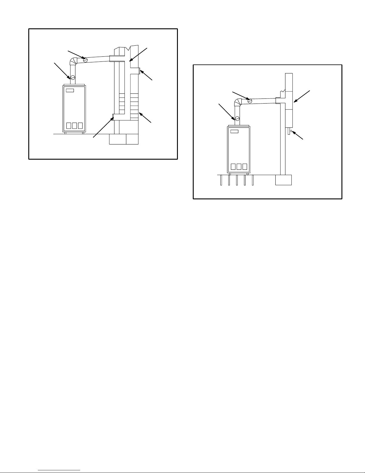
BAROMETRIC
CONTROL*
(IN EITHER
LOCATION)
MASONRY CHIMNEY
LINER
NOTE − If vent pipe needs to exit from side of cabinet,
use the pilot hole (located on either side of the unit) to
cut a 6" (152 mm) round hole. Attach finishing plate
(provided) with four sheet metal screws to cover rough
edges.
FACTORY−BUILT CHIMNEY
CLEAN OUT
MASONRY
CHIMNEY
CLEAN OUT
*Barometric control may be installed in either vertical or horizontal section of flue pipe within 18" of flue outlet of furnace.
Figure 6
10− Extend the vent pipe into the chimney so that it is flush
with the inside of the vent liner. Seal the joint between
the pipe and the liner.
11− The furnace shall be connected to a factory built chim-
ney or vent complying with a recognized standard, or
masonry or concrete chimney lined with a lining material acceptable to the authority having jurisdiction.
12− When two or more appliances vent into a common
vent, the area of the common vent should not be less
than the area of the largest vent or vent connection
plus 50% of the area of the additional vent or vent connection. Chimney must be able to sufficiently vent all
appliances operating at the same time.
13− The vent pipe shall not be connected to a chimney
vent serving a solid fuel appliance or any mechanical
draft system.
14− All unused chimney openings should be closed.
15− All vent pipe run through unconditioned areas or out-
side shall be constructed of factory built chimney sections. See figure 7.
16− Where condensation of vent gas is apparent, the vent
should be repaired or replaced. Accumulation of condensation in the vent is unacceptable.
17− Vent connectors serving this appliance shall not be
connected into any portion of mechanical draft systems operating under positive pressure.
18− Keep the area around the vent terminal free of snow,
ice and debris.
BAROMETRIC
CONTROL*
(IN EITHER
LOCATION)
*Barometric control may be installed in either vertical or horizontal section of flue pipe within 18" of flue outlet of furnace.
FACTORY
BUILT
CHIMNEY
DRAIN FOR
CONDENSATE
Figure 7
Combustion and Ventilation Air
(Confined and Unconfined Spaces)
In the past, there was no problem in bringing in sufficient
amounts of outdoor air for combustion − infiltration provided
all the air that was needed and then some. In today’s
homes built with energy conservation in mind, tight
construction practices make it necessary to bring in air
from outside for combustion. Consideration must also be
given to the use of exhaust fans, appliance vents, chimneys and fireplaces because they force additional air that
could be used for combustion out of the house. Unless outside air is brought into the home for combustion, negative
pressure (pressure outside is greater than inside pressure)
will build to the point that a down draft can occur in the furnace vent pipe or chimney. Combustion gases enter the living space creating a potentially dangerous situation.
The importance of the previous paragraph cannot be overstated. Users may inadvertently block fresh air intakes after
installation.
In the absence of local codes concerning air for combustion and ventilation, the following section outlines guidelines and recommends procedures for operating oil furnaces in a manner that ensures efficient and safe
operation. Special consideration must be given to combustion air needs as well as requirements for exhaust vents
and oil piping.
Page 7
 Loading...