

Page 1

APPLICATION
GUIDE
ErP
DIRECTIVE
2009/125/EC
ECODESIGN
&
LABELLING
NEOSYS
NAC - NAH
AIR COOLED CHILLER & HEAT PUMP
200 - 1000 kW
LENNOX participates in the ECP
Check ongoing validity of certifi cate :
programme for LCP-HP.
www.eurovent-certifi cation.com
www.lennoxemea.com
NEOSYS-AGU-1801-E
Page 2

Page 3
NEOSYS
APPLICATION GUIDE
GENERAL
1.
Model number description
Key customer benefi ts
Features and benefi ts
Technical description
Options and accessories
GENERAL DATA
2.
General data
Pressure drops
Hydraulic data
- eDrive
- Partial heat recovery
- Total heat recovery
- Free-cooling
Acoustic data
Operating limits
Ref : NEOSYS-AGU-1801-E
2
3
4
6
8
10
17
19
23
27
28
30
32
33
ELECTRICAL DATA
4.
Electrical tables
PERFORMANCES
5.
NAC 37
NAH 50
DIMENSIONAL DATA
6.
Dimensional data
Weight data
Product designed and manufactured
under quality management systems
certifi ed ISO 9001 and ISO 14001.
www.eurovent-certifi cation.com
www.certifl ash.com
Our company’s products comply
with European standards.
34
52
62
All the technical and technological information contained in this manual, including any drawing and technical descriptions
provided by us, remain the property of Lennox and must not be utilised (except in operation of this product), reproduced, issued to
or made available to third parties without the prior written agreement of Lennox.
Application Guide /NEOSYS-AGU-1801-E
• 1 •
Page 4

MODEL NUMBER DESCRIPTION
EXAMPLE :
N
A
C
200
D
N
M
5
M
NAC 200D N M5 M
NEOSYS
Air cooled
C = Cooling mode
H = Heat pump mode
Cooling capacity in kW
Number of circuits :
S = 1 circuit
D = 2 circuits
T = 3 circuits
F = 4 circuits
Non ducted
R410 A refrigerant
Revision number
400V/3/50 Hz
• 2 •
Application Guide / NEOSYS-AGU-1801-E
Page 5

KEY CUSTOMER BENEFITS
Air-cooled Liquid Chiller for outdoor installation (NAC)
Air-to-water Heat Pump for outdoor installation (NAH)
Nominal cooling capacity :
200 ► 1000 kW (NAC)
200 ► 450 kW (NAH)
Nominal heating capacity :
200 ► 500 kW (NAH)
Sustainable Performance
- Extended qualifi cation tests (vibration tests, run tests, fi eld
tests) to ensure superior reliability.
- High effi ciency aluminium micro channel heat exchanger
(MCHX) with improved corrosion resistance for moderate
marine or urban applications (Cooling only version). 3-year
warranty*.
- Specifi c MCHX coil design with high mechanical fi n resistance
that offers easy cleaning with high pressure air or water washers
for extended life cycle.
- V-coil design, compressor and hydraulic enclosure to protect
the unit against climatic conditions (e.g. sun rays, UV light, hail).
- Exclusive Compliant Scroll® compressor design with both
axial and radial compliance to increase compressor operation
tolerance of liquid refrigerant or debris, substantially improving
durability and reliability.
- Exclusive fan design with SKF hybrid Ceramic bearings
to double (treble in some cases) the service life of the motors
and to reduce noise level. With these sealed hybrid ceramic
bearings, our customer can expect little or no maintenance of
the motor throughout its life.
Quiet performance
3-year warranty*.
3-year warranty*.
Y
*
Y
E
T
N
3
A
R
A
R
Energy performance
-
High Energy Performance (ESEER above 4; EER up to 2.9 ;
COP up to 3,2) for improved energy consumption all around the
year.
- Aluminium micro channel heat exchanger that offers +10%
outstanding system effi ciency (cooling only version).
- R410A refrigerant for optimized system performance.
- Energy savings due to lower system minimum water content
reducing the time to reach setpoint. This can also eliminate the
need for a buffer tank.
Architectural integration
- State of the art design with hidden compressors, fans and
pump for perfect architectural integration.
- Flat top, aesthetic grilles, very low unit height (< 2 m) for
discrete installation on a roof reducing the requirement of costly
cladding solutions around the unit.
A
W
R
- Unique design with compressor, pump(s) and fan acoustic
enclosure to reduce radiated noise emissions.
- Inverter fans using external rotor technology associated with
high performance aluminium fan blades of the latest generation
(Owlet™ design).
- Elimination of intrusive fan start/stop noise that is irritating
to the human ear.
- Active Acoustic Attenuation System™ to meet changing
building load requirements while automatically adjusting the
air fl ow to meet night and day sound level constraints (Time
schedule with 4 time zones per day).
Quick performance and service
- Complete hydraulic module with single or twin, low or high
pressure pump (options) that includes all necessary equipment
for quick connection: pump(s), regulating valve, expansion tank
vessel with pressure gauge, pressure tapping points, water
fi lter, air vent, pressure relief valve and Victaulic connections.
- 400V, 50 Hz, 3 phase power supply (without neutral) with a
single point of power connection. Main on/off switch included
in as standard.
- Air spring powered Butterfl y electrical panel with jacks top
opening providing protection to service engineers against rain
or snow during commissioning and maintenance operations.
* This warranty covers parts only. The above warranty is liable if
the start-up and periodic maintenance agreement is contracted
by a LENNOX company or any company accredited by LENNOX.
Refer to LENNOX 3 year warranty conditions.
Application Guide /NEOSYS-AGU-1801-E
• 3 •
Page 6

FEATURES AND BENEFITS
Flat top and low profi le for best architectural
integration
The NEOSYS design is minded to be perfectly integrated into
urban or residential environments. The state of the art design of
NEOSYS includes a painted casing, a fl at top that hides the fans
and aesthetic protection grilles.
The very low unit height less than two meters makes easier for
architects and design engineers to integrate the unit on a roof.
Many interviewed customers confi rm that the state of the art
design of NEOSYS will replace any requirement of costly cladding
solutions around the unit.
ACTIVE ACOUSTIC ATTENUATION SYSTEM™
SELECT YOU MODE PER TIME ZONE
Performance Mode
Sound (dBA)
Compressor unloading
Max (dBA)
HP
Auto Quiet Mode
Sound (dBA)
Smarts acoustics with inverter fans
No more need to make a choice between a high effi ciency version,
a low noise or an ultra low noise version. NEOSYS can adapt all
situations with only one version. NEOSYS is fi tted in standard
with the Active Acoustic Attenuation System™ that is using an
electronic control associated with inverter fans. NEOSYS can
change automatically the speed of all the fans – from 0% to 100%
of the nominal air fl ow – to meet the building load requirements
while respecting maximum authorised noise level in the time zone.
NEOSYS is surely achieving the best acoustic signature of the
market thanks to the latest generation of Owlet™ high performance
aluminium fan blades and noiseless ceramic bearings.
Max (dBA)
Customer (dBA)
Sound (dBA)
Max (dBA)
Customer (dBA)
Compressor
unloading
Fan speed override
HP
Quiet Mode
Compressor
unloading
• 4 •
HP
Application Guide / NEOSYS-AGU-1801-E
Page 7

FEATURES AND BENEFITS
A high energy performance
4,60
4,40
4,20
4,00
ESEER
3,80
3,60
3,40
270 300 340 370 420 480 540 600
Screw R134A units
By using R410A refrigerant associated with high effi ciency micro
channel coils and variable speed fans NEOSYS is contributing to
a very low energy consumption all year around with an average
energy effi ciency ratio (ESEER)* in cooling mode above 4.0.
NEOSYS Heat-pumps are also achieving very high performances
in cooling and heating mode (COP* up to 3.2).
Furthermore NEOSYS advanced control allows energy savings
all year around by using smart control functions:
- Low water system quantity to reduce the time to reach the setpoint.
- Dynamic defrost (patented) to limit the number of defrost cycles.
- Set-point reset based on outside air temperature to relax the
chilled water set-point.
NEOSYS
kW
Scroll R410A units
Floating high pressure
LENNOX optimizes the performance of the NEOSYS chillers with
electronic expansion valve (as an option) and variable speed
ventilation (as standard) to achieve maximum energy savings.
We defi ne a condensation temperature depending on the outside
air temperature at an optimum value to obtain the lowest power
inputs of couples, compressors and condenser fan motors.
*ESEER : European Seasonal Energy Effi ciency Ratio in cooling mode.
COP : Coeffi cient of Performance in heating mode.
R410A Micro channel heat exchanger
With the use of fully
aluminium coils already
used in the automotive
industry, NEOSYS offers
many customer benefi ts:
- Up to 40% less refrigerant
charge that contributes to
reduce the total amount
of refrigerant used in the
system.
- A more effi cient system
(EER + 10%).
- An air heat exchanger
with signifi cantly impro-
ved corrosion resistance
results (x 2) from the
same aluminium alloy (no galvanic action) vs. the traditional
copper tube/aluminium fi n coils. By using this type of coil, units
can be used in light corrosive or seacoast environments without
any need for additional, and expensive, pre-treated fi ns or coil
coating.
- High mechanical resistance eases the cleaning with high pressure
air or water washers without any risk of damaging the fi ns.
Available in cooling only version, this technology will surely be
enlarged shortly to reversible applications.
Application Guide /NEOSYS-AGU-1801-E
• 5 •
Page 8

TECHNICAL DESCRIPTION
GENERAL CHARACTERISTICS OF THE UNIT
The NEOSYS unit is designed to be integrated into urban or
residential environments.
As main characteristics the NEOSYS unit offers state of the
art design to match architectural constraints and adjustable
sound level performances during day and night to satisfy local
environmental constraints.
CASING/CHASSIS
- Casing made of galvanised steel sheet metal painted with a white
powdered polyester paint and a red stripe.
- Fully grey colour painted chassis protecting against corrosion.
- State of the art design with hidden compressors, fans and pump
for perfect architectural integration.
- Flat top, aesthetic grilles, very low unit height (2 meters) for
discrete installation on a roof reducing the requirement of costly
cladding solutions around the unit
- Aesthetic side anti-intrusion grilles as standard to protect the
unit during transportation and against human aggressions.
COMPRESSOR
- Exclusive Compliant Scroll® design with both axial and radial
compliance to increase compressor operation tolerance to liquid
refrigerant, substantially improving durability and reliability. 3-year
warranty*.
- Motor cooled by suction gas.
- Electronic control of the compressor discharge temperature.
- Motor protection device against high temperature or over current
situations.
- Discharge non-return valve.
- Low noise scroll compressors mounted in a sound-proofed technical
cabinet to reduce noise emissions.
- Compressors assembly installed on an independent chassis
supported by anti-vibration mountings.
WATER HEAT EXCHANGER
- True dual circuit plate heat exchanger
- Copper brazed Stainless steel plate heat exchanger.
- 13 mm thermal insulation foam.
- Water heat exchanger located in a technical cabinet protecting
the insulation against climatic conditions (UV light, rain).
3-year warranty*
AIR HEAT EXCHANGER
- High effi ciency aluminium Micro Channel heat exchangers (MCHX)
with improved corrosion resistance in moderate marine or urban
environment (cooling only version). 3-year warranty*.
- Standard copper tubes/aluminium fi ns heat exchanger (heat pump
version).
- V-coil design to protect the unit against climatic conditions (e.g.
hail).
FANS
- Inverter fans (0 to 900 rpm operating range).
- Active Acoustic Attenuation System™ to meet changing building
load requirements while automatically adjusting the air fl ow to
respect night and day sound level constraints (adjustable setting
over time schedule with 4 time zones per day).
- Elimination of intrusive start/stop noise that is irritating to the
human ear.
- Fan-motor assembly using external rotor technology associated
with owlet high performance aluminium fan blades of the latest
generation.
- IP 54 electrical motor, class F protected against high temperature
with an internal sensor.
- Exclusive fan design with hybrid Ceramic bearings to extend the
service life of motors and to reduce noise level. With these sealed
hybrid ceramic bearings, our customer can expect little or no
maintenance of the motor throughout its life. 3-year warranty*.
- Extremely rigid fan assembly via the integration of the fans mounted
within a pre-formed bell mouth roof panel, thus improving rigidity
while reducing vibrations.
- Rounded top acoterion panels to hide the fans and reduce noise
emissions for quieter operation.
REFRIGERANT CIRCUIT
NEOSYS uses R410A refrigerant in 2 independent circuits
(minimum). Each circuit includes:
- A refrigerant charge reduced by 30% due to the use of R410A
combined with micro channel heat exchanger (NAC/Cooling only
version).
- Suction piping with thermal insulation.
- Filter drier with removable cartridge fi lter.
- Thermostatic or electronic expansion valve (Electronic device only
when "winter operation" option selected).
- Temperature sensors and pressure transducers.
- Four-way valve and liquid receiver (heat pump units only).
- Leak-tight refrigerant circuit with brazing carried out under nitrogen
by certifi ed engineers.
- Each refrigerant circuit is pressure and leak tested with a Hydrogen/
Nitrogen mixture, and vacuumed before being charged with
refrigerant. All units are then subjected to a complete functional
and operational run test to guarantee perfect sealing before
leaving the factory.
* Warranty under conditions - See page 3
• 6 •
Application Guide / NEOSYS-AGU-1801-E
Page 9

TECHNICAL DESCRIPTION
ELECTRICAL BOX
- Unit electrical cabinet, components and wiring in compliance with
EN 60204-1 electrical directive.
- 400V, 50 Hz, 3 phase power supply (without neutral) with a single
point of power connection (except sizes 680 to 1080).
- Bottom entry (through the base) for electrical power.
- IP54 protection class.
- Air spring powered Butterfl y electrical panel with top opening
providing protection to the service engineers against rain or snow
during commissioning and maintenance operations.
- Recognized brand electrical components (Schneider) for ease of
maintenance.
- Main on/off switch mounted on the front panel.
- DC60 advanced user interface mounted on the front panel.
- Main disconnect switch with high trip capacity allowing optimized
sizing of the customer power supply.
- 400/24 V transformer to supply the control circuit.
- Numbered electrical wires to facilitate maintenance and diagnostic.
- Variable Frequency Drives (VFD) to control the fan speed.
CONTROL
CLIMATIC microprocessor based control is providing the following
functions:
- 4 scheduling time zones per day over 7 days to allow energy
consumption and sound level management according to the
building use and environmental constraints.
- PI control of the water temperature with operating time equalisation
of the compressors.
- Water set-point offset based on outdoor air temperature.
- Active variable speed control of all fans to optimize the unit
condensing pressure and energy performances at full- and partload while meeting authorized maximum noise level in the time
zone (Active Acoustic Attenuation System™ control patented).
- Intelligent advanced control algorithm to protect the compressors
against excessive short-cycling and to allow operation of the unit
without buffer tank in most comfort air conditioning applications
(e.g. unit with fan-coils). Refer to minimum installation water loop
volume recommendations.
- Dynamic defrost to limit the number and the duration of the
defrost cycles in winter for high performance of the unit (Dynamic
Defrost patented).
- Automatic compressor unloading in case of excessive condensing
pressure allowing the operation of the machine at high outdoor
air temperature (operation extended up to 46°C ambient).
- Water pump control with operating time equalization and automatic
change-over in case of a pump fault (Twin pump only).
- Master/slave or cascade control of two chillers operating in parallel
with operating time equalization and automatic change-over in
case of a unit fault.
COMMUNICATION
The control board is equipped with a RS485 serial communication
port to allow remote management through communication bus.
According to the wished communication protocol, our control board
can be fi tted with ModBUS®, BacNET® (RS485 or TCP/IP) or
LonWorks® communication interface (options).
The main control board has free dry contacts that allow remote
control of the unit by wired cable:
- Remote on/off of the unit.
- Remote alarm reset to re-start the unit.
- Alarm or alert indications.
- Free customer contact.
With the optional extension board BE60, it is possible to get
additional customized digital or analog inputs / outputs for remote
control of the unit:
- Fault fans or pumps (dry contact).
- Operation indication at 100% on circuit 1 or 2 (dry contact).
- Dual water set-point management (dry contact).
- Force heating or cooling mode (24V AC input).
- Power limitation by disabling circuit 1 or 2 (24V AC input).
- Force unoccupied mode (24V AC input).
- Water set-point offset based on a 4-20mA signal. Note: non
available with heat-pump units.
DIRECTIVES
The unit is built to meet European norms and standards & Eurovent
certifi cation performance standards.
• DI 97/23/CE Pressure Equipment Directive.
• DI 98/37/CE Machinery Directive.
• DI 73/23/CE Low Voltage Directive.
• DI 89/336/CE Electro Magnetic Compatibility Directive
• EN 378-2 Safety and Environmental Directive.
• The European Restriction of the Use of Certain Hazardous
Substances (RoHS).
CLIMATIC is pre-factory confi gured with default settings allowing
a fast commissioning on site. The DC60 advanced user interface
with graphical display is easy to use, intuitive. Main customer
parameters can be read or modifi ed without main power shut-off
(Entering/leaving water temperatures, outdoor air temperature, alarm
history, scheduling of the different time zone, water and noise level
set-points, high and low pressure reading).
The DS60 service display (optional) is a “plug and play" controller
that allows service people to read and modify all unit parameters
(Unit settings, operating time and number of compressor starts,
low and high pressure reading, read the history of last 32 faults...).
Application Guide /NEOSYS-AGU-1801-E
• 7 •
Page 10

OPTIONS AND ACCESSORIES
OPTIONS DESCRIPTION ADVANTAGES MODELS
Low-pressure single-pump
hydraulic module
High-pressure single-pump
hydraulic module
Low-pressure twin-pump
hydraulic module
High-pressure twin-pump
hydraulic module
Partial heat recovery
Total heat recovery (Free
hot water : 100% heat
recovery)
Low-pressure single pump, regulating valve,
Victaulic couplings, fi lter and all necessary
hydraulic devices. Refer to specifi c chapter.
High-pressure single pump, regulating valve,
Victaulic couplings, fi lter and all necessary
hydraulic devices. Refer to specifi c chapter.
Low-pressure twin pumps, regulating valve,
Victaulic couplings, fi lter and all necessary
hydraulic devices. Refer to specifi c chapter.
High-pressure twin pumps, regulating valve,
Victaulic couplings, fi lter and all necessary
hydraulic devices. Refer to specifi c chapter.
Plate heat exchanger on each compressor
circuit allowing recovery of 20% of the rejected
heat
Recovery brazed plates heat exchanger dualcircuit mounted in parallel to the air condensers
allow 100% heat recovery in all outdoor air
conditions.
Quick start-up on job site. Available
pressure around 150 kPa.
Quick start-up on job site. Available
pressure around 250 kPa.
Quick start-up on job site. Available
pressure around 150 kPa.
Quick start-up on job site. Available
pressure around 250 kPa.
Allow free hot water production
simultaneously with unit operation
Production of free hot water at the
same time of the production of chilled
water.
NAC 200 ► 640
NAH 200 ► 480
NAC 200 ► 640
NAH 200 ► 480
NAC 200 ► 640
NAH 200 ► 480
NAC 200 ► 640
NAH 200 ► 480
NAC 200 ► 640
NAH 200 ► 300
NAC 200 ► 640
Free cooling
Winter operation (from +6°C
down to -20°C) – Cooling
only units
Brine operation (From +5°C
down to -10°C)
Anti-freeze protection (down
to -20°C)
Anti-freeze protection
of Total Heat Recovery
exchanger
Additional free cooling coils (one “V” or two “V”
depending on needed capacity) with inverter
fans and motorised valves.
Unit fi tted with electronic expansion valve and
variable frequency driven fans. Select “antifreeze protection” option if no glycol water
Unit fi tted with electronic expansion valve,
variable frequency driven fans and reinforced
evaporator and piping thermal insulation.
Resistance heaters on the evaporator,
hydraulic module and partial heat recovery if
selected. To be selected if no glycol water.
Resistance heater and insulation of the
recovery exchanger, to be selected if no glycol
water.
Allow the chilled water to run through
the free-cooling system, which uses
less power and utilises the lower
ambient air to cool the water.
Increased operating range in
cooling down to -20°C ambient
temperature. (Standard on sizes
540/600/640/1080).
Increased operating range in
cooling down to -10°C water leaving
temperature for thermal storage or
process cooling.
Evaporator and hydraulic module
frost protection down to -20°C
ambient temperature
The recovery exchanger have frost
protection down to -20°C ambient
temperature.
NAC 200 ► 540
NAC 200 ► 480
NAC 680 ► 960
NAC 200 ► 1080
NAC 200 ► 1080
NAH 200 ► 480
NAC 200 ► 640
Heavy anti-corrosion coil
treatment
Rear protection grille Metallic grille fi tted at the back of the unit
• 8 •
Application of LenGuard treatment on the
entire coil surface.
High corrosion resistance for
severe industrial, marine and dirty
environments.
Prevents the rear V-coil against
possible damage
Application Guide / NEOSYS-AGU-1801-E
NAC 200 ► 1080
NAH 200 ► 480
NAC 200 ► 640
NAH 200 ► 480
Page 11

OPTIONS AND ACCESSORIES
OPTIONS DESCRIPTION ADVANTAGES MODELS
Soft starter
Power Factor correction Capacitors fi tted into the unit
Electric meter
Single main power
connection
BE60 extension board for
additional inputs/outputs
Modbus communication
interface
Electronic soft starter fi tted into the electrical
cabinet
Active energy total counter, power factor,
operating time counter, max. active power
demand, ModBus.
Electrical cabinet equipped with one single
point of connection and power cut-off for the
complete unit.
Electronic extension board with additional
analog inputs (4), digital inputs (4) and digital
outputs (4). See control manual.
Communication card using ModBus/JBus
protocol with RS485 or TCP/IP connection.
Start-up current reduced by 15 % up
to 30 %.
Cos phi correction up to 0.95
to reduce current and energy
consumption.
This device allows monitoring of the
unit electric power consumption on
the unit and from a BMS
Allow easy electrical connection
with one single cable instead of two
cables
Relay card for remote control and
alarm report using dry contacts, 24
Vac or 4-20 mA signals.
Communication interface with a
building management system.
NAC 200 ► 1080*
NAH 200 ► 480
NAC 200 ► 1080
NAH 200 ► 480
NAC 200 ► 1080
NAH 200 ► 480
NAC 680 ► 1080
NAC 200 ► 1080
NAH 200 ► 480
NAC 200 ► 1080
NAH 200 ► 480
LonWorks® communication
interface
BACnet® communication
interface
Communication card using LonTalk® protocol
with FTT-10A connection.
Communication card using Bacnet® protocol
with RS485 or TCP/IP connection.
Communication interface with a
building management system.
Communication interface with a
building management system.
*except in case of main power connection option
NAC 200 ► 1080
NAH 200 ► 480
NAC 200 ► 1080
NAH 200 ► 480
ACCESSORIES DESCRIPTION ADVANTAGES MODELS
This protection must be fi tted in
Water fi lter
Flange connection
Anti-vibration mounts
DC60 remote comfort
display
1000 microns water Y fi lter delivered with
piping and fl ange connections.
Two connections sleeves with victaulic groove
and fl ange on opposite side.
Rubber anti-vibration mounts to be mounted
under the unit.
Customer display located at 600 meters
maximum from the unit.
the customer water supply piping
to protect the evaporator from any
possible impurities.
Allow easy connection with fl anges
on customer side.
Reduction of the transmission of
vibration to the ground and the
general level.
Remote customer parameter reading
and modifi cation.
NAC 200 ► 1080
NAH 200 ► 480
NAC 200 ► 1080
NAH 200 ► 480
NAC 200 ► 1080
NAH 200 ► 480
NAC 200 ► 1080
NAH 200 ► 480
Plug and play display delivered with 1 meter
DS60 service display
Adalink™ supervision
Application Guide /NEOSYS-AGU-1801-E
cable and connector for quick connection on
Climatic controller.
Electronic board with RS485 cables, RJ11
phone cable, Ethernet cable and power supply
cable.
Display for service technicians only.
Remote supervision of the unit via an
intuitive web page.
NAC 200 ► 1080
NAH 200 ► 480
NAC 200 ► 1080
NAH 200 ► 480
• 9 •
Page 12
GENERAL DATA
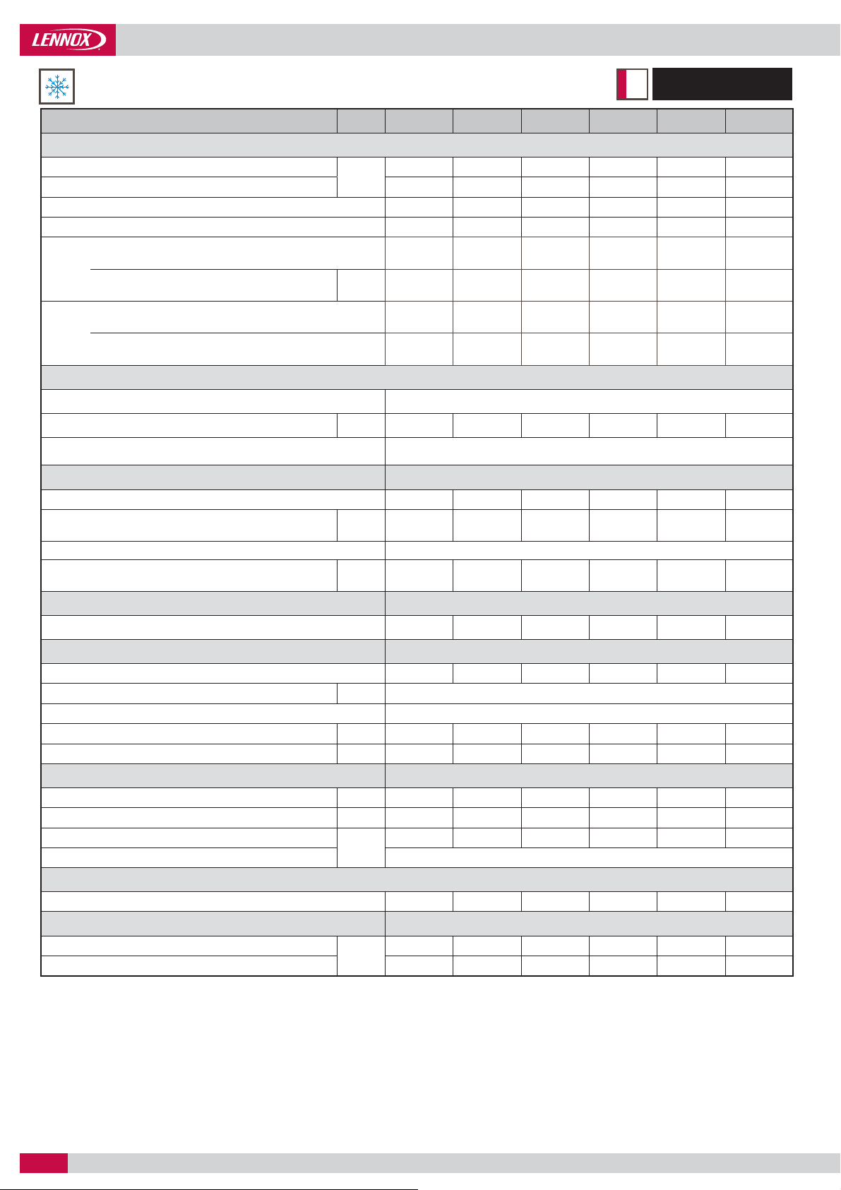
COOLING ONLY
410AR
NAC
NEOSYS NAC 200 230 270 300 340 380
Cooling mode
Cooling capacity
Total absorbed power
(1)
EER
(2)
ESEER
Comfort
applications
tions
Process
applica-
Refrigeration circuit
Number of circuit
Refrigerant load per circuit (R410A)
Type of expansion valve Thermostatic expansion valve
Compressors Scroll - Hermetic
Number of compressors
Capacity steps
Oil type MOBIL EAL Arctic 22CC or ICI EMKARATE RL32CF
Oil load per compressor l
(1)
(1)
Seasonal Energy Effi ciency Ratio
(3)
SEER
Seasonal energy efficiency
(4)
ɳs,c
Seasonal Energy Performance Ratio
SEPR - High temperature (7°C)
Seasonal Energy Performance Ratio
SEPR - Medium temperature (-8°C)
208,2 235,7 272,8 307,6 351,3 387,3
kW
72,1 85,7 106,7 106,9 125,6 149,1
2,89 2,75 2,56 2,88 2,80 2,60
4,24 4,03 3,99 4,04 4,15 3,90
3,83 3,85 3,82 3,89 3,89 3,99
% 150 151 150 153 153 157
(5)
(6)
4,88 4,93 5,01 4,95 4,98 5,01
3,20 3,26 3,50 3,30 3,40 3,50
2
kg 12,4/13 12,3/13 14,1/15 18,2/19,1 22,4/19,3 22,4/19,4
444455
%
+ (3,2+6,8)
31-62-81-
100
(3,2+6,8)
34-68-84-
100
(3,2+6,3)
+ (3,2+6,3)
28-57-78-
100
(6,8+6,3)
+ (6,8+6,3)
27-53-73-
100
(6,3x2)
+ (6,8+6,3)
18-41-59-
82-100
(6,8x3)
+ (6,3x2)
20-40-60-
80-100
(6,3x3)
+ (6,3x2)
Condenser Microchannel Aluminium Tube and fi ns
Number of condenser
444666
Fan & Motor Variable speed fans
Number of fans
Diameter
mm 800
444666
Maximum speed Variable speed - 900 rpm maximum
3
m
Nominal air fl ow (100%)
Total motor power input (900 rpm)
/h 87 200 87 200 87 200 130 800 130 800 130 800
kW 6,4 6,4 6,4 9,6 9,6 9,6
Evaporator AISI 304 stainless steel plate brazed with copper heat exchanger
Water fl ow rate
(1)
Water volume l
Pressure drop
(1)
Water operating pressure
m3/h 35,8 40,6 46,9 52,9 60,4 66,6
13 13 16 24 35 35
kPa
43,0 54,1 55,9 48,1 34,7 41,6
600
Hydraulic connections Victaulic
Water inlet/outlet
Electrical data
Start-up intensity
Maximum current
(1) EUROVENT certifi ed data, in accordance
with standard EN14511 :
Water inlet/outlet temperature = 12°C / 7°C
Outdoor air temperature = 35°C.
(2) ESEER following Eurovent calculation
method, in accordance with standard
EN14511
(3) SEER in accordance with standard
EN14825.
(4) Following ecodesign regulation nr
EU 2016/2281 on space cooling,
normalized leaving water temperature
at 7°C, in accordance with standard
EN14825.
(5) Following ecodesign regulation nr
EU 2016/2281 on process cooling units,
normalized leaving water temperature
at 7°C, in accordance with standard
EN14825.
4" 4" 4" 4" 5" 5"
400V / III / 50 Hz
393,9 446,5 475,7 498,0 527,9 572,0
A
166,5 195,8 225,0 247,3 277,2 321,3
(6) Following ecodesign regulation nr
EU 2015/1095 on process cooling chillers,
normalized leaving water temperature
at -8°C, in accordance with standard
EN14825.
• 10 •
Application Guide / NEOSYS-AGU-1801-E
Page 13
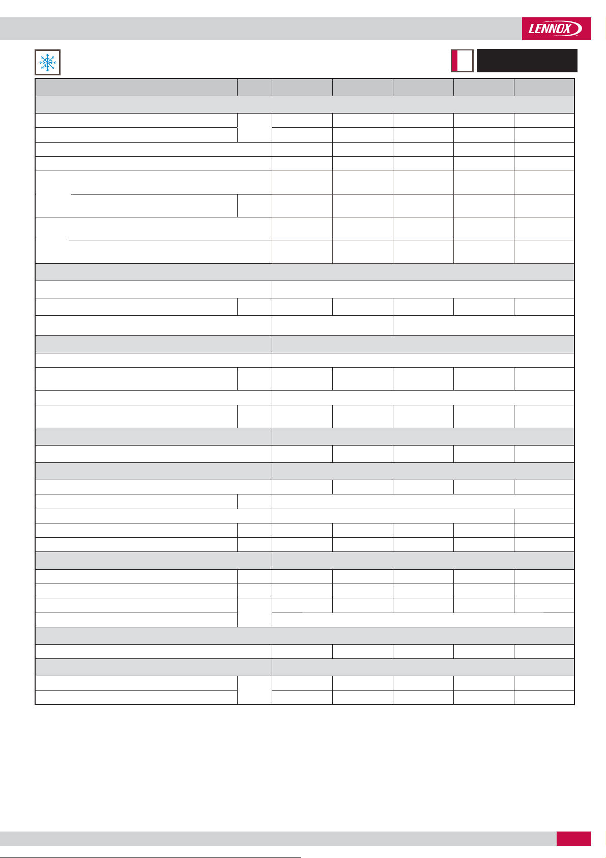
GENERAL DATA
COOLING ONLY
410AR
NAC
NEOSYS NAC 420 480 540 600 640
Cooling mode
Cooling capacity
Total absorbed power
(2)
EER
(3)
ESEER
Comfort
applications
tions
Process
applica-
Refrigeration circuit
Number of circuit
Refrigerant load per circuit (R410A)
Type of expansion valve Thermostatic expansion valve Electronic expansion valve
Compressors Scroll - Hermetic
Number of compressors
Capacity steps
Oil type MOBIL EAL Arctic 22CC or ICI EMKARATE RL32CF
Oil load per compressor
(1)
(1)
Seasonal Energy Effi ciency Ratio
(3)
SEER
Seasonal energy efficiency
(4)
ɳs,c
Seasonal Energy Performance Ratio
SEPR - High temperature (7°C)
Seasonal Energy Performance Ratio
SEPR - Medium temperature (-8°C)
kW
429,6 489,9 530,9 605,0 626,9
152,3 174,3 201,9 219,1 226,1
2,82 2,81 2,63 2,76 2,77
4,19 4,01 4,0 4,15 4,17
4,12 4,11 4,17 4,15 4,17
% 162 161 164 163 164
(5)
(6)
5,02 5,04 5,02 5,01 5,01
3,50 3,60 3,60 3,70 3,70
2
kg 34 34 34 42,5 42,5
6
14-33-48-67-81-
%
(6,3x3)
+ (6,8x3)
100
17-33-50-67-
83-100
(6,3x3)
+ (6,3x3)
18-33-51-67-
85-100
(6,3x3)
+ (6,3x3)
17-33-50-67-
83-100
(6,3x3)
+ (6,3x3)
17-33-50-67-
83-100
(6,3x3)
+ (6,3x3)
Condenser Microchannel aluminium tube and fi ns - Air cooled
Number of condenser
8 8 8 10 10
Fan & Motor Variable speed fans
Number of fans
Diameter
mm 800
8 8 8 10 10
Maximum speed Variable speed - 900 rpm maximum
Nominal air fl ow (100%)
Total motor power input (900 rpm)
3
m
/h 174 400 174 400 174 400 218 000 218 000
kW 12,8 12,8 12,8 16 16
Evaporator AISI 304 stainless steel plate brazed with copper heat exchanger
Water fl ow rate
(1)
Water volume
Pressure drop
(1)
Water operating pressure
3
m
/h 73,9 84,3 91,3 104,1 107,9
35 43 43 52 56
kPa
50,3 48,8 56,7 59,0 58,4
600
Hydraulic connections Victaulic
Water inlet/outlet
Electrical data
Start-up intensity
Maximum current
(1) EUROVENT certifi ed data, in accordance
with standard EN14511 :
Water inlet/outlet temperature = 12°C / 7°C
Outdoor air temperature = 35°C.
(2) ESEER following Eurovent calculation
method, in accordance with standard
EN14511
(3) SEER in accordance with standard
EN14825.
A
(4) Following ecodesign regulation nr
EU 2016/2281 on space cooling,
normalized leaving water temperature
at 7°C, in accordance with standard
EN14825.
(5) Following ecodesign regulation nr
EU 2016/2281 on process cooling units,
normalized leaving water temperature
at 7°C, in accordance with standard
EN14825.
5" 5" 6" 6" 6"
400V / III / 50 Hz
594,8 638,9 765,9 817,0 817,0
344,1 388,2 431,7 482,8 482,8
(6) Following ecodesign regulation nr
EU 2015/1095 on process cooling chillers,
normalized leaving water temperature
at -8°C, in accordance with standard
EN14825.
Application Guide /NEOSYS-AGU-1801-E
• 11 •
Page 14

GENERAL DATA
COOLING ONLY
410AR
NAC
NEOSYS NAC 680 760 840 960 1080
Cooling mode
Cooling capacity
Power input
(2)
EER
(3)
ESEER
Comfort
applications
tions
Process
applica-
Refrigeration circuit
Number of circuit
Refrigerant load per circuit (R410A)
Type of expansion valve Thermostatic expansion valve
Compressors
Number of compressors
Type of compressor Scroll - Hermetic
Capacity steps
Oil type MOBIL EAL Arctic 22CC or ICI EMKARATE RL32CF
Oil load per compressor l
Condenser Microchannel aluminium tube and fi ns
Number of condenser
Fan & Motor Variable speed fans
Number of fans
Diameter
Maximum speed Variable speed - 900 rpm maximum
Nominal air fl ow (100%)
Total motor power input (900 rpm)
Evaporator AISI 304 stainless steel plate brazed with copper heat exchanger
Water fl ow rate
Water volume l
Pressure drop
Water operating pressure
Hydraulic connections Victaulic
Water inlet/outlet
Electrical data
Start-up intensity
Maximum current
(1)
(1)
Seasonal Energy Effi ciency Ratio
(3)
SEER
Seasonal energy efficiency
(4)
ɳs,c
Seasonal Energy Performance Ratio
SEPR - High temperature (7°C)
Seasonal Energy Performance Ratio
SEPR - Medium temperature (-8°C)
(1)
(1)
kW
702,6 774,7 859,1 979,8 1061,9
251,3 298,2 304,6 348,7 403,8
2,80 2,60 2,82 2,81 2,63
4,15 3,91 4,21 4,01 4,0
4,14 4,14 4,22 4,11 4,11
% 163 163 166 162 162
(5)
(6)
5,05 5,03 5,01 5,04 5,01
3,60 3,50 3,50 3,60 3,60
4
kg
22,4/19,3/
22,4/19,3
22,4/19,4/
22,4/19,4
34 34 34
Electronic expan-
sion valve
10 10 12 12 12
9-18-30-41-
%
50-59-70-82-
[(6,8x3) +
(6,3x2)] x 2
91-100
10-20-30-4050-60-70-80-
90-100
[(6,3x3) +
(6,3x2)] x 2
8-15-24-33-
41-48-58-67-
74-82-91-100
[(6,3x3) +
(6,8x3)] x 2
8-17-25-33-
42-50-58-67-
75-83-92-100
[(6,3x3) + (6,3x3)] x 2
8-15-24-33-41-48-
58-67-74-82-91-
100
12 12 16 16 16
12 12 16 16 16
mm 800
3
m
/h 261 600 261 600 348 800 348 800 348 800
kW 19,2 19,2 25,6 25,6 25,6
3
m
/h 120,9 133,3 147,8 168,6 182,7
275 290 300 335 345
kPa
57,0 51,3 56,0 66,0 71,0
600 600 600 600 600
8"
400V / III / 50 Hz
805,2 893,3 939,0 1027,1 1197,6
A
554,5 642,6 688,3 776,4 863,4
(1) EUROVENT certifi ed data, in accordance
with standard EN14511 :
Water inlet/outlet temperature = 12°C / 7°C
Outdoor air temperature = 35°C.
(2) ESEER following Eurovent calculation
method, in accordance with standard
EN14511
(3) SEER in accordance with standard
EN14825.
• 12 •
(4) Following ecodesign regulation nr
EU 2016/2281 on space cooling,
normalized leaving water temperature
at 7°C, in accordance with standard
EN14825.
(5) Following ecodesign regulation nr
EU 2016/2281 on process cooling units,
normalized leaving water temperature
at 7°C, in accordance with standard
EN14825.
(6) Following ecodesign regulation nr
EU 2015/1095 on process cooling chillers,
normalized leaving water temperature
at -8°C, in accordance with standard
EN14825.
Application Guide / NEOSYS-AGU-1801-E
Page 15

GENERAL DATA
COOLING ONLY
410AR
NAC
Acoustic data
NEOSYS NAC 200 230 270 300 340 380
Active Acoustic Attenuation System™
Global sound power level
Sound pressure level 10 meters from the unit
Minimum global sound power level with A
Minimum sound pressure level with A3 system
10 meters from the unit
NEOSYS NAC 420 480 540 600 640
Global sound power level
Sound pressure level 10 meters from the unit
Minimum global sound power level with A
Minimum sound pressure level with A3 system
10 meters from the unit
NEOSYS NAC 680 760 840 960 1080
Global sound power level
Sound pressure level 10 meters from the unit
Minimum global sound power level with A
Minimum sound pressure level with A3 system
meters from the unit
(1) All data are at Eurovent condition,
(1)
89,2 89,3 89,7 91,2 91,3 91,4
57 57 58 59 59 59
3
system
(3)
(3)
dB(A)
82,2 82,8 84,4 85,0 85,5 85,9
51 52 54 54 55 55
Active Acoustic Attenuation System™
(1)
92,5 92,6 93,0 94,0 94,0
61 61 61 62 62
3
system
(3)
(3)
dB(A)
86,5 86,8 88,2 89,3 89,3
56 56 57 59 59
Active Acoustic Attenuation System™
(1)
94,3 94,4 95,5 95,6 96,0
62 62 64 64 64
3
system
(3)
(3)
- 10
dB(A)
88,5 88,9 89,5 89,8 91,2
58 58 59 59 60
Gross cooling capacity with 12/7°C water temperature and 35°C air ambient.
Gross heating capacity with 7°C air inlet temperature and 40/45°C water temperature.
EER and COP according to EN14511 Eurovent calculation method
Dimensional data
NEOSYS NAC 200 230 270 300 340 380 420 480 540 600 640
Dimensions
Length
mmWidth
Height
Footprint m²
Operating weight
kg
Shipping weight
NEOSYS NAC 680 760 840 960 1080
Dimensions
Length
mmWidth
Height
Footprint m²
Operating weight
kg
Shipping weight
3590 4620 5650 6680
2280 2280 2280 2280
2025 2025 2025 2025
8,2 10,5 12,9 15,2
1983 2011 2278 2676 3003 3045 3580 3661 3712 4152 4175
1961 1989 2253 2643 2955 2997 3532 3604 3655 4086 4105
9040 11100
2280 2280
1964 1964
20,6 25,3
6770 6854 7981 8141 8229
6495 6564 7681 7806 7884
Application Guide /NEOSYS-AGU-1801-E
• 13 •
Page 16

GENERAL DATA
HEAT PUMP
410AR
NAH
NEOSYS NAH 200 230 270 300
Cooling mode
Cooling capacity
Total absorbed power
Full load amps
(1)
EER
(2)
ESEER
tions
applica-
Comfort
tions
Process
applica-
Heating mode
Heating capacity
Power input
Full load amps
(3)
COP
Comfort
applications
Compressors Scroll - Hermetic
Number of compressors
Capacity steps
Oil type MOBIL EAL Arctic 22CC or ICI EMKARATE RL32CF
Oil load per compressor
Refrigeration circuit
Number of circuit
Refrigerant load per circuit (R410A)
Type of expansion valve Thermostatic expansion valve
Condenser Copper tube - Aluminium fi n - Air-cooled
Number of condenser
Fan & Motor Variable speed fans
Number of fans
Diameter
Maximum speed Variable speed - 900 rpm maximum
Nominal air fl ow (100%)
Total motor power input
Evaporator AISI 304 stainless steel plate brazed with copper heat exchanger
Water fl ow
Water volume
Pressure drop
Water operating pressure
Hydraulic connections Victaulic
Water inlet/outlet
Electrical data
Starting current
Maximum current
(1) EUROVENT certifi ed data, in accordance with
standard EN14511 :
Water inlet / outlet temperature = 12 °C / 7 °C
Outdoor air temperature = 35 °C.
(2) ESEER following Eurovent calculation method,
in accordance with standard EN14511
(3) Following ecodesign regulation nr
EU 2016/2281 on space cooling, normalized
leaving water temperature at 7 °C, in
accordance with standard EN14825.
(1)
(1)
(1)
Seasonal Energy Effi ciency Ratio
SEER
Seasonal energy effi ciency
(3)
ɳs,c
Seasonal Energy Performance Ratio
SEPR - High temperature (7°C)
Seasonal Energy Performance Ratio
SEPR - Medium temperature (-8°C)
(1)
(1)
(1)
Seasonal energy effi ciency
(8)
SCOP
Seasonal energy effi ciency
(7)
ɳs,h
Seasonal energy effi ciency class
(1)
(1)
(9)
kW
A 127,9 150,7 185,6 203,5
(4)
% 154 154 154 157
(5)
(6)
kW
A 125,9 145,3 172,8 192,5
% 134 130 132 135
%
kg 28 28 40 42
mm 800
3
/h 76 000 76 000 114 000 114 000
m
kW 6,4 6,4 9,6 9,6
3
m
/h 32,9 37,3 46,6 50,8
kPa
A
(4) SEER in accordance with standard
EN14825.
(5) Following ecodesign regulation nr
EU 2016/2281 on process cooling units,
normalized leaving water temperature at 7°C,
in accordance with standard EN14825.
(6) Following ecodesign regulation nr
EU 2015/1095 on process cooling chillers,
normalized leaving water temperature at
-8°C, in accordance with standard EN14825
191 217 271 295
73,5 86,7 106,7 117,0
2,60 2,50 2,54 2,52
4,00 3,76 3,99 3,94
3,93 3,91 3,92 4,00
5,20 5,04 5,06 5,01
3,15 3,20 3,02 3,09
219 235 291 339
71,7 84,0 104,3 112,7
3,05 2,80 2,78 3,01
3,44 3,32 3,39 3,45
A+
4
31 - 62 81 - 100
(3,2+6,8)
+ (3,2+6,8)
34 - 68 84 - 100
(3,2+6,3)
+ (3,2+6,3)
28 - 57 78 - 100
(6,8+6,3)
+ (6,8+6,3)
25 - 50 75 - 100
(6,3x2)
+ (6,3x2)
2
4466
4466
20 20 23,2 23,2
36,7 46,4 55,2 44,7
600
4"
400V / III / 50 Hz
393,9 446,5 483,3 512,7
166,5 195,8 232,6 262,0
(7) SCOP in accordance with standard
EN14825. Heating mode performance is
defi ned for average climate.
(8) Following ecodesign regulation nr
EU 813/2013 on space heaters, normalized
leaving water temperature at 7°C, in
accordance with standard EN14825, average
climate.
(9) Following energy labelling regulation nr
EU 811/2013 on space heaters.
• 14 •
Application Guide / NEOSYS-AGU-1801-E
Page 17

GENERAL DATA
HEAT PUMP
410AR
NAH
NEOSYS NAH 340 380 420 480
Cooling mode
Cooling capacity
Total absorbed power
Full load amps
(1)
EER
(2)
ESEER
tions
applica-
Comfort
tions
Process
applica-
Heating mode
Heating capacity
Power input
Full load amps
(3)
COP
Comfort
applications
Compressors Scroll - Hermetic
Number of compressors
Capacity steps
Oil type MOBIL EAL Arctic 22CC or ICI EMKARATE RL32CF
Oil load per compressor l
Refrigeration circuit
Number of circuit
Refrigerant load per circuit (R410A)
Type of expansion valve Thermostatic expansion valve
Condenser Copper tube - Aluminium fi n - Air-cooled
Number of condenser
Fan & Motor Variable speed fans
Number of fans
Diameter
Maximum speed Variable speed - 900 rpm maximum
Nominal air fl ow (100%)
Total motor power input
Evaporator AISI 304 stainless steel plate brazed with copper heat exchanger
Water fl ow
Water volume l
Pressure drop
Water operating pressure
Hydraulic connections Victaulic
Water inlet/outlet Inches
Electrical data
Starting current
Maximum current
(1) EUROVENT certifi ed data, in accordance with
standard EN14511 :
Water inlet / outlet temperature = 12 °C / 7 °C
Outdoor air temperature = 35 °C.
(2) ESEER following Eurovent calculation method,
in accordance with standard EN14511
(3) Following ecodesign regulation nr
EU 2016/2281 on space cooling, normalized
leaving water temperature at 7 °C, in
accordance with standard EN14825.
(1)
(1)
(1)
Seasonal Energy Effi ciency Ratio
SEER
Seasonal energy effi ciency
(3)
ɳs,h
Seasonal Energy Performance Ratio
SEPR - High temperature (7°C)
Seasonal Energy Performance Ratio
SEPR - Medium temperature (-8°C)
(1)
(1)
(1)
Seasonal energy effi ciency
(8)
SCOP
Seasonal energy effi ciency
(7)
ɳs,h
Seasonal energy effi ciency class
(1)
(1)
kW
A 223,3 231,4 269,7 311,9
(4)
% 166 165 162 163
(5)
(6)
kW
A 125,9 145,3 172,8 192,5
% 136 132 130 131
(9)
%
kg 42 50 52 52
mm 800
3
/h 114 000 152 000 152 000 152 000
m
kW 9,6 12,8 12,8 12,8
3
/h 55,7 62,1 68,4 78,1
m
kPa
A
(4) SEER in accordance with standard
EN14825.
(5) Following ecodesign regulation nr
EU 2016/2281 on process cooling units,
normalized leaving water temperature at 7°C,
in accordance with standard EN14825.
(6) Following ecodesign regulation nr
EU 2015/1095 on process cooling chillers,
normalized leaving water temperature at
-8°C, in accordance with standard EN14825
324 361 397 454
128,4 133,1 155,1 179,4
2,52 2,71 2,56 2,53
4,01 4,08 3,86 4,14
4,23 4,20 4,12 4,16
5,21 5,25 5,11 5,12
3,23 3,09 3,11 3,19
363 404 452 499
121,3 132,9 151,7 169,5
3,00 3,04 2,98 2,95
3,47 3,39 3,33 3.35
A+
5666
18 - 41 - 59 -
82 - 100
(6,8 x 3)
+ (6,3 x 2)
17 - 33 - 50 - 67
- 83 - 100
(6,8 x 3)
+ (6,8 x 3)
14 - 33 - 48 - 67
- 81 - 100
(6,3 x 3)
+ (6,8 x 3)
17 - 33 - 50 - 67
- 83 - 100
(6,3 x 3)
+ (6,3 x 3)
2
6888
6888
34,6 34,6 34,6 42,7
29,8 36,5 43,6 42,3
600
5"
400V / III / 50 Hz
527,9 579,6 594,8 638,9
277,2 328,9 344,1 388,2
(7) SCOP in accordance with standard
EN14825. Heating mode performance is
defi ned for average climate.
(8) Following ecodesign regulation nr
EU 813/2013 on space heaters, normalized
leaving water temperature at 7°C, in
accordance with standard EN14825, average
climate.
(9) Following energy labelling regulation nr
EU 811/2013 on space heaters.
Application Guide /NEOSYS-AGU-1801-E
• 15 •
Page 18

GENERAL DATA
HEAT PUMP
410AR
NAH
Acoustic data
NEOSYS NAH 200 230 270 300 340 380 420 480
Active Acoustic Attenuation System™
Global sound power level
Sound pressure level
10 meters from the unit
Minimum global sound power level with A
Minimum sound pressure level with A3 system
10 meters from the unit
(1) All data are at Eurovent condition,
(1)
dB(A)
3
system
(3)
(3)
89,2 89,3 91,1 91,2 91,3 92,4 91,5 91,6
57 57 59 59 59 61 61 61
82,2 82,8 84,9 85,0 85,5 86,1 86,2 86,5
51 52 54 54 55 56 56 56
Gross cooling capacity with 12/7°C water temperature and 35°C air ambient.
Gross heating capacity with 7°C air inlet temperature and 40/45°C water temperature.
EER and COP according to EN14511 Eurovent calculation method
Dimensional data
NEOSYS NAH 200 230 270 300 340 380 420 480
Dimensions
Length
mmWidth
Height
Footprint m²
Operating weight
kg
Shipping weight
3590 4620 5650
2280 2280 2280
2025 2025 2025
8,2 10,5 12,9
2176 2175 2906 3380 3349 4020 4066 4148
2154 2153 2881 3347 3301 3972 4020 4091
• 16 •
Application Guide / NEOSYS-AGU-1801-E
Page 19

PRESSURE DROPS
EVAPORATOR AND CONDENSER CURVES
Curves
100
NAC/NAH
NAC
200
230
270
300
340
380
420
480
540
600
640
680
760
840
960
1080
Evaporator
ABB
ACC
BCC
CCD
DCD
DCE
DCE
EGG
EJJ
FJJ
GJ J
H-
H-
H-
I-
I-
AB C
Evaporator pressure drop in units with
total heat recovery option
200
Condenser
D
Pressure Drop (kPa)
10
20 30 50 80
Flow rate (m3/h)
b
NEOSYS
200/230
270
300
340/380/420
480/540
600
640
540/600/640
ΔP = a X
ab
0,057 1,8516
0,0419 1,8695
0,0333 1,8333
0,0175 1,8509
0,0124 1,8669
0,009 1,892
0,0082 1,8953
0,0072 1,9104
100
E
F
100
H
I
G
J
Pressure Drop (kPa)
10
50 70 100 200
Flow rate (m3/h)
b
NEOSYS
680
760
840
960
1080
ΔP = a X
ab
0,0056 1,8666
0,0056 1,8666
0,0056 1,8666
0,0042 1,886
0,0042 1,886
Pressure drops are given for information only. A tolerance of +/- 20 kPa must be considered when selecting water pumps.
Application Guide /NEOSYS-AGU-1801-E
• 17 •
Page 20

PRESSURE DROPS
FILTER CURVE
NAC/NAH NAC
200
230 600
270 640
300 680
340
380 840
420 960
480 1080
Curve Curve
540
L
760
M
10
1
L
N
O
MN
O
0,1
Pressure drop (kPa)
0,01
1 4 10 50 100 200
Flow rate (m3/h)
Size of the fi lter mesh: 1 mm
NEOSYS
200/230/270/300
340/380/420/480
540/600/640
680/760/840/960/1080
ab
0,00332 1,7409
0,0000011 3,1026
8,00E-09 4,023
0,0000000005 4,2717
ΔP = a X
b
• 18 •
Pressure drops are given for information only. A tolerance of +/- 20 kPa must be considered when selecting water pumps.
Application Guide / NEOSYS-AGU-1801-E
Page 21

0
HYDRAULIC DATA
NAC
NAH ---
Nominal water fl ow m3/h
200 230 270 300 340 380 420 480
35,8 40,5 46,9 52,9 60,4 66,6 73,9 84,3 91,3 104,0 107,8
540 600 640
Single pump
Available static pressure
(1)
kPa
101 119 89 127 125 144 125 107 146 133 130
Double pump
Available static pressure
(1)
kPa
80 92 82 119 116 136 115 95 133 115 110
Single pump HP
Available static pressure
(1)
kPa
191 218 201 207 215 202 214 192 230 215 212
Double pump HP
Available static pressure
(1)
kPa
171 204 203 206 213 198 202 171 213 191 186
Expansion vessel
Volume l
Maximum pressure kPa
Gross Weight kg
50
400
12,2
(1) : Pump external static pressure - Evaporator pressure drop
PUMP PRESSURE CURVES
Low pressure
Single pump
240,0
220,0
200,0
180,0
160,0
140,0
120,0
100,0
80,0
60,0
40,0
Pressure drop (kPa)
20,0
0,0
0 20 40 60 80 100 120 140
B
A
E
D
C
Flow rate (m3/h)
360,0
330,0
300,0
F
270,0
240,0
210,0
180,0
150,0
120,0
90,0
Pressure drop (kPa)
60,0
30,0
0,0
0102030405060708090100110
High pressure
Single pump
A
Flow rate (m3/h)
C
E
B
D
F
Low pressure
Double pump
240,0
220,0
200,0
180,0
160,0
140,0
120,0
100,0
80,0
60,0
40,0
Pressure drop (kPa)
20,0
0,0
0 20 40 60 80 100 120 14
B
A
E
D
C
Flow rate (m3/h)
A NAC/NAH 200 D NAC/NAH 300/340
B NAC/NAH 230 E NAC/NAH 380/420/480
C NAC/NAH 270 F NAC 540/600/640
Application Guide /NEOSYS-AGU-1801-E
High pressure
Double pump
330,0
300,0
270,0
240,0
F
210,0
180,0
150,0
120,0
90,0
60,0
Pressure drop (kPa)
30,0
0,0
0 102030405060708090100110
C
B
A
E
D
F
Flow rate (m3/h)
A NAC/NAH 200 D NAC/NAH 300/340/380
B NAC/NAH 230 E NAC/NAH 420/480
C NAC/NAH 270 F NAC 540/600/640
• 19 •
Page 22

HYDRAULIC DATA
UNIT WITH HYDRAULIC MODULE
NAC/NAH
200 - 230 - 270 - 300
05
04
02
01
IN
01 07
02 08
03 09
04 10
05 11
06 12
03
03
09
12
OUT
10
Water fi lter (item supplied loose) Electronic fl ow switch
Air purge Plate heat exchanger
Pressure tap Setting valve
Pump Pressure tap and drain valve
Safety valve with manometer Return temperature sensor
Expansion vessel Supply temperature sensor
07
11
08
06
NAC 340 - 380 - 420 - 480 - 540 - 600 - 640
NAH 340 - 380 - 420 - 480
06
05
1111
0202
1212
0303
0707
0404
0303
0101
08
09
10
MINIMUM WATER CONTENT OF AN INSTALLATION
Thanks to multi step capacity control and smart anti-short compressor cycling, NEOSYS can work with minimum water loop volume
as defi ned here below. This can eliminate the need for a buffer tank in most of air-conditioning applications (e.g. NEOSYS application
with fan-coil units).
Vmini = 86 x Q / (Nstages x Dt)
V
Q
Where :
Nstage Number of control steps available in the unit
Dt
Important note: In case NEOSYS is used in air-conditioning applications with a short water system (e.g. NEOSYS application with air
handling units) or in case NEOSYS is used for industrial process cooling, it is mandatory to use a buffer tank.
Minimum water content of the installation
Cooling capacityof the chiller
Maximum acceptable temperature rise (Dt = 6°c for an air conditioning application)
• 20 •
Application Guide / NEOSYS-AGU-1801-E
Page 23

HYDRAULIC DATA
MINIMUM WATER CONTENT OF AN INSTALLATION
Unit Size
NAC
200
230
270
300
340
380
420
480
540
600
640
680
760
840
960
1080
Number of stages
4 717
4 824
4 968
4 1075
5 975
5 1089
6 1003
6 1147
6 1290
6 1433
6 1529
10 975
10 1089
12 1003
12 1147
12 1290
Mini water volume
(l)
Unit Size
NAH
200
230
270
300
340
380
420
480
Number of stages
4 717
4 824
4 968
4 1075
5 975
6 908
6 1003
6 1147
Mini water volume
(l)
MAXIMUM WATER CONTENT OF AN INSTALLATION
The maximum water content of the installation is determined by the capacity of the expansion vessel.
On units fi tted with a standard Hydraulic Module it is possible to determine the maximum water content of the installation.
Max. volume clear water (l) Max. volume Glycol water (l)
Unit Size
200-230-270
300-340-380
420-480
540
600-640
Expansion
vessel
volume
50 l 1,5 Bar 5 230 l 4 180 l 4 020 l 3 210 l
Pressure in
the expansion
vessel
Static pressure Static pressure
5 m 10 m 5 m 10 m
GLYCOL CORRECTION FACTOR
Minimum ambient temperature or water
outlet temperature
+ 5°C ► 0°C 10% 1,05 1,02 0,99 0,994
Ethylene
glycol
Pressure
drop
Water
fl ow
CAPACITIES
Cooling Heating
0°C ► -5°C 20% 1,10 1,05 0,98 0,993
- 5°C ► -10°C 30% 1,15 1,08 0,97 0,99
- 10°C ► -15°C 35% 1,18 1,10 0,96 0,987
Example : 10% glycol
Minimum fl ow : 1,19 m3/h x 1,02
Pressure drop x 1,07
System capacity x 0,99
Application Guide /NEOSYS-AGU-1801-E
• 21 •
Page 24

HYDRAULIC DATA
MINIMUM WATER FLOW THROUGH THE EVAPORATOR
In case of installation with fi xed speed pump, to prevent from freezing risk, the fl ow rate through the evaporator must be higher than
the minimum fl ow given in the table below.
In case of variable primary fl ow, the pump speed must be controlled through the CLIMATIC control. Additionally, the hydraulic system
must be properly designed and balanced to ensure a right water fl ow distribution through the chiller evaporator and the terminal units.
This is especially important when the system is designed with fan coils equipped with two-way valves. When the two-way valves are
closing in response to building load change, it is important that the system is designed to ensure a minimum evaporator fl ow that is
always minimum 60% of the chiller’s design fl ow rate. This can be done with a bypass from chilled water supply to chilled water return
opened via a signal from a fl ow meter.
Additionnaly, some terminals can be fi tted with three way control valves in order to ensure the fl ow will not drop below the minimum
value at any load condition as indicated in the table below.
Water fl ow rate (m³/h)
Models Capacity (kW)
200
230
270
300
340
380
420
480
540
600
640
680
760
840
960
1080
208 21,5 35,8 57,9
236 24,4 40,6 57,9
273 28,1 46,9 57,9
308 31,7 52,9 126,4
351 36,2 60,4 126,4
387 40,0 66,6 126,4
430 44,3 73,9 126,4
490 50,6 84,3 126,4
531 54,8 91,3 126,4
605 62,5 104,1 126,4
627 64,7 107,9 126,4
702 72,6 121,0 252,9
774 80,1 133,4 252,9
860 88,8 148,0 252,9
980 101,3 168,8 252,9
1062 109,7 182,9 252,9
Minimum
(with fi xed and eDrive™
variable speed pump)
Nominal Maximum
Important note : The water fl ow must not vary by more than 10% per minute. If the fl ow rate changes more rapidly, the system should
contain a minimum of 6,5 litres of water per kW instead of 3 l/kW.
• 22 •
Application Guide / NEOSYS-AGU-1801-E
Page 25

HYDRAULIC EQUIPMENT
eDrive™ TECHNOLOGY, THE RIGHT CHOICE TO SAVE 75% OF PUMP ENERGY COSTS.
LENNOX offers the eDrive, a variable speed drive pump option (with single or double pump) which modulates the water fl ow through
the evaporator and reduces energy costs. This option is available on chillers and heat pumps from 20 to 1000 kW.
In a water system, one major contributor to annual energy consumption is the pump motor. Pumping energy cost can represent 20%
of the total cost of owning a chiller. This ratio can be even bigger for a heat-pump.
eDrive™ variable speed driven pump is contributing to continuous Lennox efforts to save energy while exploring possibilities
to reduce installation cost.
eDrive™ variable speed driven pump benefi ts:
• Cost savings on the energy consumption especially at part-load conditions and during off period.
75% of this energy could be saved !
• Cost savings on the initial system cost. Fewer pumps and piping connections than primary–secondary systems, terminal units
equipped with two-way control valves instead of three-way valves, elimination of water fl ow set valve.
• Flexibility and accuracy in the pump operation control (smooth start and stop, gradual change of speed, accuracy and stability of
control)
• Reduction of the repeated stress on the pump and piping resulting in longer equipment life time (elimination of the «hammer blow»
in pipes).
• Elimination of the start-up current thanks to variable frenquency drive that controls a gradual pump motor supply.
Designing a VWF chilled water plant that performs reliably at all load conditions requires careful attention to chiller design. Thanks
to the newest generation of chiller controllers and intensive testing, NEOSYS can now reliably maintain the desired chilled water
temperature with a fl ow range from 60% to 100% that gives up to 75% annual energy savings.
LENNOX eDrive™ Technology modulates the Water Flow especially in Part-Load Conditions through a Specifi c Algorithm and a
Variable Frequency Driver.
Typical cost split in a chiller through 15-year lifespan
Chiller with fixed speed pump Chiller with variable speed pump
20 %
10 %
22 %
Energy savings
15 %
47 %
10 %
23 %
5 %
47 %
Cooling energy cost Maintenance cost
Equipment cost Pump energy cost
Application Guide /NEOSYS-AGU-1801-E
• 23 •
Page 26

0
10
20
30
40
50
60
70
80
90
100
0
10
20
30
40
50
60
70
80
90
100
HYDRAULIC EQUIPMENT
eDrive™ VARIABLE WATER FLOW SAVES YOUR MONEY IN THE ENERGY COST
• Through the elimination of the energy normally lost in the water fl ow control valve during unit full-load operation (Variable water
fl ow = perfect pump curve adjustment to the required nominal water fl ow and delta P)
• Through pump rotation speed reduction during unit part-load operation.
• Thanks to pump running at minimum speed during Chiller “off” period (night, unoccupied)
Pump energy consumption
Fan coil with 3 way valves and constant T
PUMP AFFINITY LAWS
“The power required for pumps varies as the
Energy
20% water fl ow reduction = 50% energy reduction.
40% water fl ow reduction = 80% energy reduction.
cube of the fl ow rate.”
100% load 75% load 50% load 25% load Off
Chiller load
Fixed speed pump Variable speed pump
eDrive™ VARIABLE WATER FLOW MAY SAVE MONEY IN THE SYSTEM DESIGN COST
Variable speed
drive
Terminal unit
1
Terminal unit
2
Terminal unit
...
Control
valve
Water pressure
transducer
Pump
Balancing
valve
PP
By-pass valve
Variable primary fl ow system with constant pressure
A variable primary fl ow design uses fewer components than primary–secondary systems as the pumps of the secondary distribution
loop and the mixing tank are eliminated.
When compared with constant primary fl ow systems, terminal units can equipped with two-way control valves instead of three-way valves
often used in constant volume systems. Using two-way valves instead of three-way valve on fan coils represent a budget reduction
that pays for the variable frequency driver cost. On top of that, the water fl ow set valve is eliminated as the pump adjustment to real
installation needs can be done electronically. These factors may reduce the initial cost of the chilled water system
• 24 •
Application Guide / NEOSYS-AGU-1801-E
Page 27

HYDRAULIC EQUIPMENT
eDrive™ VARIABLE WATER FLOW BY LENNOX
3 control modes available :
Constant speed
• Interest to set the right installation design fl ow (avoid setting valve).
Constant Delta P (setting to declare the required working pressure)
• Implementation and management adapted to systems with two-way valves and bypass of the installation to ensure a minimum
water fl ow back into the evaporator.
Constant Delta T (Setting to declare the required delta T)
• Need a good installation with well balanced circuits to ensure good fl ow distribution when the fl ow is reduced.
• Installation with terminal units fi tted with 3-way valves.
Operation for each mode:
• Constant speed : eDrive pilots the pump to the water fl ow desired when the compressors are in operation. When the compressors
are stopped (dead zone), control will automatically reduce the speed of the pump to the minimum water fl ow This minimum fl ow
is also adjustable within minimum 30Hz (60% fl ow).
• Constant delta P : the eDrive™ regulation is managing the pump to maintain the required delta P in order to keep constant the
customer available static pressure. When the terminals control valves close in response to decreased building loads, the pump
controller slows the pump speed to maintain the target delta P. In this mode the pump does not detect terminal capacity reduction
(fan speed staging)
• Constant Delta T : the eDrive™ regulation is managing the pump to maintain the required Delta T. When the Delta T is increasing
in response to the number of compressors running, the pump controller increases the speed of the pump. Conversely, when the
compressors are stopping in response to decreased building loads, the pump controller slows the pump speed to maintain the
target Delta T.
Safety parameters:
• If the evaporating pressure reaches the low limit (risk of evaporator frosting), the fl ow is increased.
• If the outlet evaporator temperature reaches the low limit, the fl ow is set to the maximum.
• When the pump speed varies and the fl ow switch trips, the fl ow is automatically increased.
• During defrost procedure (HP), the fl ow is set to the maximum.
• Pump motor supply range from 30 Hz minimum to 50Hz maximum. Minimum pump motor frequency set at 30 Hz. Below this value,
risk of pump motor failure due to overheat.
• For safe operation of the chiller, the unit is protected by the fl ow switch.
• Minimum and maximum admissible water fl ow per unit size: with constant delta T, the fl ow may vary from 60% to 100% of the
selected pump nominal fl ow.
• Maximum change in fl ow rate through the evaporator: a 10% per minute change in fl ow rate is admissible in most of air conditioning
applications.
Application Guide /NEOSYS-AGU-1801-E
• 25 •
Page 28

HYDRAULIC EQUIPMENT
Installation instructions to respect in case of variable primary fl ow:
• The hydraulic system will have to be properly designed and balanced to ensure a right water fl ow distribution through the chiller
evaporator and the terminal units.
• The hydraulic system will have to be properly designed to respect minimum and maximum water fl ow through each chiller following
the values given by the manufacturer.
Case of constant Delta P mode :
• In case of system designed with terminal units equipped with 2 way valves, the hydraulic system will need to have a bypass fl ow
to ensure a minimum water fl ow through the chiller evaporator.
Méthode de by-pass :
• Bypass adequate water fl ow can be achieved with a slow modulating opening as soon as the water fl ow rate is near the mini-
mum. When the water fl ow rises according to predefi ned setting, this valve closes. This bypass modulating valve provided by
LENNOX (contact customer service) is controlled by our Climatic control. The bypass should be positioned at the beginning of
the installation near the unit and allows signifi cant energy savings and cost as opposed to a location at the end of the system.
• An alternative is to install some 3-way valves at different points of the terminal units. This approach allows constant minimum
fl ow in the chiller or heat pump and ensures a cheaper system.
• The minimum water fl ow through the chiller evaporator will need to respect a minimum value that is 60% of the nominal chiller
water fl ow.
• The fl ow bypass from chilled water supply to chilled water return can be done with a motorized bypass valve opened via a signal
from a fl ow meter.
• For safe operation some terminals can be equipped with three way control valves in order to ensure the fl ow will not drop below
the minimum value at any load condition.
• The water fl ow must not vary by more than 10% per minute. If the fl ow rate changes more rapidly, the system should contain a
minimum of 6,5 liters of water per kW instead of 3 liters/kW.
• Check the control valve authority in low load periods, especially in case of long pipe hydraulic systems.
• 26 •
Application Guide / NEOSYS-AGU-1801-E
Page 29

PARTIAL HEAT RECOVERY
Compared with the basic confi guration, this option features an additional refrigerant/water
heat exchanger on the compressor discharge line, allowing recovery of 15% of the rejected
heat. This heat exchanger is large enough to recover heat for the production of free hot
water simultaneously with chilled water production. The heating capacity of the heat recovery
circuit is approximately equal to the power input of the compressor.
Typical heat recovery applications can be facilities with high domestic hot water usage,
such as health care, hotels, etc.
Notes:
This option is available on cooling only and heat-pump versions.
Heat recovery can only occur when the unit is running either in cooling or heating mode.
Partial heat recovery
Free hot water up to 70°C
Air cooled condenser
Desuperheater
Electronic expansion valve
Partial heat recovery
Scroll compressor
Evaporator
Water in/out: 50/55 °C Water in/out: 55/60 °C Water in/out: 50/60 °C
Recovery
(kW)
NAC/NAH 200
NAC/NAH 230
NAC/NAH 270
NAC/NAH 300
NAC 340
NAC 380
NAC 420
NAC 480
NAC 540
NAC 600
NAC 640
Wf : Dp :
Water fl ow in m3 per hour Water pressure drop in KPa
41 7,18 6,00 32 5,62 4 37 3,26 2
52 9,11 9,00 43 7,55 6 48 4,22 2
56 9,81 7,00 44 7,73 5 50 4,40 2
65 11,39 9,17 52 9,13 6 59 5,19 2
79 13,84 9,80 64 11,24 6 72 6,34 2
101 17,69 14,28 83 14,58 10 93 8,18 3
91 15,94 9,17 73 12,82 6 82 7,22 2
106 18,57 12,00 86 15,11 8 96 8,45 3
143 25,05 15,00 118 20,73 11 129 11,35 4
150 26,28 13,00 122 21,43 9 136 11,97 3
154 27,07 13,33 125 22,07 9 139 12,33 3
Wf
3
(m
/h)Dp(kPa)
Recovery
(kW)
Wf
(m3/h)Dp(kPa)
Recovery
(kW)
Wf
(m3/h)Dp(kPa)
Application Guide /NEOSYS-AGU-1801-E
• 27 •
Page 30

TOTAL HEAT RECOVERY
Heat recovery is one of our solutions to decrease and offset energy
bills continually on the rise.
NEOSYS with Heat Recovery option operate as a standard chiller
as long as heat is not required or simultaneously produce chilled
and hot water which can be used for applications like preheating
of a boiler, heating or domestic hot water.
Heating or preheating in series with a boiler, the heat recovery
option enables to reduce :
- Purchase and installation cost : boiler is undersized.
- Operating cost : free hot water when unit produce chilled
water.
In series with an auxiliary heater , this option can also replace the
heater in low temperature heating systems.
A heat recovery chiller is suitable for all industrial process requiring
both chilled and hot water.
The LENNOX total heat recovery system on NEOSYS :
- Parallel assembly, stainless steel brazed plate heat exchanger
mounted in parallel to the air condensers maintain maximum
performance and effi ciency whatever the conditions : 100%
heat recovery in opposite of series assembly.
- Free hot water from 25 to 55°C
- Very Low refrigerant charge, no additional refrigerant charge
thanks to braze plate heat exchanger.
- High Total Energy Ratio values : TER (*)
- Standard Features factory mounted and tested:
• Stainless steel heat exchanger with control
• Paddle water fl ow switch
• Temperature hydraulic sensors
• Victaulic coupling
• 3 way valve ( 0-10V) for cold start
• On/Off pump control
• Antifreeze protection + insulation (in option)
(*) TER: Total Effi ciency Ratio is the total energy effi ciency of the units
when there is a production of chilled water and hot water simultaneously.
Cold water and hot water are valuated to the total power consumption
of the unit: TER = (cooling capacity + recovered heating capacity) / total
power consumption.
Control principle:
The unit switches to recovery mode using a dry contact supplied
by the user and connected to the CLIMATIC. CLIMATIC controller
regulates the water leaving temperature of the recovery exchanger
using temperature probes included at inlet and outlet of the
exchanger. It offers the possibility of programming schedule one
or more setpoints.
Recovery capacity is entirely dependent of the cooling needs.
The capacity step is important due to two independent refrigerant
circuits and varies depending on the number of compressor ;
Unit with 4 compressors
Cooling capacity step Heat recovery step
27% 27%
53% 27% or 53%
73% 53% or 73%
100% 53% or 100%
Unit with 6 compressors
Cooling capacity step Heat recovery step
17% 17%
33% 17% or 33%
50% 33% or 50%
67% 33% or 67%
83% 67% or 83%
100% 50% or 100%
CLIMATIC provides a dry contact to control the on/off of the
pump(s). It also delivers a 0 -10V signal to control a 3-way valve
to avoid cold start if the inlet water temperature is too low ensuring
the correct operation of the unit. The use of a 3-way valve can
be avoided by using a variable speed pump. This solution allows
for greater control of the output temperature of water and thus to
reduce the power consumption of the pump.
Protection against lack of water fl ow is provided by a paddle fl ow
switch included in the option.
Total heat recovery : 100%
Free hot water up to 55°C
• 28 •
Air cooled condenser
Recovery condenser
Scroll compressor
Electronic expansion valve
Application Guide / NEOSYS-AGU-1801-E
Evaporator
Page 31

TOTAL HEAT RECOVERY
Operating limits
Maxi. outlet water temperature
Mini. outlet water temperature
Min. difference water inlet/outlet
Max. difference water inlet/outlet
Mini. water temperature at start-up
°C
20
46
60
55
5
3
8
Outlet water temperature (°C)
-15 -10 -15
Evaporator water outlet temperature (°C)
50
45
40
35
30
25
20
15
-5 0 5 10 15 20
Cooling capacity in recovery mode kW
Absorbed power in recovery mode kW
Recovered heating capacity kW
EER in heat recovery mode
COP in heat recovery mode
Total effi ciency ratio = (CC+HC)/PI
WATER IN/OUT = 35/40°C
Water fl ow m
Exchanger pressure drop kPa
Cooling capacity in recovery mode kW
Absorbed power in recovery mode kW
Recovered heating capacity kW
EER in heat recovery mode
NAC
200 230 270 300 340 380 420 480 540 600 640
214,1 253,9 300,2 318,9 374,5 431,8 455,1 521,4 586,8 657,7 664
64,1 73,9 92,3 94,2 109,9 125,4 135,6 149,6 172,2 197,2 197,8
264,3 311,4 372,9 392,4 460,2 529,3 561,1 637,5 721,1 812,1 818,7
3,34 3,44 3,25 3,39 3,41 3,44 3,36 3,49 3,41 3,34 3,36
4,12 4,21 4,04 4,17 4,19 4,22 4,14 4,26 4,19 4,12 4,14
7,46 7,65 7,29 7,55 7,60 7,66 7,49 7,75 7,60 7,45 7,50
3
/h
45,6 53,7 64,3 67,7 79,4 91,3 96,8 110 124,4 140,1 141,2
53 49 69 43 58 57 63 61 72 89 91
201,3 239,3 282,2 301,6 352 406,5 428,4 491 553,4 619,5 624,6
70,3 81,3 101,2 103,6 120,7 137,9 148,9 164,5 188,5 214,5 214,9
258,1 304,5 364,2 385 449 517,2 548,5 622,7 704,7 792,4 797,6
2,86 2,94 2,79 2,91 2,92 2,95 2,88 2,98 2,94 2,89 2,91
COP in heat recovery mode
Total effi ciency ratio = (CC+HC)/PI
WATER IN/OUT = 40/45°C
Water fl ow m
Exchanger pressure drop kPa
Cooling capacity in recovery mode kW
Absorbed power in recovery mode kW
Recovered heating capacity kW
EER in heat recovery mode
COP in heat recovery mode
Total effi ciency ratio = (CC+HC)/PI
WATER IN/OUT = 45/55°C
Water fl ow m
Exchanger pressure drop kPa
Exchanger volume dm
3,67 3,75 3,60 3,72 3,72 3,75 3,68 3,79 3,74 3,69 3,71
6,53 6,69 6,39 6,63 6,64 6,70 6,56 6,77 6,67 6,58 6,62
3
/h
44,5 52,5 62,8 66,4 77,4 89,2 94,6 107,4 121,6 136,7 137,6
51 47 66 41 55 54 61 58 69 85 86
178,9 210,1 253,1 266,9 313,1 359,5 381,2 430,7 488,5 552,6 556,6
80 94,4 113,3 120,9 137,6 158,9 169,3 191,1 214,6 238,2 238,5
245,9 289,3 348,1 368,4 428,2 492,5 523 590,7 667,9 751,4 755,3
2,24 2,23 2,23 2,21 2,28 2,26 2,25 2,25 2,28 2,32 2,33
3,07 3,06 3,07 3,05 3,11 3,10 3,09 3,09 3,11 3,15 3,17
5,31 5,29 5,31 5,25 5,39 5,36 5,34 5,34 5,39 5,47 5,50
3
/h
21,2 23,9 23,9 31,8 34,7 42,5 45,1 50,9 57,6 64,8 65,1
13 12 17 11 14 14 15 14 18 22 22
3
15,8 23,9 23,9 34,7 34,7 42,8 42,8 56,2 60,3 60,3 60,3
Exchanger connection diameters
Application Guide /NEOSYS-AGU-1801-E
4"/4" 4"/4" 4"/4" 5"/5" 5"/5" 6"/6" 6"/6" 6"/6" 6"/6" 6"/6" 6"/6"
• 29 •
Page 32

FREE COOLING
Compared with the basic confi guration this option features one or two additional V free cooling coils at the back of the unit. The free
cooling includes two motorised valves, allowing the chilled water to run through the free-cooling coils, which uses less power and
utilises the lower ambient air to cool the water. The cooling capacity of one V free cooling coil at 0°C ambient is approximately 100 kW.
NEOSYS free cooling system is using the same fans and speed inverters as for the standard unit in order to keep the same acoustic
capabilities. The hydraulic module options are compatible with the Free Cooling option but glycol is of course required.
Typical free cooling applications can be facilities with cooling demand all along the year, such as offi ces with high internal loads like
computer rooms, data centers, etc. In the North and North-East part of Europe, the ambient temperature is below 5°C between 20
and 45% of the year that makes this option very attractive.
Control principle
The control principle is the following: if ambient Temperature < return Temperature – 3°C, motorised valves open to by-pass return
water fl ow through the Free Cooling coils. The Free Cooling fans are driven by the CLIMATIC 60 via a specifi c PID algorithm. The Free
cooling operation is considered as a cooling stage that has a priority on the compressor stages: only if the free cooling fan speed has
reached the maximum fan speed then the compressors are allowed to run with their own PID.
Advantages of the NEOSYS free cooling system
• Simultaneous compressor cooling capability to reach building needs in any conditions (vs. DX free cooling that can not operate
simultaneous compressor and free cooling).
• Design with additional V free cooling coils to eliminate unnecessary air pressure drop when running 100% in compressor cooling
mode thus reducing all along the year energy fan consumption (vs. traditional free cooling system with free cooling coils located in
series with the condensing coil.)
• Free cooling as soon as the air outside is cold enough (3°C below return water temperature).
• Reduce the running use of the compressors.
• Extend the life expectancy of the compressors.
• EER up to 63 (Water 15/10°C, Air -15°C).
• Reduce power costs.
• Payback could be as little as 12 months
Compressor
Evaporator
Air condensers
Free cooling coils
Water in
15°C
Water pump (option)
10°C
Water out
• 30 •
Application Guide / NEOSYS-AGU-1801-E
Page 33

FREE COOLING
Example of free cooling:
Unit running 100% in free cooling mode:
Return water temperature: 12°C (30% glycol)
Number of "V" 1V for NAC 200 to 540 2V for NAC 200 to 540
Air fl ow m
Water fl ow m3/h
Ambient temperature °C
Outlet temperature °C
Free cooling capacity kW
Free cooling absorbed power kW
EER
Free cooling pressure drop to be added to
evaporator pressure drop
kPa
Return water temperature: 15°C (30% glycol)
3
/h
38000 76000
36 72
-15 -10 -5 0 5 -15 -10 -5 0 5
6,7 7,7 8,7 9,7 10,7 6,7 7,7 8,7 9,7 10,7
190 153 117 82 47 380 306 234 164 94
3,2 3,2 3,2 3,2 3,2 6,4 6,4 6,4 6,4 6,4
59 48 37 26 15 59 48 37 26 15
57 62
Number of "V" 1V for NAC 200 to 540 2V for NAC 200 to 540
3
Air fl ow m
Water fl ow m
Ambient temperature °C
Outlet temperature °C
Free cooling capacity kW
Free cooling absorbed power kW
EER
Free cooling pressure drop to be added to
evaporator pressure drop
/h
3
/h
38000 76000
36 72
-15 -10 -5 0 5 -15 -10 -5 0 5
9 10,1 11,1 12,1 13,1 9 10,1 11,1 12,1 13,1
214 177 140 104 69 428 354 280 208 138
3,2 3,2 3,2 3,2 3,2 6,4 6,4 6,4 6,4 6,4
67 55 44 33 22 67 55 44 33 22
kPa
57 62
Application Guide /NEOSYS-AGU-1801-E
• 31 •
Page 34

ACOUSTIC DATA
IMPORTANT NOTE : Thanks to variable speed fans, maximum sound level can be reduced.
NEOSYS maximum air fl ow can be adjusted between 70 % and 100 % of the nominal airfl ow to meet
maximum sound level requirements.
Please contact LENNOX for noise level calculations at reduced airfl ow.
Maximum global sound
power
EUROVENT
Hz
Lw dB(A)
89
89
89
91
91
91
92
92
93
94
94
94
94
95
95
96
NAC
200
230
270
300
340
380
420
480
540
600
640
680
760
840
960
1080
Spectrum per octave band dB(A)
125
Hz
68 79 83 85 82 75 68
68 80 84 85 82 76 68
68 80 84 85 83 76 68
70 82 85 87 84 78 70
70 82 85 87 84 78 70
70 82 86 87 84 78 70
71 83 87 88 85 79 71
71 83 87 88 86 79 71
71 83 87 89 87 80 71
72 83 88 90 88 81 72
72 83 88 90 88 81 72
73 85 88 90 87 81 73
73 85 89 90 88 81 73
74 86 90 91 88 82 74
74 86 90 91 89 82 74
74 86 90 92 90 83 74
250
Hz
500Hz1000Hz2000Hz4000Hz8000
NAC
Maximum sound
pressure at 10 meters
envelopping surface
(1)
Lp dB(A)
58
58
58
60
60
60
61
61
62
63
63
63
63
64
64
65
Spectrum per octave band dB(A)
NAH
200
230
270
300
340
380
420
480
(1) : For information only: Data calculated by enveloping envelopping surface method in free open fi eld.
125
Hz
68 79 83 85 82 75 68
68 80 84 85 82 76 68
70 82 85 87 84 78 70
70 82 85 87 84 78 70
70 82 85 87 84 78 70
71 83 87 88 85 79 71
71 83 87 88 85 79 71
71 83 87 88 86 79 71
250
Hz
500Hz1000Hz2000Hz4000Hz8000
Maximum global sound
power
EUROVENT
Hz
Lw dB(A)
Enveloping Surface
89
89
91
91
91
92
92
92
NAH
Maximum sound
pressure at 10 meters
envelopping surface
(1)
Lp dB(A)
58
58
60
60
60
61
61
61
• 32 •
h+d
L+ 2d
d
d
l+ 2d
A = 2(L+2d)(h+d)+2(l+2d)(h+d)+(L+2d)(l+2d)
Application Guide / NEOSYS-AGU-1801-E
Page 35

-25
-20
-15
-10
-5
0
5
10
15
20
25
30
35
40
45
50
-12 -7 -2 3 8 13 18
OPERATING LIMITS
NAC
NAC
Min. outlet water temperature
Min. outlet water temperature with brine operation option
Max. inlet water temperature
Min. difference water inlet/outlet
Max. difference water inlet/outlet
Min. outside air temperature
Min. outside air temperature
Winter operation option
Maximum outside air temperature :
Full capacity operation
NAH
Cooling mode
Min. outlet water temperature
Max. inlet water temperature
Min. difference water inlet/outlet
Max. difference water inlet/outlet
Min. outside air temperature
Maximum outside air temperature :
Full capacity operation
Heating mode
Min. condenser outlet water temperature
Max. condenser outlet water temperature
Min. difference water inlet/outlet
Max. difference water inlet/outlet
Min. outside air temperature (Water outlet
temp. : 37°C)
Max. outside air temperature
NAH 200 > 480
°C 5
°C 20
°C 3
°C 8
°C 6
°C 46
NAH 200 > 480
°C 24
°C 50
°C 3
°C 8
°C - 12
°C 30
200 >
340
380
420 -
480
540
600 >
680
760
840 -
960
1080
°C 5
°C - 10
°C 20
°C 3
°C 8
°C 6
°C - 20
°C 46 43 46 43 46 43 46 43
NAC
Operating enveloppe
Cooling mode
(°C)
50
45
40
35
30
25
20
15
10
5
0
-5
-10
Outdoor air temperature (°C)
-15
-20
-25
-12 -7 -2 3 8 13 18
Maximum outdoor air temperature = 43°C on NAC 380 / NAC 540
and NAC 1080
Glycol
Glycol
+
Brine operation option
Evaporator water outlet (°C) with Delta T = 3°C
Winter cooling
operation option
(°C)
NAH
Operating enveloppe
Cooling mode
Outdoor air temperature (°C)
Application Guide /NEOSYS-AGU-1801-E
Please consult us
Evaporator water outlet (°C) with Delta T = 3°C
Operating enveloppe
50°C
45°C
40°C
35°C
30°C
25°C
20°C
Condenser water outlet (°C)
15°C
NAH
Heating mode
10°C 15°C5°C0°C 20°C-5°C-10°C 25°C 30°C
Outdoor air temperature (°C)
• 33 •
Page 36

ELECTRICAL DATA
UNITS
NAC
NEOSYS 200 230 270 300 340 380 420 480 540 600 640
Minimum and maximum voltage
Maximum power
Maximum current
Maximum current
(with cos phi 0,95 option)
Start-up intensity
Start-up intensity
(with cos phi 0,95 option)
Start-up intensity
(with softstarter option)
Start-up intensity
(with softstarter and cos phi 0,95 options)
Maximum connectable power section
V
kW
96,7 113,7 135,0 147,1 166,2 191,7 205,9 231,4 258,1 288,4 288,4
A
166,5 195,8 225,0 247,3 277,2 321,3 344,1 388,2 431,7 482,8 482,8
A
152,6 162,7 191,9 211,2 237,3 272,3 294,4 329,4 366,0 410,2 410,2
A
393,9 446,5 475,7 498,0 527,9 572,0 594,8 638,9 765,9 817,0 817,0
A
382,6 423,2 452,4 471,7 497,8 523,8 554,9 589,9 712,3 756,5 756,5
A
255,7 314,4 343,6 365,9 395,8 439,9 462,7 506,8 579,3 630,4 630,4
A
236,4 261,7 290,9 310,2 336,3 371,3 393,4 428,4 489,4 533,6 533,6
mm²
185 185 185 300 300 300 300 300 300 300 300
380 V / 420 V
UNITS (dual connection point - as Standard)
NEOSYS 680 760 840 960 1080
Minimum and maximum voltage
Maximum power per box
Maximum current per box
Maximum current per box
(with cos phi 0,95 option)
Start-up intensity per box
V
kW
166,2 191,7 205,9 231,4 258,1
A
277,2 321,3 344,1 388,2 431,7
A
237,3 272,3 294,4 329,4 366,0
A
527,9 572,0 594,8 638,9 765,9
380 V / 420 V
Start-up intensity per box
(with cos phi 0,95 option)
Start-up intensity per box
(with sofstarter option)
Start-up intensity per box
(with softstarter and cos phi 0,95 options)
Maximum connectable power section
mm²
A
497,8 523,8 554,9 589,9 712,3
A
395,8 439,9 462,7 506,8 579,3
A
336,3 371,3 393,4 428,4 489,4
2 x 300
UNITS (single main power connection as an option)
NEOSYS 680 760 840 960 1080
Minimum and maximum voltage
Maximum power
Maximum current
Maximum current
(with cos phi 0,95 option)
Start-up intensity
Start-up intensity
(with cos phi 0,95 option)
Start-up intensity
(with softstarter option)
Start-up intensity
(with softstarter and cos phi 0,95 options)
V
kW
332,4 383,4 411,8 462,8 516,2
A
554,5 642,6 688,3 776,4 863,4
A
474,7 544,6 588,9 658,8 732,0
A
805,2 893,3 939,0 1027,1 1197,6
A
735,2 796,1 849,4 919,3 1078,3
A
673,1 761,2 806,9 895,0 1011,0
A
573,7 643,6 687,9 757,8 855,4
380 V / 420 V
Maximum connectable power section
• 34 •
mm²
Application Guide / NEOSYS-AGU-1801-E
Page 37

ELECTRICAL DATA
OPTIONS
NEOSYS
Single pump
Double pump
Low
Single pump - Double pump
pressure
Maximum current
Single pump
Double pump
High
Single pump - Double pump
pressure
Maximum current
Evaporator anti-freeze heater *
Evaporator anti-freeze heater
Maximum current
Hydraulic anti-freeze heater
Hydraulic anti-freeze heater
Maximum current
* : Value x 2 if desuperheater
200 230 270 300 340 380 420 480 540 600 640
kW
2,20 3,00 3,00 4,00 4,00 5,50 5,50 5,50 7,50 7,50 7,50
A
5,00 6,00 6,00 8,05 8,05 10,50 10,50 10,50 13,80 13,80 13,80
kW
4,00 5,50 5,50 7,50 7,50 7,50 7,50 7,50 11,0 11,0 11,0
A
8,05 10,50 10,50 14,30 14,30 14,30 14,30 14,30 21,7 21,7 21,7
kW
A
kW
0,23 0,23 0,23 0,23 0,24 0,24 0,24 0,24 0,24 0,24 0,24
A
0,56 0,56 0,56 0,56 0,60 0,60 0,60 0,60 0,60 0,60 0,60
0,13
0,32
NAC
OPTIONS (dual connection point - as standard)
NEOSYS 680 760 840 960 1080
Evaporator anti-freeze heater power per box
Evaporator anti-freeze heater
Maximum current per box
Hydraulic anti-freeze heater power per box
Hydraulic anti-freeze heater
Maximum current per box
kW
kW
0,13
A
A
0,32
0,48
1,20
OPTIONS (single main power connection as an option)
NEOSYS 680 760 840 960 1080
Evaporator anti-freeze heater power
Evaporator anti-freeze heater
Maximum current
kW
0,26
A
0,65
Hydraulic anti-freeze heater power
Hydraulic anti-freeze heater
Maximum current
Application Guide /NEOSYS-AGU-1801-E
kW
0,96
A
2,40
• 35 •
Page 38

ELECTRICAL DATA
UNITS
NAH
NEOSYS 200 230 270 300 340 380 420 480
Minimum and maximum voltage
Maximum power
Maximum current
Maximum current (with cos phi 0,95 option)
Start-up intensity
Start-up intensity
(with cos phi 0,95 option)
Start-up intensity
(with sofstarter option)
Maximum connectable power section
V
kW
96,7 113,7 138,6 155,6 166,2 195,3 205,9 231,4
A
166,5 195,8 232,6 262,0 277,2 328,9 344,1 388,2
A
152,6 178,4 218,4 244,2 260,3 306,6 322,8 361,5
A
393,9 446,5 483,3 512,7 527,9 579,6 594,8 638,9
A
236,4 288,1 328,1 353,9 370,0 416,3 432,4 471,2
A
255,7 314,4 351,2 380,6 395,8 447,5 462,7 517,0
mm²
185 185 185 300 300 300 300 300
380 V / 420 V
OPTIONS
NEOSYS
Low
pressure
Single pump
Double pump
Single pump - Double pump
Maximum current
200 230 270 300 340 380 420 480
kW
2,20 3,00 3,00 4,00 4,00 5,50 5,50 5,50
A
5,00 6,00 6,00 8.05 8.05 10,50 10,50 10,50
Single pump
Double pump
High
Single pump - Double pump
pressure
Maximum current
Evaporator anti-freeze heater *
Evaporator anti-freeze heater
Maximum current
Hydraulic anti-freeze heater
Hydraulic anti-freeze heater
Maximum current
* : Value x 2 if desuperheater
kW
4,00 5,50 5,50 7,50 7,50 7,50 7,50 7.50
A
8,05 10,50 10,50 14,30 14,30 14,30 14,30 14,30
kW
0,32 0,32 0,13 0,32 0,32 0,32 0,32 0,32
A
0,81 0,81 0,32 0,81 0,81 0,81 0,81 0,81
kW
0,23 0,23 0,23 0,23 0,24 0,24 0,24 0,24
A
0,56 0,56 0,56 0,56 0,60 0,60 0,60 0,60
• 36 •
Application Guide / NEOSYS-AGU-1801-E
Page 39

PERFORMANCES
COOLING CAPACITIES
NAC
5 °C
1080
6 °C
Water outlet temperature
1080
7 °C
1080
Performance data are available up 52°C on request.
Pf Pe Wf Dp Pf Pe Wf Dp Pf Pe Wf Dp Pf Pe Wf Dp Pf Pe Wf Dp
kW kW m
212,2 63,3 36,5 44,6 207,8 65,4 35,8 42,9 203,2 67,6 35,0 41,1 196,1 71,1 33,7 38,5 191,1 73,6 32,9 36,7
200
240,9 75,0 41,5 56,3 235,8 77,4 40,6 54,1 230,5 80,1 39,6 51,9 222,1 84,4 38,2 48,5 216,4 87,5 37,2 46,2
230
280,1 93,1 48,2 58,7 273,9 96,2 47,1 56,3 267,5 99,5 46,0 53,9 257,5 104,9 44,3 50,1 250,5 108,8 43,1 47,6
270
313,1 94,0 53,9 49,7 306,6 97,0 52,7 47,8 299,9 100,2 51,6 45,9 289,4 105,5 49,8 43,0 282,2 109,4 48,5 41,1
300
359,2 110,2 61,8 36,1 351,5 113,8 60,5 34,7 343,5 117,6 59,1 33,3 331,0 123,8 56,9 31,1 322,3 128,3 55,5 29,6
340
397,2 130,0 68,3 43,5 388,5 134,3 66,8 41,8 379,4 138,9 65,3 40,0 365,3 146,6 62,9 37,3 355,6 152,2 61,2 35,5
380
437,8 133,7 75,3 52,1 428,6 138,0 73,7 50,1 419,2 142,6 72,1 48,1 404,4 150,2 69,6 45,0 394,2 155,7 67,8 42,9
420
497,4 152,4 85,6 50,2 487,9 157,4 83,9 48,5 478,1 162,8 82,3 46,6 462,6 171,8 79,6 43,9 451,8 178,2 77,7 42,0
480
540,5 176,6 93,0 58,6 530,3 182,0 91,2 56,6 519,7 188,1 89,4 54,5 502,6 198,5 86,5 51,2 490,5 206,3 84,4 48,9
540
614,3 193,4 105,7 60,8 603,3 198,8 103,8 58,7 591,6 205,1 101,8 56,6 572,9 216,0 98,6 53,2 559,6 224,2 96,3 50,9
600
636,8 199,5 109,5 60,2 625,2 205,1 107,6 58,1 613,0 211,6 105,5 56,0 593,5 222,8 102,1 52,7 579,7 231,4 99,7 50,4
640
718,5 220,4 123,6 45,0 703,0 227,5 120,9 43,2 687,0 235,2 118,2 41,4 662,0 247,6 113,9 38,6 644,7 256,6 110,9 36,8
680
794,4 260,1 136,7 54,3 777,0 268,5 133,7 52,1 758,9 277,8 130,6 49,8 730,7 293,1 125,7 46,4 711,1 304,3 122,3 44,1
760
875,6 267,3 150,6 67,4 857,3 276,0 147,5 64,8 838,4 285,3 144,2 62,1 808,9 300,5 139,2 58,1 788,4 311,5 135,6 55,4
840
994,8 304,8 171,1 68,5 975,9 314,8 167,9 66,0 956,2 325,6 164,5 63,5 925,2 343,5 159,2 59,7 903,5 356,5 155,4 57,1
960
1080 353,2 186,0 80,1 1060 364,0 182,5 77,3 1039 376,2 178,8 74,3 1005 397,0 172,9 69,8 981,1 412,6 168,8 66,7
218,8 63,8 37,6 47,1 214,2 65,9 36,9 45,3 209,5 68,1 36,0 43,5 202,1 71,6 34,8 40,7 196,9 74,1 33,9 38,8
200
248,4 75,6 42,7 59,6 243,0 78,1 41,8 57,3 237,5 80,7 40,9 54,9 228,9 85,1 39,4 51,3 222,9 88,2 38,4 48,8
230
288,5 93,9 49,6 62,0 282,1 97,0 48,5 59,5 275,5 100,3 47,4 56,9 265,1 105,7 45,6 53,0 257,9 109,7 44,4 50,3
270
323,0 94,6 55,6 52,6 316,2 97,7 54,4 50,6 309,3 100,9 53,2 48,6 298,4 106,2 51,3 45,5 290,9 110,1 50,1 43,5
300
370,3 111,1 63,7 38,2 362,3 114,6 62,3 36,7 354,0 118,5 60,9 35,2 341,1 124,7 58,7 32,8 332,1 129,2 57,1 31,3
340
409,3 131,2 70,4 46,0 400,3 135,5 68,9 44,2 390,9 140,1 67,3 42,3 376,3 147,8 64,7 39,4 366,2 153,4 63,0 37,4
380
451,4 134,6 77,7 55,2 442,0 139,0 76,0 53,0 432,2 143,6 74,4 50,9 416,9 151,3 71,7 47,6 406,4 156,8 69,9 45,4
420
512,3 153,6 88,1 53,1 502,5 158,6 86,5 51,2 492,3 164,0 84,7 49,3 476,3 173,0 81,9 46,3 465,1 179,5 80,0 44,3
480
555,9 177,9 95,6 61,8 545,4 183,4 93,8 59,6 534,4 189,6 91,9 57,4 516,8 200,2 88,9 53,9 504,4 208,1 86,8 51,5
540
631,5 194,6 108,7 64,0 620,2 200,1 106,7 61,9 608,2 206,5 104,6 59,6 589,0 217,5 101,3 56,1 575,4 225,9 99,0 53,7
600
654,6 200,6 112,6 63,4 642,7 206,4 110,6 61,3 630,2 213,0 108,4 59,0 610,2 224,5 105,0 55,5 596,1 233,1 102,5 53,1
640
740,6 222,1 127,4 47,6 724,6 229,2 124,7 45,7 708,0 236,9 121,8 43,8 682,1 249,4 117,4 40,8 664,3 258,4 114,3 38,9
680
818,7 262,5 140,8 57,4 800,5 271,0 137,7 55,1 781,8 280,2 134,5 52,7 752,6 295,6 129,5 49,1 732,4 306,8 126,0 46,6
760
902,9 269,3 155,3 71,4 883,9 277,9 152,1 68,6 864,3 287,3 148,7 65,8 833,8 302,5 143,5 61,5 812,7 313,5 139,8 58,6
840
1024 307,1 176,3 72,4 1005 317,2 172,9 69,8 984,6 328,1 169,4 67,1 952,5 346,0 163,9 63,1 930,1 359,1 160,0 60,3
960
1111 355,9 191,3 84,4 1090 366,9 187,7 81,4 1068 379,2 183,9 78,4 1033 400,4 177,8 73,6 1008 416,2 173,6 70,3
225,5 64,3 38,8 49,8 220,7 66,3 38,0 47,9 215,8 68,5 37,1 46,0 208,2 72,1 35,8 43,0 202,9 74,6 34,9 41,0
200
255,9 76,3 44,0 63,0 250,4 78,7 43,1 60,5 244,6 81,4 42,1 58,0 235,7 85,7 40,6 54,1 229,6 88,8 39,5 51,5
230
297,0 94,8 51,1 65,5 290,4 97,9 50,0 62,8 283,5 101,2 48,8 60,0 272,8 106,7 46,9 55,9 265,4 110,6 45,7 53,1
270
333,0 95,3 57,3 55,7 326,0 98,3 56,1 53,5 318,8 101,6 54,8 51,4 307,6 106,9 52,9 48,1 299,8 110,8 51,6 45,9
300
381,5 111,9 65,6 40,4 373,2 115,5 64,2 38,8 364,6 119,4 62,7 37,2 351,3 125,6 60,4 34,7 342,1 130,1 58,8 33,0
340
421,5 132,5 72,5 48,6 412,1 136,7 70,9 46,6 402,4 141,4 69,2 44,6 387,3 149,1 66,6 41,6 376,9 154,7 64,8 39,5
380
465,3 135,6 80,0 58,3 455,5 140,0 78,4 56,1 445,3 144,7 76,6 53,8 429,6 152,3 73,9 50,3 418,7 157,8 72,0 48,0
420
527,2 154,8 90,7 56,0 517,0 159,8 89,0 54,0 506,5 165,3 87,1 51,9 489,9 174,3 84,3 48,8 478,4 180,9 82,3 46,7
480
571,2 179,3 98,3 65,0 560,4 184,9 96,4 62,7 549,0 191,2 94,5 60,4 530,9 201,9 91,3 56,7 518,2 209,9 89,2 54,2
540
648,7 195,7 111,6 67,4 637,0 201,4 109,6 65,1 624,7 207,9 107,5 62,7 605,0 219,1 104,1 59,0 591,1 227,6 101,7 56,5
600
672,4 201,8 115,7 66,7 660,2 207,7 113,6 64,5 647,4 214,4 111,4 62,1 626,9 226,1 107,9 58,4 612,4 234,9 105,4 55,9
640
763,0 223,9 131,3 50,3 746,4 231,0 128,4 48,3 729,2 238,7 125,5 46,3 702,6 251,3 120,9 43,2 684,1 260,3 117,7 41,1
680
843,1 264,9 145,0 60,7 824,3 273,5 141,8 58,2 804,9 282,8 138,5 55,6 774,7 298,2 133,3 51,8 753,8 309,4 129,7 49,2
760
930,6 271,3 160,1 75,5 910,9 280,0 156,7 72,6 890,6 289,3 153,2 69,6 859,1 304,6 147,8 65,0 837,3 315,7 144,1 62,0
840
1054 309,6 181,4 76,4 1034 319,7 177,9 73,6 1013 330,6 174,3 70,8 979,8 348,7 168,6 66,5 956,8 361,7 164,6 63,6
960
1142 358,6 196,6 88,9 1120 369,8 192,8 85,7 1098 382,4 188,9 82,5 1061 403,8 182,7 77,4 1036 419,8 178,3 73,9
28 30 32 35 37
3
/h kPa kW kW m3/h kPa kW kW m3/h kPa kW kW m3/h kPa kW kW m3/h kPa
Outdoor air temperature
Pf : Pe : Wf : Dp :
Net cooling capacity in kW Effective absorbed power in
cooling mode
Application Guide /NEOSYS-AGU-1801-E
Water fl ow in m
3
per hour Water pressure drop in KPa
EUROVENT VALUES
• 37 •
Page 40

PERFORMANCES
COOLING CAPACITIES
NAC
5 °C
1080
6 °C
Water outlet temperature
1080
7 °C
1080
Performance data are available up 52°C on request.
Pf Pe Wf Dp Pf Pe Wf Dp Pf Pe Wf Dp Pf Pe Wf Dp Pf Pe Wf Dp
kW kW m
185,9 76,2 32,0 34,9 183,3 77,6 31,5 34,0 180,6 79,0 31,1 33,1 177,9 80,4 30,6 32,1 175,1 81,9 30,1 31,2
200
210,4 90,8 36,2 43,9 207,4 92,6 35,7 42,7 204,3 94,3 35,1 41,5 201,2 96,2 34,6 40,4 198,0 98,0 34,1 39,2
230
243,3 112,9 41,9 45,1 239,7 115,1 41,2 43,8 235,9 117,3 40,6 42,6 232,1 119,6 39,9 41,3 228,3 122,0 39,3 40,0
270
274,7 113,5 47,3 39,1 270,9 115,6 46,6 38,1 267,1 117,8 45,9 37,1 263,2 120,0 45,3 36,2 259,2 122,3 44,6 35,2
300
313,4 133,0 53,9 28,1 308,9 135,5 53,1 27,3 304,3 138,0 52,3 26,6 299,6 140,6 51,5 25,8 294,8 143,3 50,7 25,1
340
345,5 158,1 59,4 33,6 340,3 161,3 58,6 32,7 335,1 164,5 57,7 31,8 329,8 167,8 56,7 30,9 324,5 171,2 55,8 29,9
380
383,7 161,6 66,0 40,8 378,3 164,6 65,1 39,8 372,9 167,7 64,1 38,7 367,3 170,9 63,2 37,7 361,7 174,2 62,2 36,6
420
440,5 185,2 75,8 40,0 434,8 188,8 74,8 39,1 428,9 192,5 73,8 38,1 422,9 196,4 72,8 37,1 416,9 200,3 71,7 36,1
480
477,9 214,8 82,2 46,6 471,4 219,3 81,1 45,4 464,8 224,0 80,0 44,3 458,0 228,9 78,8 43,1 451,1 233,9 77,6 41,8
540
545,7 233,3 93,9 48,6 538,5 238,1 92,6 47,4 531,1 243,2 91,4 46,1 523,6 248,5 90,1 44,9 516,0 253,9 88,8 43,7
600
565,2 240,8 97,2 48,0 557,7 245,8 95,9 46,8 550,0 251,0 94,6 45,6 542,2 256,5 93,3 44,4 534,2 262,1 91,9 43,1
640
626,9 266,1 107,8 34,9 617,8 271,0 106,3 33,9 608,5 276,1 104,7 33,0 599,2 281,3 103,1 32,1 589,7 286,6 101,4 31,1
680
691,0 316,3 118,9 41,8 680,7 322,5 117,1 40,7 670,3 329,0 115,3 39,5 659,7 335,6 113,5 38,4 648,9 342,5 111,6 37,2
760
767,4 323,1 132,0 52,7 756,6 329,2 130,2 51,3 745,7 335,4 128,3 49,9 734,7 341,9 126,4 48,5 723,5 348,4 124,5 47,2
840
881,0 370,3 151,6 54,4 869,5 377,6 149,6 53,1 857,8 385,0 147,6 51,8 845,9 392,7 145,5 50,4 833,7 400,6 143,4 49,1
960
955,9 429,6 164,5 63,5 942,9 438,7 162,2 61,9 929,6 448,0 159,9 60,2 916,0 457,7 157,6 58,6 902,2 467,8 155,2 56,9
191,6 76,7 33,0 36,9 188,9 78,1 32,5 35,9 186,2 79,5 32,0 35,0 183,4 80,9 31,5 34,0 180,5 82,4 31,1 33,0
200
216,8 91,5 37,3 46,3 213,7 93,2 36,8 45,1 210,5 95,0 36,2 43,9 207,3 96,8 35,7 42,6 204,0 98,7 35,1 41,4
230
250,5 113,8 43,1 47,6 246,7 116,0 42,4 46,3 242,9 118,3 41,8 44,9 238,9 120,6 41,1 43,6 235,0 122,9 40,4 42,3
270
283,3 114,2 48,7 41,4 279,3 116,3 48,1 40,3 275,4 118,5 47,4 39,3 271,4 120,7 46,7 38,2 267,3 123,0 46,0 37,2
300
322,9 134,0 55,6 29,7 318,2 136,4 54,8 28,9 313,5 139,0 53,9 28,1 308,7 141,6 53,1 27,3 303,8 144,3 52,3 26,5
340
355,8 159,4 61,2 35,5 350,5 162,5 60,3 34,5 345,1 165,8 59,4 33,6 339,6 169,1 58,4 32,6 334,1 172,5 57,5 31,6
380
395,5 162,6 68,0 43,2 390,0 165,7 67,1 42,1 384,3 168,8 66,1 41,0 378,6 172,0 65,1 39,8 372,9 175,3 64,1 38,7
420
453,5 186,5 78,0 42,3 447,6 190,1 77,0 41,2 441,5 193,9 76,0 40,2 435,4 197,7 74,9 39,2 429,1 201,7 73,8 38,1
480
491,4 216,7 84,5 49,1 484,8 221,3 83,4 47,9 477,9 226,0 82,2 46,6 471,0 230,9 81,0 45,4 463,9 236,0 79,8 44,1
540
561,2 235,1 96,5 51,2 553,8 240,0 95,3 49,9 546,3 245,2 94,0 48,7 538,6 250,5 92,7 47,4 530,8 256,0 91,3 46,1
600
581,2 242,7 100,0 50,6 573,6 247,8 98,7 49,4 565,8 253,1 97,3 48,1 557,8 258,6 96,0 46,8 549,6 264,3 94,6 45,5
640
645,9 267,9 111,1 36,9 636,5 272,9 109,5 35,9 627,0 278,0 107,9 34,9 617,3 283,2 106,2 33,9 607,5 288,5 104,5 32,9
680
711,6 318,8 122,4 44,2 701,0 325,0 120,6 43,0 690,2 331,5 118,7 41,8 679,3 338,2 116,9 40,5 668,2 345,0 115,0 39,3
760
791,0 325,2 136,1 55,7 779,9 331,3 134,2 54,3 768,7 337,6 132,2 52,8 757,3 344,0 130,3 51,4 745,7 350,6 128,3 49,9
840
907,0 373,0 156,0 57,5 895,1 380,3 154,0 56,1 883,0 387,7 151,9 54,7 870,8 395,4 149,8 53,2 858,3 403,3 147,7 51,8
960
982,9 433,4 169,1 66,9 969,5 442,5 166,8 65,2 955,9 452,0 164,5 63,5 942,0 461,8 162,1 61,8 927,8 471,9 159,6 60,0
197,4 77,2 34,0 39,0 194,6 78,6 33,5 37,9 191,8 80,0 33,0 36,9 188,9 81,4 32,5 35,9 186,0 82,9 32,0 34,9
200
223,3 92,2 38,4 48,9 220,0 93,9 37,9 47,6 216,7 95,7 37,3 46,3 213,4 97,5 36,7 45,0 210,1 99,4 36,1 43,7
230
257,7 114,8 44,3 50,2 253,8 117,0 43,7 48,8 249,9 119,2 43,0 47,4 245,8 121,5 42,3 46,0 241,8 123,9 41,6 44,6
270
291,9 114,9 50,2 43,7 287,9 117,0 49,5 42,6 283,8 119,2 48,8 41,5 279,6 121,5 48,1 40,4 275,5 123,8 47,4 39,3
300
332,6 134,9 57,2 31,3 327,7 137,4 56,4 30,5 322,8 139,9 55,5 29,7 317,9 142,6 54,7 28,8 312,8 145,2 53,8 28,0
340
366,2 160,7 63,0 37,4 360,7 163,8 62,1 36,4 355,2 167,1 61,1 35,4 349,6 170,4 60,1 34,4 343,9 173,8 59,2 33,3
380
407,5 163,7 70,1 45,6 401,7 166,7 69,1 44,5 396,0 169,9 68,1 43,3 390,1 173,1 67,1 42,1 384,1 176,4 66,1 40,9
420
466,5 187,8 80,2 44,5 460,3 191,5 79,2 43,5 454,1 195,3 78,1 42,4 447,8 199,1 77,0 41,3 441,4 203,1 75,9 40,2
480
504,9 218,6 86,9 51,6 498,1 223,2 85,7 50,3 491,1 228,0 84,5 49,0 483,9 232,9 83,3 47,7 476,7 238,0 82,0 46,4
540
576,6 237,0 99,2 53,9 569,1 242,0 97,9 52,6 561,4 247,1 96,6 51,3 553,6 252,5 95,2 49,9 545,6 258,1 93,9 48,6
600
597,3 244,6 102,8 53,3 589,4 249,7 101,4 52,0 581,5 255,1 100,0 50,7 573,3 260,7 98,6 49,3 565,0 266,5 97,2 48,0
640
665,1 269,8 114,4 39,0 655,5 274,8 112,8 37,9 645,7 279,9 111,1 36,9 635,7 285,1 109,4 35,8 625,7 290,5 107,6 34,8
680
732,4 321,4 126,0 46,6 721,4 327,7 124,1 45,3 710,3 334,1 122,2 44,1 699,1 340,8 120,3 42,8 687,7 347,7 118,3 41,5
760
814,9 327,4 140,2 58,9 803,5 333,5 138,2 57,4 791,9 339,8 136,2 55,9 780,2 346,2 134,2 54,3 768,3 352,8 132,2 52,8
840
932,9 375,7 160,5 60,6 920,7 383,0 158,4 59,2 908,2 390,5 156,3 57,7 895,6 398,2 154,1 56,2 882,8 406,2 151,9 54,6
960
1009 437,2 173,7 70,4 996,1 446,4 171,4 68,6 982,1 455,9 169,0 66,8 967,9 465,8 166,5 65,0 953,4 476,1 164,0 63,2
39 40 41 42 43
3
/h kPa kW kW m3/h kPa kW kW m3/h kPa kW kW m3/h kPa kW kW m3/h kPa
Outdoor air temperature
Pf : Pe : Wf : Dp :
Net cooling capacity in kW Effective absorbed power in cooling
mode
• 38 •
Water fl ow in m3 per hour Water pressure drop in KPa
Application Guide / NEOSYS-AGU-1801-E
Page 41

PERFORMANCES
COOLING CAPACITIES
NAC
200
230
270
300
340
380
420
480
5 °C
540
600
640
680
760
840
960
1080
200
230
270
300
340
380
420
480
6 °C
540
600
640
680
Water outlet temperature
760
840
960
1080
200
230
270
300
340
380
420
480
7 °C
540
600
640
680
760
840
960
1080
Performance data are available up 52°C on request
Pf Pe Wf Dp Pf Pe Wf Dp Pf Pe Wf Dp
kW kW m
172,3 83,4 29,6 30,3 169,5 84,9 29,2 29,4 166,6 86,5 28,7 28,5
194,8 100,0 33,5 38,0 191,5 101,9 32,9 36,8 188,2 103,9 32,4 35,7
224,4 124,4 38,6 38,8 220,4 126,9 37,9 37,5 216,4 129,4 37,2 36,2
255,2 124,7 43,9 34,2 251,2 127,1 43,2 33,2 247,1 129,6 42,5 32,2
290,0 146,1 49,9 24,3 285,1 148,9 49,1 23,6 280,2 151,7 48,2 22,8
319,0 174,7 54,9 29,0 264,3 138,1 45,5 N/A 259,6 141,0 44,7 N/A
356,1 177,6 61,3 35,6 350,3 181,0 60,3 34,5 344,5 184,6 59,3 33,4
410,7 204,4 70,7 35,1 404,5 208,5 69,6 34,1 398,1 212,8 68,5 33,1
444,0 239,1 76,4 40,6 436,9 244,5 75,2 39,4 363,3 197,7 62,5 N/A
508,1 259,6 87,4 42,4 500,2 265,4 86,0 41,2 492,0 271,5 84,6 39,9
526,0 268,0 90,5 41,9 517,7 274,0 89,1 40,7 509,2 280,3 87,6 39,4
580,0 292,1 99,8 30,2 570,3 297,7 98,1 29,2 560,4 303,5 96,4 28,3
638,1 349,5 109,8 36,1 528,7 276,3 91,0 N/A 519,3 282,1 89,3 N/A
712,1 355,2 122,5 45,8 700,6 362,1 120,5 44,4 688,9 369,2 118,5 43,0
821,4 408,7 141,3 47,7 808,9 417,0 139,2 46,3 796,2 425,5 137,0 45,0
888,1 478,2 152,8 55,3 873,7 488,9 150,3 53,6 726,5 395,3 125,0 N/A
177,6 83,9 30,6 32,0 174,7 85,4 30,1 31,1 171,8 86,9 29,5 30,1
200,7 100,6 34,5 40,2 197,3 102,6 33,9 38,9 193,9 104,6 33,4 37,7
231,0 125,3 39,7 40,9 226,9 127,8 39,0 39,6 222,7 130,4 38,3 38,2
263,2 125,4 45,3 36,2 259,0 127,8 44,6 35,1 254,8 130,3 43,8 34,1
298,8 147,0 51,4 25,7 293,8 149,8 50,5 24,9 288,7 152,7 49,7 24,1
328,5 176,0 56,5 30,6 272,4 139,0 46,9 N/A 267,6 141,9 46,0 N/A
367,0 178,7 63,1 37,6 361,1 182,1 62,1 36,5 355,1 185,7 61,1 35,4
422,8 205,7 72,7 37,1 416,4 209,9 71,6 36,0 409,8 214,2 70,5 35,0
456,7 241,2 78,6 42,8 449,3 246,6 77,3 41,5 374,2 198,9 64,4 N/A
522,8 261,7 90,0 44,8 514,7 267,6 88,6 43,5 506,4 273,8 87,1 42,2
541,3 270,2 93,1 44,2 532,8 276,3 91,7 42,9 524,2 282,7 90,2 41,6
597,6 294,0 102,8 31,9 587,6 299,6 101,1 30,9 577,4 305,4 99,3 29,9
657,0 352,1 113,0 38,1 544,8 278,0 93,7 N/A 535,1 283,8 92,1 N/A
734,0 357,3 126,3 48,5 722,2 364,3 124,2 47,0 710,2 371,4 122,2 45,6
845,6 411,5 145,5 50,4 832,7 419,8 143,3 48,9 819,7 428,4 141,0 47,5
913,4 482,4 157,1 58,3 898,6 493,2 154,6 56,5 748,5 397,8 128,8 N/A
183,0 84,4 31,5 33,9 180,0 85,9 31,0 32,8 177,0 87,4 30,4 31,8
206,7 101,3 35,6 42,4 203,2 103,2 35,0 41,1 199,7 105,3 34,4 39,8
237,6 126,3 40,9 43,1 233,4 128,8 40,2 41,7 147,7 69,1 25,4 N/A
271,2 126,2 46,7 38,2 266,9 128,6 45,9 37,1 262,6 131,1 45,2 36,0
307,7 148,0 52,9 27,1 302,6 150,8 52,1 26,3 297,4 153,7 51,2 25,5
285,6 137,1 49,1 N/A 280,6 139,9 48,3 N/A 275,6 142,8 47,4 N/A
378,1 179,8 65,1 39,7 372,0 183,3 64,0 38,6 365,9 186,8 62,9 37,4
434,9 207,2 74,8 39,1 428,3 211,3 73,7 38,0 421,6 215,6 72,5 36,9
469,3 243,3 80,7 45,1 280,6 139,9 48,3 N/A 385,3 200,1 66,3 N/A
537,5 263,9 92,5 47,2 529,2 269,9 91,0 45,8 520,7 276,1 89,6 44,5
556,5 272,4 95,7 46,6 547,9 278,6 94,3 45,3 539,1 285,1 92,7 43,9
615,5 296,0 105,9 33,7 605,2 301,6 104,1 32,7 594,7 307,4 102,3 31,6
571,1 274,2 98,3 N/A 561,2 279,8 96,6 N/A 551,3 285,6 94,8 N/A
756,3 359,6 130,1 51,2 744,1 366,5 128,0 49,7 731,7 373,6 125,9 48,2
869,8 414,3 149,6 53,1 856,6 422,7 147,4 51,6 843,1 431,3 145,1 50,1
938,6 486,7 161,5 61,3 784,6 392,3 135,0 N/A 770,6 400,2 132,6 N/A
44 45 46
Outdoor air temperature
3
/h kPa kW kW m3/h kPa kW kW m3/h kPa
Values in grey cells : derating capacity, compressor(s) unload due to high discharge temperature
N/A : Pressure drop of derating capacity need to be calculed thanks to page 15
Pf : Pe : Wf : Dp :
Net cooling capacity in kW Effective absorbed power in cooling
mode
Application Guide /NEOSYS-AGU-1801-E
Water fl ow in m3 per hour Water pressure drop in KPa
• 39 •
Page 42

PERFORMANCES
COOLING CAPACITIES
NAC
8 °C
1080
9 °C
Water outlet temperature
1080
10 °C
1080
Performance data are available up 52°C on request.
Pf Pe Wf Dp Pf Pe Wf Dp Pf Pe Wf Dp Pf Pe Wf Dp Pf Pe Wf Dp
kW kW m
232,2 64,8 40,0 52,6 227,3 66,8 39,1 50,6 222,3 69,0 38,2 48,5 214,4 72,5 36,9 45,4 208,9 75,1 35,9 43,3
200
263,5 77,0 45,3 66,5 257,7 79,4 44,3 63,8 251,8 82,1 43,3 61,2 242,6 86,4 41,7 57,1 236,3 89,5 40,7 54,4
230
305,6 95,7 52,6 69,1 298,7 98,8 51,4 66,2 291,6 102,1 50,2 63,3 280,6 107,6 48,3 58,9 272,9 111,5 47,0 55,9
270
343,1 96,0 59,0 58,8 335,8 99,1 57,8 56,5 328,4 102,3 56,5 54,3 316,8 107,7 54,5 50,8 308,8 111,5 53,1 48,5
300
392,8 112,9 67,6 42,6 384,2 116,4 66,1 40,9 375,4 120,3 64,6 39,2 361,6 126,6 62,2 36,6 352,1 131,1 60,6 34,8
340
433,8 133,8 74,6 51,2 424,1 138,0 73,0 49,1 414,1 142,7 71,2 47,0 398,5 150,4 68,6 43,8 387,7 156,0 66,7 41,6
380
479,3 136,7 82,5 61,6 469,1 141,0 80,7 59,2 458,6 145,7 78,9 56,8 442,3 153,4 76,1 53,1 431,1 158,9 74,2 50,7
420
542,0 156,0 93,3 59,0 531,5 161,1 91,4 56,9 520,6 166,6 89,6 54,7 503,6 175,7 86,6 51,4 491,7 182,2 84,6 49,2
480
586,6 180,7 100,9 68,3 575,4 186,4 99,0 65,9 563,7 192,8 97,0 63,4 545,1 203,6 93,8 59,6 532,0 211,7 91,5 56,9
540
665,8 196,8 114,5 70,8 653,8 202,7 112,5 68,4 641,1 209,3 110,3 65,9 621,0 220,7 106,8 62,0 606,8 229,4 104,4 59,4
600
690,1 203,0 118,7 70,1 677,6 209,1 116,6 67,7 664,5 215,9 114,3 65,2 643,5 227,8 110,7 61,4 628,7 236,7 108,2 58,7
640
785,7 225,7 135,2 53,2 768,5 232,9 132,2 51,0 750,8 240,6 129,2 48,8 723,2 253,2 124,4 45,6 704,2 262,2 121,2 43,3
680
867,7 267,5 149,3 64,0 848,2 276,1 145,9 61,3 828,1 285,4 142,5 58,7 797,0 300,8 137,1 54,6 775,5 312,1 133,4 51,9
760
958,5 273,3 164,9 79,8 938,2 282,1 161,4 76,7 917,3 291,5 157,8 73,5 884,7 306,8 152,2 68,7 862,2 317,9 148,3 65,5
840
1084 312,1 186,5 80,5 1063 322,2 182,9 77,6 1041 333,2 179,1 74,6 1007 351,3 173,3 70,1 983,4 364,5 169,2 67,0
960
1173 361,4 201,8 93,4 1150 372,8 198,0 90,1 1127 385,5 193,9 86,7 1090 407,2 187,5 81,3 1063 423,4 183,0 77,7
239,1 65,2 41,1 55,6 234,0 67,3 40,3 53,4 228,8 69,5 39,4 51,2 220,7 73,0 38,0 47,9 215,0 75,6 37,0 45,6
200
271,1 77,7 46,6 70,1 265,2 80,1 45,6 67,3 259,1 82,8 44,6 64,5 249,6 87,1 42,9 60,2 243,1 90,2 41,8 57,3
230
314,2 96,6 54,1 72,7 307,1 99,7 52,8 69,7 299,8 103,1 51,6 66,6 288,4 108,6 49,6 62,0 280,5 112,5 48,3 58,8
270
353,3 96,8 60,8 62,0 345,8 99,8 59,5 59,7 338,1 103,1 58,2 57,2 326,2 108,4 56,1 53,6 318,0 112,3 54,7 51,1
300
404,3 113,8 69,6 45,0 395,4 117,4 68,0 43,2 386,3 121,3 66,5 41,3 372,1 127,6 64,0 38,6 362,3 132,1 62,3 36,7
340
446,2 135,1 76,8 54,0 436,2 139,4 75,0 51,8 425,8 144,0 73,3 49,5 409,7 151,8 70,5 46,1 398,6 157,4 68,6 43,8
380
493,4 137,7 84,9 65,0 482,9 142,1 83,1 62,5 472,1 146,8 81,2 59,9 455,3 154,5 78,3 56,0 443,7 160,1 76,3 53,4
420
556,9 157,3 95,8 62,0 546,1 162,4 93,9 59,8 534,8 168,0 92,0 57,5 517,2 177,1 89,0 54,0 505,0 183,7 86,9 51,7
480
601,8 182,1 103,5 71,7 590,3 187,9 101,6 69,2 578,3 194,4 99,5 66,5 559,1 205,4 96,2 62,5 545,7 213,6 93,9 59,7
540
682,8 198,0 117,5 74,2 670,5 203,9 115,3 71,7 657,5 210,7 113,1 69,1 636,9 222,3 109,6 65,1 622,4 231,1 107,1 62,3
600
707,8 204,2 121,8 73,5 695,0 210,4 119,6 71,0 681,5 217,4 117,2 68,5 660,0 229,5 113,6 64,4 644,9 238,5 111,0 61,7
640
808,6 227,6 139,1 56,1 790,8 234,8 136,1 53,8 772,5 242,5 132,9 51,5 744,1 255,1 128,0 48,0 724,5 264,2 124,7 45,7
680
892,4 270,2 153,5 67,4 872,3 278,7 150,1 64,6 851,6 288,1 146,5 61,8 819,4 303,5 141,0 57,5 797,3 314,8 137,2 54,6
760
986,8 275,5 169,8 84,3 965,8 284,2 166,2 81,0 944,2 293,7 162,4 77,6 910,6 309,1 156,7 72,5 887,5 320,1 152,7 69,1
840
1113 314,7 191,6 84,7 1092 324,9 187,9 81,6 1069 335,9 184,0 78,5 1034 354,1 178,0 73,7 1009 367,3 173,7 70,4
960
1203 364,2 207,1 98,1 1180 375,8 203,1 94,6 1156 388,8 199,0 90,9 1118 410,8 192,4 85,4 1091 427,2 187,8 81,5
246,0 65,7 42,3 58,6 240,8 67,8 41,4 56,3 235,4 70,0 40,5 54,0 227,0 73,6 39,1 50,5 221,2 76,1 38,1 48,1
200
278,8 78,4 48,0 73,9 272,7 80,8 46,9 70,9 266,4 83,5 45,8 67,9 256,7 87,8 44,2 63,4 249,9 90,9 43,0 60,3
230
322,9 97,6 55,6 76,6 315,6 100,7 54,3 73,4 308,1 104,1 53,0 70,1 296,3 109,5 51,0 65,2 288,2 113,5 49,6 61,9
270
363,7 97,5 62,6 65,4 355,9 100,6 61,2 62,9 348,0 103,8 59,9 60,3 335,7 109,2 57,7 56,5 327,2 113,1 56,3 53,9
300
415,9 114,8 71,5 47,4 406,7 118,4 70,0 45,5 397,3 122,3 68,3 43,5 382,6 128,6 65,8 40,6 372,6 133,1 64,1 38,7
340
458,7 136,4 78,9 56,8 448,3 140,7 77,1 54,5 437,6 145,4 75,3 52,1 421,0 153,2 72,4 48,5 409,6 158,8 70,5 46,1
380
507,7 138,9 87,3 68,6 496,9 143,2 85,5 65,9 485,7 148,0 83,6 63,2 468,4 155,7 80,6 59,1 456,5 161,2 78,5 56,3
420
571,7 158,7 98,4 65,1 560,5 163,8 96,4 62,8 548,9 169,3 94,4 60,4 530,8 178,5 91,3 56,7 518,2 185,1 89,2 54,2
480
617,1 183,6 106,2 75,1 605,3 189,4 104,1 72,4 592,8 196,0 102,0 69,7 573,2 207,2 98,6 65,5 559,4 215,5 96,2 62,5
540
699,7 199,2 120,4 77,7 687,1 205,3 118,2 75,1 673,9 212,1 115,9 72,4 652,8 224,0 112,3 68,2 638,0 232,9 109,8 65,3
600
725,4 205,5 124,8 77,1 712,3 211,8 122,5 74,4 698,5 218,9 120,2 71,7 676,5 231,1 116,4 67,5 661,1 240,4 113,7 64,6
640
831,7 229,5 143,1 59,1 813,4 236,8 139,9 56,7 794,5 244,5 136,7 54,3 765,3 257,2 131,7 50,6 745,1 266,3 128,2 48,2
680
917,4 272,9 157,8 71,0 896,6 281,5 154,3 68,0 875,2 290,9 150,6 65,0 842,1 306,4 144,9 60,5 819,3 317,6 140,9 57,5
760
1015 277,7 174,7 88,9 993,7 286,5 171,0 85,4 971,4 295,9 167,1 81,8 936,8 311,4 161,2 76,5 913,0 322,5 157,1 72,9
840
1143 317,3 196,7 89,0 1121 327,6 192,9 85,8 1097 338,7 188,9 82,4 1061 356,9 182,6 77,4 1036 370,2 178,3 74,0
960
1234 367,1 212,3 102,8 1210 378,9 208,3 99,1 1185 392,0 204,0 95,3 1146 414,3 197,2 89,4 1118 430,9 192,5 85,4
28 30 32 35 37
3
/h kPa kW kW m3/h kPa kW kW m3/h kPa kW kW m3/h kPa kW kW m3/h kPa
Outdoor air temperature
Pf : Pe : Wf : Dp :
Net cooling capacity in kW Effective absorbed power in cooling
mode
• 40 •
Water fl ow in m3 per hour Water pressure drop in KPa
Application Guide / NEOSYS-AGU-1801-E
Page 43

PERFORMANCES
COOLING CAPACITIES
NAC
8 °C
1080
9 °C
Water outlet temperature
1080
10 °C
1080
Performance data are available up 52°C on request
Pf Pe Wf Dp Pf Pe Wf Dp Pf Pe Wf Dp Pf Pe Wf Dp Pf Pe Wf Dp
kW kW m
203,3 77,7 35,0 41,1 200,4 79,1 34,5 40,1 197,5 80,5 34,0 39,0 194,5 81,9 33,5 37,9 191,5 83,4 32,9 36,8
200
229,8 92,8 39,5 51,6 226,4 94,6 39,0 50,2 223,1 96,3 38,4 48,9 219,7 98,2 37,8 47,5 216,2 100,0 37,2 46,1
230
265,0 115,7 45,6 52,9 261,0 117,9 44,9 51,4 256,9 120,2 44,2 49,9 252,8 122,5 43,5 48,4 248,6 124,9 42,8 46,9
270
300,7 115,6 51,7 46,2 296,5 117,8 51,0 45,0 292,3 120,0 50,3 43,8 288,0 122,2 49,6 42,7 283,7 124,6 48,8 41,5
300
342,3 135,9 58,9 33,1 337,4 138,4 58,0 32,2 332,3 140,9 57,2 31,3 327,2 143,6 56,3 30,4 322,0 146,3 55,4 29,5
340
376,7 162,0 64,8 39,5 371,0 165,2 63,8 38,4 365,3 168,4 62,9 37,3 359,5 171,8 61,9 36,2 353,7 175,2 60,9 35,1
380
419,6 164,8 72,2 48,2 413,7 167,9 71,2 46,9 407,7 171,0 70,1 45,7 401,7 174,2 69,1 44,4 395,6 177,5 68,1 43,2
420
479,4 189,2 82,5 46,9 473,1 192,9 81,4 45,7 466,7 196,7 80,3 44,6 460,2 200,5 79,2 43,4 453,6 204,5 78,0 42,3
480
518,3 220,5 89,2 54,2 511,3 225,2 88,0 52,9 504,2 230,0 86,7 51,5 496,9 235,0 85,5 50,1 489,4 240,2 84,2 48,7
540
591,9 238,8 101,8 56,7 584,3 243,9 100,5 55,3 576,5 249,1 99,2 53,9 568,5 254,6 97,8 52,5 560,4 260,2 96,4 51,1
600
613,2 246,5 105,5 56,0 605,2 251,7 104,1 54,7 597,1 257,2 102,7 53,3 588,8 262,8 101,3 51,9 580,3 268,7 99,8 50,5
640
684,7 271,8 117,8 41,1 674,7 276,8 116,1 40,0 664,6 281,9 114,3 38,9 654,4 287,1 112,6 37,8 644,1 292,5 110,8 36,7
680
753,4 324,1 129,6 49,2 742,1 330,4 127,7 47,8 730,7 336,8 125,7 46,4 719,1 343,5 123,7 45,1 707,4 350,4 121,7 43,7
760
839,2 329,6 144,4 62,2 827,4 335,7 142,3 60,6 815,5 342,0 140,3 59,0 803,4 348,5 138,2 57,4 791,2 355,1 136,1 55,8
840
958,8 378,5 165,0 63,9 946,2 385,8 162,8 62,3 933,4 393,3 160,6 60,7 920,5 401,1 158,4 59,1 907,3 409,1 156,1 57,5
960
1036 441,0 178,4 74,0 1022 450,3 175,9 72,1 1008 460,0 173,5 70,2 993,7 470,0 171,0 68,3 978,8 480,3 168,4 66,4
209,2 78,2 36,0 43,4 206,3 79,6 35,5 42,3 203,3 81,0 35,0 41,1 200,2 82,4 34,4 40,0 197,1 83,9 33,9 38,9
200
236,4 93,5 40,7 54,4 232,9 95,3 40,1 52,9 229,5 97,1 39,5 51,5 226,0 98,9 38,9 50,0 222,4 100,7 38,3 48,6
230
272,4 116,7 46,9 55,7 268,3 118,9 46,2 54,1 264,1 121,2 45,4 52,6 259,8 123,5 44,7 51,0 255,5 125,9 44,0 49,4
270
309,6 116,4 53,3 48,7 305,3 118,6 52,5 47,5 300,9 120,8 51,8 46,2 296,6 123,0 51,0 45,0 292,1 125,4 50,3 43,8
300
352,2 136,9 60,6 34,8 347,1 139,4 59,7 33,9 341,9 142,0 58,8 33,0 336,7 144,6 57,9 32,1 331,3 147,3 57,0 31,1
340
387,3 163,4 66,6 41,5 381,5 166,6 65,6 40,4 375,6 169,8 64,6 39,2 369,6 173,2 63,6 38,1 363,6 176,6 62,6 37,0
380
431,9 166,0 74,3 50,8 425,8 169,0 73,3 49,5 419,7 172,2 72,2 48,2 413,5 175,4 71,1 46,9 407,2 178,7 70,1 45,6
420
492,3 190,7 84,7 49,3 485,9 194,4 83,6 48,1 479,3 198,1 82,5 46,9 472,6 202,0 81,3 45,7 465,9 206,0 80,1 44,4
480
531,7 222,5 91,5 56,9 524,5 227,2 90,2 55,5 517,2 232,0 89,0 54,0 509,7 237,1 87,7 52,6 502,1 242,3 86,4 51,1
540
607,3 240,7 104,5 59,5 599,4 245,8 103,1 58,0 591,5 251,1 101,8 56,6 583,3 256,6 100,4 55,1 575,0 262,3 98,9 53,6
600
629,1 248,5 108,2 58,8 621,0 253,8 106,8 57,4 612,7 259,2 105,4 55,9 604,2 265,0 104,0 54,5 595,6 270,9 102,5 53,0
640
704,4 273,8 121,2 43,4 694,2 278,8 119,4 42,2 683,8 283,9 117,6 41,0 673,3 289,2 115,8 39,9 662,7 294,6 114,0 38,7
680
774,5 326,8 133,2 51,8 762,9 333,1 131,3 50,3 751,2 339,6 129,2 48,9 739,3 346,3 127,2 47,5 727,2 353,2 125,1 46,0
760
863,7 331,9 148,6 65,7 851,6 338,0 146,5 64,0 839,3 344,3 144,4 62,3 826,9 350,8 142,3 60,6 814,4 357,4 140,1 58,8
840
984,6 381,4 169,4 67,1 971,7 388,7 167,2 65,5 958,6 396,3 164,9 63,8 945,3 404,0 162,6 62,2 931,7 412,0 160,3 60,5
960
1063 444,9 183,0 77,6 1049 454,3 180,5 75,7 1034 464,1 178,0 73,7 1019 474,2 175,4 71,7 1004 484,6 172,8 69,7
215,3 78,7 37,0 45,7 212,2 80,1 36,5 44,5 209,1 81,5 36,0 43,4 206,0 82,9 35,4 42,2 202,9 84,4 34,9 41,0
200
243,0 94,3 41,8 57,3 239,5 96,0 41,2 55,7 235,9 97,8 40,6 54,2 232,3 99,6 40,0 52,7 228,7 101,5 39,3 51,2
230
279,9 117,7 48,1 58,6 275,6 119,9 47,4 56,9 271,3 122,2 46,7 55,3 266,9 124,5 45,9 53,6 262,5 126,9 45,2 52,0
270
318,6 117,2 54,8 51,3 314,2 119,4 54,0 50,0 309,7 121,6 53,3 48,7 305,2 123,8 52,5 47,4 300,6 126,2 51,7 46,1
300
362,2 137,9 62,3 36,7 357,0 140,4 61,4 35,7 351,6 143,0 60,5 34,7 346,2 145,6 59,6 33,8 340,8 148,3 58,6 32,8
340
397,9 164,8 68,5 43,7 392,0 168,0 67,4 42,5 385,9 171,3 66,4 41,3 379,8 174,6 65,3 40,1 316,8 137,2 54,5 N/A
380
444,3 167,1 76,4 53,6 438,1 170,2 75,4 52,2 431,8 173,4 74,3 50,8 425,4 176,6 73,2 49,4 418,9 179,9 72,1 48,0
420
505,2 192,1 86,9 51,7 498,6 195,8 85,8 50,5 491,9 199,6 84,6 49,2 485,0 203,5 83,4 47,9 478,1 207,5 82,3 46,6
480
545,1 224,4 93,8 59,6 537,7 229,2 92,5 58,1 530,2 234,1 91,2 56,6 522,6 239,2 89,9 55,1 514,8 244,5 88,6 53,6
540
622,5 242,6 107,1 62,3 614,5 247,8 105,7 60,8 606,4 253,1 104,3 59,3 598,1 258,7 102,9 57,8 589,7 264,5 101,5 56,2
600
645,0 250,4 111,0 61,7 636,7 255,8 109,5 60,2 628,2 261,3 108,1 58,7 619,6 267,1 106,6 57,1 610,8 273,1 105,1 55,6
640
724,5 275,9 124,6 45,7 713,9 280,9 122,8 44,5 703,3 286,0 121,0 43,2 692,5 291,3 119,1 42,0 681,6 296,7 117,3 40,8
680
795,9 329,7 136,9 54,5 783,9 336,0 134,9 53,0 771,8 342,5 132,8 51,4 759,6 349,2 130,7 49,9 633,6 274,5 109,0 N/A
760
888,6 334,3 152,9 69,3 876,1 340,4 150,7 67,5 863,5 346,7 148,6 65,7 850,8 353,2 146,4 63,9 837,9 359,9 144,1 62,1
840
1010 384,3 173,8 70,5 997,2 391,7 171,6 68,8 983,7 399,3 169,2 67,0 970,0 407,1 166,9 65,3 956,2 415,1 164,5 63,5
960
1090 448,9 187,6 81,4 1075 458,4 185,0 79,3 1060 468,2 182,4 77,2 1045 478,4 179,8 75,1 1029 488,9 177,1 73,0
39 40 41 42 43
3
/h kPa kW kW m3/h kPa kW kW m3/h kPa kW kW m3/h kPa kW kW m3/h kPa
Outdoor air temperature
Values in grey cells : derating capacity, compressor(s) unload due to high discharge temperature
N/A : Pressure drop of derating capacity need to be calculed thanks to page 15
Pf : Pe : Wf : Dp :
Net cooling capacity in kW Effective absorbed power in cooling
mode
Application Guide /NEOSYS-AGU-1801-E
Water fl ow in m3 per hour Water pressure drop in KPa
• 41 •
Page 44

PERFORMANCES
COOLING CAPACITIES
NAC
200
230
270
300
340
380
420
480
8 °C
540
600
640
680
760
840
960
1080
200
230
270
300
340
380
420
480
9 °C
540
600
640
680
Water outlet temperature
760
840
960
1080
200
230
270
300
340
380
420
480
540
10 °C
600
640
680
760
840
960
1080
Performance data are available up 52°C on request
Pf Pe Wf Dp Pf Pe Wf Dp Pf Pe Wf Dp
kW kW m
188,5 84,9 32,4 35,8 185,4 86,4 31,9 34,7 182,3 88,0 31,4 33,6
212,7 102,0 36,6 44,7 209,1 103,9 36,0 43,4 205,5 105,9 35,4 42,0
244,3 127,3 42,0 45,5 240,0 129,8 41,3 44,0 152,3 69,5 26,2 N/A
279,4 126,9 48,1 40,3 275,0 129,4 47,3 39,2 270,5 131,9 46,5 38,0
316,8 149,0 54,5 28,6 311,5 151,8 53,6 27,8 306,1 154,7 52,7 26,9
294,1 138,0 50,6 N/A 289,0 140,8 49,7 N/A 283,9 143,8 48,8 N/A
389,4 180,9 67,0 42,0 383,1 184,4 65,9 40,7 376,8 188,0 64,8 39,5
447,0 208,6 76,9 41,1 440,2 212,8 75,7 40,0 433,3 217,1 74,5 38,8
481,8 245,5 82,9 47,3 403,6 197,4 69,4 N/A 396,5 201,3 68,2 N/A
552,1 266,1 95,0 49,7 543,6 272,1 93,5 48,2 535,0 278,4 92,0 46,8
571,7 274,7 98,4 49,1 562,9 281,0 96,8 47,6 553,9 287,5 95,3 46,2
633,6 298,0 109,0 35,6 623,0 303,7 107,2 34,5 612,2 309,4 105,3 33,4
588,1 276,0 101,2 N/A 578,0 281,7 99,4 N/A 567,7 287,5 97,7 N/A
778,8 361,9 134,0 54,1 766,3 368,8 131,8 52,5 753,6 375,9 129,6 50,9
893,9 417,2 153,8 56,0 880,3 425,6 151,5 54,4 866,6 434,2 149,1 52,8
963,7 491,0 165,8 64,5 807,3 394,7 138,9 N/A 793,0 402,7 136,4 N/A
194,0 85,4 33,4 37,7 190,9 86,9 32,8 36,6 187,7 88,5 32,3 35,5
218,8 102,7 37,6 47,1 215,1 104,6 37,0 45,7 211,5 106,6 36,4 44,3
251,1 128,3 43,2 47,9 246,7 130,8 42,4 46,3 157,0 69,9 27,0 N/A
287,6 127,7 49,5 42,6 283,1 130,2 48,7 41,3 278,5 132,7 47,9 40,1
326,0 150,0 56,1 30,2 320,5 152,9 55,1 29,3 315,0 155,8 54,2 28,3
302,7 139,0 52,1 N/A 297,5 141,8 51,2 N/A 292,2 144,7 50,3 N/A
400,8 182,1 69,0 44,3 394,4 185,6 67,9 43,0 387,9 189,2 66,7 41,7
459,0 210,1 79,0 43,2 452,0 214,3 77,8 42,0 445,0 218,6 76,6 40,8
422,3 194,8 72,7 N/A 415,1 198,6 71,4 N/A 407,8 202,6 70,2 N/A
566,6 268,3 97,5 52,2 558,0 274,4 96,0 50,7 549,2 280,7 94,5 49,2
586,8 277,0 101,0 51,5 577,8 283,3 99,4 50,1 568,7 289,9 97,8 48,6
651,9 300,1 112,2 37,5 641,0 305,8 110,3 36,4 630,0 311,5 108,4 35,2
605,4 278,0 104,2 N/A 595,0 283,6 102,4 N/A 584,4 289,4 100,5 N/A
801,6 364,2 137,9 57,1 788,8 371,2 135,7 55,4 775,7 378,3 133,5 53,7
918,0 420,2 157,9 58,8 904,1 428,6 155,5 57,2 890,0 437,3 153,1 55,5
844,7 389,6 145,3 N/A 830,2 397,3 142,8 N/A 815,6 405,2 140,3 N/A
199,6 85,9 34,3 39,8 196,4 87,4 33,8 38,6 193,1 89,0 33,2 37,4
225,0 103,4 38,7 49,6 221,2 105,4 38,1 48,1 217,4 107,4 37,4 46,6
258,0 129,3 44,4 50,3 164,5 69,0 28,3 N/A 161,8 70,3 27,8 N/A
296,0 128,6 50,9 44,9 291,4 131,0 50,1 43,6 286,7 133,5 49,3 42,3
335,3 151,1 57,7 31,8 329,7 154,0 56,7 30,8 324,0 156,9 55,7 29,9
311,5 140,0 53,6 N/A 306,1 142,8 52,7 N/A 300,7 145,7 51,7 N/A
412,4 183,3 71,0 46,7 405,8 186,8 69,8 45,3 399,1 190,4 68,7 43,9
471,0 211,6 81,0 45,4 463,9 215,9 79,8 44,1 456,7 220,2 78,6 42,8
434,0 196,1 74,7 N/A 426,6 199,9 73,4 N/A 419,1 203,9 72,1 N/A
581,1 270,5 100,0 54,7 572,3 276,6 98,5 53,2 563,4 283,0 96,9 51,6
601,8 279,3 103,5 54,1 592,7 285,7 102,0 52,5 583,4 292,3 100,4 51,0
670,5 302,2 115,4 39,6 659,4 307,9 113,4 38,3 648,0 313,7 111,5 37,1
623,0 279,9 107,2 N/A 612,2 285,6 105,3 N/A 601,4 291,4 103,5 N/A
824,8 366,7 141,9 60,3 811,6 373,6 139,6 58,5 798,2 380,8 137,3 56,7
942,1 423,3 162,1 61,8 927,8 431,7 159,6 60,0 913,4 440,4 157,1 58,3
868,1 392,1 149,3 N/A 853,3 399,8 146,8 N/A 838,3 407,7 144,2 N/A
44 45 46
Outdoor air temperature
3
/h kPa kW kW m3/h kPa kW kW m3/h kPa
Values in grey cells : derating capacity, compressor(s) unload due to high discharge temperature
N/A : Pressure drop of derating capacity need to be calculed thanks to page 15
Pf : Pe : Wf : Dp :
Net cooling capacity in kW Effective absorbed power in cooling
mode
• 42 •
Water fl ow in m3 per hour Water pressure drop in KPa
Application Guide / NEOSYS-AGU-1801-E
Page 45

PERFORMANCES
COOLING CAPACITIES
NAC
11 °C
1080
12 °C
Water outlet temperature
1080
13 °C
1080
Performance data are available up 52°C on request.
Pf Pe Wf Dp Pf Pe Wf Dp Pf Pe Wf Dp Pf Pe Wf Dp Pf Pe Wf Dp
kW kW m
253,0 66,3 43,5 61,7 247,6 68,3 42,6 59,3 242,1 70,5 41,6 56,8 233,4 74,1 40,2 53,2 227,5 76,6 39,1 50,7
200
286,6 79,1 49,3 77,7 280,3 81,6 48,2 74,6 273,8 84,2 47,1 71,4 263,8 88,6 45,4 66,6 256,8 91,7 44,2 63,4
230
331,7 98,6 57,1 80,5 324,2 101,7 55,8 77,1 316,4 105,1 54,4 73,7 304,3 110,6 52,4 68,5 295,9 114,5 50,9 65,0
270
374,1 98,3 64,4 68,9 366,1 101,3 63,0 66,2 357,9 104,6 61,6 63,5 345,3 110,0 59,4 59,5 336,6 113,9 57,9 56,8
300
427,6 115,8 73,6 49,9 418,1 119,4 71,9 47,9 408,4 123,3 70,3 45,8 393,4 129,6 67,7 42,8 383,0 134,2 65,9 40,7
340
471,3 137,9 81,1 59,7 460,5 142,2 79,2 57,2 449,5 146,9 77,3 54,7 432,5 154,6 74,4 51,0 420,7 160,3 72,4 48,4
380
522,2 140,0 89,8 72,2 511,0 144,4 87,9 69,4 499,5 149,1 85,9 66,5 481,7 156,9 82,9 62,2 469,4 162,4 80,8 59,3
420
586,6 160,0 100,9 68,3 575,0 165,2 98,9 65,8 563,1 170,8 96,9 63,3 544,4 179,9 93,7 59,4 531,5 186,6 91,4 56,8
480
632,3 185,0 108,8 78,6 620,1 191,0 106,7 75,8 607,4 197,7 104,5 72,9 587,2 209,0 101,0 68,5 573,1 217,4 98,6 65,4
540
716,7 200,4 123,3 81,3 703,7 206,6 121,1 78,6 690,2 213,6 118,7 75,7 668,6 225,6 115,0 71,3 653,5 234,6 112,4 68,3
600
743,0 206,7 127,8 80,6 729,5 213,1 125,5 77,9 715,4 220,4 123,1 75,1 693,0 232,8 119,2 70,7 677,2 242,2 116,5 67,6
640
855,2 231,5 147,1 62,3 836,2 238,8 143,9 59,7 816,8 246,6 140,5 57,2 786,7 259,2 135,3 53,3 766,0 268,4 131,8 50,7
680
942,5 275,7 162,2 74,7 921,1 284,3 158,5 71,5 899,1 293,7 154,7 68,4 864,9 309,2 148,8 63,6 841,4 320,6 144,8 60,4
760
1044 280,0 179,7 93,7 1022 288,8 175,8 90,0 999,0 298,3 171,9 86,2 963,4 313,7 165,7 80,6 938,9 324,9 161,5 76,8
840
1173 320,0 201,8 93,4 1150 330,3 197,9 90,0 1126 341,5 193,7 86,5 1088 359,9 187,3 81,2 1062 373,2 182,9 77,6
960
1264 370,1 217,6 107,6 1240 382,0 213,4 103,8 1214 395,4 209,0 99,8 1174 417,9 202,1 93,6 1146 434,7 197,2 89,4
260,1 66,8 44,7 64,9 254,5 68,9 43,8 62,4 248,8 71,1 42,8 59,8 240,0 74,6 41,3 55,9 233,8 77,1 40,2 53,3
200
294,5 79,9 50,7 81,7 288,0 82,3 49,5 78,4 281,3 85,0 48,4 75,1 271,0 89,3 46,6 70,0 263,8 92,4 45,4 66,7
230
340,5 99,6 58,6 84,6 332,8 102,7 57,3 81,0 324,8 106,1 55,9 77,4 312,3 111,6 53,7 71,9 303,8 115,6 52,3 68,3
270
384,7 99,1 66,2 72,5 376,5 102,2 64,8 69,7 368,0 105,5 63,3 66,9 355,0 110,9 61,1 62,6 346,1 114,8 59,5 59,7
300
439,4 116,8 75,6 52,5 429,7 120,4 73,9 50,3 419,7 124,3 72,2 48,2 404,2 130,7 69,5 45,0 393,5 135,3 67,7 42,8
340
483,9 139,3 83,3 62,7 472,9 143,6 81,4 60,1 461,5 148,3 79,4 57,5 444,0 156,1 76,4 53,5 431,9 161,8 74,3 50,8
380
536,8 141,2 92,3 76,0 525,3 145,6 90,4 73,0 513,4 150,3 88,3 70,0 495,1 158,1 85,2 65,4 482,5 163,7 83,0 62,4
420
601,4 161,4 103,5 71,6 589,5 166,6 101,4 69,0 577,2 172,2 99,3 66,3 558,0 181,4 96,0 62,2 544,7 188,1 93,7 59,5
480
647,5 186,5 111,4 82,2 635,0 192,6 109,2 79,2 621,9 199,4 107,0 76,2 601,2 210,8 103,4 71,5 586,7 219,3 100,9 68,4
540
733,5 201,6 126,2 85,0 720,3 207,9 123,9 82,1 706,4 215,0 121,5 79,2 684,4 227,3 117,7 74,6 668,9 236,4 115,1 71,4
600
760,5 208,0 130,8 84,3 746,7 214,5 128,5 81,4 732,3 221,9 126,0 78,4 709,4 234,6 122,0 73,9 693,3 244,1 119,3 70,7
640
878,8 233,6 151,2 65,5 859,3 240,9 147,8 62,9 839,3 248,7 144,4 60,2 808,4 261,4 139,1 56,1 787,1 270,5 135,4 53,4
680
967,8 278,6 166,5 78,5 945,7 287,3 162,7 75,2 923,1 296,7 158,8 71,8 887,9 312,2 152,8 66,8 863,8 323,6 148,6 63,5
760
1073 282,3 184,7 98,7 1050 291,2 180,7 94,7 1026 300,7 176,7 90,8 990,2 316,2 170,4 84,8 965,0 327,3 166,0 80,8
840
1202 322,9 206,9 97,9 1179 333,2 202,8 94,3 1154 344,4 198,6 90,6 1116 362,8 192,0 85,0 1089 376,2 187,4 81,2
960
1295 373,1 222,8 112,6 1270 385,2 218,5 108,5 1243 398,7 214,0 104,3 1202 421,6 206,9 97,9 1173 438,6 201,9 93,5
267,3 67,3 46,0 68,3 261,6 69,4 45,0 65,6 255,7 71,6 44,0 62,9 246,6 75,1 42,4 58,8 240,3 77,7 41,3 56,1
200
302,4 80,6 52,0 85,8 295,7 83,1 50,9 82,3 288,8 85,7 49,7 78,8 278,2 90,1 47,9 73,5 270,9 93,2 46,6 70,0
230
349,5 100,6 60,1 88,7 341,5 103,7 58,7 85,0 333,2 107,1 57,3 81,2 320,4 112,7 55,1 75,5 311,6 116,7 53,6 71,6
270
395,4 99,9 68,0 76,3 386,9 103,0 66,6 73,3 378,2 106,3 65,1 70,3 364,8 111,7 62,8 65,8 355,7 115,6 61,2 62,8
300
451,4 117,8 77,7 55,2 441,3 121,5 75,9 52,9 431,1 125,4 74,2 50,6 415,2 131,8 71,4 47,2 404,2 136,4 69,5 45,0
340
496,7 140,8 85,4 65,8 485,3 145,1 83,5 63,1 473,6 149,8 81,5 60,3 455,6 157,6 78,4 56,1 443,2 163,3 76,2 53,3
380
551,5 142,4 94,9 79,9 539,7 146,8 92,8 76,8 527,5 151,6 90,8 73,6 508,7 159,3 87,5 68,8 495,8 164,9 85,3 65,6
420
616,2 162,9 106,0 74,9 603,9 168,1 103,9 72,2 591,3 173,7 101,7 69,4 571,6 183,0 98,3 65,1 557,9 189,7 96,0 62,2
480
662,7 188,1 114,0 85,8 649,8 194,2 111,8 82,7 636,4 201,1 109,5 79,6 615,2 212,7 105,8 74,7 600,4 221,2 103,3 71,4
540
750,3 202,8 129,1 88,7 736,8 209,2 126,8 85,7 722,6 216,5 124,3 82,6 700,1 228,9 120,4 77,8 684,3 238,2 117,7 74,5
600
778,0 209,2 133,8 88,0 763,9 215,9 131,4 85,0 749,1 223,4 128,9 81,9 725,7 236,3 124,9 77,1 709,3 245,9 122,0 73,8
640
902,7 235,7 155,3 68,9 882,7 243,0 151,9 66,1 862,1 250,8 148,3 63,2 830,3 263,6 142,8 58,9 808,5 272,7 139,1 56,1
680
993,3 281,6 170,9 82,4 970,6 290,3 167,0 78,9 947,2 299,7 163,0 75,4 911,1 315,3 156,8 70,1 886,4 326,6 152,5 66,6
760
1103 284,7 189,8 103,8 1079 293,6 185,7 99,7 1055 303,1 181,5 95,5 1017 318,7 175,0 89,2 991,5 329,9 170,6 85,0
840
1232 325,7 212,0 102,5 1207 336,1 207,8 98,7 1182 347,4 203,5 94,8 1143 365,9 196,7 89,0 1115 379,3 192,0 85,0
960
1325 376,1 228,0 117,6 1299 388,5 223,6 113,3 1272 402,2 219,0 108,9 1230 425,3 211,7 102,2 1200 442,5 206,6 97,6
28 30 32 35 37
3
/h kPa kW kW m3/h kPa kW kW m3/h kPa kW kW m3/h kPa kW kW m3/h kPa
Outdoor air temperature
Pf : Pe : Wf : Dp :
Net cooling capacity in kW Effective absorbed power in cooling
mode
Application Guide /NEOSYS-AGU-1801-E
Water fl ow in m3 per hour Water pressure drop in KPa
• 43 •
Page 46

PERFORMANCES
COOLING CAPACITIES
NAC
11 °C
1080
12 °C
Water outlet temperature
1080
13 °C
1080
Performance data are available up 52°C on request
Pf Pe Wf Dp Pf Pe Wf Dp Pf Pe Wf Dp Pf Pe Wf Dp Pf Pe Wf Dp
kW kW m
221,4 79,2 38,1 48,2 218,2 80,6 37,5 46,9 215,1 82,0 37,0 45,7 211,9 83,5 36,5 44,4 208,6 84,9 35,9 43,2
200
249,7 95,0 43,0 60,2 246,1 96,7 42,3 58,6 242,5 98,5 41,7 57,0 238,8 100,3 41,1 55,4 235,0 102,2 40,4 53,8
230
287,4 118,8 49,4 61,6 283,0 121,0 48,7 59,8 278,6 123,2 47,9 58,1 274,1 125,5 47,2 56,3 269,5 127,9 46,4 54,6
270
327,7 118,0 56,4 54,0 323,2 120,2 55,6 52,7 318,6 122,4 54,8 51,3 314,0 124,7 54,0 50,0 309,3 127,0 53,2 48,6
300
372,4 139,0 64,1 38,6 367,0 141,5 63,1 37,6 361,5 144,1 62,2 36,6 356,0 146,7 61,2 35,5 350,4 149,4 60,3 34,5
340
408,7 166,3 70,3 45,9 402,6 169,5 69,3 44,6 396,4 172,7 68,2 43,4 390,1 176,1 67,1 42,1 325,9 138,3 56,1 N/A
380
456,9 168,3 78,6 56,4 450,5 171,4 77,5 54,9 444,0 174,6 76,4 53,5 437,5 177,8 75,3 52,0 430,8 181,2 74,1 50,6
420
518,1 193,7 89,1 54,2 511,3 197,4 88,0 52,9 504,4 201,2 86,8 51,6 497,4 205,1 85,6 50,2 490,3 209,1 84,4 48,9
480
558,4 226,4 96,1 62,3 550,9 231,2 94,8 60,8 543,2 236,2 93,5 59,2 535,4 241,3 92,1 57,6 527,4 246,7 90,7 56,0
540
637,7 244,5 109,7 65,2 629,6 249,7 108,3 63,7 621,3 255,2 106,9 62,1 612,9 260,8 105,4 60,5 604,3 266,6 104,0 58,9
600
660,8 252,4 113,7 64,6 652,3 257,8 112,2 63,0 643,7 263,4 110,7 61,4 634,9 269,3 109,2 59,9 625,9 275,3 107,7 58,3
640
744,8 278,0 128,1 48,1 733,9 283,0 126,3 46,8 723,0 288,2 124,4 45,5 711,9 293,5 122,5 44,2 700,7 298,9 120,6 42,9
680
817,4 332,6 140,6 57,2 805,1 339,0 138,5 55,7 792,7 345,5 136,4 54,1 780,2 352,2 134,2 52,5 651,7 276,5 112,1 N/A
760
913,7 336,7 157,2 73,0 901,0 342,9 155,0 71,1 888,0 349,2 152,8 69,2 874,9 355,7 150,5 67,3 861,7 362,3 148,2 65,4
840
1036 387,3 178,3 73,9 1022 394,7 175,9 72,1 1008 402,3 173,6 70,3 994,8 410,2 171,1 68,5 980,6 418,2 168,7 66,6
960
1116 452,9 192,1 85,2 1101 462,5 189,6 83,0 1086 472,4 186,9 80,8 1070 482,7 184,2 78,6 1054 493,3 181,5 76,5
227,6 79,8 39,2 50,7 224,4 81,2 38,6 49,4 221,1 82,6 38,0 48,1 217,8 84,0 37,5 46,8 214,5 85,5 36,9 45,4
200
256,5 95,8 44,1 63,3 252,8 97,5 43,5 61,6 249,1 99,3 42,8 59,9 245,3 101,1 42,2 58,2 241,4 103,0 41,5 56,6
230
295,0 119,8 50,7 64,6 290,5 122,0 50,0 62,8 285,9 124,3 49,2 61,0 281,3 126,6 48,4 59,2 276,7 129,0 47,6 57,3
270
336,9 118,9 58,0 56,9 332,3 121,1 57,2 55,4 327,6 123,3 56,4 54,0 322,8 125,6 55,5 52,6 318,0 127,9 54,7 51,2
300
382,6 140,1 65,8 40,6 377,1 142,6 64,9 39,5 371,5 145,2 63,9 38,5 365,8 147,8 62,9 37,4 360,1 150,6 61,9 36,3
340
419,5 167,8 72,2 48,2 413,2 171,0 71,1 46,8 406,9 174,3 70,0 45,5 400,4 177,6 68,9 44,2 335,0 139,3 57,6 N/A
380
469,6 169,6 80,8 59,3 463,1 172,7 79,7 57,8 456,4 175,9 78,5 56,3 449,7 179,1 77,4 54,8 442,9 182,4 76,2 53,3
420
531,0 195,2 91,4 56,7 524,0 198,9 90,2 55,4 516,9 202,7 88,9 54,0 509,8 206,7 87,7 52,6 502,5 210,7 86,4 51,2
480
571,7 228,5 98,4 65,1 564,0 233,3 97,0 63,5 556,2 238,3 95,7 61,9 548,2 243,5 94,3 60,2 465,3 195,0 80,0 N/A
540
652,9 246,4 112,3 68,2 644,6 251,7 110,9 66,6 636,1 257,2 109,4 64,9 627,5 262,9 108,0 63,3 618,8 268,8 106,5 61,6
600
676,5 254,4 116,4 67,5 667,9 259,9 114,9 65,9 659,1 265,6 113,4 64,3 650,1 271,5 111,9 62,6 641,0 277,6 110,3 61,0
640
765,3 280,2 131,7 50,6 754,2 285,2 129,8 49,3 743,0 290,4 127,8 47,9 731,6 295,7 125,9 46,5 720,1 301,1 123,9 45,2
680
839,1 335,6 144,4 60,1 826,5 342,0 142,2 58,4 813,8 348,5 140,0 56,8 800,9 355,2 137,8 55,1 670,1 278,6 115,3 N/A
760
939,2 339,2 161,6 76,8 926,1 345,4 159,3 74,8 912,8 351,7 157,0 72,9 899,4 358,2 154,7 70,9 885,8 364,9 152,4 68,9
840
1062 390,4 182,7 77,4 1048 397,8 180,3 75,5 1033 405,5 177,9 73,6 1019 413,3 175,4 71,7 1004 421,4 172,9 69,8
960
1143 456,9 196,7 89,0 1128 466,6 194,1 86,8 1112 476,6 191,4 84,5 1096 487,0 188,6 82,2 930,6 389,9 160,1 N/A
233,8 80,3 40,2 53,3 230,6 81,7 39,7 51,9 227,2 83,1 39,1 50,6 223,9 84,6 38,5 49,2 220,5 86,0 37,9 47,8
200
263,4 96,5 45,3 66,5 259,6 98,3 44,7 64,7 255,7 100,1 44,0 62,9 251,8 101,9 43,3 61,2 247,9 103,8 42,6 59,4
230
302,6 120,9 52,1 67,8 298,0 123,1 51,3 65,9 293,3 125,4 50,5 64,0 288,6 127,7 49,7 62,1 283,9 130,1 48,8 60,2
270
346,3 119,8 59,6 59,8 341,5 121,9 58,8 58,3 336,7 124,2 57,9 56,8 331,8 126,5 57,1 55,3 326,9 128,8 56,2 53,8
300
393,0 141,2 67,6 42,7 387,3 143,7 66,6 41,6 381,6 146,3 65,6 40,4 375,8 149,0 64,6 39,3 369,9 151,7 63,6 38,2
340
430,5 169,4 74,1 50,5 424,0 172,6 73,0 49,1 417,5 175,8 71,8 47,7 410,9 179,2 70,7 46,3 344,3 140,4 59,2 N/A
380
482,5 170,9 83,0 62,4 475,8 174,0 81,9 60,8 469,0 177,1 80,7 59,2 462,1 180,4 79,5 57,6 455,1 183,8 78,3 56,0
420
543,9 196,8 93,6 59,3 536,7 200,5 92,3 57,9 529,5 204,3 91,1 56,4 522,1 208,3 89,8 55,0 514,6 212,3 88,5 53,5
480
585,0 230,5 100,6 68,0 577,1 235,4 99,3 66,3 569,1 240,5 97,9 64,6 560,9 245,7 96,5 62,9 477,3 196,3 82,1 N/A
540
667,9 248,3 114,9 71,2 659,5 253,7 113,5 69,5 650,9 259,2 112,0 67,8 642,2 265,0 110,5 66,1 633,2 271,0 108,9 64,4
600
692,2 256,4 119,1 70,5 683,4 261,9 117,6 68,8 674,5 267,7 116,0 67,1 665,4 273,7 114,5 65,4 656,1 279,8 112,9 63,7
640
786,1 282,4 135,2 53,2 774,7 287,5 133,3 51,8 763,2 292,7 131,3 50,4 751,5 298,0 129,3 48,9 739,8 303,4 127,3 47,5
680
861,0 338,8 148,1 63,1 848,1 345,1 145,9 61,3 835,0 351,6 143,7 59,6 821,8 358,4 141,4 57,8 688,7 280,8 118,5 N/A
760
965,0 341,8 166,0 80,8 951,6 347,9 163,7 78,7 938,0 354,3 161,4 76,6 924,2 360,8 159,0 74,6 910,3 367,5 156,6 72,5
840
1087 393,6 187,1 81,0 1073 401,0 184,7 79,0 1058 408,7 182,2 77,0 1044 416,6 179,7 75,0 1029 424,7 177,1 73,0
960
1170 461,0 201,3 93,0 1154 470,8 198,6 90,6 1138 480,9 195,8 88,2 1121 491,4 193,0 85,9 954,6 392,6 164,2 N/A
39 40 41 42 43
3
/h kPa kW kW m3/h kPa kW kW m3/h kPa kW kW m3/h kPa kW kW m3/h kPa
Outdoor air temperature
Values in grey cells : derating capacity, compressor(s) unload due to high discharge temperature
N/A : Pressure drop of derating capacity need to be calculed thanks to page 15
Pf : Pe : Wf : Dp :
Net cooling capacity in kW Effective absorbed power in cooling
mode
• 44 •
Water fl ow in m3 per hour Water pressure drop in KPa
Application Guide / NEOSYS-AGU-1801-E
Page 47

PERFORMANCES
COOLING CAPACITIES
NAC
200
230
270
300
340
380
420
480
540
11 °C
600
640
680
760
840
960
1080
200
230
270
300
340
380
420
480
540
12 °C
600
640
680
Water outlet temperature
760
840
960
1080
200
230
270
300
340
380
420
480
540
13 °C
600
640
680
760
840
960
1080
Performance data are available up 52°C on request
Pf Pe Wf Dp Pf Pe Wf Dp Pf Pe Wf Dp
kW kW m
205,4 86,4 35,3 41,9 202,0 88,0 34,8 40,7 198,7 89,5 34,2 39,4
231,2 104,1 39,8 52,2 227,4 106,1 39,1 50,6 223,5 108,1 38,4 49,0
264,9 130,4 45,6 52,9 169,5 69,4 29,2 N/A 166,7 70,8 28,7 N/A
304,6 129,4 52,4 47,3 299,8 131,9 51,6 45,9 294,9 134,4 50,7 44,6
344,7 152,2 59,3 33,5 339,0 155,1 58,3 32,5 333,2 158,0 57,3 31,4
320,4 141,0 55,1 N/A 314,9 143,8 54,2 N/A 309,3 146,7 53,2 N/A
424,1 184,6 73,0 49,2 417,4 188,1 71,8 47,7 410,5 191,7 70,6 46,3
483,1 213,2 83,1 47,6 475,8 217,5 81,9 46,2 468,4 221,8 80,6 44,9
445,8 197,4 76,7 N/A 438,2 201,2 75,4 N/A 430,5 205,2 74,1 N/A
595,5 272,7 102,5 57,3 586,6 278,9 100,9 55,7 577,5 285,4 99,4 54,1
616,8 281,6 106,1 56,7 607,5 288,0 104,5 55,1 598,1 294,7 102,9 53,4
689,4 304,4 118,6 41,7 677,9 310,1 116,6 40,4 666,3 315,9 114,6 39,1
640,8 282,0 110,2 N/A 629,7 287,6 108,3 N/A 618,6 293,5 106,4 N/A
848,3 369,2 145,9 63,5 834,7 376,2 143,6 61,6 821,0 383,3 141,3 59,8
966,1 426,4 166,2 64,8 951,5 434,9 163,7 62,9 936,7 443,6 161,2 61,1
891,6 394,7 153,4 N/A 876,5 402,4 150,8 N/A 861,1 410,3 148,1 N/A
211,2 87,0 36,3 44,1 207,7 88,5 35,7 42,8 204,3 90,1 35,1 41,5
237,5 104,9 40,9 54,9 233,6 106,9 40,2 53,2 229,6 108,9 39,5 51,5
177,4 68,6 30,5 N/A 174,6 69,9 30,0 N/A 171,6 71,2 29,5 N/A
313,2 130,3 53,9 49,7 308,3 132,8 53,0 48,3 303,3 135,3 52,2 46,9
354,2 153,3 60,9 35,2 348,4 156,2 59,9 34,1 342,4 159,1 58,9 33,1
329,4 142,1 56,7 N/A 323,7 144,9 55,7 N/A 318,0 147,8 54,7 N/A
436,0 185,9 75,0 51,7 429,1 189,4 73,8 50,2 422,1 193,0 72,6 48,7
495,1 214,8 85,2 49,8 487,6 219,1 83,9 48,4 480,0 223,4 82,6 47,0
457,6 198,7 78,7 N/A 449,9 202,5 77,4 N/A 442,0 206,5 76,0 N/A
609,9 274,9 104,9 59,9 600,8 281,2 103,4 58,3 591,6 287,7 101,8 56,6
631,7 283,9 108,7 59,3 622,3 290,4 107,1 57,6 612,7 297,2 105,4 55,9
708,5 306,7 121,9 43,8 696,8 312,4 119,9 42,5 684,9 318,2 117,8 41,2
658,8 284,1 113,3 N/A 647,5 289,8 111,4 N/A 636,0 295,6 109,4 N/A
872,1 371,7 150,0 66,9 858,2 378,7 147,6 64,9 844,1 385,9 145,2 62,9
990,2 429,7 170,4 67,9 975,2 438,2 167,8 65,9 960,0 446,9 165,2 64,0
915,3 397,4 157,5 N/A 899,7 405,1 154,8 N/A 884,0 412,9 152,1 N/A
217,0 87,5 37,3 46,4 213,5 89,1 36,7 45,1 210,0 90,6 36,1 43,7
243,9 105,7 42,0 57,6 239,9 107,6 41,3 55,9 235,8 109,7 40,6 54,1
182,7 69,0 31,4 N/A 179,7 70,3 30,9 N/A 176,7 71,7 30,4 N/A
321,9 131,2 55,4 52,3 316,9 133,7 54,5 50,8 311,8 136,2 53,6 49,3
363,9 154,5 62,6 37,0 357,9 157,3 61,6 35,9 298,9 130,0 51,4 N/A
338,5 143,2 58,2 N/A 332,7 146,0 57,2 N/A 326,8 148,9 56,2 N/A
448,1 187,2 77,1 54,4 441,0 190,7 75,9 52,8 433,8 194,3 74,6 51,2
507,1 216,5 87,2 52,1 499,4 220,7 85,9 50,6 363,8 144,2 62,6 N/A
469,5 200,0 80,8 N/A 461,5 203,9 79,4 N/A 395,6 165,0 68,1 N/A
624,2 277,1 107,4 62,6 614,9 283,5 105,8 60,9 605,6 290,1 104,2 59,1
646,6 286,2 111,2 62,0 637,0 292,8 109,6 60,2 627,2 299,6 107,9 58,5
727,9 309,0 125,2 46,1 715,8 314,7 123,2 44,7 597,8 260,1 102,9 N/A
677,1 286,3 116,5 N/A 665,4 292,0 114,5 N/A 653,6 297,8 112,4 N/A
896,2 374,4 154,2 70,4 882,0 381,4 151,7 68,3 867,6 388,6 149,3 66,2
1014 433,0 174,5 71,0 998,9 441,5 171,8 69,0 727,5 288,3 125,2 N/A
938,9 400,1 161,5 N/A 923,1 407,8 158,8 N/A 791,3 329,9 136,1 N/A
44 45 46
Outdoor air temperature
3
/h kPa kW kW m3/h kPa kW kW m3/h kPa
Values in grey cells : derating capacity, compressor(s) unload due to high discharge temperature
N/A : Pressure drop of derating capacity need to be calculed thanks to page 15
Pf : Pe : Wf : Dp :
Net cooling capacity in kW Effective absorbed power in cooling
mode
Application Guide /NEOSYS-AGU-1801-E
Water fl ow in m3 per hour Water pressure drop in KPa
• 45 •
Page 48

PERFORMANCES
COOLING CAPACITIES
NAC
14 °C
1080
Water outlet temperature
15 °C
1080
Pf Pe Wf Dp Pf Pe Wf Dp Pf Pe Wf Dp Pf Pe Wf Dp Pf Pe Wf Dp
kW kW m
274,5 67,8 47,2 71,8 268,6 69,9 46,2 68,9 262,6 72,1 45,2 66,1 253,3 75,7 43,6 61,8 246,8 78,2 42,5 58,9
200
310,4 81,4 53,4 90,1 303,5 83,9 52,2 86,4 296,4 86,5 51,0 82,7 285,5 90,9 49,1 77,2 278,0 94,0 47,8 73,4
230
358,4 101,7 61,7 93,1 350,2 104,8 60,3 89,1 341,7 108,2 58,8 85,1 328,6 113,7 56,5 79,1 319,6 117,8 55,0 75,1
270
406,2 100,8 69,9 80,1 397,5 103,9 68,4 77,0 388,6 107,2 66,8 73,9 374,8 112,6 64,5 69,1 365,4 116,5 62,9 66,0
300
463,5 118,9 79,7 57,9 453,1 122,6 78,0 55,6 442,6 126,5 76,1 53,2 426,2 132,9 73,3 49,6 415,0 137,5 71,4 47,2
340
509,5 142,3 87,7 69,0 497,8 146,7 85,6 66,1 485,8 151,4 83,6 63,2 467,3 159,2 80,4 58,8 454,5 164,9 78,2 55,9
380
566,5 143,6 97,5 84,0 554,3 148,1 95,4 80,7 541,8 152,8 93,2 77,3 522,4 160,6 89,9 72,3 509,2 166,2 87,6 68,9
420
631,0 164,3 108,6 78,3 618,4 169,6 106,4 75,4 605,4 175,2 104,2 72,5 585,1 184,5 100,7 68,0 571,1 191,3 98,3 65,0
480
677,8 189,6 116,6 89,5 664,6 195,9 114,3 86,3 650,8 202,8 112,0 83,0 629,1 214,6 108,2 77,9 613,9 223,2 105,6 74,4
540
767,1 204,0 132,0 92,5 753,2 210,6 129,6 89,4 738,7 218,0 127,1 86,1 715,8 230,6 123,1 81,2 699,7 240,0 120,4 77,7
600
795,4 210,5 136,8 91,7 781,0 217,3 134,4 88,6 765,9 225,0 131,8 85,4 742,0 238,0 127,7 80,4 725,2 247,8 124,8 77,0
640
926,9 237,9 159,5 72,4 906,3 245,2 155,9 69,4 885,2 253,1 152,3 66,4 852,5 265,8 146,7 61,9 830,1 275,0 142,8 58,9
680
1019 284,7 175,3 86,4 995,6 293,4 171,3 82,7 971,6 302,8 167,2 79,0 934,5 318,4 160,8 73,5 909,1 329,8 156,4 69,8
760
1132 287,2 194,9 109,1 1108 296,1 190,7 104,8 1083 305,7 186,4 100,4 1044 321,3 179,8 93,8 1018 332,5 175,2 89,4
840
1261 328,7 217,1 107,2
960
1355 379,2 233,2 122,7 1329 391,8 228,7 118,2 1301 405,7 223,9 113,7 1258 429,1 216,5 106,6 1227 446,5 211,2 101,8
281,9 68,4 48,5 75,3 275,8 70,5 47,5 72,4 269,6 72,7 46,4 69,4 260,0 76,3 44,7 64,9 253,4 78,8 43,6 61,9
200
318,5 82,2 54,8 94,5 311,4 84,7 53,6 90,6 304,1 87,4 52,3 86,7 292,9 91,7 50,4 80,9 285,2 94,8 49,1 77,0
230
367,5 102,7 63,2 97,5 359,0 105,9 61,8 93,3 350,3 109,3 60,3 89,2 336,9 114,9 58,0 82,9 327,6 118,9 56,4 78,6
270
417,1 101,7 71,8 84,1 408,2 104,7 70,2 80,8 399,0 108,1 68,6 77,5 384,9 113,5 66,2 72,6 375,2 117,5 64,6 69,3
300
475,7 120,0 81,8 60,8 465,1 123,7 80,0 58,3 454,2 127,7 78,1 55,8 437,5 134,1 75,3 52,0 426,0 138,7 73,3 49,5
340
522,4 143,9 89,9 72,3 510,4 148,3 87,8 69,2 498,1 153,0 85,7 66,2 479,0 160,8 82,4 61,6 466,0 166,5 80,2 58,5
380
581,6 144,9 100,1 88,2 569,0 149,3 97,9 84,7 556,2 154,1 95,7 81,2 536,3 161,9 92,3 75,9 522,7 167,6 89,9 72,4
420
645,7 165,9 111,1 81,8 632,8 171,1 108,9 78,7 619,4 176,8 106,6 75,7 598,7 186,1 103,0 71,0 584,3 192,9 100,5 67,8
480
692,9 191,2 119,2 93,3 679,3 197,6 116,9 89,9 665,2 204,6 114,4 86,4 643,0 216,5 110,6 81,1 627,5 225,2 108,0 77,5
540
783,8 205,3 134,8 96,4 769,6 212,0 132,4 93,1 754,8 219,5 129,9 89,7 731,4 232,3 125,8 84,5 715,0 241,8 123,0 81,0
600
812,7 211,8 139,8 95,6 798,0 218,7 137,3 92,3 782,6 226,5 134,6 89,0 758,2 239,8 130,4 83,8 741,1 249,7 127,5 80,2
640
951,3 240,1 163,7 76,0 930,1 247,4 160,0 72,9 908,4 255,3 156,3 69,7 874,9 268,1 150,5 65,0 851,9 277,4 146,6 61,8
680
1044 287,8 179,8 90,5 1020 296,5 175,6 86,7 996,2 306,0 171,4 82,8 958,1 321,7 164,8 77,0 932,0 333,0 160,3 73,1
760
1163 289,8 200,1 114,6 1138 298,7 195,8 110,0 1112 308,3 191,4 105,4 1072 323,9 184,5 98,5 1045 335,1 179,9 93,9
840
1291 331,7 222,2 112,0 1265 342,2 217,7 107,8 1238 353,6 213,1 103,5 1197 372,3 206,0 97,1 1168 385,8 201,1 92,8
960
1385 382,4 238,4 127,9 1358 395,1 233,8 123,2 1330 409,2 228,9 118,4 1286 432,9 221,2 111,1 1255 450,5 215,9 106,1
28 30 32 35 37
Outdoor air temperature
3
/h kPa kW kW m3/h kPa kW kW m3/h kPa kW kW m3/h kPa kW kW m3/h kPa
1236
339,2 212,8 103,2 1210 350,5 208,3 99,2 1170 369,1 201,3 93,0 1142 382,5 196,5 88,8
Performance data are available up 52°C on request.
Pf : Pe : Wf : Dp :
Net cooling capacity in kW Effective absorbed power in cooling
mode
• 46 •
Water fl ow in m3 per hour Water pressure drop in KPa
Application Guide / NEOSYS-AGU-1801-E
Page 49

PERFORMANCES
COOLING CAPACITIES
NAC
14 °C
1080
Water outlet temperature
15 °C
1080
Pf Pe Wf Dp Pf Pe Wf Dp Pf Pe Wf Dp Pf Pe Wf Dp Pf Pe Wf Dp
kW kW m
240,2 80,9 41,3 56,0 236,9 82,3 40,7 54,6 233,4 83,7 40,2 53,2 230,0 85,1 39,6 51,7 226,5 86,6 39,0 50,3
200
270,3 97,3 46,5 69,7 266,4 99,1 45,8 67,9 262,5 100,9 45,2 66,0 258,5 102,7 44,5 64,2 254,4 104,6 43,8 62,3
230
310,3 122,0 53,4 71,1 305,6 124,2 52,6 69,1 300,8 126,5 51,8 67,1 296,0 128,8 50,9 65,1 291,1 131,2 50,1 63,1
270
355,7 120,7 61,2 62,8 350,9 122,9 60,4 61,3 345,9 125,1 59,5 59,7 340,9 127,4 58,7 58,1 335,9 129,7 57,8 56,5
300
403,6 142,4 69,4 44,8 397,7 144,9 68,4 43,6 391,8 147,5 67,4 42,4 385,9 150,2 66,4 41,3 379,8 152,9 65,3 40,1
340
441,5 171,0 76,0 52,9 434,9 174,1 74,8 51,5 428,2 177,4 73,7 50,0 421,4 180,8 72,5 48,6 353,7 141,6 60,9 N/A
380
495,6 172,2 85,3 65,6 488,7 175,3 84,1 63,9 481,7 178,5 82,9 62,2 474,6 181,7 81,7 60,5 467,5 185,1 80,4 58,9
420
556,8 198,4 95,8 62,0 549,4 202,1 94,5 60,5 542,0 206,0 93,2 59,0 534,4 209,9 91,9 57,4 526,8 214,0 90,6 55,9
480
598,2 232,6 102,9 70,9 590,2 237,5 101,5 69,1 582,0 242,6 100,1 67,3 573,6 247,9 98,7 65,5 489,3 197,7 84,2 N/A
540
683,0 250,2 117,5 74,3 674,4 255,7 116,0 72,5 665,6 261,3 114,5 70,7 656,7 267,1 113,0 69,0 647,7 273,2 111,4 67,2
600
707,8 258,4 121,8 73,6 698,9 264,0 120,2 71,8 689,8 269,8 118,7 70,0 680,5 275,9 117,1 68,3 671,1 282,1 115,5 66,5
640
807,1 284,7 138,9 55,9 795,4 289,8 136,9 54,4 783,6 295,0 134,8 52,9 771,7 300,3 132,8 51,4 759,7 305,8 130,7 49,9
680
883,0 341,9 151,9 66,1 869,8 348,3 149,6 64,3 856,4 354,8 147,3 62,5 842,9 361,6 145,0 60,6 707,4 283,1 121,7 N/A
760
991,2 344,4 170,5 85,0 977,4 350,6 168,1 82,8 963,4 356,9 165,7 80,6 949,3 363,5 163,3 78,4 935,0 370,2 160,9 76,2
840
1113 396,8 191,6 84,7
960
1196 465,2 205,8 97,0 1180 475,1 203,1 94,5 1164 485,3 200,3 92,0 1147 495,9 197,4 89,6 978,6 395,3 168,4 N/A
246,7 81,5 42,4 58,9 243,2 82,8 41,8 57,3 239,7 84,3 41,2 55,8 236,2 85,7 40,6 54,3 232,6 87,2 40,0 52,8
200
277,3 98,2 47,7 73,1 273,3 99,9 47,0 71,2 269,3 101,7 46,3 69,2 265,2 103,5 45,6 67,3 261,0 105,4 44,9 65,4
230
318,1 123,1 54,7 74,4 313,3 125,4 53,9 72,3 308,4 127,7 53,1 70,2 303,5 130,0 52,2 68,2 196,5 68,7 33,8 N/A
270
365,3 121,6 62,9 66,0 360,3 123,8 62,0 64,3 355,3 126,0 61,1 62,7 350,2 128,3 60,2 61,0 345,0 130,7 59,4 59,4
300
414,2 143,6 71,3 47,0 408,2 146,1 70,2 45,8 402,2 148,7 69,2 44,5 396,1 151,4 68,1 43,3 389,9 154,1 67,1 42,1
340
452,6 172,6 77,9 55,4 445,9 175,8 76,7 53,9 439,0 179,1 75,5 52,4 432,1 182,4 74,3 50,9 363,2 142,7 62,5 N/A
380
508,8 173,5 87,5 68,8 501,7 176,6 86,3 67,1 494,6 179,8 85,1 65,3 487,3 183,1 83,8 63,6 480,0 186,5 82,6 61,8
420
569,6 200,1 98,0 64,7 562,1 203,8 96,7 63,1 554,5 207,7 95,4 61,5 546,8 211,6 94,1 59,9 539,0 215,7 92,7 58,3
480
611,4 234,7 105,2 73,8 603,2 239,7 103,8 72,0 594,8 244,8 102,3 70,1 586,3 250,2 100,9 68,3 501,3 199,1 86,2 N/A
540
698,0 252,2 120,1 77,4 689,2 257,7 118,6 75,5 680,3 263,4 117,0 73,7 671,2 269,3 115,5 71,9 662,0 275,4 113,9 70,0
600
723,4 260,4 124,5 76,6 714,3 266,1 122,9 74,8 705,0 272,0 121,3 73,0 695,6 278,1 119,7 71,2 686,0 284,4 118,0 69,3
640
828,4 287,1 142,5 58,7 816,4 292,2 140,5 57,1 804,4 297,4 138,4 55,6 792,2 302,7 136,3 54,0 726,3 285,5 125,0 N/A
680
905,3 345,2 155,7 69,3 891,7 351,6 153,4 67,3 878,0 358,1 151,1 65,4 864,1 364,9 148,7 63,5 850,1 371,8 146,3 61,6
760
1017 347,1 175,1 89,3 1003 353,3 172,6 87,0 989,1 359,7 170,2 84,7 974,7 366,2 167,7 82,4 960,1 372,9 165,2 80,1
840
1139 400,1 196,0 88,4 1124 407,6 193,4 86,2 1109 415,4 190,8 84,0 1093 423,3 188,1 81,8 1077 431,4 185,4 79,6
960
1222 469,4 210,4 101,0 1206 479,4 207,6 98,5 1189 489,7 204,7 95,9 1172 500,4 201,7 93,4 1002 398,1 172,5 N/A
Outdoor air temperature
39 40 41 42 43
3
/h kPa kW kW m3/h kPa kW kW m3/h kPa kW kW m3/h kPa kW kW m3/h kPa
1098
404,3 189,0 82,6 1084 412,0 186,5 80,5 1068 419,9 183,9 78,4 1053 428,0 181,3 76,3
Performance data are available up 52°C on request
Pf : Pe : Wf : Dp :
Net cooling capacity in kW Effective absorbed power in cooling
mode
Application Guide /NEOSYS-AGU-1801-E
Values in grey cells : derating capacity, compressor(s) unload due to high discharge temperature
N/A : Pressure drop of derating capacity need to be calculed thanks to page 15
Water fl ow in m3 per hour Water pressure drop in KPa
• 47 •
Page 50

PERFORMANCES
COOLING CAPACITIES
NAC
200
230
270
300
340
380
420
480
14 °C
540
600
640
680
760
840
960
1080
200
230
270
Water outlet temperature
300
340
380
420
480
15 °C
540
600
640
680
760
840
960
1080
Pf Pe Wf Dp Pf Pe Wf Dp Pf Pe Wf Dp
kW kW m
223,0 88,1 38,4 48,8 219,4 89,6 37,8 47,4 215,8 91,2 37,1 46,0
250,3 106,5 43,1 60,5 246,2 108,4 42,4 58,7 242,0 110,5 41,6 56,8
188,0 69,5 32,3 N/A 184,9 70,8 31,8 N/A 181,8 72,2 31,3 N/A
330,8 132,1 56,9 55,0 325,7 134,6 56,0 53,4 320,5 137,1 55,1 51,9
373,7 155,7 64,3 38,9 367,6 158,5 63,2 37,7 307,3 130,9 52,9 N/A
347,7 144,3 59,8 N/A 341,7 147,2 58,8 N/A 335,6 150,1 57,7 N/A
460,3 188,5 79,2 57,2 453,0 192,0 77,9 55,5 445,7 195,6 76,7 53,9
519,1 218,2 89,3 54,4 511,2 222,4 88,0 52,9 373,7 145,2 64,3 N/A
481,3 201,4 82,8 N/A 473,2 205,3 81,4 N/A 406,2 165,9 69,9 N/A
638,4 279,4 109,8 65,4 629,0 285,8 108,2 63,6 463,0 181,6 79,7 N/A
661,4 288,6 113,8 64,7 651,7 295,2 112,1 62,9 479,5 187,3 82,5 N/A
747,5 311,4 128,6 48,4 735,2 317,1 126,5 47,0 614,5 261,9 105,7 N/A
695,5 288,6 119,7 N/A 683,5 294,3 117,6 N/A 671,3 300,1 115,5 N/A
920,6 377,1 158,4 74,0 906,0 384,1 155,9 71,8 891,3 391,3 153,3 69,7
1038,1 436,3 178,6 74,2
962,6 402,8 165,6 N/A 946,4 410,5 162,8 N/A 812,4 331,9 139,8 N/A
229,0 88,7 39,4 51,3 225,4 90,2 38,8 49,8 221,7 91,8 38,1 48,3
256,8 107,3 44,2 63,4 252,6 109,3 43,5 61,5 184,9 72,4 31,8 N/A
193,3 70,0 33,3 N/A 190,2 71,3 32,7 N/A 187,0 72,7 32,2 N/A
339,8 133,1 58,5 57,8 334,5 135,6 57,6 56,1 329,2 138,1 56,6 54,5
383,7 156,9 66,0 40,8 321,3 129,4 55,3 N/A 315,7 131,9 54,3 N/A
357,0 145,5 61,4 N/A 350,8 148,4 60,4 N/A 344,6 151,3 59,3 N/A
472,7 189,9 81,3 60,1 465,2 193,4 80,0 58,3 387,9 157,3 66,7 N/A
531,0 219,9 91,4 56,8 523,0 224,2 90,0 55,2 383,7 146,2 66,0 N/A
493,1 202,8 84,8 N/A 484,8 206,7 83,4 N/A 416,8 166,9 71,7 N/A
652,6 281,7 112,3 68,1 643,1 288,2 110,6 66,3 475,2 182,4 81,8 N/A
676,2 290,9 116,3 67,4 666,3 297,6 114,6 65,6 492,1 188,1 84,7 N/A
714,0 291,0 122,8 N/A 642,6 258,8 110,6 N/A 631,4 263,7 108,6 N/A
836,0 379,0 143,8 59,7 701,6 296,7 120,7 N/A 689,1 302,6 118,6 N/A
945,3 379,8 162,6 77,8 930,4 386,9 160,1 75,5 775,8 314,7 133,5 N/A
1062 439,8 182,7 77,4 1046,1 448,4 180,0 75,3 767,4 292,4 132,0 N/A
986,2 405,6 169,7 N/A 969,6 413,4 166,8 N/A 833,6 333,8 143,4 N/A
Outdoor air temperature
44 45 46
3
/h kPa kW kW m3/h kPa kW kW m3/h kPa
1022,5
444,9 175,9 72,1 747,4 290,3 128,6 N/A
Performance data are available up 52°C on request
Pf : Pe : Wf : Dp :
Net cooling capacity in kW Effective absorbed power in cooling
mode
• 48 •
Values in grey cells : derating capacity, compressor(s) unload due to high discharge temperature
N/A : Pressure drop of derating capacity need to be calculed thanks to page 15
Water fl ow in m3 per hour Water pressure drop in KPa
Application Guide / NEOSYS-AGU-1801-E
Page 51

PERFORMANCES
COOLING MODE
NAH
200
230
270
300
5°C
340
380
420
480
200
Pf Pe Wf Dp Pf Pe Wf Dp Pf Pe Wf Dp Pf Pe Wf Dp
kW kW m
196,0 64,0 33,7 38,4 191,5 66,3 32,9 36,8 186,9 68,6 32,2 35,2 179,9 72,4 30,9 32,8
223,3 75,0 38,4 48,9 218,0 77,7 37,5 46,8 212,6 80,6 36,6 44,7 204,5 85,2 35,2 41,6
277,0 92,9 47,7 57,5 270,9 96,2 46,6 55,1 264,6 99,7 45,5 52,7 254,9 105,2 43,9 49,2
303,2 101,4 52,2 46,9 296,1 105,1 50,9 44,9 289,0 109,0 49,7 42,9 278,1 115,3 47,9 40,0
334,0 111,4 57,5 31,6 325,8 115,5 56,1 30,2 317,5 119,8 54,6 28,8 305,0 126,4 52,5 26,7
370,3 115,8 63,7 38,2 361,8 120,0 62,2 36,6 353,1 124,4 60,8 35,0 339,8 131,3 58,5 32,6
408,7 134,3 70,3 45,9 399,0 139,3 68,6 43,9 389,2 144,6 67,0 41,9 374,3 152,8 64,4 39,0
465,5 154,5 80,1 44,4 455,0 160,5 78,3 42,5 444,5 166,7 76,5 40,7 428,5 176,5 73,7 38,0
201,9 64,6 34,7 40,6 197,3 66,9 33,9 38,9 192,6 69,2 33,1 37,2 185,4 73,0 31,9 34,7
Outdoor air temperature
28°C 30°C 32°C 35°C
3
/h kPa kW kW m3/h kPa kW kW m3/h kPa kW kW m3/h kPa
229,9 75,8 39,6 51,7 224,5 78,5 38,6 49,4 219,0 81,4 37,7 47,2 210,7 85,9 36,2 44,0
230
285,6 93,7 49,1 60,9 279,3 97,0 48,0 58,4 272,8 100,4 46,9 55,9 262,9 106,0 45,2 52,1
270
312,3 102,4 53,7 49,5 305,1 106,1 52,5 47,4 297,8 109,9 51,2 45,4 286,7 116,1 49,3 42,3
300
6°C
Water outlet temperature
7°C
344,0 112,4 59,2 33,4 335,5 116,5 57,7 31,9 327,1 120,8 56,3 30,4 314,3 127,4 54,1 28,2
340
381,6 116,7 65,7 40,4 372,9 120,9 64,1 38,7 363,9 125,3 62,6 37,0 350,3 132,2 60,3 34,5
380
421,1 135,5 72,5 48,5 411,1 140,5 70,7 46,4 401,1 145,7 69,0 44,3 385,8 153,9 66,4 41,2
420
478,9 156,0 82,4 46,8 468,2 162,0 80,5 44,9 457,4 168,2 78,7 42,9 441,1 177,9 75,9 40,1
480
207,9 65,2 35,8 42,9 203,2 67,5 35,0 41,1 198,4 69,8 34,1 39,3 191,0 73,5 32,9 36,7
200
236,6 76,7 40,7 54,5 231,1 79,4 39,8 52,2 225,5 82,2 38,8 49,9 217,0 86,7 37,3 46,4
230
294,4 94,5 50,6 64,4 287,8 97,8 49,5 61,7 281,2 101,2 48,4 59,1 271,0 106,7 46,6 55,2
270
321,6 103,4 55,3 52,2 314,2 107,0 54,1 50,0 306,7 110,9 52,8 47,9 295,4 117,0 50,8 44,7
300
354,0 113,5 60,9 35,2 345,4 117,6 59,4 33,6 336,7 121,8 57,9 32,1 323,6 128,4 55,7 29,8
340
393,1 117,7 67,6 42,7 384,1 121,8 66,1 40,9 374,9 126,2 64,5 39,1 360,9 133,1 62,1 36,5
380
433,6 136,7 74,6 51,2 423,4 141,7 72,8 49,0 413,1 146,9 71,1 46,8 397,5 155,1 68,4 43,6
420
480
492,2 157,6 84,7 49,2 481,3 163,5 82,8 47,2 470,3 169,7 80,9 45,2 453,7 179,4 78,1 42,3
Pf : Pe : Wf : Dp :
Net cooling capacity in kW Effective absorbed power in cooling
mode
Application Guide /NEOSYS-AGU-1801-E
Water fl ow in m3 per hour Water pressure drop in KPa
• 49 •
Page 52

PERFORMANCES
HEATING MODE
NAH
20°C
15°C
10°C
Outdoor air temperature
7°C
5°C
0°C
Ph Pe Wf Dp Ph Pe Wf Dp Ph Pe Wf Dp Ph Pe Wf Dp
kW kW m
322,6 55,8 55,5 96,8 315,9 61,0 54,4 93,1 308,7 66,8 53,1 89,2 301,1 73,2 51,8 85,1
200
369,2 65,4 63,5 124,2 362,0 71,9 62,3 119,8 354,3 79,0 61,0 115,1 346,0 86,7 59,5 110,1
230
464,7 82,7 79,9 151,2 452,6 90,3 77,9 143,9 441,0 98,9 75,9 137,1 429,8 108,6 74,0 130,7
270
511,3 90,7 88,0 122,2 498,6 99,3 85,8 116,7 486,5 108,9 83,7 111,5 474,8 119,5 81,7 106,7
300
546,8 96,7 94,1 78,7 534,3 105,3 91,9 75,4 522,2 115,1 89,8 72,2 510,6 126,3 87,8 69,3
340
609,2 107,6 104,8 96,1 594,1 116,9 102,2 91,7 579,3 127,7 99,7 87,5 565,0 139,9 97,2 83,6
380
680,1 122,0 117,0 117,8 663,6 132,8 114,2 112,6 647,7 145,3 111,4 107,6 632,3 159,3 108,8 102,9
420
753,4 134,5 129,6 109,0 735,8 146,4 126,6 104,3 718,9 160,1 123,7 99,9 702,7 175,6 120,9 95,7
480
284,5 54,6 48,9 76,7 279,1 59,8 48,0 74,0 273,1 65,6 47,0 71,1 266,7 72,0 45,9 68,0
200
324,9 63,6 55,9 98,0 319,3 70,2 54,9 94,9 313,2 77,4 53,9 91,6 306,4 85,1 52,7 88,0
230
409,2 80,9 70,4 119,2 399,3 88,4 68,7 113,9 389,8 97,1 67,1 108,8 380,7 106,8 65,5 104,2
270
449,7 88,3 77,4 96,6 439,5 97,0 75,6 92,6 429,7 106,6 73,9 88,8 420,5 117,3 72,3 85,4
300
480,4 94,6 82,7 61,9 470,2 103,2 80,9 59,5 460,5 113,1 79,2 57,2 451,1 124,4 77,6 55,1
340
536,3 105,6 92,3 75,9 523,7 115,0 90,1 72,6 511,5 125,7 88,0 69,5 499,6 137,9 86,0 66,6
380
597,6 119,1 102,8 92,7 584,2 130,0 100,5 88,9 571,4 142,6 98,3 85,3 559,1 156,7 96,2 82,0
420
661,0 130,7 113,7 85,4 646,9 142,9 111,3 82,0 633,5 156,9 109,0 78,9 620,9 172,7 106,8 76,0
480
249,9 53,5 43,0 60,3 245,7 58,7 42,3 58,4 241,0 64,5 41,5 56,4 235,8 71,0 40,6 54,2
200
284,9 62,1 49,0 76,8 280,9 68,8 48,3 74,9 276,3 76,0 47,5 72,6 271,1 83,8 46,6 70,1
230
359,1 79,3 61,8 93,4 351,2 86,8 60,4 89,6 343,8 95,5 59,1 86,1 336,8 105,2 57,9 82,8
270
394,1 86,3 67,8 75,8 386,3 95,0 66,5 73,1 378,9 104,8 65,2 70,5 372,2 115,5 64,0 68,2
300
420,6 92,7 72,4 48,4 412,7 101,3 71,0 46,7 405,3 111,3 69,7 45,2 398,2 122,6 68,5 43,7
340
470,4 103,8 80,9 59,5 460,3 113,1 79,2 57,2 450,6 123,8 77,5 55,0 441,2 135,9 75,9 52,9
380
523,2 116,6 90,0 72,5 512,9 127,6 88,2 69,9 503,2 140,2 86,6 67,4 494,0 154,5 85,0 65,2
420
577,9 127,5 99,4 66,5 567,3 140,0 97,6 64,2 557,5 154,2 95,9 62,1 548,4 170,3 94,3 60,3
480
230,8 52,9 39,7 52,1 227,4 58,1 39,1 50,6 223,5 63,9 38,4 49,0 219,0 70,4 37,68 47,2
200
262,9 61,3 45,2 66,2 259,8 68,0 44,7 64,8 256,2 75,3 44,1 63,1 252,0 83,2 43,35 61,2
230
331,5 78,4 57,0 80,4 324,9 86,0 55,9 77,4 318,7 94,6 54,8 74,7 313,0 104,3 53,84 72,2
270
363,6 85,3 62,6 65,4 357,2 94,0 61,5 63,3 351,3 103,8 60,4 61,4 346,0 114,6 59,53 59,7
300
387,9 91,6 66,7 41,7 381,4 100,3 65,6 40,4 375,3 110,3 64,6 39,2 369,7 121,7 63,60 38,1
340
434,2 102,7 74,7 51,3 425,6 112,0 73,2 49,5 417,4 122,7 71,8 47,7 409,5 134,8 70,45 46,1
380
482,6 115,2 83,0 62,4 474,1 126,3 81,6 60,4 466,2 139,0 80,2 58,6 458,9 153,3 78,94 56,9
420
532,5 125,9 91,6 57,0 524,0 138,5 90,2 55,4 516,3 153,0 88,8 53,9 509,3 169,2 87,63 52,5
480
218,8 52,5 37,6 47,2 215,9 57,7 37,1 46,0 212,4 63,5 36,6 44,6 208,5 70,0 35,9 43,1
200
249,1 60,8 42,9 59,9 246,7 67,6 42,4 58,9 243,7 74,9 41,9 57,5 240,1 82,8 41,3 56,0
230
314,1 77,9 54,0 72,7 308,3 85,4 53,0 70,2 303,0 94,1 52,1 68,0 298,1 103,8 51,3 65,9
270
344,4 84,7 59,3 59,2 339,0 93,5 58,3 57,5 334,1 103,3 57,5 56,0 329,7 114,1 56,7 54,7
300
367,4 91,0 63,2 37,7 361,8 99,7 62,2 36,6 356,7 109,7 61,4 35,7 351,9 121,1 60,5 34,8
340
411,5 102,1 70,8 46,5 403,9 111,3 69,5 44,9 396,6 121,9 68,2 43,4 389,8 134,0 67,1 42,0
380
457,1 114,4 78,6 56,4 449,9 125,5 77,4 54,8 443,2 138,2 76,2 53,3 437,1 152,6 75,2 52,0
420
504,1 125,0 86,7 51,5 497,0 137,7 85,5 50,2 490,7 152,2 84,4 49,0 485,2 168,5 83,5 47,9
480
191,3 51,5 32,9 36,8 189,6 56,8 32,6 36,2 187,4 62,6 32,2 35,4 184,7 69,1 31,8 34,4
200
217,6 59,8 37,4 46,7 216,7 66,7 37,3 46,3 215,3 74,1 37,0 45,8 213,3 82,1 36,7 45,0
230
274,4 76,7 47,2 56,4 270,7 84,3 46,6 55,1 267,5 92,9 46,0 53,8 264,7 102,6 45,5 52,8
270
300,7 83,5 51,7 46,2 297,7 92,4 51,2 45,3 295,3 102,2 50,8 44,6 293,3 113,1 50,5 44,1
300
320,7 89,5 55,2 29,3 317,5 98,3 54,6 28,8 314,6 108,4 54,1 28,3 312,2 119,8 53,7 27,9
340
359,5 100,4 61,9 36,2 354,4 109,6 61,0 35,3 349,7 120,2 60,2 34,4 345,3 132,2 59,4 33,6
380
399,1 112,6 68,7 43,9 395,0 123,8 68,0 43,1 391,4 136,6 67,3 42,4 388,3 151,1 66,8 41,7
420
480
439,6 123,0 75,6 39,9 436,0 136,0 75,0 39,3 433,3 150,8 74,5 38,8 431,2 167,3 74,2 38,5
Water outlet temperature
30°C 35°C 40°C 45°C
3
/h kPa kW kW m3/h kPa kW kW m3/h kPa kW kW m3/h kPa
Ph : Pe : Wf : Dp :
Net heating capacity in kW - Instantaneaous heating
capacity (this does not take into account the formation of
frost on the coil and the defrost cycles.
• 50 •
Effective absorbed power in
heating mode
Water fl ow in m3 per hour Water pressure drop in KPa
Application Guide / NEOSYS-AGU-1801-E
Page 53

PERFORMANCES
HEATING MODE
NAH
-2 °C
-4 °C
-6 °C
Outdoor air temperature
-8 °C
-10 °C
Ph Pe Wf Dp Ph Pe Wf Dp Ph Pe Wf Dp Ph Pe Wf Dp
kW kW m
181,2 51,2 31,2 33,3 180,1 56,4 31,0 32,9 178,4 62,3 30,7 32,3 176,1 68,8 30,3 31,6
200
206,2 59,5 35,5 42,2 206,0 66,4 35,4 42,2 205,2 73,9 35,3 41,9 203,8 81,8 35,1 41,3
230
259,9 76,3 44,7 51,0 257,1 83,8 44,2 50,0 254,7 92,5 43,8 49,1 252,7 102,2 43,5 48,4
270
284,9 83,1 49,0 41,8 282,9 92,0 48,7 41,3 281,4 101,9 48,4 40,9 280,4 112,8 48,2 40,6
300
303,9 89,0 52,3 26,5 301,6 97,8 51,9 26,1 299,6 107,9 51,6 25,8 298,1 119,4 51,3 25,6
340
340,7 99,8 58,6 32,8 336,6 108,9 57,9 32,0 332,8 119,5 57,3 31,4 329,5 131,5 56,7 30,8
380
378,2 111,9 65,1 39,8 375,3 123,2 64,6 39,2 372,9 136,1 64,2 38,7 371,1 150,6 63,8 38,4
420
416,3 122,4 71,6 36,0 414,2 135,4 71,3 35,7 412,9 150,3 71,0 35,5 412,2 167,0 70,9 35,4
480
171,8 50,8 29,6 30,1 171,1 56,1 29,4 29,9 169,9 62,0 29,2 29,5 168,2 68,4 28,9 29,0
200
195,5 59,3 33,6 38,3 195,9 66,2 33,7 38,4 195,7 73,7 33,7 38,4 ----
230
246,3 75,9 42,4 46,1 244,3 83,5 42,0 45,5 242,8 92,1 41,8 44,9 ----
270
270,1 82,9 46,5 37,9 269,0 91,8 46,3 37,6 268,5 101,7 46,2 37,5 ----
300
288,1 88,5 49,6 24,0 286,7 97,3 49,3 23,8 285,7 107,5 49,2 23,7 ----
340
323,0 99,1 55,6 29,7 319,9 108,3 55,0 29,2 317,1 118,9 54,6 28,7 314,7 130,9 54,1 28,3
380
358,6 111,3 61,7 36,0 356,9 122,6 61,4 35,7 355,8 135,6 61,2 35,5 ----
420
394,6 121,8 67,9 32,6 393,9 135,0 67,8 32,5 394,0 150,0 67,8 32,5 ----
480
162,9 50,5 28,0 27,3 162,7 55,8 28,0 27,2 162,0 61,7 27,9 27,0 ----
200
185,4 59,1 31,9 34,7 186,5 66,0 32,1 35,1 186,9 73,5 32,2 35,2 ----
230
233,5 75,6 40,2 41,8 232,4 83,1 40,0 41,4 231,7 91,8 39,9 41,2 ----
270
256,2 82,6 44,1 34,4 256,1 91,6 44,1 34,4 256,5 101,5 44,1 34,5 ----
300
273,4 88,0 47,0 21,8 272,9 96,9 47,0 21,7 272,8 107,1 46,9 21,7 ----
340
306,4 98,5 52,7 26,9 304,3 107,6 52,3 26,6 302,5 118,2 52,0 26,3 ----
380
340,3 110,8 58,5 32,7 339,9 122,2 58,5 32,6 340,0 135,1 58,5 32,6 ----
420
374,4 121,4 64,4 29,5 375,1 134,7 64,5 29,7 376,5 149,8 64,8 29,9 ----
480
154,5 50,2 26,6 24,8 154,8 55,5 26,6 24,8 154,6 61,4 26,6 24,8 ----
200
176,1 58,9 30,3 31,5 177,7 65,9 30,6 32,1 --------
230
221,6 75,3 38,1 37,9 221,3 82,8 38,1 37,8 221,4 91,5 38,1 37,8 ----
270
243,2 82,5 41,8 31,3 244,1 91,5 42,0 31,5 --------
300
259,7 87,6 44,7 19,8 260,2 96,5 44,8 19,9 261,0 106,7 44,9 20,0 ----
340
290,9 97,9 50,1 24,5 289,8 107,0 49,9 24,3 289,0 117,6 49,7 24,2 ----
380
323,3 110,4 55,6 29,7 324,1 121,7 55,8 29,9 325,5 134,7 56,0 30,1 ----
420
355,6 121,0 61,2 26,8 357,8 134,4 61,5 27,1 360,6 149,6 62,0 27,6 ----
480
146,7 49,9 25,2 22,5 147,5 55,2 25,4 22,7 --------
200
167,4 58,8 28,8 28,7 169,7 65,8 29,2 29,5 --------
230
210,5 75,0 36,2 34,4 211,1 82,6 36,3 34,6 --------
270
231,2 82,4 39,8 28,5 233,0 91,4 40,1 28,9 --------
300
247,1 87,2 42,5 18,1 248,5 96,1 42,7 18,3 --------
340
276,5 97,3 47,6 22,3 276,4 106,4 47,6 22,2 276,6 117,0 47,6 22,3 ----
380
307,7 109,9 52,9 27,1 309,7 121,4 53,3 27,5 --------
420
480
338,4 120,8 58,2 24,5 341,9 134,3 58,8 24,9 --------
Water outlet temperature
30°C 35°C 40°C 45°C
3
/h kPa kW kW m3/h kPa kW kW m3/h kPa kW kW m3/h kPa
Ph : Pe : Wf : Dp :
Net heating capacity in kW Instantaneaous heating capacity (this
does not take into account the formation
of frost on the coil and the defrost
cycles.
Application Guide /NEOSYS-AGU-1801-E
Effective absorbed power in heating
mode
Water fl ow in m3 per hour Water pressure drop in KPa
• 51 •
Page 54

DIMENSIONAL DATA
NAC 200 / 230 / 270
NAH 200 / 230
62 ±5 (In2)
277
±5 (In1)
56 ±5 (Out)
G1/->/G3
1393 ±5
3590 ±15
D2/G2
3085 ±5
In1
1393 ±5
In2
Out
800 ±5
1100 ±50
452 ±5
2280
±5
2025 ±15
D1/->/D3
±50 150 ±5
1131
D3/G3
D1/G1
125 ±5
1000
1424 ±15
369 ±5
865 ±50
363 ±5
140 ±5
50
100
LEGEND:
:
In 1
:
In 2
Out :
6xØ20
Gravity center
Chilled water inlet - Unit without hydraulic module
Chilled water outlet
LOAD DITRIBUTION
(Kg - Lennox recommend load distribution as detailed below.)
More detailed load distributions available on page xxx
NAC 200
NAC 230
NAC 270
NAH 200
NAH 230
• 52 •
Without hydraulic module
With high pressure double pump
Without hydraulic module
With high pressure double pump
Without hydraulic module
With high pressure double pump
Without hydraulic module
With high pressure double pump
Without hydraulic module
With high pressure double pump
250 ±5
Ø
Ø 4" VictaulicChilled water inlet - Unit with hydraulic module
G1/D1 G2/D2 G3/D3 G4/D4 G5/G5
350 428 214 - -
396 484 242 - -
355 434 217 - -
414 506 253 - -
402 491 246 - -
463 565 283 - -
384 469 235 - 430 526 263 - 384 469 235 - 442 541 270 - -
Application Guide / NEOSYS-AGU-1801-E
Page 55

DIMENSIONAL DATA
NAH 270
2280 15
(In2)62 5
4620 15
1000
In1
In2
(In1)277 5
(Out)56 5
G1/->/G4
2180 5
1112 50
8x 20
D1/->/D4
50
100
2025 15
Out
D4/G4
D3/G3
D2/G2
1270 51275 51270 5
4115 5
125 5 452 5
D1/G1
150 5
800 5
1380 50
5
140
5
250
369 5
1790 15
50
860
365 5
LEGEND:
:
Gravity center
In 1
In 2
Out :
Chilled water inlet - Unit without hydraulic module
:
Chilled water outlet
LOAD DITRIBUTION
(Kg - Lennox recommend load distribution as detailed below.)
More detailed load distributions available on page xxx
NAH 270
Without hydraulic module
With high pressure double pump
Ø
Ø 4" VictaulicChilled water inlet - Unit with hydraulic module
G1/D1 G2/D2 G3/D3 G4/D4 G5/G5
369 481 361 242 0
413 537 404 271 0
Application Guide /NEOSYS-AGU-1801-E
• 53 •
Page 56

36`5 (In2)
245`5 (In1)
30`5 (Out1)
23`5(Out2)
DIMENSIONAL DATA
2280`15
2025`15
4620`15
In2
NAC 300
NAH 300
1000
In1
Out1/Out2
1790`15
878`50
LEGEND:
:
In 1
:
In 2
Out :
G1/->/G4
1078`50
8x n 20
D1/->/D4
50
100
Gravity center
Chilled water inlet - Unit without hydraulic module
Chilled water outlet
D4/G4
D3/G3
4115`5
D2/G2
1270`51275`51270`5
1300`50
125`5
800`5
452`5
D1/G1
150`52180`5
365`5 568`5
140`5
250`5
Ø
Ø 4" VictaulicChilled water inlet - Unit with hydraulic module
LOAD DITRIBUTION
(Kg - Lennox recommend load distribution as detailed below.)
More detailed load distributions available on page xxx
NAC 300
NAH 300
• 54 •
Without hydraulic module
With high pressure double pump
Without hydraulic module
With high pressure double pump
G1/D1 G2/D2 G3/D3 G4/D4 G5/G5
350 436 319 223 -
397 495 374 253 -
442 551 416 282 489 609 460 312 -
Application Guide / NEOSYS-AGU-1801-E
Page 57

DIMENSIONAL DATA
2280`15
237`5 (In1)
137`5 (Out 1)
4620`15
NAC 340 / 380
NAH 340
1000
In1
248`5 (Out2)
245`5 (In2)
G1/->/G4
2025`15
284`5
In2
2180`5 1270`51275`51270`5 150`5
1084`50
8x n 20
D1/->/D4
50
100
D4/G4
857`5
D3/G3
D2/G2
1475`50
4115`5
125`5 182`5
800`5
D1/G1
Out1/
Out2
1222`15 568`5
775`50
140`5
250`5
LEGEND:
:
Gravity center
In 1
In 2
Out 1 :
Out 2 :
Chilled water inlet - Unit without hydraulic module
Chilled water inlet - Unit with all hydraulic module
:
Chilled water outlet - Unit without hydraulic module / with variable water fl ow hydraulic module (eDrive)
Chilled water outlet - Unit with hydraulic module
LOAD DITRIBUTION
(Kg - Lennox recommend load distribution as detailed below.)
More detailed load distributions available on page xxx
NAC 340
NAC 380
NAH 340
Without hydraulic module
With high pressure double pump
Without hydraulic module
With high pressure double pump
Without hydraulic module
With high pressure double pump
Ø
Ø 5" Victaulic
G1/D1 G2/D2 G3/D3 G4/D4 G5/G5
370 495 381 256 -
417 557 428 288 -
375 502 386 259 -
422 564 433 291 -
413 552 424 285 459 614 472 317 -
Application Guide /NEOSYS-AGU-1801-E
• 55 •
Page 58

DIMENSIONAL DATA
NAC 420 / 480
NAH 380 / 420 / 480
D3/G3
5650 15
5145 5
D2/G2
Out1/2
800 5
D1/G1
182 5
125 5
2280 15
(In1)264 5
(Out2)276 5
(Out1)164 5
(In2)281 5
G1/->/G4
1084 50 1715 50
D1/->/D4
8x 20
100
15
2025
288 5
D4/G4
50
In2
1887 15
1000
In1
5
568
15
1222
785 50
150 51615 51615 51615 52180 5
140 5
5
250
LEGEND:
:
Gravity center
In 1
In 2
Out 1 :
Out 2 :
Chilled water inlet - Unit without hydraulic module
Chilled water inlet - Unit with all hydraulic module
:
Chilled water outlet - Unit without hydraulic module / with variable water fl ow hydraulic module (eDrive)
Chilled water outlet - Unit with hydraulic module
LOAD DITRIBUTION
(Kg - Lennox recommend load distribution as detailed below.)
More detailed load distributions available on page xxx
NAC 420
NAC 480
NAH 380
NAH 420
NAH 480
• 56 •
Without hydraulic module
With high pressure double pump
Without hydraulic module
With high pressure double pump
Without hydraulic module
With high pressure double pump
Without hydraulic module
With high pressure double pump
Without hydraulic module
With high pressure double pump
Ø
Ø 5" Victaulic
G1/D1 G2/D2 G3/D3 G4/D4 G5/G5
454 592 445 298 -
504 657 494 331 -
465 606 455 305 -
514 670 504 338 -
510 665 500 335 -
558 772 547 366 -
516 672 506 339 566 737 554 371 526 686 516 346 576 751 565 378 -
Application Guide / NEOSYS-AGU-1801-E
Page 59

DIMENSIONAL DATA
NAC 540
D3/G3
5650 15
In2
5145 5
D2/G2
In1 Out1/2
D1/G1
800 5
1645 50
125 5
2279 15
(In1)258 5
(Out1)158 5
(Out2)275 5
(In2)227 5
G1/->/G4
2180 5
1044 50
D1/->/D5
8 x 20
100
2025 15
288 5
D4/G4
1615 5 1615 5 1615 5
1927 15
50
150 5
182 5
50
816
1000
5
568
15
1222
140 5
5
250
LEGEND:
:
Gravity center
In 1
In 2
Out 1 :
Out 2 :
Chilled water inlet - Unit without hydraulic module
Chilled water inlet - Unit with all hydraulic module
:
Chilled water outlet - Unit without hydraulic module / with variable water fl ow hydraulic module (eDrive)
Chilled water outlet - Unit with hydraulic module
LOAD DITRIBUTION
(Kg - Lennox recommend load distribution as detailed below.)
More detailed load distributions available on page xxx
NAH 540
Without hydraulic module
With high pressure double pump
Ø
Ø 6" Victaulic
G1/D1 G2/D2 G3/D3 G4/D4 G5/G5
481 608 458 309 -
548 693 523 353 -
Application Guide /NEOSYS-AGU-1801-E
• 57 •
Page 60

DIMENSIONAL DATA
NAC 600 / 640
258 ±5 (In1)
±5
158
±5
275
227
(Out1)
(Out2)
±5
(In2)
G1/->/G5
1069 ± 50
1069 50
2280 15
2180 ± 5
10 x 20
D1/->/D5
50
100
6680 15
In1 Out1/2
5
2025 15
289
D5/G5
D4/G4
2957 5
1950 5
In2
6175 5
D3/G3
D2/G2
1898 50
D1/G1
800 5
182 5
125 5
1000
1222 15 568 5
868 50
150 51270 51275 51000 5
140 5250
5
LEGEND:
:
Gravity center
In 1
In 2
Out 1 :
Out 2 :
Chilled water inlet - Unit without hydraulic module
Chilled water inlet - Unit with all hydraulic module
:
Chilled water outlet - Unit without hydraulic module / with variable water fl ow hydraulic module (eDrive)
Chilled water outlet - Unit with hydraulic module
LOAD DITRIBUTION
(Kg - Lennox recommends load distribution as detailed below.)
More detailed load distributions available on page xxx
NAC 600
NAC 640
Without hydraulic module
With high pressure double pump
Without hydraulic module
With high pressure double pump
Ø
Ø 6" Victaulic
G1/D1 G2/D2 G3/D3 G4/D4 G5/G5
424 493 476 369 315
477 555 535 416 354
426 496 478 371 316
479 558 538 418 356
• 58 •
Application Guide / NEOSYS-AGU-1801-E
Page 61

DIMENSIONAL DATA
NAC 680 / 760
Out
Out
9040±15
1964±15
In
4520±15
o 250 x 125
245
265
2280±15
370±5
In
G1/->/G8 D1/->/D8 D7/G7 D6/G6 D5/G5 D4/G4 D3/G3 D2/G2 D1/G1
261±5
289
2230±5
VOIR DETAIL K
25
60
1460 1460 1460 1460 1460 1460 140
o 250 x 125
265
245
LEGENDE:
IN
Water inlet
:
OUT
Water outlet
Note: In case of single main power connection (option), main power supply and disconnect switch are located at the right side of the
unit.
LOAD DITRIBUTION
(Kg - Operating weights with dual pump hydraulic module)
Lennox recommends load distribution as detailed below
G1 G2 G3 G4 G5 G6 G7 D1 D2 D3 D4 D5 D6 D7
NAC 680 480 480 480 480 480 480 480 480 480 480 480 480 480 480
NAC 760 490 490 490 490 490 490 490 490 490 490 490 490 490 490
Application Guide /NEOSYS-AGU-1801-E
• 59 •
Page 62

Out
DIMENSIONAL DATA
NAC 840 / 960 / 1080
11100±5
2280±15
370±5
In
1962±15
G1/->/G8 D1/->/D8
261±5
289
2230±5
D8/G8
25
60
265
D7/G7 D6/G6 D5/G5 D4/G4 D3/G3 D2/G2 D1/G1
1540 1540 1540 1540 1540 1540 1540 160
245
Out
In
5550±15
o 250 x 125o 250 x 125
245
265
LEGENDE:
IN
Water inlet
:
OUT
Water outlet
Note: In case of single main power connection (option), main power supply and disconnect switch are located at the right side of the
unit.
LOAD DITRIBUTION
(Kg - Operating weights with dual pump hydraulic module)
Lennox recommends load distribution as detailed below
G1 G2 G3 G4 G5 G6 G7 G8 D1 D2 D3 D4 D5 D6 D7 D8
NAC 840 500 500 500 500 500 500 500 500 500 500 500 500 500 500 500 500
NAC 960 510 510 510 510 510 510 510 510 510 510 510 510 510 510 510 510
NAC 1080 510 510 510 510 510 510 510 510 510 510 510 510 510 510 510 510
• 60 •
Application Guide / NEOSYS-AGU-1801-E
Page 63

DIMENSIONAL DATA
ANTI-VIBRATION MOUNTS (OPTION)
Ø 200
Ø M18
Ø 14,5
44
280
240
CLEARANCES
Whatever the NEOSYS size, clearances around the unit are the same as indicated below.
Overhead obstruction are not permitted
2 m.
1,5 m.
1,5 m.
1,5 m.
Application Guide /NEOSYS-AGU-1801-E
• 61 •
Page 64

WEIGHT DATA
NAC
NAC 200 230 270 300 340 380 420 480
Without hydraulic module
Operating weight
Shipping weight
With low pressure single pump
Operating weight
Shipping weight
With low pressure double pump
Operating weight
Shipping weight
With high pressure single pump
Operating weight
Shipping weight
With high pressure double pump
Operating weight
Shipping weight
NAC 540 600 640 680 760 840 960 1080
Without hydraulic module
Operating weight
Shipping weight
With low pressure single pump
Operating weight
Shipping weight
With low pressure double pump
Operating weight
Shipping weight
With high pressure single pump
Operating weight
Shipping weight
With high pressure double pump
Operating weight
Shipping weight
kg
1983 2011 2278 2676 3003 3045 3580 3661
kg
1961 1989 2253 2643 2955 2997 3532 3604
kg
2223 2222 2496 2900 3242 3319 3854 3935
kg
2188 2187 2459 2854 3176 3253 3788 3861
kg
2223 2258 2537 2948 3290 3402 3937 4018
kg
2188 2223 2500 2902 3224 3336 3871 3944
kg
2200 2264 2538 2944 3286 3328 3866 3947
kg
2165 2229 2501 2898 3220 3262 3800 3873
kg
2243 2344 2621 3036 3379 3421 3971 4052
kg
2208 2309 2584 2990 3313 3355 3905 3978
kg
3712 4152 4175 6770 6854 7981 8141 8229
kg
3655 4086 4105 6495 6564 7681 7806 7884
kg
4048 4488 4511
kg
3974 4405 4423
kg
4155 4595 4618
kg
4081 4512 4530
kg
4086 4526 4549
kg
4012 4443 4461
kg
4233 4674 4696
kg
4159 4591 4608
NA
NA
NA
NA
NAH
NAH 200 230 270 300 340 380 420 480
Without hydraulic module
Operating weight
Shipping weight
With single pump
Operating weight
Shipping weight
With double pump
Operating weight
Shipping weight
With high pressure single pump
Operating weight
Shipping weight
With high pressure double pump
Operating weight
Shipping weight
• 62 •
kg
2176 2175 2906 3380 3349 4020 4066 4148
kg
2154 2153 2881 3347 3301 3972 4020 4091
kg
2384 2386 3124 3604 3588 4294 4340 4422
kg
2349 2351 3087 3558 3522 4228 4274 4348
kg
2417 2422 3165 3652 3636 4377 4423 4505
kg
2382 2387 3128 3606 3570 4311 4357 4431
kg
2394 2428 3165 3648 3632 4303 4351 4434
kg
2359 2393 3128 3602 3566 4237 4285 4360
kg
2436 2508 3249 3740 3725 4395 4457 4539
kg
2401 2473 3212 3694 3659 4329 4391 4465
Application Guide / NEOSYS-AGU-1801-E
Page 65

WEIGHT DATA
LOAD DITRIBUTION - DETAILED DATA
Lennox recommends load distribution as detailed below
Without hydraulic module
With low pressure single pump
NAC 200
NAC 230
NAC 270
NAC 300
NAC 340
NAC 380
NAC 420
NAC 480
NAC 540
NAC 600
NAC 640
With low pressure double pump
With high pressure double pump
With high pressure double pump
Without hydraulic module
With low pressure single pump
With low pressure double pump
With high pressure double pump
With high pressure double pump
Without hydraulic module
With low pressure single pump
With low pressure double pump
With high pressure double pump
With high pressure double pump
Without hydraulic module
With low pressure single pump
With low pressure double pump
With high pressure double pump
With high pressure double pump
Without hydraulic module
With low pressure single pump
With low pressure double pump
With high pressure double pump
With high pressure double pump
Without hydraulic module
With low pressure single pump
With low pressure double pump
With high pressure double pump
With high pressure double pump
Without hydraulic module
With low pressure single pump
With low pressure double pump
With high pressure double pump
With high pressure double pump
Without hydraulic module
With low pressure single pump
With low pressure double pump
With high pressure double pump
With high pressure double pump
Without hydraulic module
With low pressure single pump
With low pressure double pump
With high pressure double pump
With high pressure double pump
Without hydraulic module
With low pressure single pump
With low pressure double pump
With high pressure double pump
With high pressure double pump
Without hydraulic module
With low pressure single pump
With low pressure double pump
With high pressure double pump
With high pressure double pump
NAC
G1/D1 G2/D2 G3/D3 G4/D4 G5/G5
350 428 214 0 0
387 472 236 0 0
392 480 240 0 0
388 475 237 0 0
396 484 242 0 0
355 434 217 0 0
392 479 240 0 0
398 487 244 0 0
400 488 244 0 0
414 506 253 0 0
402 491 246 0 0
440 538 269 0 0
448 547 274 0 0
448 547 274 0 0
463 565 283 0 0
350 436 329 223 0
379 472 357 242 0
385 480 363 246 0
385 480 362 245 0
397 495 374 253 0
370 495 381 256 0
400 535 411 276 0
406 542 417 280 0
405 542 416 280 0
417 557 428 288 0
375 502 386 259 0
409 547 421 283 0
419 561 431 290 0
410 549 422 283 0
422 564 433 291 0
454 592 445 298 0
489 637 479 321 0
500 651 490 328 0
491 639 481 322 0
504 657 494 331 0
465 606 455 305 0
499 651 489 328 0
510 665 500 335 0
501 653 491 329 0
514 670 504 338 0
481 608 458 309 0
524 663 500 337 0
538 680 513 346 0
529 669 505 340 0
548 693 523 353 0
424 493 476 369 315
458 533 514 399 340
469 546 526 409 348
462 537 518 402 343
477 555 535 416 354
426 496 478 371 316
460 536 517 401 342
471 548 529 411 350
464 540 521 404 345
479 558 538 418 356
Application Guide /NEOSYS-AGU-1801-E
• 63 •
Page 66

WEIGHT DATA
LOAD DITRIBUTION - DETAILED DATA
Lennox recommends load distribution as detailed below
Without hydraulic module
With low pressure single pump
NAH 200
NAH 230
NAH 270
NAH 300
NAH 340
NAH 380
NAH 420
NAH 480
With low pressure double pump
With high pressure double pump
With high pressure double pump
Without hydraulic module
With low pressure single pump
With low pressure double pump
With high pressure double pump
With high pressure double pump
Without hydraulic module
With low pressure single pump
With low pressure double pump
With high pressure double pump
With high pressure double pump
Without hydraulic module
With low pressure single pump
With low pressure double pump
With high pressure double pump
With high pressure double pump
Without hydraulic module
With low pressure single pump
With low pressure double pump
With high pressure double pump
With high pressure double pump
Without hydraulic module
With low pressure single pump
With low pressure double pump
With high pressure double pump
With high pressure double pump
Without hydraulic module
With low pressure single pump
With low pressure double pump
With high pressure double pump
With high pressure double pump
Without hydraulic module
With low pressure single pump
With low pressure double pump
With high pressure double pump
With high pressure double pump
NAH
G1/D1 G2/D2 G3/D3 G4/D4 G5/G5
384 469 235 0 0
421 514 257 0 0
426 521 261 0 0
422 516 258 0 0
430 526 263 0 0
384 469 235 0 0
421 515 257 0 0
427 522 261 0 0
428 524 262 0 0
442 541 270 0 0
369 481 361 242 0
397 517 388 260 0
402 523 393 264 0
402 523 393 264 0
413 537 404 271 0
442 551 416 282 0
471 587 443 300 0
477 595 449 304 0
477 594 449 304 0
489 609 460 312 0
413 552 424 285 0
442 592 455 305 0
448 600 461 310 0
448 599 460 309 0
459 614 472 317 0
510 665 500 335 0
545 710 534 358 0
555 724 544 365 0
546 712 535 359 0
558 727 547 366 0
516 672 506 339 0
551 718 540 362 0
561 731 550 369 0
552 720 541 363 0
566 737 554 371 0
526 686 516 346 0
561 731 550 369 0
572 745 560 375 0
563 733 551 369 0
576 751 565 378 0
• 64 •
Application Guide / NEOSYS-AGU-1801-E
Page 67

Page 68

lennoxemea.com
+ 32 3 633 3045 +351 229 066 050
+33 1 64 76 23 23 +7 495 626 56 53
+49 (0) 211 950 79 600 +34 915 401 810
+ 39 02 495 26 200 +38 044 585 59 10
+ 31 332 471 800 +44 1604 669 100
+48 22 58 48 610
LENNOX DISTRIBUTION
+33 4 72 23 20 20
Due to LENNOX EMEA ongoing commitment to quality, the specifi cations, ratings and dimensions are subject to
change without notice and without incurring liability.
Improper installation, adjustment, alteration, service or maintenance can cause property damage or personal injury.
Installation and service must be performed by a qualifi ed installer and servicing agency.
NEOSYS-AGU-1801-E
 Loading...