

Lennox MS8 SERIES, MS8C, MS8H Installation And Service Procedures
INSTALLATION AND SERVICE
MS8 SERIES
Corp. 1244-L9
Revised January 12, 2015
PROCEDURES
MS8 SERIES UNITS — MINI-SPLIT SINGLE-ZONE SYSTEMS (208-230V)
TABLE OF CONTENTS
I. OVERVIEW
Shipping and Packing List 2......................
MS8-CI Air Conditioner Indoor Unit
MS8-HI Heat Pump Indoor Unit
MS8-CO Air Conditioner Outdoor Unit
MS8-HO Heat Pump Outdoor Unit
Wireless
Remote Control
(furnished)
CAUTION
Physical contact with metal edges and corners while
applying excessive force or rapid motion can result in
personal injury. Be aware of, and use caution when
working near these areas during installation or while
servicing this equipment.
WARNING
Improper installation, adjustment, alteration, service or
maintenance can cause personal injury, loss of life, or
damage to property.
Installation and service must be performed by a licensed
professional installer (or equivalent) or a service agency.
IMPORTANT
The Clean Air Act of 1990 bans the intentional venting of
refrigerant (CFCs, HCFCs and HFCs) as of July 1, 1992.
Approved methods of recovery, recycling or reclaiming
must be followed. Fines and/or incarceration may be
levied for noncompliance.
IMPORTANT
These units must be installed as a matched system as
specified in the Lennox Engineering Handbook.
Required Tools and Supplies 3....................
Specifications 4.................................
Model Number Identification 6....................
Unit Dimensions and Weights 6...................
Typical System Component Setup 6...............
II. INSTALLATION
General 8......................................
Clearances 8...................................
Torque Requirements for Caps and Fasteners 8....
Setting Outdoor Unit 8...........................
Repositioning Indoor Air Temperature Sensor 10.....
Indoor Unit Placement and Preparation 10..........
Indoor Unit Cable Connections 14..................
Securing Indoor Unit to Wall Mounting Bracket 15....
Outdoor Unit Cable Connections 16................
Operating Service Valves 19.......................
Line Set Requirements 20.........................
Leak Test and Evacuation 22......................
Unit Start-Up 23.................................
Adding Refrigerant for Longer Line Sets 23..........
Checking Large Line Operating Pressures 23........
Wrapping Bundle 25..............................
Maintenance 26....................................
III. OPERATING THE WIRELESS REMOTE
IV. SYSTEM OPERATION AND SERVICE
System Operational Modes 35.......................
System Functions 43...............................
System Protection Features 44......................
Other Functions 46.................................
Temperature Sensors (location, function and
troubleshooting 47.................................
Indoor and Outdoor Control Parts Identifications 53.....
Indoor and Outdoor Error Codes 57..................
Refrigerant System Flow Diagrams 66................
Typical Unit Wiring Diagrams 67...................
Troubleshooting 72.................................
Major System Components 81.......................
Optional Condensate Pump Wiring Connection 88...........
Disassembly Procedures 88.........................
Page 1
2015 Lennox Industries Inc.
I. OVERVIEW
Shipping and Packing List
Check the unit components for shipping damage. If you find any damage, immediately contact the last carrier.
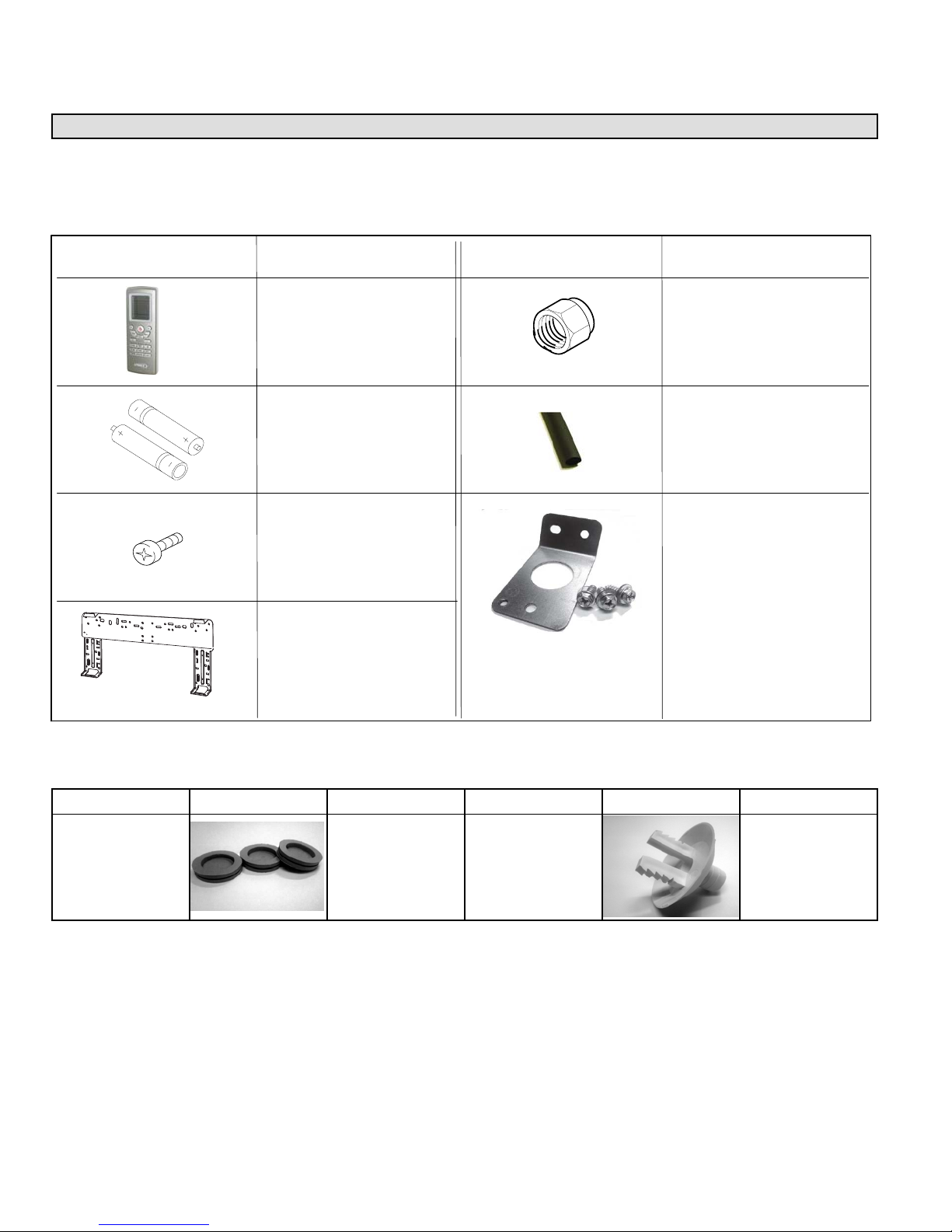
1 — ASSEMBLED INDOOR UNIT
The assembled indoor unit will include the following items:
Part Picture
Part Name
Remote control (1 each)
Batteries (AAA)
(2 each)
Wall mounting bracket
screws (5 each)
Wall mounting bracket
(1 each)
Part Picture
Name Name
1/4” flare nut (45º-degree
SAE style) for small line
(1 each)
Foam tube insulation
(for condensate line at
tached to indoor unit)
Cable routing guide with
mounting hardware (in
cluded with 18, 24 and
30kBtu. The -09 and 12
kBtu sizes include factory
installed cable routing
guide.
1 — ASSEMBLED OUTDOOR UNIT
The assembled outdoor unit will include the following items which are located with the unit:
Parts
Auxiliary drain
hole plugs (heat
pump only)
MS8C / MS8H (208-230V)
Figure Quantity Parts Figure Quantity
1 - 3
Drain plug
(heat pump only)
Page 2
1
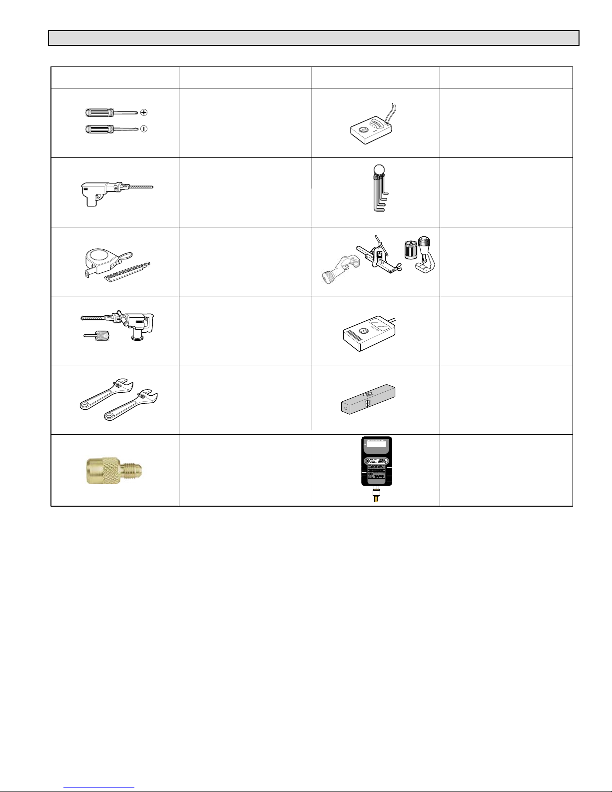
Required Tools and Supplies
INSTALLATION TOOLS
Tool Picture
Tool Name
Screw driver
Electric drill
Measuring tape and
knife
Hole core drill
Tool Picture
Tool Name
Multimeter
Allen wrench set
(metric)
Flaring tool and pipe
cutter
Refrigerant leak detector
or a bottle of soapy water
Adjustable wrench
500
Level
A 5/16” female flare to
1/4” male flare adapter
(order Lennox catalog
Micron gauge
number Y0576)
SUPPLIES
The following field-provided supplies may be required for installation
* Line set (see table 9 for requirements)
* Foam insulation (line set and condensate line)
* UV rated protective tape (used to maintain positioning of bundle). Bundle consists of line set, condensate line and wiring
between indoor and outdoor units.
* UV rated cable ties
* Outdoor unit pad
* Outdoor disconnect switch (indoor unit disconnect switch may be required by local code)
* Cable (4-conductor). All need to be rated either 208-240V and sized per NEC).
NOTE — Stranded wire must be used to connect the outdoor unit to the indoor unit. The stranded wire is necessary to ensure
proper system communication and operation.
* Plastic wall screw anchors
* Exterior wall channel (optional)
* Wall sleeve or PVC tubing material to field fabricate a wall sleeve for line set, condensate line and wiring (utility bundle).
Page 3
Corp. 1244-L9
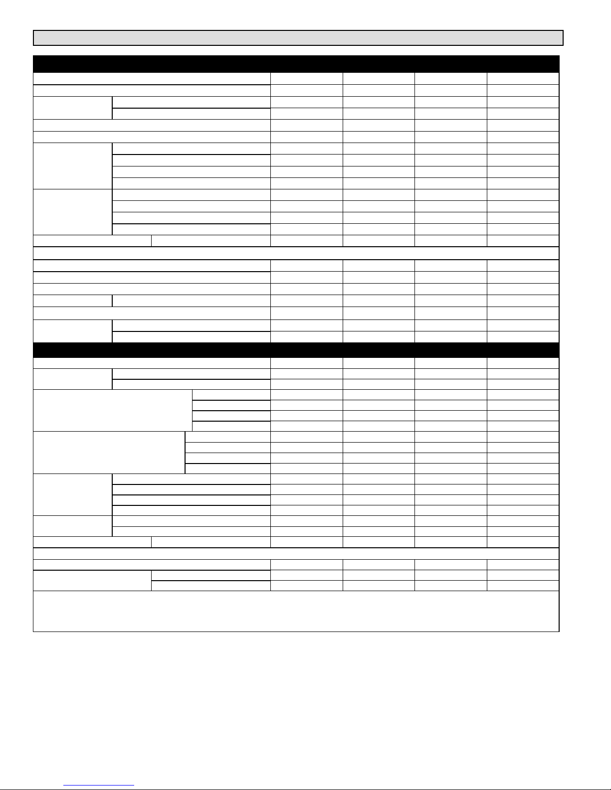
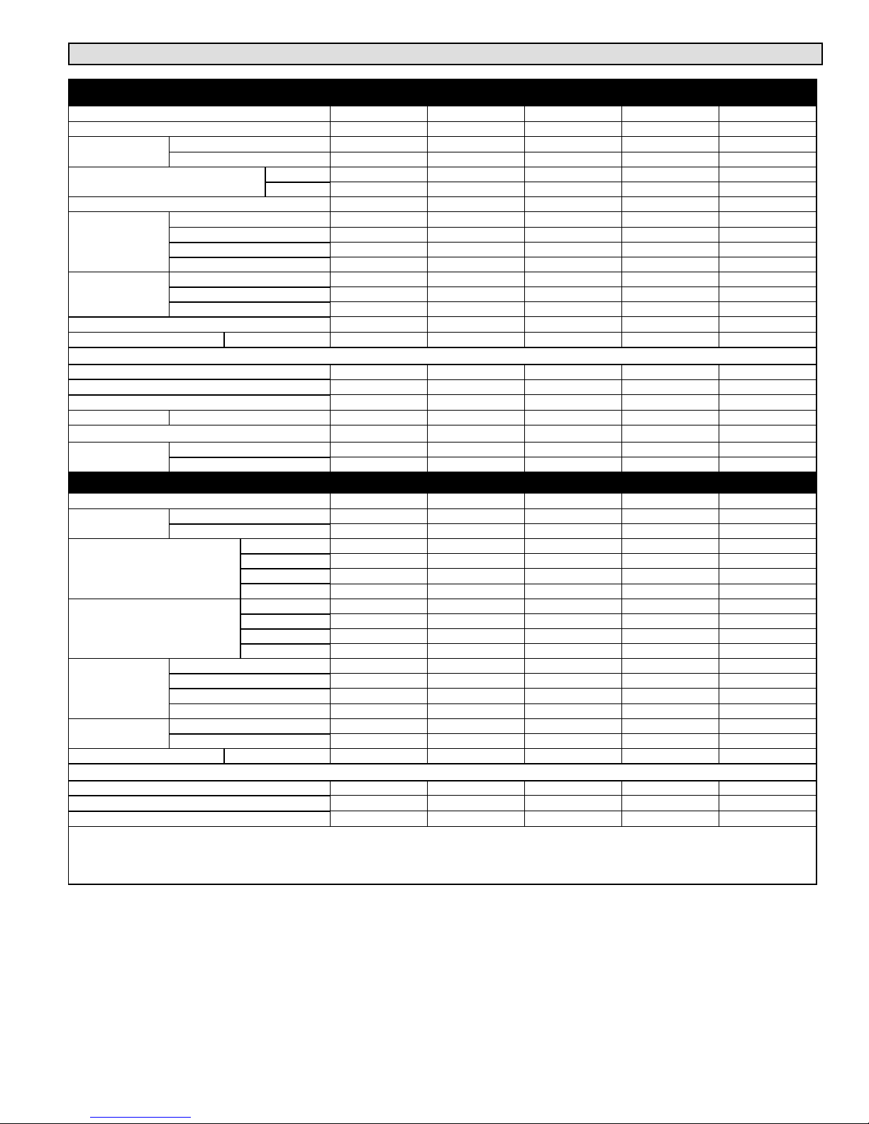
Specifications - AIR CONDITIONER SYSTEMS
OUTDOOR UNIT
Nominal Tonnage 0.75 1 1.5 2
Outdoor Unit Model No. MS8CO09P MS8CO12P MS8CO18P MS8CO24P
Connections (in.)
Ambient Temperature Operating Range °F 0 109 0 109 5 109 5 109
1
Refrigerant (R410A) furnished 2 lbs. 14 oz. 2 lbs. 14 oz. 3 lbs. 1 oz. 3 lbs. 9 oz.
Outdoor Coil
Outdoor Fan
Motor
Shipping Data lbs. Outdoor Unit 91 97 110 132
ELECTRICAL DATA
2
Maximum overcurrent protection (amps) 15 15 20 25
Compressor Rated load amps 27.2 6.5 9.7 11
4
Compressor Power Input (W)
Outdoor Fan
Motor
Connections (in.)
Indoor Blower Air Volume (cfm)
Indoor Blower RPM
Indoor Coil
Indoor Blower
Shipping Data lbs. Indoor Unit 31 29 38 47
Line voltage data 60 hz 1ph 208/230V 208/230V 208/230V 208/230V
ELECTRICAL DATA
Line voltage data 60 hz 1ph 208/230V 208/230V 208/230V 208/230V
NOTE Extremes of operating range are plus 10% and minus 5% of line voltage.
1
Refrigerant charge sufficient for 15 ft. of line set.
2
HACR type circuit breaker or fuse.
3
Refer to National or Canadian Electrical Code manual to determine wire, fuse and disconnect size requirements.
4
Rated Input
Small line o.d. flare 1/4 1/4 1/4 1/4
Large line o.d. flare 3/8 3/8 1/2 5/8
Net face area sq. ft. 4.08 4.49 5.96 7.66
Tube diameter in. 1/4 3/8 1/4 1/4
Number of rows 2 2 2 2
Fins per inch 20 20 20 20
Diameter in. 153/4 153/4 201/2 213/4
No. of blades 3 3 3 3
Cfm 940 940 1885 2355
Rpm 680/900 680/900 800 800
3
Minimum circuit ampacity 10 10 13 16
1075 860 1200 1420
Rated load amps 0.13 0.13 0.28 1.1
Output (W) 40 30 60 90
MATCHING INDOOR UNIT
Indoor Unit Model No. MS8CI09P MS8CI12P MS8CI18P MS8CI24P
Small line o.d. flare 1/4 1/4 1/4 1/4
Large line o.d. flare 3/8 3/8 1/2 5/8
Turbo 305 335 500 590
High 275 275 460 470
Medium 255 255 385 410
Low 220 220 325 355
Turbo 1260 1330 1500 1500
High 1100 1100 1200 1200
Medium 950 950 1050 1050
Low 750 750 900 900
Net face area sq. ft. 1.65 1.65 2.33 3.23
Tube diameter in. 1/4 1/4 1/4 1/4
Number of rows 2 2 2 2
Fins per inch 20 20 20 18
Diameter x Length in. 3.6 x 25.4 3.6 x 25.4 3.9 x 28 3.9 x 30
Type Crossflow Crossflow Crossflow Crossflow
Rated Load Amps 0.20 0.20 0.32 0.24
Output (W) 20 20 20 60
MS8C / MS8H (208-230V)
Page 4
Specifications - HEAT PUMP SYSTEMS
OUTDOOR UNIT
Nominal Tonnage 0.75 1 1.5 2 2.5
Outdoor Unit Model No. MS8HO09P MS8HO12P MS8HO18P MS8HO24P MS8HO30P
Connections
(in.)
Ambient Temperature Operating
Range °F
1
Refrigerant (R410A) furnished 2 lbs. 14 oz. 2 lbs. 14 oz. 3 lbs. 1 oz. 3 lbs. 9 oz. 5 lbs. 5 oz.
Outdoor Coil
Outdoor Fan
Motor
Shipping Data lbs. Outdoor Unit 11 0 119 110 135 164
ELECTRICAL DATA
Line voltage data 60 hz 1ph 208/230V 208/230V 208/230V 208/230V 208/230V
2
Max. overcurrent protection (amps) 15 15 20 25 30
Compressor Rated load amps 7.2 6.5 9.7 11 13.5
4
Compressor Power Input (W)
Outdoor Fan
Motor
Connections
(in.)
Indoor Blower Air Volume
(cfm)
Indoor Blower RPM (Cooling/
Heating)
Indoor Coil
Indoor Blower
Shipping Data lbs. Indoor Unit 37 37 38 47 60
ELECTRICAL DATA
Line voltage data 60 hz 1ph 208/230V 208/230V 208/230V 208/230V 208/230V
NOTE Extremes of operating range are plus 10% and minus 5% of line voltage.
1
Refrigerant charge sufficient for 15 ft. of line set.
2
HACR type circuit breaker or fuse.
3
Refer to National or Canadian Electrical Code manual to determine wire, fuse and disconnect size requirements.
4
Rated Input
Small line o.d. flare 1/4 1/4 1/4 1/4 1/4
Large line o.d. flare 3/8 3/8 1/2 5/8 5/8
Cooling 0 109 0 109 14 109 14 109 5 109
Heating –5 75 –5 75 19 75 19 75 17 75
Net face area sq. ft. 4.08 4.49 5.96 7.66 7.66
Tube diameter in. 1/4 3/8 1/4 1/4 5/16
Number of rows 2 2 2 2 2
Fins per inch 20 20 20 20 18
Diameter in. 153/4 153/4 201/2 213/4 213/4
No. of blades 3 3 3 3 3
Cfm 940 940 1885 2355 2355
Rpm 680/900 680/900 800 800 830
3
Minimum circuit ampacity 10 10 13 16 20
860 860 1200 1420 2450
Rated load amps 0.13 0.13 0.28 1.1 0.45
Output (W) 30 30 60 90 90
MATCHING INDOOR UNIT
Indoor Unit Model No. MS8HI09P MS8HI12P MS8HI18P MS8HI24P MS8HI30P
Small line o.d. flare 1/4 1/4 1/4 1/4 1/4
Large line o.d. flare 3/8 3/8 1/2 5/8 5/8
Turbo 306 335 500 590
High 277 277 459 470 705
Medium 253 253 383 410 675
Low 218 218 324 355 645
Turbo 1260/1320 1330/1350 1500/1500 1500/1450
High 1100/1200 1100/1170 1200/1250 1200/1150 1410/1410
Medium 950/1100 950/1050 1050/1150 1050/1020 1280/1280
Low 750/950 750/950 900/1050 900/950 1200/1200
Net face area sq. ft. 1.65 1.65 2.33 3.23 14.8
Tube diameter in. 1/4 1/4 1/4 1/4 1/4
Number of rows 2 2 2 2 2
Fins per inch 20 20 20 18 18
Diameter x Length in. 3.6 x 25.4 3.6 x 25.4 3.9 x 28 3.9 x 30 4.25 x 20.5
Type Crossflow Crossflow Crossflow Crossflow Crossflow
Rated Load Amps 0.20 0.20 0.32 0.24 0.40
Output (W) 20 20 20 60 40
Page 5
Corp. 1244-L9
Model Number Identification
−
8
Series Type
MS = Mini-Split
Series
Unit Type
CI = Air Conditioner Indoor Unit
HI = Heat Pump Indoor Unit
CO = Air Conditioner Outdoor Unit
HO = Heat Pump Outdoor Unit
CIMS
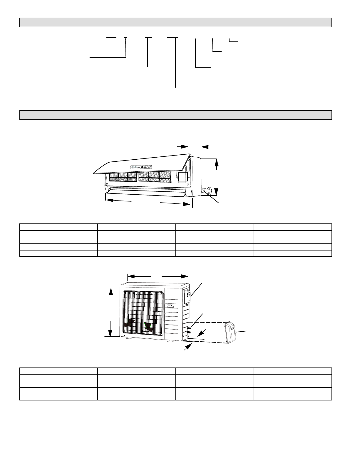
Unit Dimensions - inches (mm) and Weights
INDOOR UNIT
A
TABLE 1. INDOOR UNIT DIMENSIONS — INCHES
Model Size A B C
-09 and -12 33-3/8 10-7/8 7
-18 37 11-3/4 8
-24 39-3/4 12-3/8 8-5/8
-30 53-1/8 12-7/8 10
−09
P
1 A
Minor Revision
Number of Zones
1 = single zone
Voltage
L = 115V-1phase-60hz
Capacity - BTUH
09 = 9,000
12 = 12,000
C
C
B
LINE SET, CONDENSATE
DRAIN AND ELECTRICAL
CONNECTIONS
Model Size A B C
-09 21-1/4 30 12-5/8
-12 23-1/4 30 12-5/8
-18 27-5/8 35 15-5/8
-24 and -30 31-1/8 36 16-7/8
MS8C / MS8H (208-230V)
B
ELECTRICAL CONNECTIONS (UNDER COVER)
A
LINE SET CONNECTIONS
(COVER REMOVED)
C
TABLE 2. OUTDOOR UNIT DIMENSIONS — INCHES
Page 6
LINE SET COVER
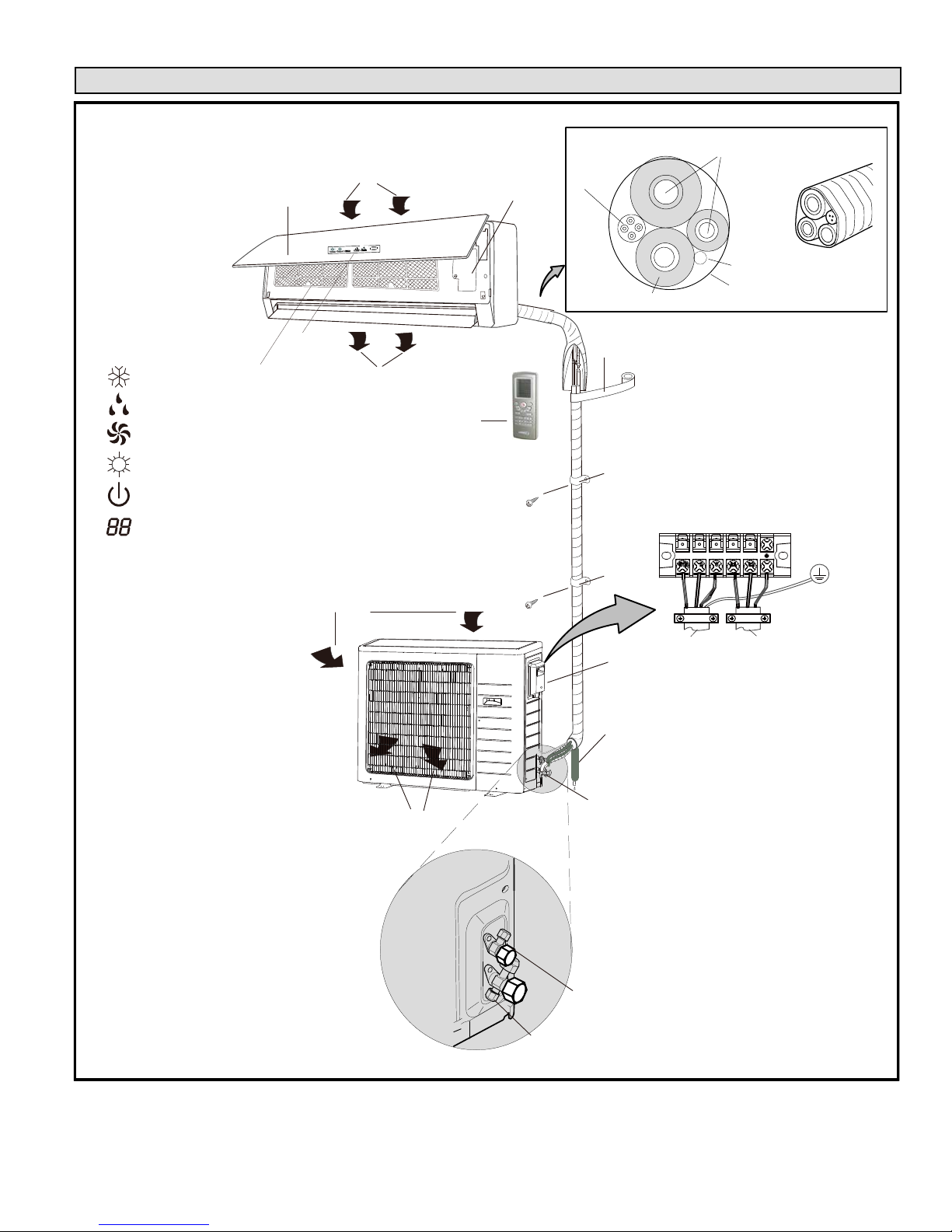
TABLE 3. OUTDOOR UNIT DIMENSIONS — INCHES (MILLIMETERS)
Typical System Component Setup
TYPICAL COMPONENT SETUP
RETURN AIR
B
INDOOR UNIT
DISPLAY
D
INDICATORS
COOL
DRY
FAN
HEAT
RUN
TEMPERATURE SETTING,
INDOOR AMBIENT TEMPERATURE
OR ERROR CODE
NOTE — temperature can be
displayed in either Fahrenheit or
Celsius.
D
C
SUPPLY AIR
AIR IN
A
WIRELESS REMOTE
CONTROL
OUTDOOR UNIT (AIR
CONDITIONER OR HEAT
PUMP)
E
G
K
L
TAPE
H
REFRIGERANT LINE SET, CONDENSATE LINE
F
AND INDOOR / OUTDOOR CABLE
IMPORTANT - The refrigerant
metering device for this system is
located in the outdoor unit. This
makes it necessary to insulate
the refrigerant lines individually to
prevent sweating.
OUTDOOR UNIT
TERMINAL BLOCK
A. Remote control
B. Front panel
C. Filters
D. Guide louver with display
E. Line set (wrapped in foam insulation)
F. UV-rated tape (field-provided)
G. Wiring (field-provided)
H. Condensate drain line (field-provided)
(wrapped in foam insulation). Recommend
installation of a vent when making long
horizontal runs on condensate line.
I. 3-way service valve
J. Access cover for power and control wiring
connections
K. Indoor unit wiring connections (under
access plate)
AIR OUT
FIGURE 1
J
H
I
2-WAY SHUT-OFF VALVE
3-WAY SERVICE VALVE
(FLARE CONNECTION)
TO INDOOR
UNIT
TO POWER
SUPPLY
Page 7
Corp. 1244-L9
II. INSTALLATION
IMPORTANT INSTALLER INFORMATION
* Confirm proper slope and routing of condensate lines to ensure moisture is drained away from the indoor unit (see
procedure starting on page 12)
* Confirm proper insulating, taping and bundling of refrigeration lines, main power lines and drain line (see procedure
starting on pages 25).
General
The MS8 air conditioners and heat pumps are matched with
an indoor evaporator unit to create a ductless system that
uses HFC-410A refrigerant.
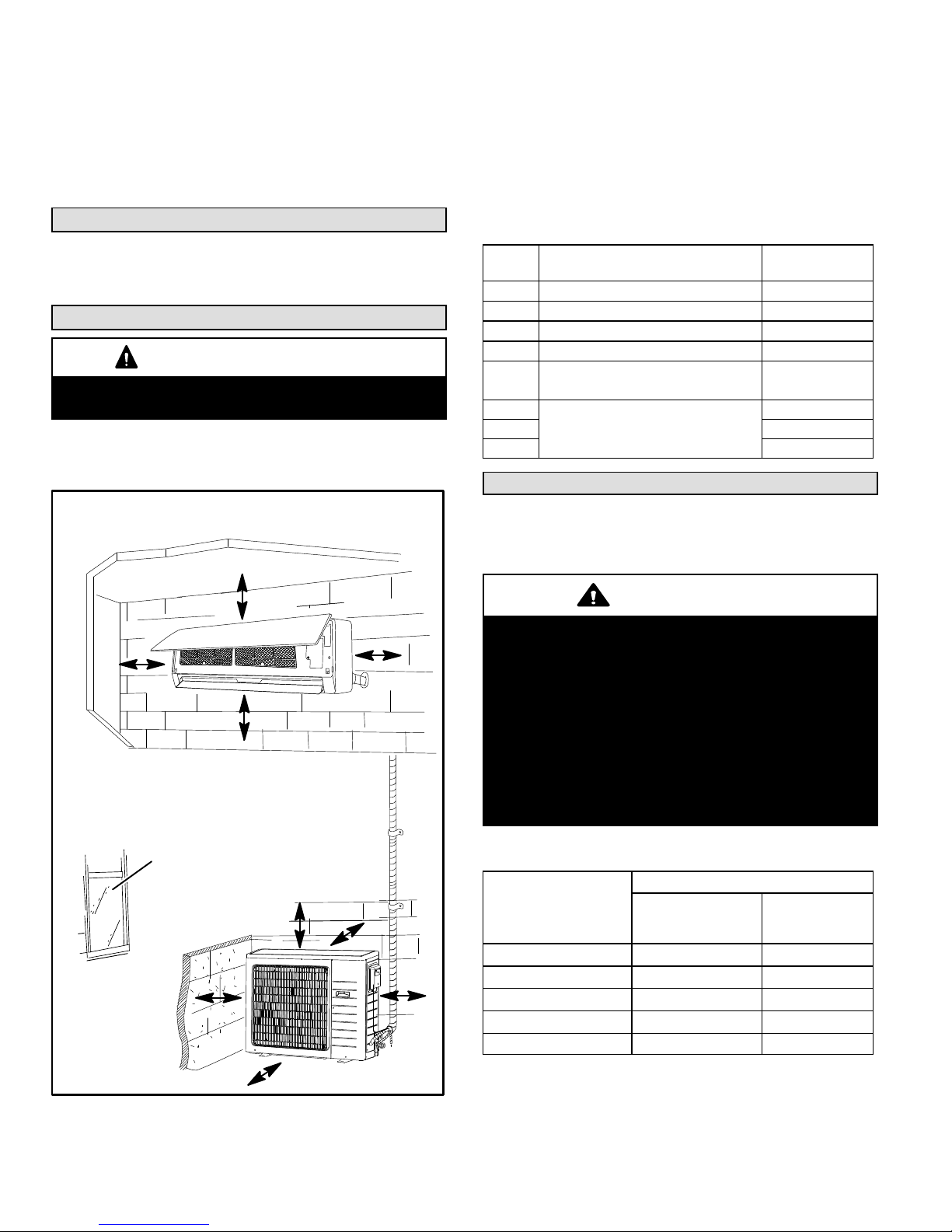
Clearances
CAUTION
In order to avoid injury, take proper precaution when lifting
heavy objects.
SYSTEM CLEARANCES
Refer to figure 2 for mandatory installation clearance
requirements.
MINIMUM INSTALLATION CLEARANCES
A
C
D
B
TABLE 4
MINIMUM SYSTEM CLEARANCES
ID Location
A Clearance between unit and ceiling. 6 in. (152 mm)
B Clearance between unit and floor. 6 ft.(1829 mm)
C / D Clearance to the right and left of unit. 6 in. (152 mm)
E Clearance above unit. 2 ft. (610 mm)
Clearance between air inlet and
F
structure.
G
Clearance between unit and
H 4 ft. (1219 mm)
structures
I 12 in. (305 mm)
Clearance
Required
12 in. (305 mm)
12 in. (305 mm)
Torque Requirements for Caps and Fasteners
When servicing or repairing HVAC components, ensure the
fasteners are appropriately tightened. Table 5 provides
torque values for fasteners.
IMPORTANT
Only use Allen wrenches of sufficient hardness (50Rc Rockwell Harness Scale minimum). Fully insert the
wrench into the valve stem recess.
Service valve stems are factory-torqued (from 9 ft-lbs for
small valves, to 25 ft-lbs for large valves) to prevent
refrigerant loss during shipping and handling. Using an
Allen wrench rated at less than 50Rc risks rounding or
breaking off the wrench, or stripping the valve stem
recess.
See the Lennox Service and Application Notes #C-08-1
for further details and information.
INSTALL UNIT AWAY
FROM WINDOWS
E
I
H
FIGURE 2
MS8C / MS8H (208-230V)
TABLE 5
TORQUE REQUIREMENTS
Recommended Torque
F
G
Parts
Service valve cap 8 ft.- lb. 11
Sheet metal screws 16 in.- lb. 2
Machine screws #10 27 in.- lb. 3
Compressor bolts 7 ft.- lb. 10
Gauge port seal cap 8 ft.- lb. 11
*The United States customary system (also called American system) is a
system of measurement commonly used in the United States. This system
is based on the British Imperial System.
United States
Customary
System*
Metric
(Newton Meter)
Page 8
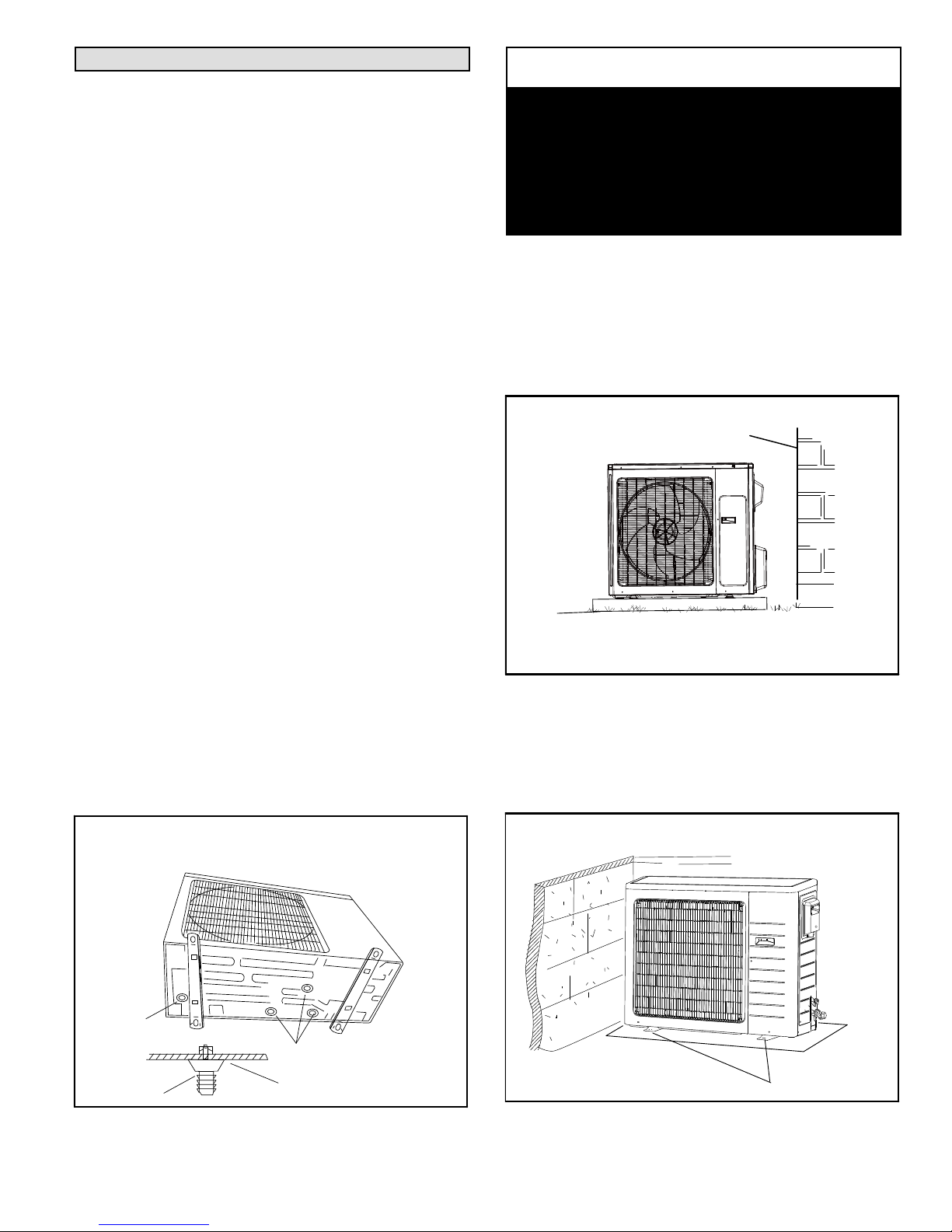
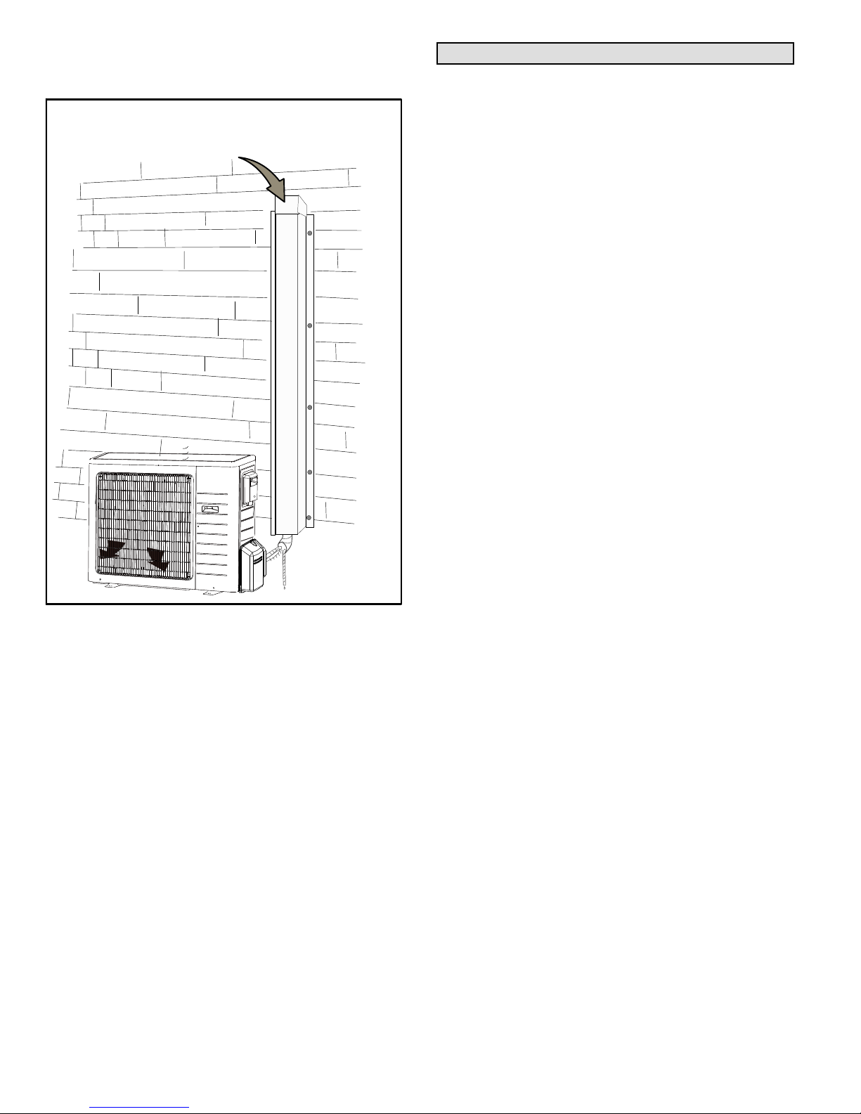
Setting Outdoor Unit
OUTDOOR UNIT POSITIONING CONSIDERATIONS
(AIR CONDITIONER OR HEAT PUMP)
Consider the following when positioning the unit:
* Some localities are adopting sound ordinances based
on the unit's sound level registered from the adjacent
property, not from the property where the unit is
installed. Install the unit as far as possible from the
property line.
* When possible, do not install the unit directly outside a
window. Glass has a very high level of sound
transmission. For proper placement of unit in relation
to a window see the provided illustration in figure 2.
* Install unit level or, if on a slope, maintain slope
tolerance of 2 degrees [or 2 inches per 5 feet (50 mm
per 1.5 m)] away from building structure.
* Install the unit high enough above the ground or roof to
allow adequate drainage of defrost water and prevent
ice or snow build-up (required for heat pumps).
* In heavy snow areas, do not locate the unit where
drifting will occur. The unit base should be elevated
above the depth of average snows.
* When installed in areas where low ambient
temperatures exist, locate unit so winter prevailing
winds do not blow directly onto outdoor unit.
* Locate unit away from overhanging roof lines which
would allow water or ice to drop on, or in front of, coil
or into unit.
CONDENSATE DRAINAGE REQUIREMENT
(HEAT PUMP ONLY)
Condensate formed during the heating and defrost
processes must be drained from heat pump units. Drain
holes are provided in the base of the units to ensure proper
drainage. Heat pumps must be raised when installed on a
concrete pad or the ground to allow drainage to occur. If the
heat pump unit is installed on a wall mounting bracket,
insert the provided drain connector into one of the 1 inch
(25mm) drain holes and attached a field-provided insulated
drain hose to the connector. Use the provided rubber plugs
to cover any unused drain holes (figure 3).
NOTICE
Roof Damage!
This system contains both refrigerant and oil. Some
rubber roofing material may absorb oil. This will cause
the rubber to swell when it comes into contact with oil.
The rubber will then bubble and could cause leaks.
Protect the roof surface to avoid exposure to refrigerant
and oil during service and installation. Failure to follow
this notice could result in damage to roof surface.
SLAB OR ROOF MOUNTING
Install the unit a minimum of 4 inches (102 mm) above the
roof or ground surface to avoid ice build-up around the unit.
Locate the unit above a load bearing wall or area of the roof
that can adequately support the unit. Consult local codes
for rooftop applications (figure 4).
SLOPE TOLERANCE
BUILDING STRUCTURE
GROUND
LEVEL
Install unit level or maintain slope tolerance of 2
degrees (or 2 inches per 5 feet [50 mm per 1.5 m])
away from building structure.
FIGURE 4
SECURING OUTDOOR UNIT TO SLAB OR FRAME
If the outdoor unit is installed on a field-provided slab or
frame, use lag bolts or equivalent to secure the outdoor unit
to the slab or frame (figure 5).
CONDENSATE DRAINAGE (HEAT PUMPS
ONLY -- UNIT INSTALLED ON FIELD-PROVIDED
WALL-MOUNTING FRAME)
DRAIN
CONNECTOR
DRAIN
CONNECTOR
DRAIN PLUGS
CHASSIS
FIGURE 3
Page 9
SECURING OUTDOOR UNIT TO SLAB
FOUR
FIELD-PROVIDED
ANCHOR BOLTS
FIGURE 5
Corp. 1244-L9
PREVAILING WINDS (HEAT PUMP ONLY)
If unit coil cannot be installed away from prevailing winter
winds, a wind barrier should be constructed. Size barrier at
least the same height and width as outdoor unit. Install
barrier 12 inches minimum (305 mm) from the sides of the
unit in the direction of prevailing winds as illustrated.
PREVAILING WIND BARRIER
PREVAILING WINTER WINDS
WIND BARRIER
INLET AIR
12” (305 MM) MINIMUM DISTANCE
DISCHARGE AIR
FIGURE 6
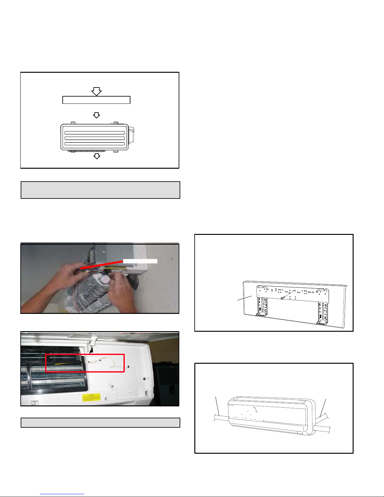
Repositioning Indoor Air Temperature
Sensor
The indoor temperature sensor may be installed in an
alternate location to facilitate shipping (figure 7). It is
recommend that the sensor is relocated to the proper
position shown in figure 8. Refer to the procedure on page
for removal of the front cover.
SHIPPING LOCATION
SENSOR
AVOID
1. Direct sunlight if possible.
2. Locating unit less than 3-1/4” (1 meter) away from
combustible materials and vapors.
3. Locating unit near heat sources which could affect
system performance.
DO:
1. Locate the indoor unit where the room can be uniformly
cooled. Install unit as high as possible on the wall for
best performance.
2. Select a wall location that can support the weight of the
unit.
3. Select a location where line set and condensate line will
have the shortest run to the outside of the structure.
4. Allow sufficient space around unit for proper operation
and maintenance.
5. Consider vertical rise between the indoor unit and
outdoor unit. Do not exceed the maximum vertical line
rise of the line set between the indoor unit and outdoor
unit (table 12).
6. Install the indoor unit a minimum of 36 inches (914 mm)
away from any antenna, power cords (lines), radio,
telephone, security system, or intercom. Electrical
noise and radio frequencies from any of these sources
may affect operation.
DETERMINING WALL MOUNTING BRACKET
LOCATION
1. Remove the wall mounting bracket from the indoor unit.
WALL MOUNTING BRACKET REMOVAL
FROM INDOOR UNIT
A. Remove the shipping screw that secures the
wall mounting bracket to the rear of the unit.
B. Remove bracket from rear panel of indoor unit.
FIGURE 7
CORRECT
LOCATION
FIGURE 8
Indoor Unit Placement and Preparation
INDOOR UNIT LOCATION
Minimum clearances must be maintained as specified in
figure 2. In addition, the following items should be
considered:
MS8C / MS8H (208-230V)
Page 10
REAR OF UNIT
FIGURE 9
2. Determine the optimal exit location for bundle (line set,
condensate line and wiring.
DETERMINING EXIT LOCATION
CONDENSATE/
REFRIGERANT
LINE EXIT LEFT
CONDENSATE/
REFRIGERANT LINE
EXIT LEFT REAR
CONDENSATE/
REFRIGERANT LINE
EXIT RIGHT REAR
(RECOMMENDED)
CONDENSATE/
REFRIGERANT
LINE EXIT RIGHT
FIGURE 10
NOTE — If opposite-side exit is preferred, see figure 18 to
switch condensate line and drain cap.
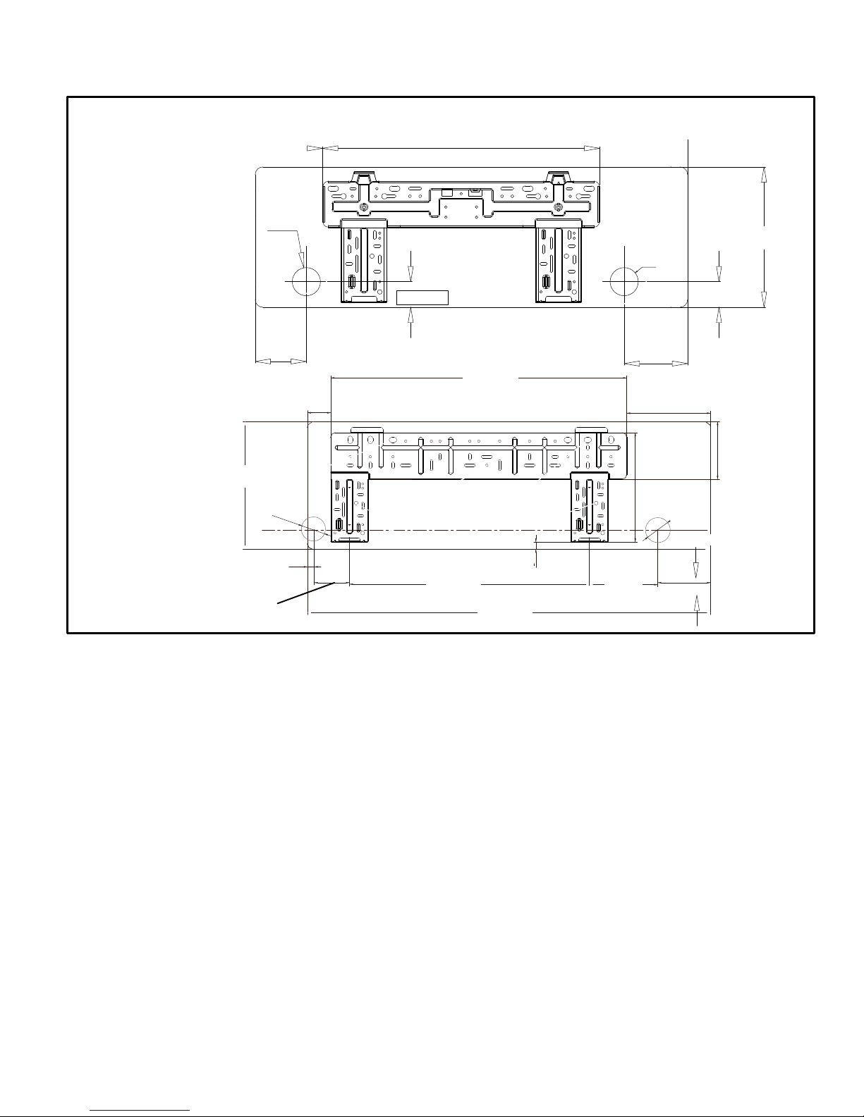
3. Use the wall mounting bracket as a template to
CONDENSATE / REFRIGERANT PIPING REAR EXIT LOCATIONS
2-3/16”
(55)
09 − 12 kBtu
determine the exit point for the line set, condensate line
and indoor / outdoor cable (figure 11).
21-5/16” (542)
2-3/16”
(55)
10-7/8”
(275)
18 kBtu
11-3/4”
(298)
3-1/4”
4”
(100)
2-3/16”
(55)
5/8” (16)
(82)
2-1/8”
(55)
2” (50)
22-3/16”
(563)
FIGURE 11
27-5/16”
(694)
5/8” (16)
33-1/4”
(945)
6-1/4”
(160)
5” (124)
7-3/4”
256
2-3/16”
(55)
(197)
2” (50)
1-3/4” (45)
4-7/8”
(124)
5-5/16”
(136)
Page 11
Corp. 1244-L9
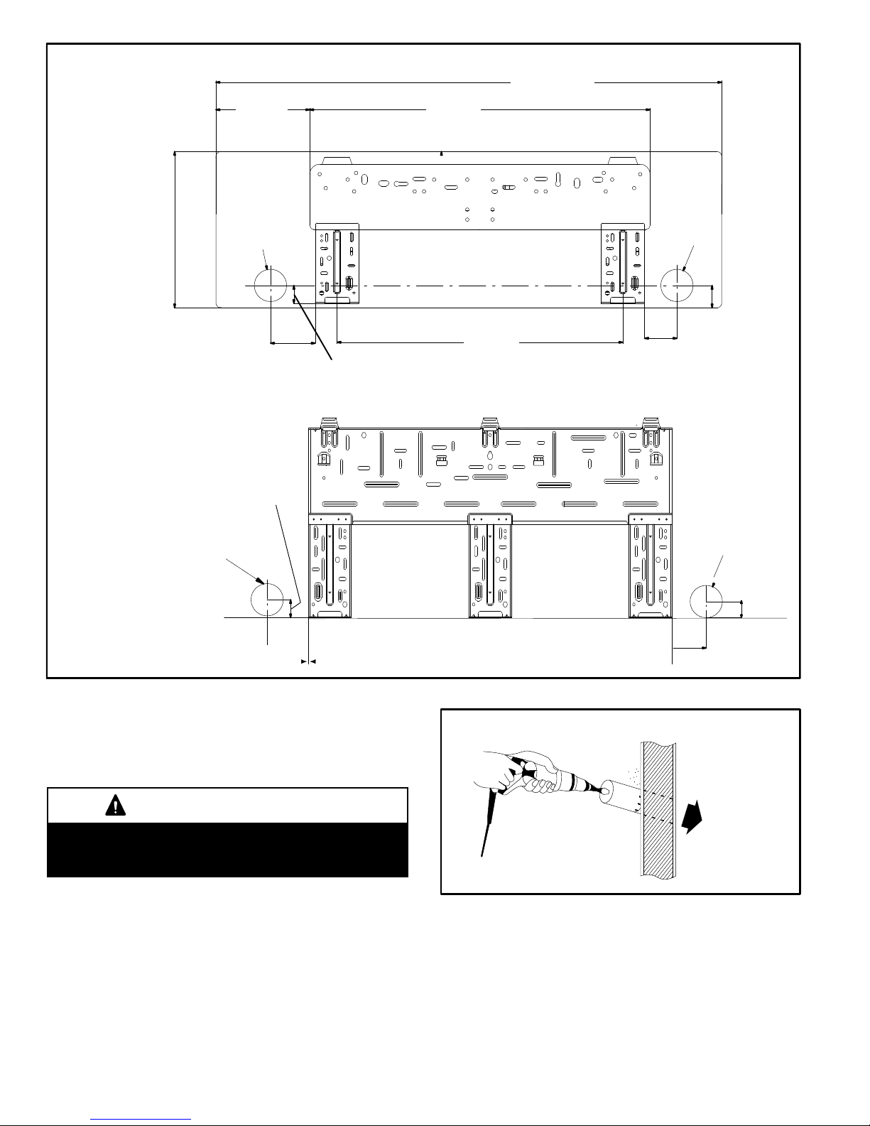
7-7/16”
(189)
40-1/8” (1018)
27 (685)
24 kBtu
30 kBtu
2-9/16”
(65)
2-9/16”
(65)
1” (25)
3-1/2”
(90)
4”
(102)
1-7/16” (36)
22-5/8”
(575)
2-1/2”
(65)
2-9/16”
(65)
4”
(102)
1-3/4”
(45)
2-9/16”
(65)
1“ (25)
INSTALLING WALL SLEEVE
1. Prior to making the hole, check to ensure that neither
studs nor plumbing are directly located behind the hole
location.
CAUTION
Electric Shock Hazard. Can cause injury or death. Avoid
location where electric wiring or conduits may be present
inside the wall.
2. Use either a sabre saw, key hole saw or hole-cutting
drill attachment to cut a 2-3/16-inch (55 mm) diameter
hole in the wall. Hole should be at a slight downward
slant - 3/16” to 3/8” (5 to 10 mm) to the outdoor side.
MS8C / MS8H (208-230V)
FIGURE 12
BORING HOLE FOR WALL SLEEVE
INSIDE
OUTSIDE
FIGURE 13
3. Measure the thickness of the wall from the inside edge
to the outside edge and cut a field-provided PVC pipe
Page 12
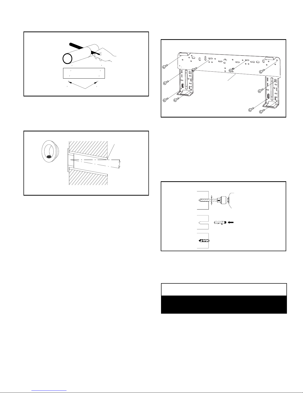
at a slight angle 1/4” (6 mm) shorter than the thickness
of the wall.
CUTTING PVC FOR WALL SLEEVE
CUT PVC FOR WALL SLEEVE AT SLIGHT ANGLE
FIGURE 14
4. Place a field-provided plastic cover over the end of the
pipe that will be visible from the inside wall and insert
the pipe in the wall.
PVC WALL SLEEVE INSTALLATION
PVC PIPE
SLIGHT
PLASTIC COVER
(FIELD PROVIDED)
INSIDE
WALL
ANGLE
OUTSIDE
NOTE
— It is important to use all screws provided to secure
the wall mounting bracket to the wall. Additional holes may
be drilled through the metal wall mounting bracket to better
secure wall bracket to wall studs.
SECURING WALL MOUNTING BRACKET TO WALL
WALL MOUNTING
BRACKET
FIGURE 16
4. The wall mounting bracket must be installed flush
against the wall so that the indoor unit will be flush after
installation. Any space between the wall and unit will
cause noise and vibration.
5. The wall mounting bracket must be installed
horizontally level on the wall.
6. If the wall is made of brick, concrete or other similar
material, then drill pilot holes in the wall. Insert
field-provided plastic anchors for mounting screws.
MASONRY APPLICATIONS
FIGURE 15
SECURE WALL MOUNTING BRACKET TO WALL
Determine that wall will support the weight of the indoor
unit. See table 1 for indoor unit weight. Install the wall
mounting bracket so that is is correctly positioned
horizontally and vertically. The indoor unit must be installed
level on the wall to allow proper condensate drainage.
1. Use a carpenter's level or tape measure to verify the
wall mounting bracket is horizontally level.
2. Secure the wall mounting bracket to the wall using the
provided screws. If possible, align the rear panel screw
holes with wall stud locations marked on the wall.
HINT
— Use the wall mounting bracket as a template to
mark locations where screws will be used.
3. Secure the wall mounting bracket to the wall using as
many screws into studs as possible. All other screws
must be secured using plastic wall anchors.
DRILL PILOT HOLES
USE ANCHORS
INSTALL ANCHORS
FIGURE 17
CONDENSATE DRAIN CONFIGURATION
If the condensate line needs to be moved, use the following
procedure to change the drain line exit location.
NOTICE
Care must be taken when moving the condensate line to
the opposite position to prevent damaging the
condensate line or connector.
Page 13
Corp. 1244-L9
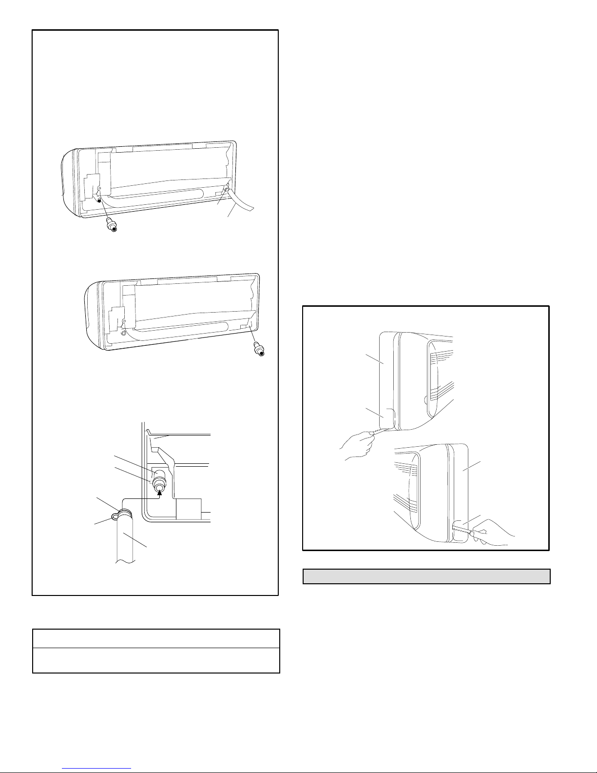
CHANGING CONDENSATE DRAIN LOCATION
(IF NECESSARY)
1. Locate the condensate line and the drain cap
located on unit.
2. Remove the clamp which secures the condensate
line to the drain outlet and pull the line to remove it.
3. Apply moderate force to pull off the drain cap from
the unit.
REAR VIEW OF UNIT
DRAIN CAP
CLAMP
CONDENSATE LINE
4. Re-install the drain cap on the opposite side
drain outlet.
REAR VIEW OF UNIT
1. Confirm proper slope (not less than 1/4 inch per foot)
and routing of condensate lines to ensure moisture is
drained away from the indoor unit (see page 12).
2. Drain should not have any droops or kinks that would
restrict condensate flow and shall be approved
resistant pipe.
3. Condensate drains should be ran as short as possible.
4. Once installation of drain is complete, pour water into
the evaporator drain pan to ensure proper condensate
drainage. If condensate will not properly drain from
evaporator pan, a condensate pump should be added
to system.
5. Confirm proper insulating, taping and bundling of
refrigeration lines, main power lines and drain line (see
page 16).
PREPARING INDOOR UNIT FRAME FOR LEFT- OR
RIGHT-SIDE EXIT OF UTILITY BUNDLE
1. Right- or Left-Side Utility Bundle Exit — Cut out the
corner of the right/left plastic cabinet with a hacksaw or
similar tool (A or B).
2. Right-Rear or Left-Rear Utility Bundle Exit — The
corner of the plastic cabinet does not need to be
modified.
DRAIN CAP
5. Slide the condensate line over the opposite
drain outlet and use the clamp to secure the
line.
REAR VIEW OF UNIT
DRAIN PAN
OUTLET
CLAMP HOOK
LATCH
CLAMP
CLAMP HOOK
CONDENSATE LINE
IMPORTANT — Keep horizontal runs of condensate line external
to unit as short as possible. Condensate line should be properly
sloped to ensure proper drainage.
FIGURE 18
CONDENSATE DRAIN LINE INSTALLATION
IMPORTANT !
Drain should have a slope of not less than ¼ inch per
foot and be approved corrosion resistance pipe.
LEFT- OR RIGHT-SIDE UTILITY EXIT
A
PLASTIC
CABINET
LEFT-SIDE
TUBING OUTLET
B
PLASTIC
CABINET
RIGHT-SIDE
TUBING OUTLET
FIGURE 19
Indoor Unit Cable Connections
NOTE — Stranded wire must be used to connect the
outdoor unit to the indoor unit. The stranded wire is
necessary to ensure proper system communication and
operation.
1. Route the cable (4-conductor, stranded wire, line
voltage, sized per National Electric Code) through the
wall sleeve. Refer to unit nameplate for rated voltage.
MS8C / MS8H (208-230V)
Page 14
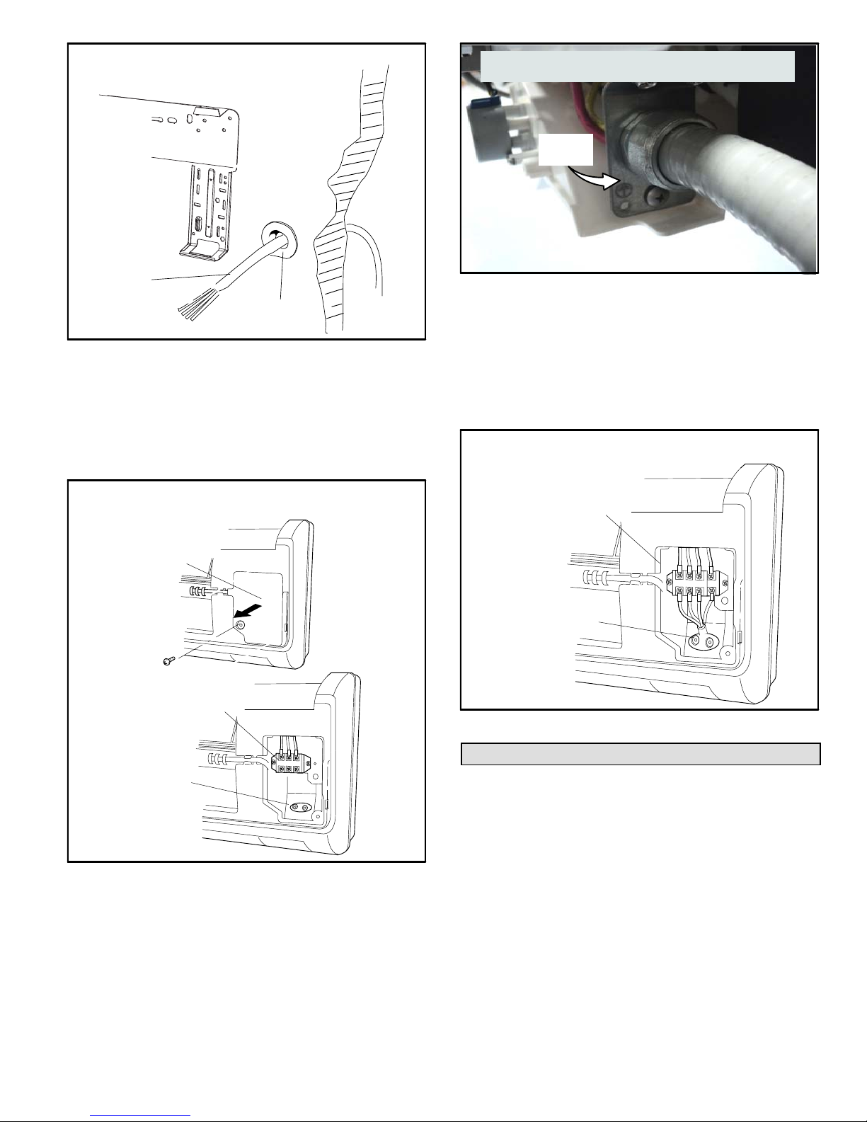
FEED CABLE THROUGH WALL
INDOOR UNIT WALL MOUNTING BRACKET
WALL
WIRING
FIELD-PROVIDED
PVC WALL SLEEVE
FIGURE 20
2. Make sure to provide a sufficient length of cable so that
connections are made to the unit before it is secured to
the wall mounting bracket.
3. Lift indoor unit front panel to access the control box
cover. Remove the screw(s) securing the cover plate.
Remove the plate.
TYPICAL INDOOR UNIT INDOOR UNIT) —
SECURING CABLE / WIRES
CONDUIT
ROUTING
GUIDE
REAR VIEW OF INDOOR UNIT
FIGURE 22
5. Strip the wire insulation to expose the stranded wire.
6. Tightly twist each wire end.
7. Terminal designations for the indoor unit terminal block
are illustrated in figure 30.
8. Use the provided strain relief plate to secure the
terminal block wiring.
TYPICAL INDOOR UNIT TERMINAL BLOCK
AND STRAIN RELIEF
ACCESSING THE INDOOR UNIT TERMINAL BLOCK
TYPICAL
INDOOR UNIT
CONTROL
BOX COVER
TERMINAL
BLOCK
TYPICAL WIRING
STRAIN RELIEF
FIGURE 21
4. Feed cable / wiring through conduit routing guide.
NOTE — A cable routing guide has been factory-installed.
TERMINAL
BLOCK
WIRING STRAIN RELIEF
FIGURE 23
Securing Indoor Unit to Wall Mounting Bracket
1. Shape the refrigerant line set so that it can be guided
either out the back of the indoor unit or through either
side of the indoor unit frame, then through the wall
sleeve to the outside unit.
2. Use field-provided tape to bundle the cable, refrigerant
line set and condensate line together as shown in figure
1.
3. Feed the bundle through the wall sleeve and slide
indoor unit onto upper mounting hooks.
Page 15
Corp. 1244-L9
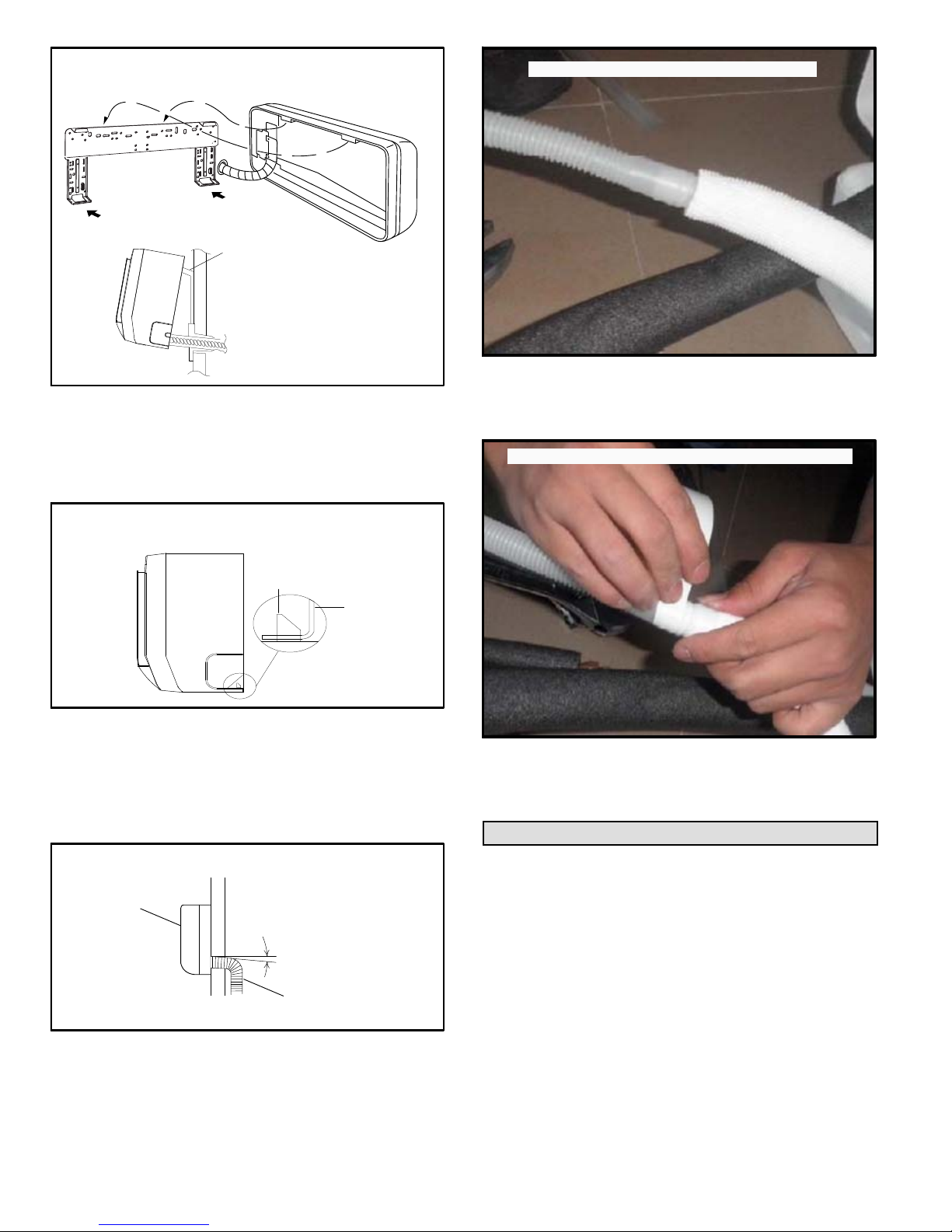
FEED BUNDLE THROUGH WALL SLEEVE
UPPER MOUNTING
HOOKS
PASS BUNDLE
THROUGH WALL
FIGURE 24
CONNECTING CONDENSATE LINE
FIGURE 27
3. Use tape approved for waterproofing line
connections to secure the field-provided pipe to the
factory-installed condensate line.
1. Secure the indoor unit to the wall bracket using the
lower mounting hooks.
SECURE INDOOR UNIT TO WALL MOUNTING
BRACKET
LOWER MOUNTING
HOOKS
FIGURE 25
2. Carefully bend the bundle (line set, condensate line
and cable) to run along the outside wall toward the
outdoor unit. Downward slope of wall sleeve will ensure
proper condensate drainage.
INSTALLED INDOOR UNIT
INDOOR UNIT
SLOPE
TAPING CONDENSATE LINE CONNECTION
FIGURE 28
NOTE — Use a clean, dry cloth to wipe the indoor unit after
installation is complete to remove fingerprints. Do not use
wet cloth, cleansers or solutions.
Outdoor Unit Wiring Connections
In the U.S.A., wiring must conform with current local codes
and the current National Electric Code (NEC). In Canada,
wiring must conform with current local codes and the current
Canadian Electrical Code (CEC).
Refer to unit nameplate for minimum circuit ampacity and
maximum overcurrent protection size.
BUNDLE THROUGH
WALL SLEEVE
FIGURE 26
CONDENSATE LINE
1. Use the provided foam insulation to wrap the
factory-installed condensate line.
2. Connect indoor unit factory-installed condensate line
to field-provided condensate drain pipe.
MS8C / MS8H (208-230V)
MAIN SYSTEM CIRCUIT BREAKER AND OUTDOOR
UNIT DISCONNECT SWITCH
The main system circuit breaker and outdoor unit
disconnect switch should be sized per local codes and unit
requirements.
Local codes may require a disconnect between the indoor
and outdoor units.
INDOOR / OUTDOOR CABLE
Wiring must conform to local and national codes.
Page 16
NOTE — Stranded wire must be used to connect the
outdoor unit to the indoor unit. The stranded wire is
necessary to ensure proper system communication and
operation.
SUPPLY POWER
Size per unit nameplate and local and national codes.
COMMUNICATION
N(1)
23L1
OUTDOOR UNIT
L2
WIRING CONNECTIONS
1. Remove access panel.
2. Route all wiring to outdoor unit through the wire routing
plate.
3. Connect the control wiring and power supply wiring per
the figures that follow.
4. The unit must be grounded according to local codes.
5. Secure wiring using built-in wire strain relief.
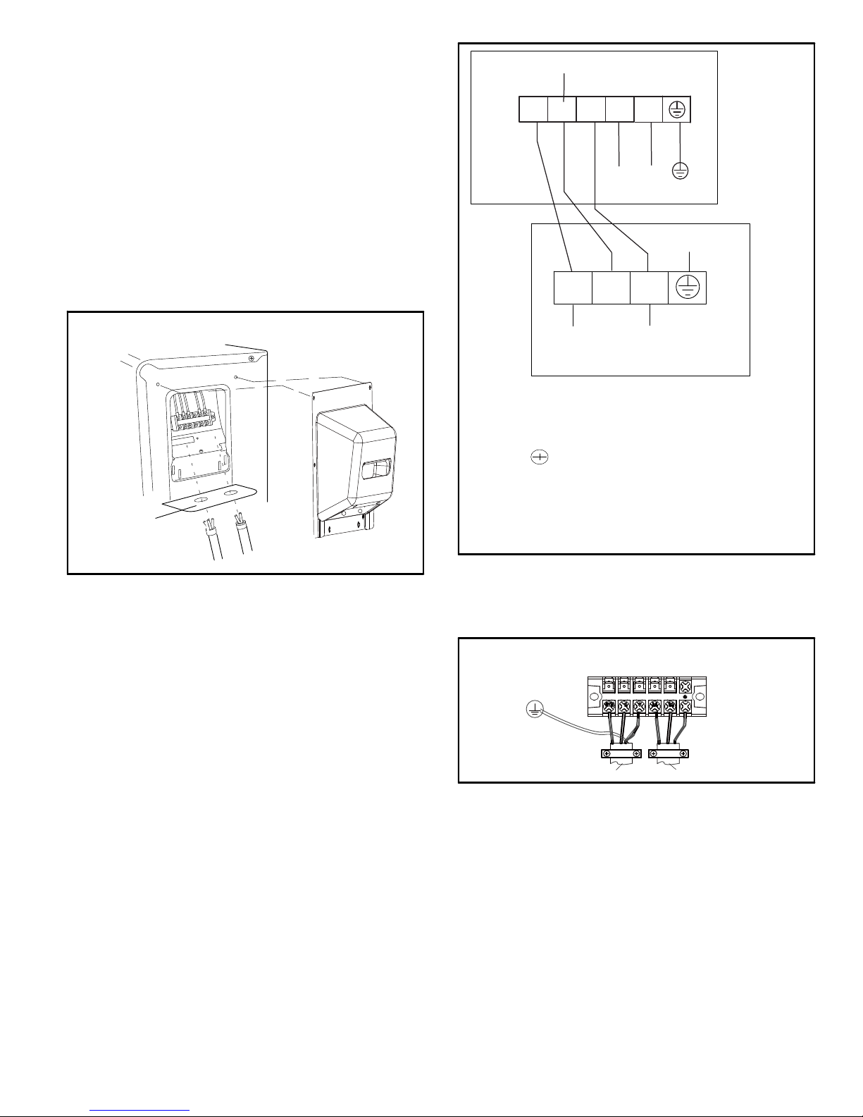
OUTDOOR UNIT ELECTRICAL CONNECTIONS
ROUTE WIRES
THROUGH
ROUTING
PLATE
ACCESS PLATE
FIGURE 29
L2
L1
POWER
GROUND
N(1)
(L1)
2
3
(L2)
(COMMUNICATION)
INDOOR UNIT
TERMINAL LEGEND
N(1) = L1
2 = Communication line
3 = L2
= Ground
IMPORTANT
Check indoor to outdoor field wiring to confirm (N) 1
from indoor goes to (N) 1 outdoor, terminal 2 from indoor
goes to terminal 2 outdoors and terminal 3 indoors goes
to terminal 3 in outdoor.
FIGURE 30
6. Connect the green/yellow ground wire to the ground
terminal.
7. Use the strain relief to secure the cabling (figure 31).
TYPICAL UNIT STRAIN RELIEF
OUTDOOR UNIT
TERMINAL BLOCK
TO INDOOR UNIT
TO POWER SUPPLY
FIGURE 31
WIRING DIAGRAM SYMBOLS AND COLOR CODES
The following tables identify the wiring color codes
and ground symbol used in the following wiring
diagrams.
Page 17
Corp. 1244-L9
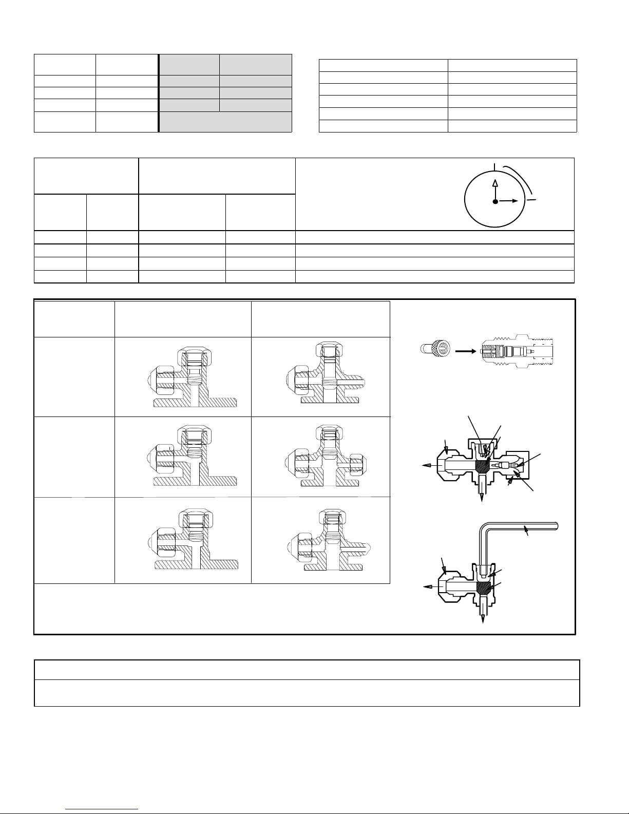
TABLE 6
WIRE COLOR CODES
CODE CODE COLOR
WH WHITE BN BROWN
YE YELLOW BU BLUE
RD RED BK BLACK
YEGN
YELLOW
GREEN
COLOR CODE
OR SYMBOL
Table 8. Valve Caps Torque Recommendations
COLOR
TABLE 7
SYMBOLS
SYMBOL PARTS NAME
L1 REACTOR (CHOKE)
PCB1-PCB2 PRINTED CIRCUIT BOARD
S10/S11S40/S70/S80/S90 CONNECTOR
SAT OVERLOAD
COMP COMPRESSOR
Outside Diameter Recommended Torque
Inches
1/4” 6.35 11 - 14-3/4 ft.- lb. 15 ~ 20 N*m
3/8” 9.52 26 - 29-1/2 ft.- lb. 35 ~ 40 N*m 1/2 turn
1/2” 12.70 44-1/4 - 48 ft.- lb. 60 ~ 65 N*m 7/8 turn
5/8” 16 51-5/8 - 55-1/4 ft.- lb. 70 ~ 75 N*m 1 full turn
Action
mm U.S. Metric
2-Way
Shut-Off Valve
No torque wrench available?
Finger tighten and use an
appropriately sized wrench to turn an
additional:
1/4 turn
3-Way
Service Valve
HOSE WITH
SCHRADER VALVE
CLOSED
Evacuating with a
vacuum pump
REQUIRES FIELD-PROVIDED 5/16”
FEMALE FLARE TO 1/4” MALE FLARE
ADAPTER.
FULLY
OPEN
FLARE CAP
Outdoor unit
running
TO LINE
SET
11
10
9
8
PUSH
VALVE CAP
12
1
2
3
4
5
7
6
3-WAY SERVICE
VALV E
OPEN POSITION
CLOSED POSITION
1/4 TURN
PIN
SERVICE
PORT
FULLY
OPEN
SERVICE
PORT CAP
TO OUTDOOR UNIT
Checking
pressure and
adding refrigerant
TO LINE
SET
FLARE CAP
TO OUTDOOR UNIT
ALLEN WRENCH
(5 MM)
OPEN POSITION
CLOSED POSITION
FIGURE 32
IMPORTANT !
To prevent stripping of the various caps, use an appropriately sized wrench and fit the wrench snugly over the cap before
tightening.
MS8C / MS8H (208-230V)
Page 18

Operating Service Valves
The large line service valve on the outdoor unit is used to
purge air, test for leaks, check operating pressures and add
refrigerant to system. The 3-way service valve is equipped
with a service port which has a factory-installed valve core.
Figure 32 provides information on how to access and
operate the 3-way service and 2-way shut-off valves.
IMPORTANT
To prevent stripping of the various caps, use an
appropriately sized wrench and fit the wrench snugly over
the cap before tightening.
Page 19
Corp. 1244-L9
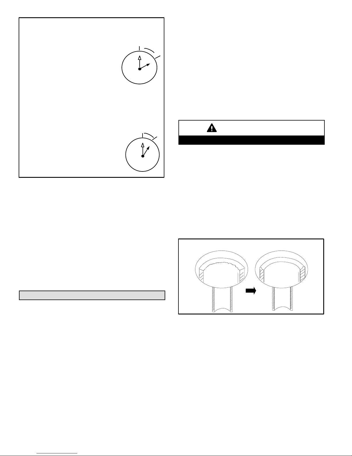
TIGHTENING SERVICE VALVE CAPS
To Access Service Port:
12
6
1/6
TURN
1
5
2
3
4
A service port cap protects the service port core
from contamination and serves as the primary
leak seal.
1. Remove service port cap with an
appropriately sized wrench.
2. Connect gauge set to service port.
3. When testing is complete, replace service
port cap and tighten as follows:
* With torque wrench: Finger tighten and torque cap per table
5.
* Without torque wrench: Finger tighten and use an appropri
ately sized wrench to turn an additional 1/6 turn clockwise.
10
9
11
8
7
Reinstall Stem Cap:
11
1/12
TURN
12
1
2
3
4
5
7
6
Stem cap protects the valve stem from damage
and serves as the primary seal. Replace the
stem cap and tighten as follows:
* With Torque Wrench: Finger tighten, then
torque cap per table 5.
* Without Torque Wrench: Finger tighten,
then use an appropriately sized wrench
to turn an additional 1/12 turn clockwise.
10
9
8
FIGURE 33
USING MANIFOLD GAUGE SET
When checking the system charge, only use a manifold
gauge set that features low-loss, anti-blow-back fittings.
Manifold gauge set used for HFC-410A refrigerant systems
must be capable of handling the higher system operating
pressures. The manifold gauges should be rated for:
* High side — Pressure range of 0 - 800 pound-force per
square inch gauge (psig)
* Low side — Use with 30” vacuum to 250 psig with
dampened speed to 500 psig
* Manifold gauge set hoses must be rated for use up to
800 psig of pressure with a 4000 psig burst rating.
connections and sizes as listed in table 12.
Seal and isolate the opening where the bundle (including
refrigerant lines) passes through so vibration is not
transmitted to the building. Pay close attention to line set
isolation during installation of any HVAC system. When
properly isolated from building structures (walls, ceilings.
floors), the refrigerant lines will not create unnecessary
vibration and subsequent sound. Line set must be
insulated.
LINE SET LENGTH AND ELEVATION
Capacity is based on standard line set length and maximum
allowable length and elevation (table 12).
Minimum line set length for all sizes is 10 feet (3 meters).
IMPORTANT
Mineral oils are not compatible with HFC-410A.
LINE SET CONNECTIONS
Line connections are made to the outdoor unit using
field-provided flare nuts.
Remove the service valve cover from the outdoor unit.
FLARING PROCEDURE
1. Use a tube cutter to cut the copper line set to the
required length. Cut the lines approximately 12” to 20”
(305 mm to 508 mm) longer than the estimated
required length.
2. Use a pipe reamer or file to remove burrs at the end of
the line set.
DE-BURRING LINE SET
BEFORE
AFTER
Line Set Requirements
This section provides information on installation of the
field-provided line set.
LINE SET INSTALLATION
Field piping consists of two lines from the outdoor unit to the
indoor unit. Use field-fabricated line set with flare
MS8C / MS8H (208-230V)
FIGURE 34
3. Remove flare nut from outdoor unit and slide it onto the
copper tube.
4. Use a flaring tool to flare the end of the copper tube.
Page 20
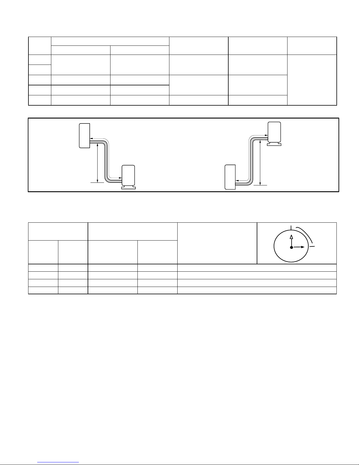
TABLE 9
REFRIGERANT LINE SET REQUIREMENTS, LENGTH AND HEIGHT LIMITATIONS AND OUTDOOR UNIT
REFRIGERANT METERING DEVICE TYPE (AIR CONDITIONER AND HEAT PUMP SYSTEMS)
System
Size
(kBtu)
Small Line Large Line
-09
1/4 in. (6 mm) 3/8 in. (9.5 mm) 33 feet (10 m) 66 Feet (20 m)
-12
-18 1/4 in. (6 mm) 1/2 in. (12 mm)
-24 1/4 in. (6 mm) 5/8 in. (16 mm)
-30 1/4 in. (6 mm) 5/8 in. 16 mm) 33 feet (10 m) 98 Feet (30 m)
Line Set Diameters
Maximum Line Set
Elevation
49 feet (15 m) 98 Feet (30 m)
Maximum Line Set
Length
Electronic Expansion
Note - Minimum line set length for all sizes is 10 feet (3 meters).
LINE SET LENGTH AND ELEVATION
Refrigerant
Metering Device
Type
Valve
INDOOR UNIT
Maximum Line
Set Elevation
Maximum Line Set Length
OUTDOOR UNIT
Maximum Line Set
Length
INDOOR UNIT
FIGURE 35
TABLE 10
TORQUE SPECIFICATIONS
Outside Diameter Recommended Torque
Inches
1/4” 6.35 15 ft.- lb. 20
3/8” 9.52 26 ft.- lb. 35 1/2 turn
1/2” 12.70 41 ft.- lb. 55 7/8 turn
5/8” 15.88 48 ft.- Ib. 65 1 full turn
mm U.S.
Metric (Newton
Meter)
No torque wrench available
Finger tighten and use an
appropriately sized wrench to turn an
additional:
1/4 turn
OUTDOOR UNIT
Maximum Line
Set Elevation
12
11
10
9
8
7
6
1
2
1/4 TURN
3
4
5
Page 21
Corp. 1244-L9
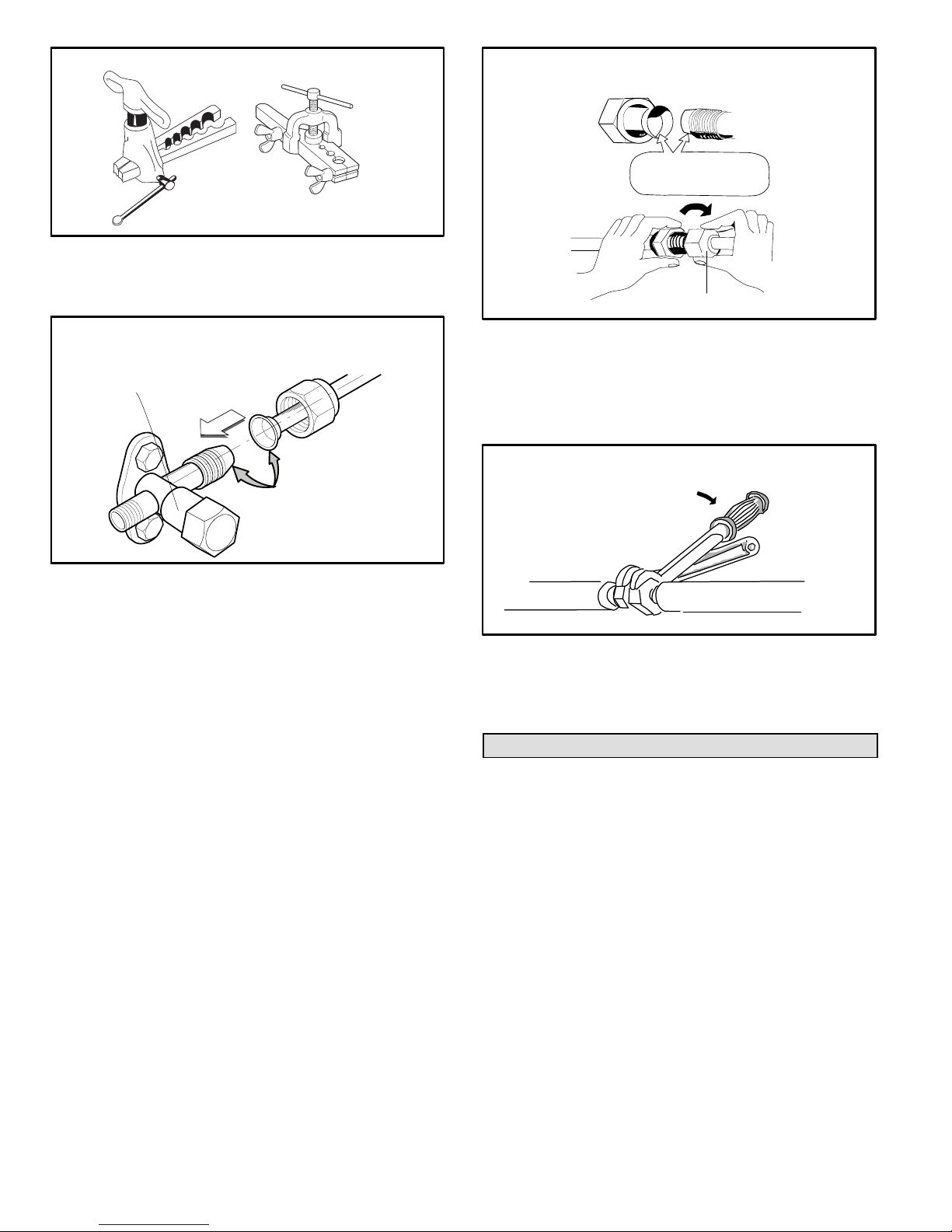
FLARING TOOLS
MAKING CONNECTIONS AT INDOOR UNIT
(MALE TO FEMALE CONNECTION)
A
APPLY REFRIGERANT
LUBRICANT HERE
CLUTCH TYPE
WING NUT TYPE
FIGURE 36
TYPICAL LINE SET CONNECTION TO
OUTDOOR UNIT
2-WAY LARGE LINE
SERVICE PORT
B
A
APPLY REFRIGERANT
LUBRICANT HERE
FIGURE 37
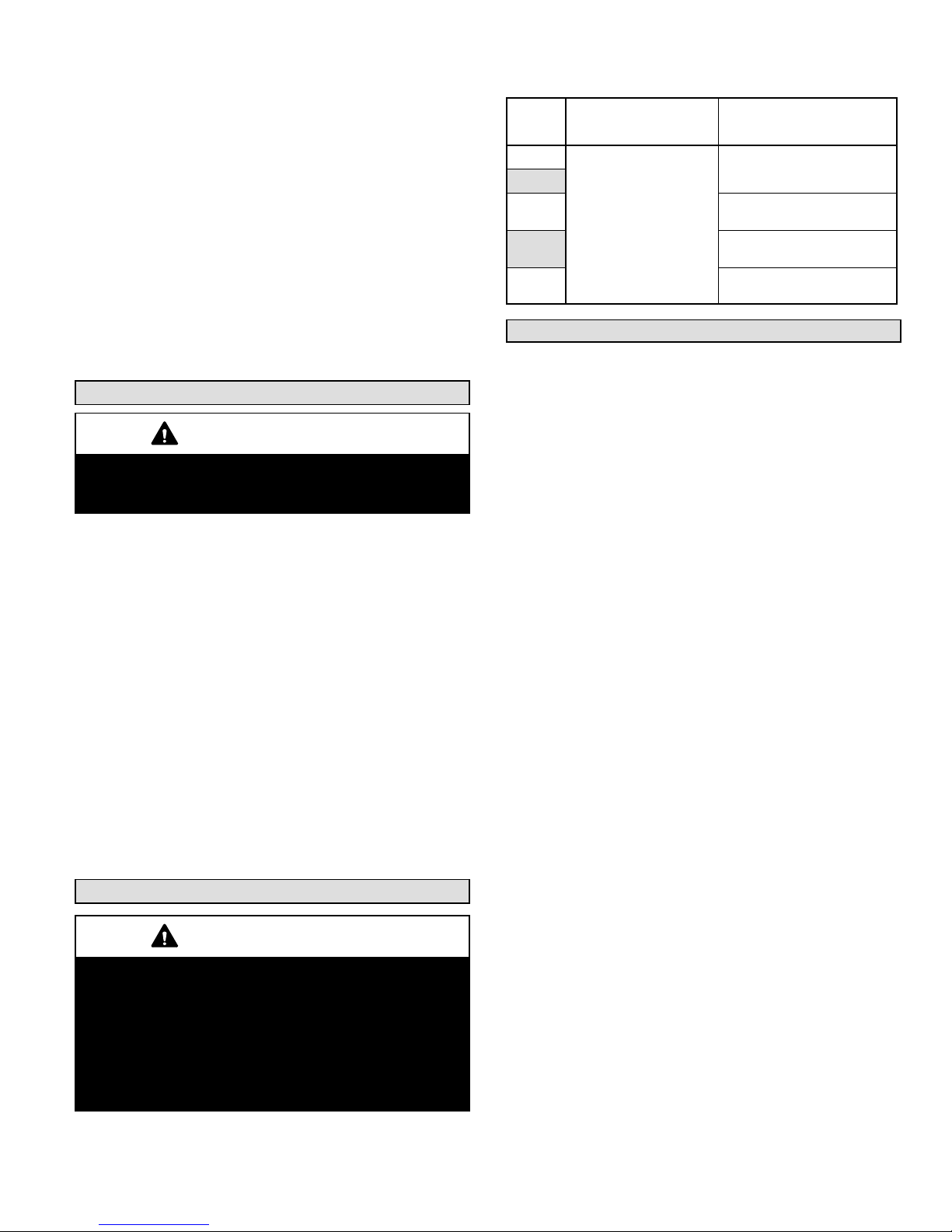
CONNECTING LINE SET TO OUTDOOR UNIT
1. Apply a sealing cap or water-proof tape to prevent dust
or water from getting into the refrigerant piping before
it is connected.
2. Apply refrigerant lubricant to the matching surfaces of
the flared line set and union before connecting them
together (figure 37 -- A). This will reduce refrigerant
leaks.
3. Align the flared refrigerant line with valve connection,
then tighten the flare nut lightly at first to obtain a
smooth match (figure 37 - B).
4. Tighten flare nuts. Do not over-tighten a flared joint.
Once snug, continue another half turn on each nut.
That should provide a gas-tight joint. You may also use
a torque wrench to tighten nuts using table 10
recommendations.
CONNECTING LINE SET BETWEEN INDOOR AND
OUTDOOR UNITS
1. Apply a sealing cap or water-proof tape to prevent dust
or water from getting into the refrigerant piping before
it is connected.
2. Apply refrigerant lubricant to the matching surfaces of
the flared line set and union before connecting them
together (figure 38 -- A).
3. Align the union tube and flared refrigerant line with
each other, then tighten the flare nut lightly at first to
obtain a smooth match (figure 38 -- B).
B
MALE FLARE CONNECTION
FIGURE 38
4. Tighten flare nuts. Do not over-tighten a flared joint.
Once snug, continue another half turn on each nut.
That should be a leak-free joint. You may also use a
torque wrench to tighten nuts using table 10
recommendations.
TIGHTEN FLARE NUT
TORQUE
WRENCH
TO INDOOR
UNIT
TO OUTDOOR UNIT
BACKUP
WRENCH
FIGURE 39
The line set between the indoor and outdoor unit must be
leak tested and evacuated to remove any noncondensables and moisture from the system.
Leak Test and Evacuation
Air and moisture remaining in the refrigerant system will
have undesirable effects as indicated below:
* Pressure in the system rises
* Operating current rises
* Cooling or heating efficiency drops
* Moisture in the refrigerant circuit may freeze and block
capillary tubing (-30 size only)
* Water may lead to corrosion of parts in the refrigeration
system
The line set between the indoor and outdoor unit must be
leak tested and evacuated to remove any noncondensables and moisture from the system.
LEAK TEST
1. Connect the manifold gauge set and dry nitrogen gas
cylinder to the large line service port as illustrated in
figure 40.
2. Pressurize the system to no more than 150 PSIG with
dry nitrogen. Check for leaks using soapy water.
3. After the system is found to be free of leaks, relieve the
nitrogen pressure by loosening the charge hose
MS8C / MS8H (208-230V)
Page 22
connector at the nitrogen cylinder. When the system
pressure is reduced to normal, disconnect the hose
from the cylinder.
EVACUATION
1. Connect the gauge set, micron gauge and vacuum
pump as shown in figure 40.
2. The operation time for evacuation varies with the line
set length and capacity of the pump. Allow the pump to
operate until the system has been evacuated down to
300 microns. Allow the pump to continue running for an
additional 15 minutes.
3. Turn off the pump and leave the connections secured
to the 3-way service valve. After five minutes, if the
system fails to hold 500 microns or less, check all
connections for tight fit and repeat the evacuation
procedure.
4. When the desired vacuum is reached, close the low
knob of the manifold valve and stop the vacuum pump.
Unit Start-Up
IMPORTANT
If unit is equipped with a crankcase heater, it should be
energized 24 hours before unit start-up to prevent
compressor damage as a result of slugging.
UNIT START-UP
1. Inspect all factory- and field-installed wiring for loose
connections.
2. Verify that the manifold gauge set is connected as
illustrated in figure 40.
3. Open the 3-way service and two-way shut off valves to
release the refrigerant charge contained in outdoor unit
into the system.
4. Replace the stem caps and tighten to the value listed
in table 5.
5. Check voltage supply at the outdoor unit terminal strip.
The voltage must be within the range listed on the unit's
nameplate. If not, do not start the equipment until you
have consulted with the power company and the
voltage condition has been corrected.
6. Refer to the included user guide to operate the system
using the provided remote control.
7. Visually check for binding of both indoor and outdoor
fans.
Adding Refrigerant for Longer Line Set
IMPORTANT
FV50S PVE is the ONLY acceptable oil for Lennox MS7
and MS8 mini-split systems.
Polyvinylether (PVE) is an innovative refrigerant oil
specially formulated for hydrofluorocarbon (HFC)
refrigeration systems. In addition to providing lubricating
properties, it also has a number of other applied
advantages that help to increase the reliability of the
refrigeration systems where it is applied.
1. Open the low side manifold gauge valve and weigh in
liquid refrigerant. Use table 12 to calculate the correct
weigh-in charge.
2. Close manifold gauge valves.
Table 11. Line Set Length and Adding Refrigerant
System
Size
(kBtu)
-09
-12
-18
-24
-30
Base Charge (outdoor
unit is sufficient for up
to listed length below)
26 feet (8 m)
Add Refrigerant
1 ounces per 40 inches (30
grams per meter)
0.71 ounces per 40 inches
(20 grams per meter)
1 ounces per 40 inches (30
grams per meter)
2 ounces per 40 inches (50
grams per meter)
Checking Large Line Operating Pressures
Connect gauge set to service port as illustrated in figure 40.
1. Indoor temperatures should be between 70F and 86F
(21C and 30C). Outdoor temperatures should be
between 23F to 118F (-5C to 48C).
2. Turn the remote control I FEEL function ON.
3. Set all indoor zone remote controls to lowest setting
61F {16C} in the Cool mode.
4. Turn ON the TURBO function. (Note: Allow 3 minutes
for compressor delay to time out).
5. Allow the system to operate for a minimum of 10
minutes before doing system checks: Indoor air coil
temperature drop (Range of 18 to 24F (10 to 13C).
Refrigerant pressure on big line. (Use pressure
ranges noted in table 12 for general guides. Minor
variations in these pressures may be expected due
to differences in installations).
HEATING
1. Indoor temperatures should be between 61F and 70F
(16C and 21C). Outdoor temperatures should be
between 5F to 80F (-15C to 27C)
2. Set all indoor zone remote controls to highest setting
86F {30C} in the Heat mode.
3. Turn the remote control I FEEL function ON.
4. Turn ON the TURBO function. (Note: Allow 3 minutes
for compressor delay to time out).
5. Allow the system to operate for a minimum of 10
minutes before doing system before checking:
Refrigerant pressure on big line. (Use pressure
ranges noted in table 12 for general guides. Minor
variations in these pressures may be expected due
to differences in installations).
IMPORTANT
If the operating pressures do not fall within the ranges given
in the pressure table:
A. Check the indoor or outdoor unit displays for error
code(s).
B. Refer to troubleshooting procedure diagrams in
Service and Installation manual to verify
component operation.
If no issues are found, follow the weigh-in charging
procedure below to charge the system.
Page 23
Corp. 1244-L9
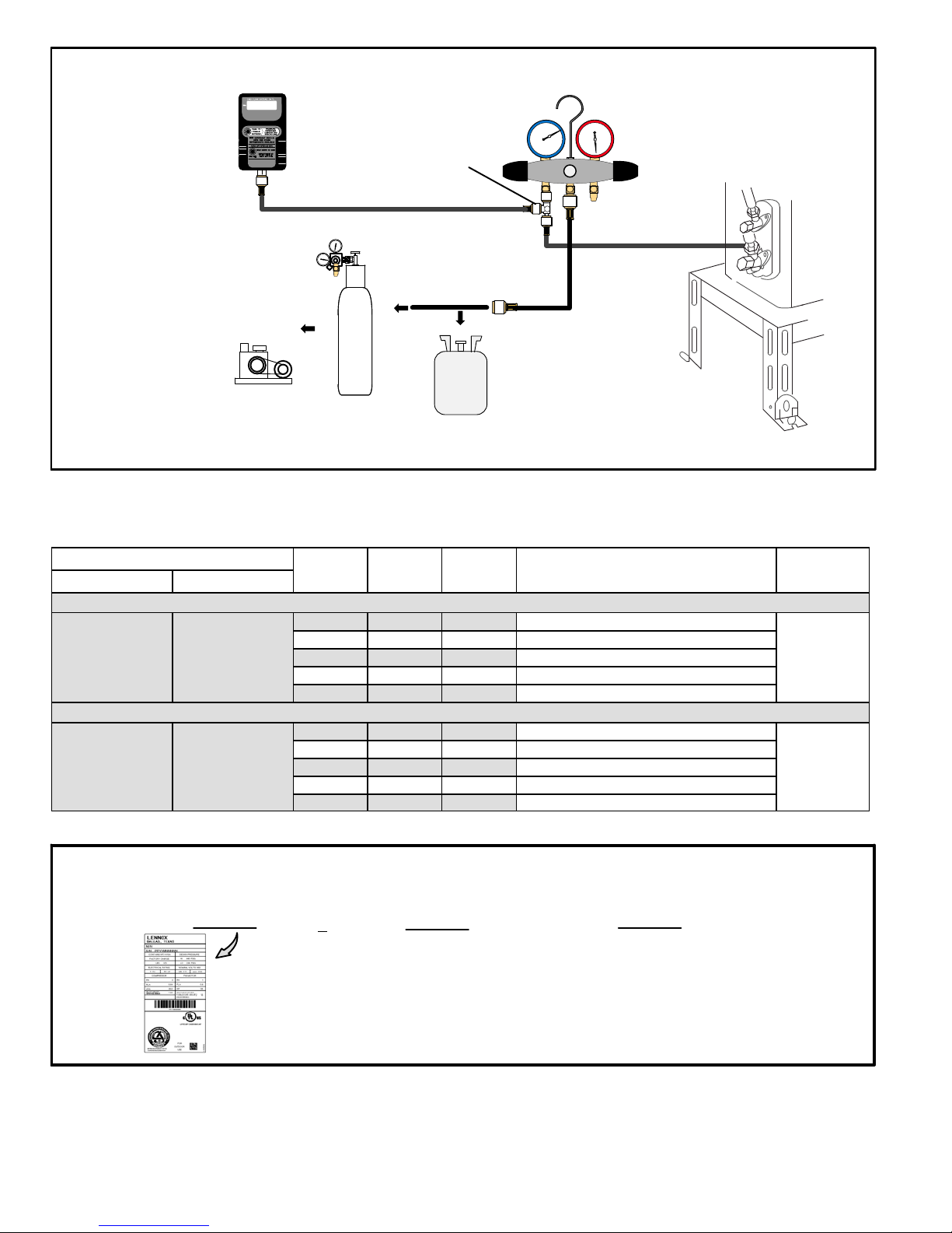
MANIFOLD GAUGE SET CONNECTIONS FOR LEAK TESTING, EVACUATION AND CHARGING
MICRON GAUGE
(REQUIRED FOR
EVACUATION
PROCEDURE ONLY)
VACUUM
PUMP
Temperature Condition ºF (ºC)
Indoor Outdoor
67 to 80
(19.4 to 26.7)
67 to 80
(19.4 to 26.7)
75 to 95
(23.9 to 35)
43 to 47
(6.1 to 8.3)
500
A34000 1/4 SAE TEE WITH
SWIVEL COUPLER
LOW
3
4
2
NITROGEN
HFC-410A
FIGURE 40
TABLE 12
LINE SET LENGTH AND ADDING REFRIGERANT
System
Size
(kBtu)
09K Turbo High 152 PSIG (1.05 MPa)
12K Turbo High 135 PSIG (0.93 MPa)
18K Turbo High 131 to 160 PSIG (0.9 to 1.1 MPa)
24K Turbo High 116 to 145 PSIG (0.8 to 1.0 MPa)
30k Turbo High 116 PSIG (0.8 MPa)
09K Turbo High 380 PSIG (2.62 MPa)
12K Turbo High 402 PSIG (2.77 MPa)
18K Turbo High 319 to 348 PSIG (2.2 to 2.4 MPa)
24K Turbo High 363 to 392 PSIG (2.5 to 2.7 MPa)
30K Turbo High 535 PSIG (3.69 MPa)
Indoor
Fan Mode
Cooling Mode
Heating Mode
Outdoor
Fan Mode
Standard Suction / Vapor Operating
HIGH
MANIFOLD GAUGE SET
Pressure Ranges
1
Line Set
Length
25 feet
(7.62 m)
25 feet
(7.62 m)
Note - Minimum line set length for all sizes is 10 feet (3 meters).
USING HFC-410A WEIGH-IN METHOD
Amount specified on
nameplate
Adjust amount. for variation in line set
length listed in table 12.
+
NOTE — The above nameplate is for illustration purposes only. Go to actual nameplate
on outdoor unit for charge information.
MS8C / MS8H (208-230V)
Total Charge
=
FIGURE 41
Page 24
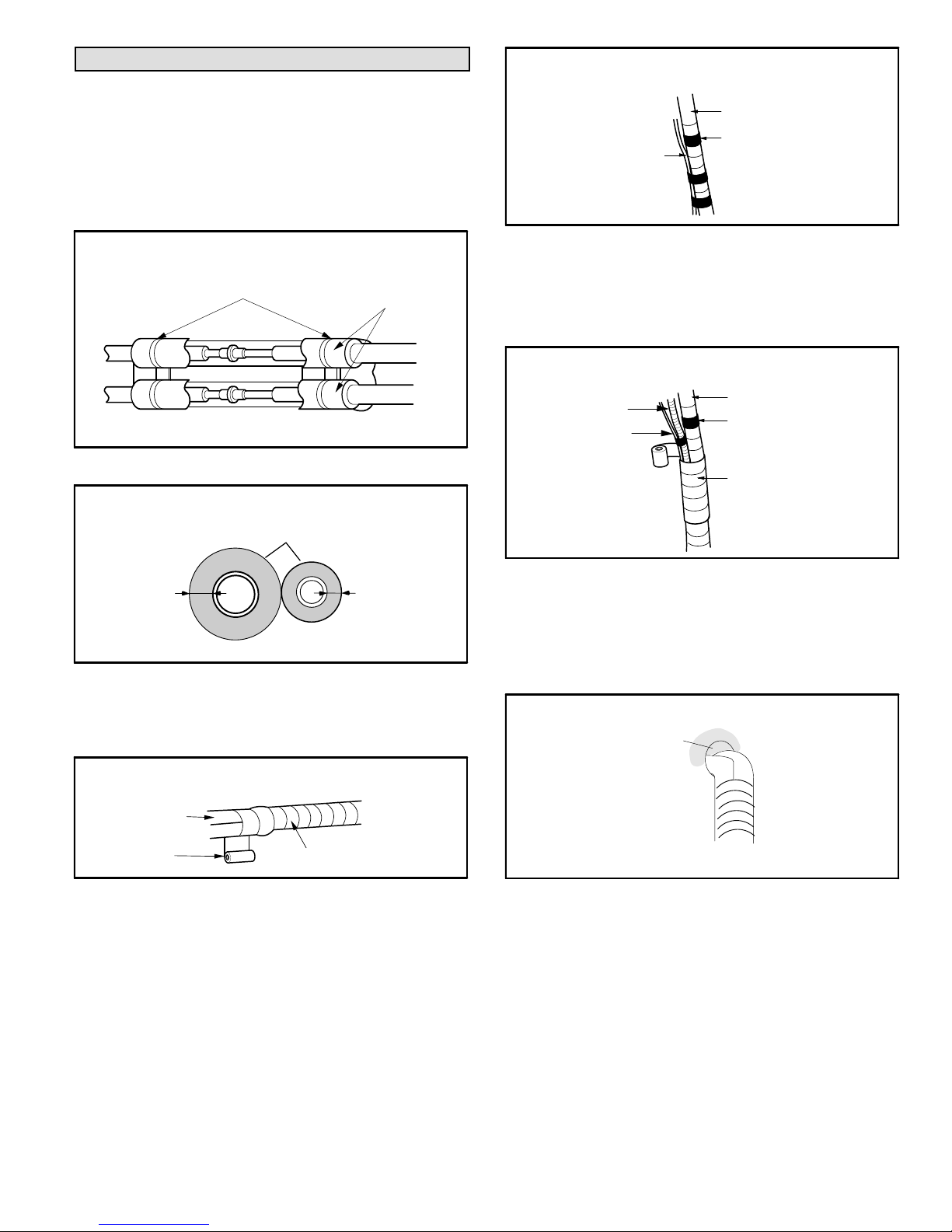
Wrapping Bundle
CONTROL WIRING BUNDLING
After system has been tested for leaks and proper
operation has been verified, use tape to bundle the control
wiring, line set and condensate line.
1. Wrap insulation material around the line set connection
between the indoor and outdoor units.
2. Insulate remaining sections of line set and condensate
line.
INSULATE AND TAPE LINE SET CONNECTION
PLASTIC WIRE TIES
TO INDOOR UNIT
INSULATION
MATERIAL
TO OUTDOOR UNIT
FIGURE 42
INSULATE LINE SET
INSULATION MATERIAL
INSULATE AND TAPE LINE
SET
CONTROL WIRING
BETWEEN INDOOR AND
OUTDOOR UNITS
WRAP WITH VINYL TAPE
(NARROW)
FIGURE 45
4. Tape the control wiring to the line set bundle (figure 45).
5. Start from the bottom of the bundle at the outdoor unit
and use tape to bundle the condensate line with the
control wiring and line set (figure 46).
UTILITY BUNDLE (CABLE, LINE SET AND
CONDENSATE DRAIN LINE)
CONDENSATE LINE
BETWEEN INDOOR
CABLE
AND OUTDOOR
UNITS
INSULATED LINE SET
WRAP WITH VINYL TAPE
(NARROW) (CABLE)
WRAP WITH VINYL TAPE
(WIDE)
MINIMUM
5/16” (8 MM)
LINE SET
MINIMUM
5/16” (8 MM)
FIGURE 43
3. Start from the bottom at the outdoor unit and use tape
to bundle the insulated line set together with tape
(figure 44).
TAPE LINE SET
LINE SET
WIDE VINYL
TAPE
WRAP WITH VINYL TAPE
FIGURE 44
FIGURE 46
1. Clamp bundle to wall. Use one clamp approximately
every 47” (1194 mm).
2. Apply sealant around the utility bundle on the outside
of the wall sleeve to prevent rain and outdoor air from
entering the room.
SEAL WALL SLEEVE AROUND BUNDLE
APPLY SEALANT HERE
BUNDLE
FIGURE 47
Page 25
Corp. 1244-L9
3. An optional field-provided exterior wall channel may be
used in lieu of taping the utility bundle (see figure 48)
to protect the bundle from UV rays, weather, etc.
OPTIONAL EXTERIOR WALL CHANNEL
FIELD-PROVIDED PROTECTIVE
CHANNEL (UTILITY BUNDLE
INSIDE)
FIGURE 48
Maintenance
OUTDOOR UNIT
1. Ensure power is off before cleaning.
2. It may be necessary to wash the outdoor coil more
frequently if it is exposed to substances which are
corrosive or which block airflow across the coil (e.g.,
pet urine, cottonwood seeds, fertilizers, fluids that may
contain high levels of corrosive chemicals such as
salts).
3. Outdoor Coil (Sea Coast) — Moist air in ocean
locations can carry salt, which is corrosive to most
metal. Units that are located near the ocean require
frequent inspections and maintenance. These
inspections will determine the need to wash the unit
including the outdoor coil. Consult your installing
contractor for proper intervals/procedures for your
geographic area or service contract.
4. Outdoor unit fan motor is pre-lubricated and sealed. No
further lubrication is needed.
5. Visually inspect all connecting lines, joints and coils for
evidence of oil leaks.
6. Check all wiring for loose connections.
7. Check for correct voltage at unit (unit operating).
INDOOR UNIT
1. Clean or change filters.
2. Check all wiring for loose connections
3. Check for correct voltage at unit (blower operating).
4. Clean coil, if necessary.
5. Check connecting lines and coils for signs of oil leaks.
6. Check condensate line and clean, if necessary.
NOTE
— The filter must be in place and the front panel must
be closed any time the unit is in operation.
MS8C / MS8H (208-230V)
Page 26
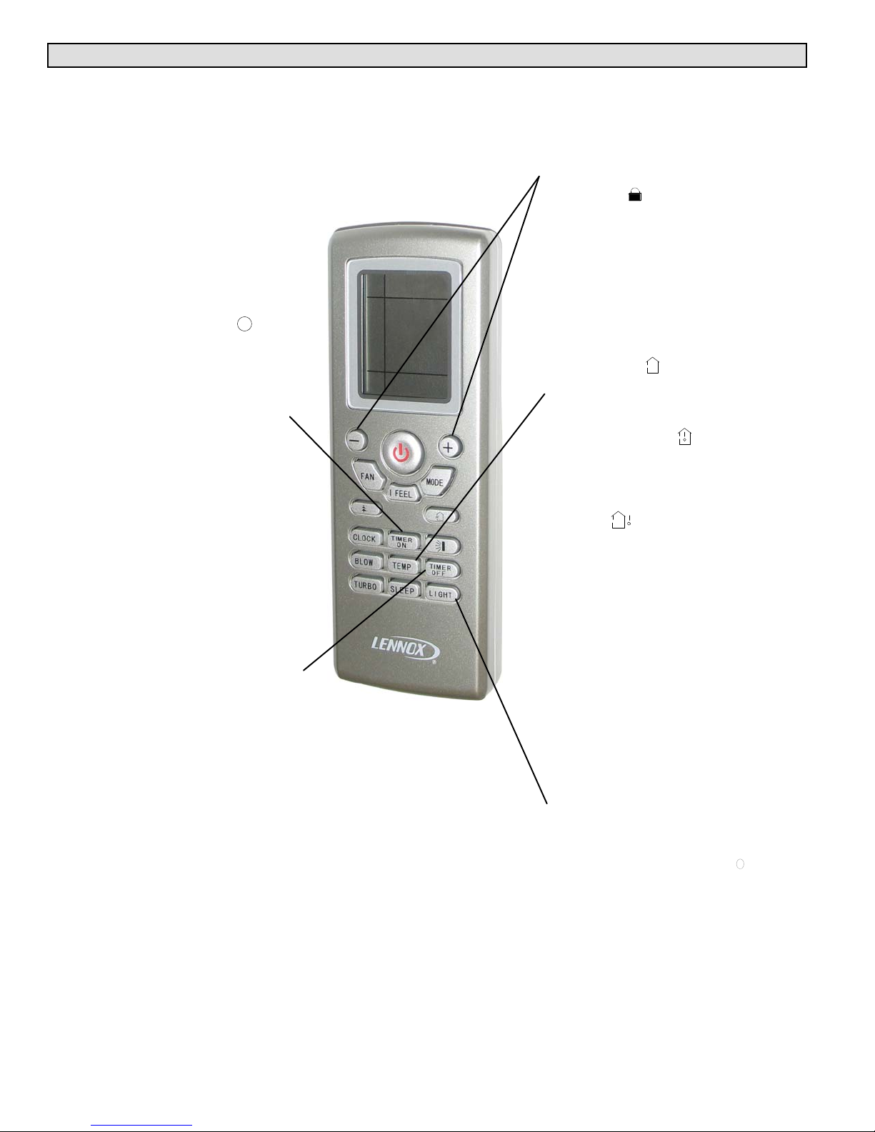
III. OPERATING THE WIRELESS REMOTE
Wireless Remote Functions
The wireless remote control provides system control to the homeowner at the touch of a
button. The indoor unit and remote control send information back and forth continuously.
The remote control must be placed on a table or other surface in direct line of sight with
the indoor unit infrared receiver. The remote control should not be placed in a drawer.
Make sure that there are no obstructions between the indoor unit receiver and the remote
control. Do not drop the control or spill liquid on the remote control.
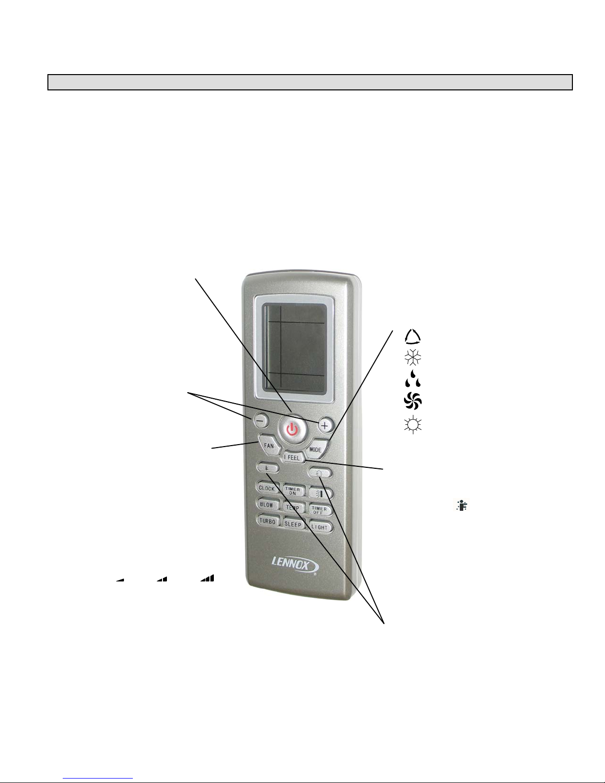
POWER button
Press this button once to turn
system on. Press again to
turn the system off. When the
POWER button is used to turn
the system OFF, it overrides the
Sleep Timer function (when it is
in use).
+/- buttons
Use plus (+) and minus (-) but
tons to adjust the temperature
setting up and down.
NOTE - The temperature cannot
be adjusted when the system is
in AUTO mode.
FAN button
Press this button to select fan
speed. AUTO fan is the default
setting. In AUTO fan mode, the
indoor fan speed is determined
by the indoor ambient tempera
ture. Press FAN button to step
through FAN setting selections:
AUTO, low speed, medium
speed and high speed.
Selected fan speed is shown at
the top of the remote control dis
play.
AUTO
Low Medium High
NOTE - The fan speed is not
adjustable during DEHUMIDIFI
CATION mode operation. The
low fan speed is necessary
to ensure optimal humidity
control.
MODE button
Press this button to select system
operating modes. AUTO mode is
the default setting. Press MODE
button again to select COOL mode,
again for DEHUMIDIFICATION
mode, again for FAN mode and
again for HEAT mode (heat pumps
only).
Selected mode is displayed on both
remote and indoor unit cover panel.
AUTO
COOL
DEHUMIDIFICATION
FAN
HEAT
I FEEL button
Press the I FEEL button to acti
vate the I FEEL feature. When
the I FEEL icon appears, tem
perature sensor in remote control
is used to initiate heating or cool
ing demands. Press
I FEEL button again to cancel
I FEEL feature and transfer room
temperature sensing back to
sensor in indoor unit.
UNUSED buttons
These buttons are not
functional in the MS8
system.
Page 27
Corp. 1244-L9
Wireless Remote Functions (Continued)
SWITCH FROM °C TO °F
With system OFF, press MODE
and - buttons simultaneously to
switch from Centigrade to
Fahrenheit. Current selection
is displayed to the right of the
temperature display.
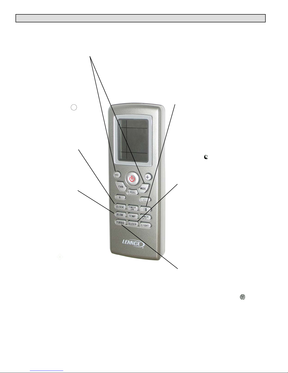
CLOCK button
Use the CLOCK button to adjust
the time displayed on the remote
control. Press the CLOCK button
once. The clock icon will
flash. Within 2 seconds, use the and + buttons to adjust the time
down or up in one-minute incre
ments. Press the button continu
ously to adjust the time in
10-minute increments. Press the
CLOCK button again when cor
rect time is displayed.
BLOW button
Use the BLOW button to
extend low speed blower
operation for 10 minutes
at the end of a cooling
demand.
The extended fan (BLOW)
operation ensures that excess
moisture is removed from the
indoor coil before the blower
shuts off.
Press the BLOW button once to
initiate extended blower opera
tion. Fan operation ends after 10
minutes.
The extended fan (BLOW)
operation icon is displayed
when the feature is turned on.
Extended fan (BLOW) operation
is available in cooling or dehu
midification modes; extended fan
(BLOW) operation is not avail
able in AUTO, heating or fan
mode.
LOUVER SETTING button
See page for complete details on
louver operation.
SLEEP button
Use the SLEEP button to initiate
or cancel the sleep function.
Press SLEEP button. When
sleep icon appears, press
TIMER OFF button and use and + buttons to set time for sys
tem shutdown. When desired
time is displayed, press TIMER
OFF button again. Press SLEEP
button to cancel sleep function.
In cooling mode, SLEEP function
increases temperature (+1.8°F
per hour) over a two-hour period
after the selected sleep time.
In heating mode, SLEEP function
decreases temperature (-1.8°F
per hour) over a two-hour period
after the selected sleep time.
NOTE - The sleep function is not
available in AUTO or FAN
modes.
TURBO button
Use the TURBO button to
initiate or cancel high-speed fan
operation to accelerate cooling
or heating of the ambient room
temperature. The turbo icon
is displayed when the function is
turned on.
MS8C / MS8H (208-230V)
Page 28
Wireless Remote Functions (Continued)
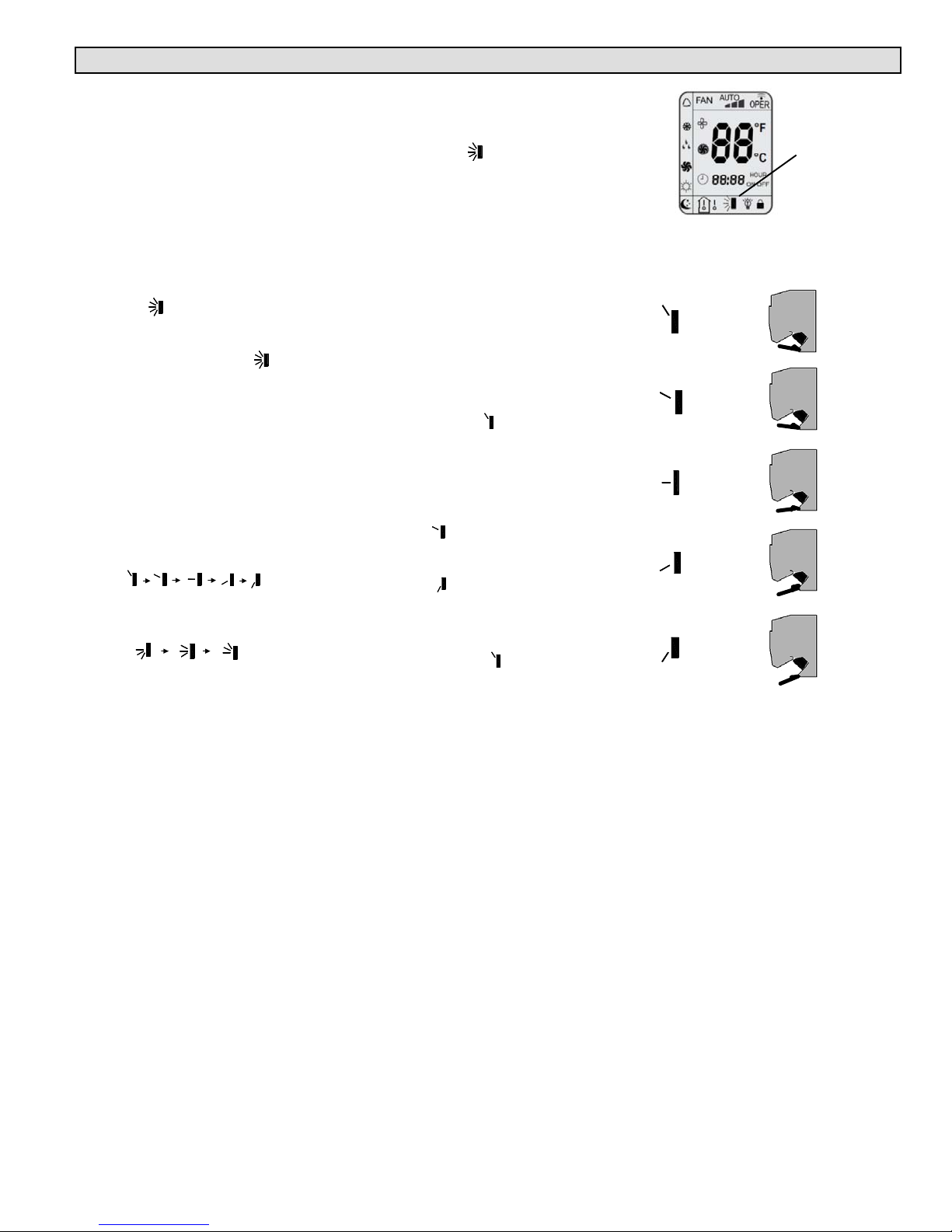
LOUVER SETTING button
Use the LOUVER SETTING
button to choose a preferred
setting for the indoor unit
directional louver.
NOTE - Actual louver
position is different than
what is shown on remote
icon. See comparison to
the right.
Press the LOUVER SETTING
button once to activate the
full-range oscillation mode
from top to bottom, then back
again. The louver icon will
appear in the lower section of
the screen.
Press the LOUVER SETTING
button again to turn the
feature OFF. The louver will
return to the default setting.
Press the LOUVER SETTING
button twice and continue to
press the button to scroll
through the five available
fixed positions
AND three other oscillating
positions.
To return the louver to the
default position, press the
LOUVER SETTING button
until the icon disappears.
Default Louver Positions
When the louver setting icon
is not displayed, the louver is
in the DEFAULT position.
When the remote control is
powered OFF, the default
position is fully closed.
When the remote control is set
so that the unit is in
COOLING, AUTO COOLING,
or DEHUMIDIFICATION
mode, the louver is in a fixed
upward position .
When the remote control is set
so that the unit is in HEAT or
AUTO HEATING mode and
the outdoor unit is OFF, the
louver is fixed in the second
position pointed upward. If
the outdoor unit is ON, the
louver is fixed in a downward
position .
When the remote is set for
continuous indoor fan to be
ON, the louver is fixed in an
upward position .
REMOTE
CONTROL ICON
POSITION
LOUVER
SETTING
ACTUAL
LOUVER
POSITION
o r a b o v e
ICON
Page 29
Corp. 1244-L9
Wireless Remote Functions (Continued)
TIMER ON button
Use the TIMER ON button to ini
tiate or cancel a single timed-on
event. Use this feature to bring
the system on just before you re
turn home or just before you
wake in the morning.
Press the TIMER ON button
once. The clock icon
disappears and a time setting ap
pears with the word ON flashing
at the right. Use the - and + keys
to adjust the time setting to the
desired time for the system to
begin operation. Press the TIM
ER ON button again to
accept the setting. When suc
cessfully set, the word ON will
appear to the right of the current
time display. Press the TIMER
ON button again if you want to
cancel the timed-on event.
TIMER OFF button
Use the TIMER OFF button to
initiate or cancel a single timedoff event. Use this feature to turn
the system off just after you
leave the house or just after you
go to bed at night.
Use the same method
described above to set the de
sired time for the system to stop
operation. When successfully
set, the word OFF will appear to
the right of the current time dis
play. Press the TIMER OFF but
ton again if you want to cancel
the timed-off event.
REMOTE LOCK
Press - and + buttons simulta
neously to either lock or unlock
the remote control buttons. When
locked, the icon is
displayed.
TEMP button
Use the TEMP button to change
the temperature display shown
on the remote control. When ini
tially powered on, the current
temperature setting is displayed,
along with the icon.
Press the TEMP button once
to alter the display to show the
current indoor ambient tempera
ture, along with the icon. The
indoor temperature sensor is in
the indoor unit.
Press the TEMP button again to
display the outdoor ambient tem
perature icon. The outdoor
ambient temperature display is
not available on this system.
On occasion, the remote control
will display the temperature that
was not selected (indoor ambient
temperature or setting tempera
ture). The selected temperature
will return to the display screen
after 5 seconds.
NOTE - The TEMP button can
also be used to temporarily dis
play the indoor ambient tempera
ture on the indoor unit display
panel.
LIGHT button
Use the LIGHT button to turn the
indoor unit display light on and
off. When the light is on, the
icon appears on the remote con
trol.
MS8C / MS8H (208-230V)
Page 30
 Loading...