

Page 1
INSTALLATION AND SERVICE
MS8 SERIES
Corp. 1244-L9
Revised January 12, 2015
PROCEDURES
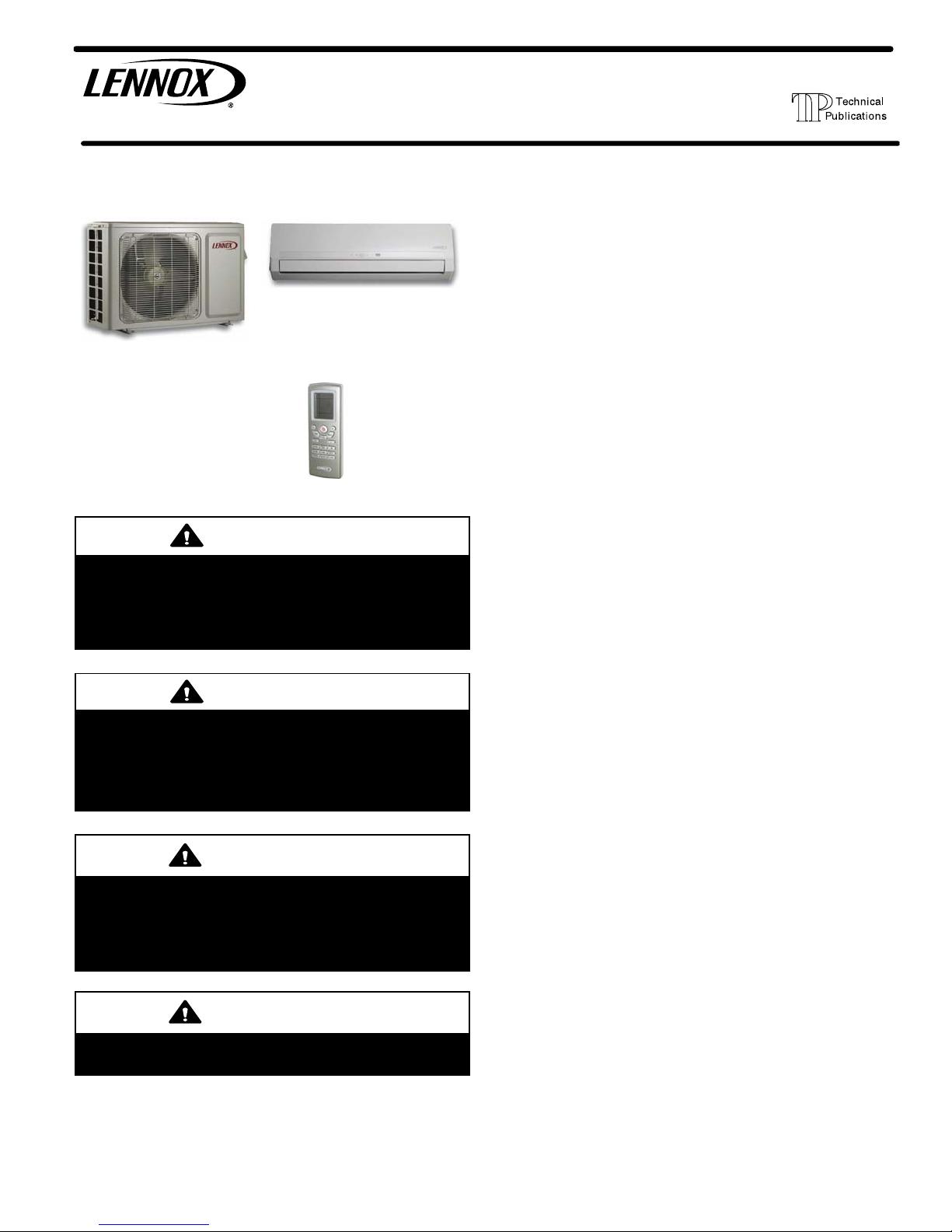
MS8 SERIES UNITS — MINI-SPLIT SINGLE-ZONE SYSTEMS (208-230V)
TABLE OF CONTENTS
I. OVERVIEW
Shipping and Packing List 2......................
MS8-CI Air Conditioner Indoor Unit
MS8-HI Heat Pump Indoor Unit
MS8-CO Air Conditioner Outdoor Unit
MS8-HO Heat Pump Outdoor Unit
Wireless
Remote Control
(furnished)
CAUTION
Physical contact with metal edges and corners while
applying excessive force or rapid motion can result in
personal injury. Be aware of, and use caution when
working near these areas during installation or while
servicing this equipment.
WARNING
Improper installation, adjustment, alteration, service or
maintenance can cause personal injury, loss of life, or
damage to property.
Installation and service must be performed by a licensed
professional installer (or equivalent) or a service agency.
IMPORTANT
The Clean Air Act of 1990 bans the intentional venting of
refrigerant (CFCs, HCFCs and HFCs) as of July 1, 1992.
Approved methods of recovery, recycling or reclaiming
must be followed. Fines and/or incarceration may be
levied for noncompliance.
IMPORTANT
These units must be installed as a matched system as
specified in the Lennox Engineering Handbook.
Required Tools and Supplies 3....................
Specifications 4.................................
Model Number Identification 6....................
Unit Dimensions and Weights 6...................
Typical System Component Setup 6...............
II. INSTALLATION
General 8......................................
Clearances 8...................................
Torque Requirements for Caps and Fasteners 8....
Setting Outdoor Unit 8...........................
Repositioning Indoor Air Temperature Sensor 10.....
Indoor Unit Placement and Preparation 10..........
Indoor Unit Cable Connections 14..................
Securing Indoor Unit to Wall Mounting Bracket 15....
Outdoor Unit Cable Connections 16................
Operating Service Valves 19.......................
Line Set Requirements 20.........................
Leak Test and Evacuation 22......................
Unit Start-Up 23.................................
Adding Refrigerant for Longer Line Sets 23..........
Checking Large Line Operating Pressures 23........
Wrapping Bundle 25..............................
Maintenance 26....................................
III. OPERATING THE WIRELESS REMOTE
IV. SYSTEM OPERATION AND SERVICE
System Operational Modes 35.......................
System Functions 43...............................
System Protection Features 44......................
Other Functions 46.................................
Temperature Sensors (location, function and
troubleshooting 47.................................
Indoor and Outdoor Control Parts Identifications 53.....
Indoor and Outdoor Error Codes 57..................
Refrigerant System Flow Diagrams 66................
Typical Unit Wiring Diagrams 67...................
Troubleshooting 72.................................
Major System Components 81.......................
Optional Condensate Pump Wiring Connection 88...........
Disassembly Procedures 88.........................
Page 1
2015 Lennox Industries Inc.
Page 2
I. OVERVIEW
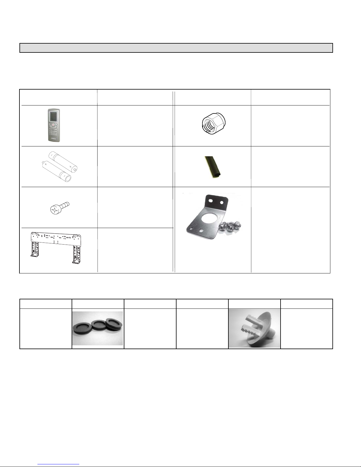
Shipping and Packing List
Check the unit components for shipping damage. If you find any damage, immediately contact the last carrier.
1 — ASSEMBLED INDOOR UNIT
The assembled indoor unit will include the following items:
Part Picture
Part Name
Remote control (1 each)
Batteries (AAA)
(2 each)
Wall mounting bracket
screws (5 each)
Wall mounting bracket
(1 each)
Part Picture
Name Name
1/4” flare nut (45º-degree
SAE style) for small line
(1 each)
Foam tube insulation
(for condensate line at
tached to indoor unit)
Cable routing guide with
mounting hardware (in
cluded with 18, 24 and
30kBtu. The -09 and 12
kBtu sizes include factory
installed cable routing
guide.
1 — ASSEMBLED OUTDOOR UNIT
The assembled outdoor unit will include the following items which are located with the unit:
Parts
Auxiliary drain
hole plugs (heat
pump only)
MS8C / MS8H (208-230V)
Figure Quantity Parts Figure Quantity
1 - 3
Drain plug
(heat pump only)
Page 2
1
Page 3
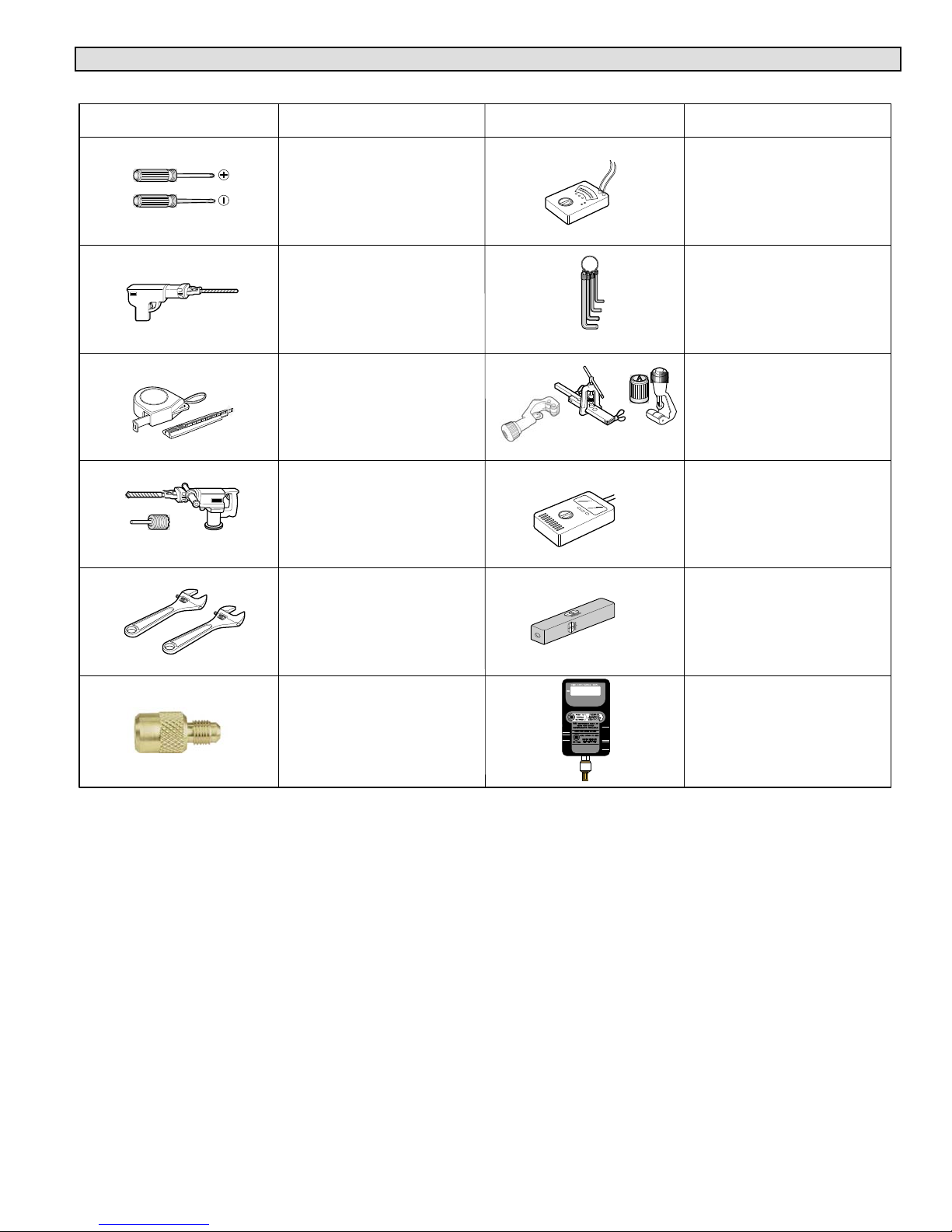
Required Tools and Supplies
INSTALLATION TOOLS
Tool Picture
Tool Name
Screw driver
Electric drill
Measuring tape and
knife
Hole core drill
Tool Picture
Tool Name
Multimeter
Allen wrench set
(metric)
Flaring tool and pipe
cutter
Refrigerant leak detector
or a bottle of soapy water
Adjustable wrench
500
Level
A 5/16” female flare to
1/4” male flare adapter
(order Lennox catalog
Micron gauge
number Y0576)
SUPPLIES
The following field-provided supplies may be required for installation
* Line set (see table 9 for requirements)
* Foam insulation (line set and condensate line)
* UV rated protective tape (used to maintain positioning of bundle). Bundle consists of line set, condensate line and wiring
between indoor and outdoor units.
* UV rated cable ties
* Outdoor unit pad
* Outdoor disconnect switch (indoor unit disconnect switch may be required by local code)
* Cable (4-conductor). All need to be rated either 208-240V and sized per NEC).
NOTE — Stranded wire must be used to connect the outdoor unit to the indoor unit. The stranded wire is necessary to ensure
proper system communication and operation.
* Plastic wall screw anchors
* Exterior wall channel (optional)
* Wall sleeve or PVC tubing material to field fabricate a wall sleeve for line set, condensate line and wiring (utility bundle).
Page 3
Corp. 1244-L9
Page 4
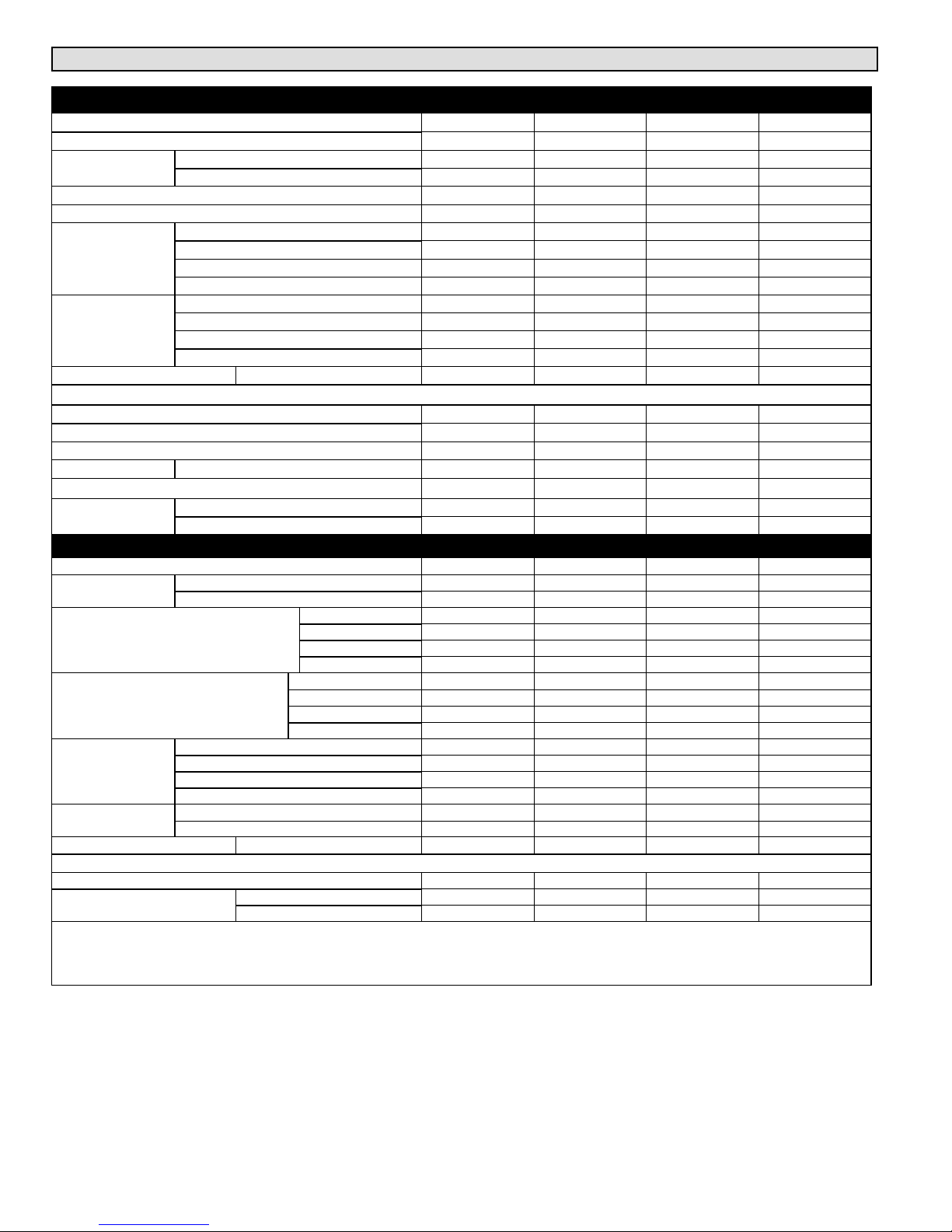
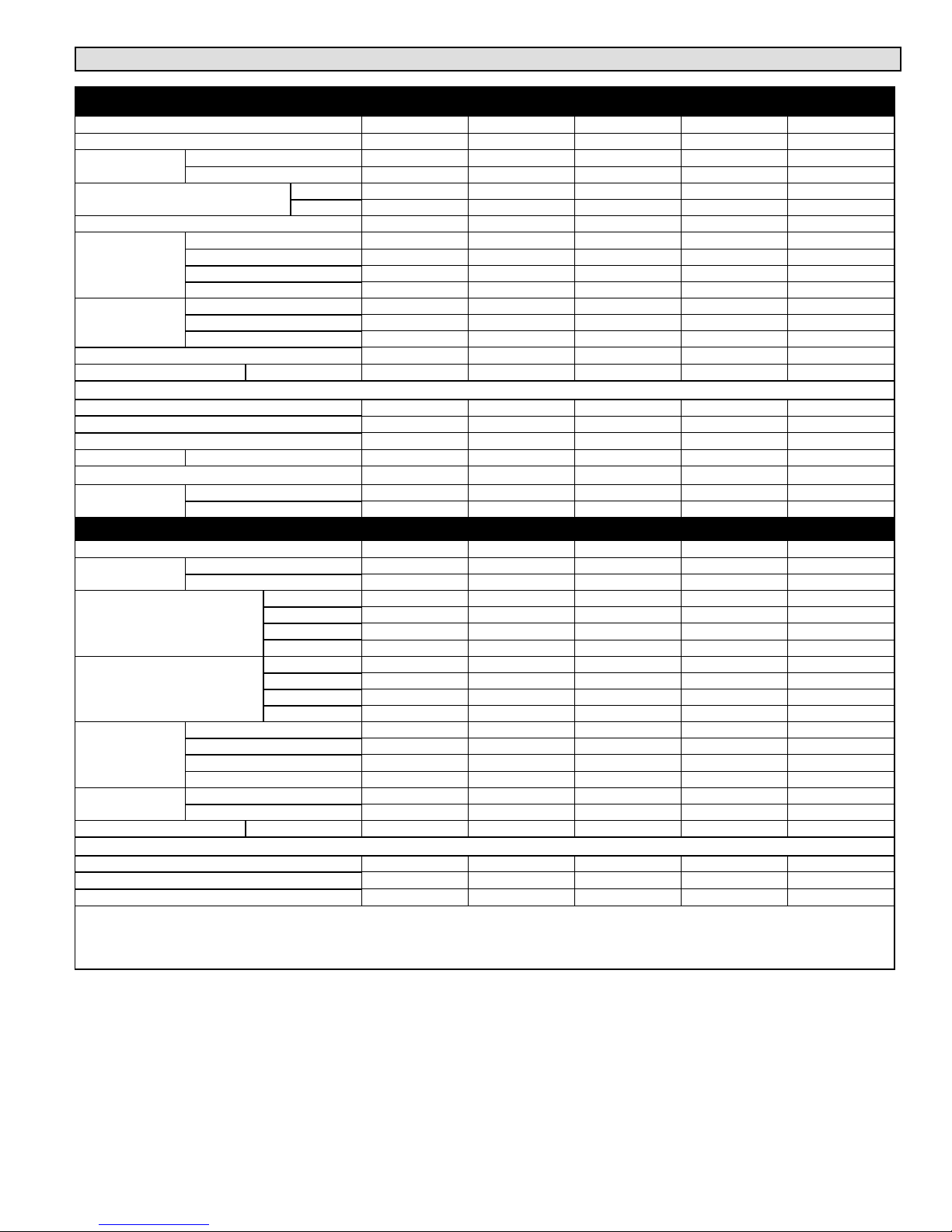
Specifications - AIR CONDITIONER SYSTEMS
OUTDOOR UNIT
Nominal Tonnage 0.75 1 1.5 2
Outdoor Unit Model No. MS8CO09P MS8CO12P MS8CO18P MS8CO24P
Connections (in.)
Ambient Temperature Operating Range °F 0 109 0 109 5 109 5 109
1
Refrigerant (R410A) furnished 2 lbs. 14 oz. 2 lbs. 14 oz. 3 lbs. 1 oz. 3 lbs. 9 oz.
Outdoor Coil
Outdoor Fan
Motor
Shipping Data lbs. Outdoor Unit 91 97 110 132
ELECTRICAL DATA
2
Maximum overcurrent protection (amps) 15 15 20 25
Compressor Rated load amps 27.2 6.5 9.7 11
4
Compressor Power Input (W)
Outdoor Fan
Motor
Connections (in.)
Indoor Blower Air Volume (cfm)
Indoor Blower RPM
Indoor Coil
Indoor Blower
Shipping Data lbs. Indoor Unit 31 29 38 47
Line voltage data 60 hz 1ph 208/230V 208/230V 208/230V 208/230V
ELECTRICAL DATA
Line voltage data 60 hz 1ph 208/230V 208/230V 208/230V 208/230V
NOTE Extremes of operating range are plus 10% and minus 5% of line voltage.
1
Refrigerant charge sufficient for 15 ft. of line set.
2
HACR type circuit breaker or fuse.
3
Refer to National or Canadian Electrical Code manual to determine wire, fuse and disconnect size requirements.
4
Rated Input
Small line o.d. flare 1/4 1/4 1/4 1/4
Large line o.d. flare 3/8 3/8 1/2 5/8
Net face area sq. ft. 4.08 4.49 5.96 7.66
Tube diameter in. 1/4 3/8 1/4 1/4
Number of rows 2 2 2 2
Fins per inch 20 20 20 20
Diameter in. 153/4 153/4 201/2 213/4
No. of blades 3 3 3 3
Cfm 940 940 1885 2355
Rpm 680/900 680/900 800 800
3
Minimum circuit ampacity 10 10 13 16
1075 860 1200 1420
Rated load amps 0.13 0.13 0.28 1.1
Output (W) 40 30 60 90
MATCHING INDOOR UNIT
Indoor Unit Model No. MS8CI09P MS8CI12P MS8CI18P MS8CI24P
Small line o.d. flare 1/4 1/4 1/4 1/4
Large line o.d. flare 3/8 3/8 1/2 5/8
Turbo 305 335 500 590
High 275 275 460 470
Medium 255 255 385 410
Low 220 220 325 355
Turbo 1260 1330 1500 1500
High 1100 1100 1200 1200
Medium 950 950 1050 1050
Low 750 750 900 900
Net face area sq. ft. 1.65 1.65 2.33 3.23
Tube diameter in. 1/4 1/4 1/4 1/4
Number of rows 2 2 2 2
Fins per inch 20 20 20 18
Diameter x Length in. 3.6 x 25.4 3.6 x 25.4 3.9 x 28 3.9 x 30
Type Crossflow Crossflow Crossflow Crossflow
Rated Load Amps 0.20 0.20 0.32 0.24
Output (W) 20 20 20 60
MS8C / MS8H (208-230V)
Page 4
Page 5
Specifications - HEAT PUMP SYSTEMS
OUTDOOR UNIT
Nominal Tonnage 0.75 1 1.5 2 2.5
Outdoor Unit Model No. MS8HO09P MS8HO12P MS8HO18P MS8HO24P MS8HO30P
Connections
(in.)
Ambient Temperature Operating
Range °F
1
Refrigerant (R410A) furnished 2 lbs. 14 oz. 2 lbs. 14 oz. 3 lbs. 1 oz. 3 lbs. 9 oz. 5 lbs. 5 oz.
Outdoor Coil
Outdoor Fan
Motor
Shipping Data lbs. Outdoor Unit 11 0 119 110 135 164
ELECTRICAL DATA
Line voltage data 60 hz 1ph 208/230V 208/230V 208/230V 208/230V 208/230V
2
Max. overcurrent protection (amps) 15 15 20 25 30
Compressor Rated load amps 7.2 6.5 9.7 11 13.5
4
Compressor Power Input (W)
Outdoor Fan
Motor
Connections
(in.)
Indoor Blower Air Volume
(cfm)
Indoor Blower RPM (Cooling/
Heating)
Indoor Coil
Indoor Blower
Shipping Data lbs. Indoor Unit 37 37 38 47 60
ELECTRICAL DATA
Line voltage data 60 hz 1ph 208/230V 208/230V 208/230V 208/230V 208/230V
NOTE Extremes of operating range are plus 10% and minus 5% of line voltage.
1
Refrigerant charge sufficient for 15 ft. of line set.
2
HACR type circuit breaker or fuse.
3
Refer to National or Canadian Electrical Code manual to determine wire, fuse and disconnect size requirements.
4
Rated Input
Small line o.d. flare 1/4 1/4 1/4 1/4 1/4
Large line o.d. flare 3/8 3/8 1/2 5/8 5/8
Cooling 0 109 0 109 14 109 14 109 5 109
Heating –5 75 –5 75 19 75 19 75 17 75
Net face area sq. ft. 4.08 4.49 5.96 7.66 7.66
Tube diameter in. 1/4 3/8 1/4 1/4 5/16
Number of rows 2 2 2 2 2
Fins per inch 20 20 20 20 18
Diameter in. 153/4 153/4 201/2 213/4 213/4
No. of blades 3 3 3 3 3
Cfm 940 940 1885 2355 2355
Rpm 680/900 680/900 800 800 830
3
Minimum circuit ampacity 10 10 13 16 20
860 860 1200 1420 2450
Rated load amps 0.13 0.13 0.28 1.1 0.45
Output (W) 30 30 60 90 90
MATCHING INDOOR UNIT
Indoor Unit Model No. MS8HI09P MS8HI12P MS8HI18P MS8HI24P MS8HI30P
Small line o.d. flare 1/4 1/4 1/4 1/4 1/4
Large line o.d. flare 3/8 3/8 1/2 5/8 5/8
Turbo 306 335 500 590
High 277 277 459 470 705
Medium 253 253 383 410 675
Low 218 218 324 355 645
Turbo 1260/1320 1330/1350 1500/1500 1500/1450
High 1100/1200 1100/1170 1200/1250 1200/1150 1410/1410
Medium 950/1100 950/1050 1050/1150 1050/1020 1280/1280
Low 750/950 750/950 900/1050 900/950 1200/1200
Net face area sq. ft. 1.65 1.65 2.33 3.23 14.8
Tube diameter in. 1/4 1/4 1/4 1/4 1/4
Number of rows 2 2 2 2 2
Fins per inch 20 20 20 18 18
Diameter x Length in. 3.6 x 25.4 3.6 x 25.4 3.9 x 28 3.9 x 30 4.25 x 20.5
Type Crossflow Crossflow Crossflow Crossflow Crossflow
Rated Load Amps 0.20 0.20 0.32 0.24 0.40
Output (W) 20 20 20 60 40
Page 5
Corp. 1244-L9
Page 6
Model Number Identification
−
8
Series Type
MS = Mini-Split
Series
Unit Type
CI = Air Conditioner Indoor Unit
HI = Heat Pump Indoor Unit
CO = Air Conditioner Outdoor Unit
HO = Heat Pump Outdoor Unit
CIMS
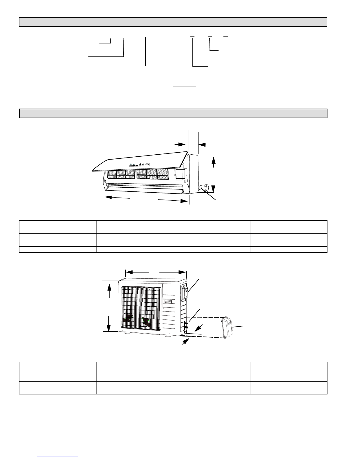
Unit Dimensions - inches (mm) and Weights
INDOOR UNIT
A
TABLE 1. INDOOR UNIT DIMENSIONS — INCHES
Model Size A B C
-09 and -12 33-3/8 10-7/8 7
-18 37 11-3/4 8
-24 39-3/4 12-3/8 8-5/8
-30 53-1/8 12-7/8 10
−09
P
1 A
Minor Revision
Number of Zones
1 = single zone
Voltage
L = 115V-1phase-60hz
Capacity - BTUH
09 = 9,000
12 = 12,000
C
C
B
LINE SET, CONDENSATE
DRAIN AND ELECTRICAL
CONNECTIONS
Model Size A B C
-09 21-1/4 30 12-5/8
-12 23-1/4 30 12-5/8
-18 27-5/8 35 15-5/8
-24 and -30 31-1/8 36 16-7/8
MS8C / MS8H (208-230V)
B
ELECTRICAL CONNECTIONS (UNDER COVER)
A
LINE SET CONNECTIONS
(COVER REMOVED)
C
TABLE 2. OUTDOOR UNIT DIMENSIONS — INCHES
Page 6
LINE SET COVER
Page 7
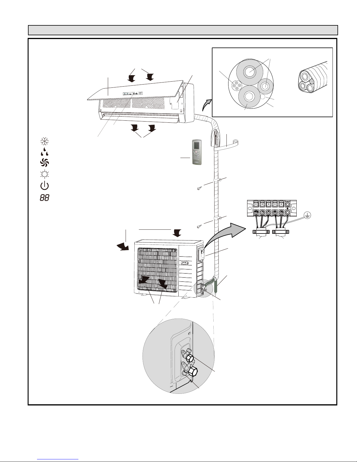
TABLE 3. OUTDOOR UNIT DIMENSIONS — INCHES (MILLIMETERS)
Typical System Component Setup
TYPICAL COMPONENT SETUP
RETURN AIR
B
INDOOR UNIT
DISPLAY
D
INDICATORS
COOL
DRY
FAN
HEAT
RUN
TEMPERATURE SETTING,
INDOOR AMBIENT TEMPERATURE
OR ERROR CODE
NOTE — temperature can be
displayed in either Fahrenheit or
Celsius.
D
C
SUPPLY AIR
AIR IN
A
WIRELESS REMOTE
CONTROL
OUTDOOR UNIT (AIR
CONDITIONER OR HEAT
PUMP)
E
G
K
L
TAPE
H
REFRIGERANT LINE SET, CONDENSATE LINE
F
AND INDOOR / OUTDOOR CABLE
IMPORTANT - The refrigerant
metering device for this system is
located in the outdoor unit. This
makes it necessary to insulate
the refrigerant lines individually to
prevent sweating.
OUTDOOR UNIT
TERMINAL BLOCK
A. Remote control
B. Front panel
C. Filters
D. Guide louver with display
E. Line set (wrapped in foam insulation)
F. UV-rated tape (field-provided)
G. Wiring (field-provided)
H. Condensate drain line (field-provided)
(wrapped in foam insulation). Recommend
installation of a vent when making long
horizontal runs on condensate line.
I. 3-way service valve
J. Access cover for power and control wiring
connections
K. Indoor unit wiring connections (under
access plate)
AIR OUT
FIGURE 1
J
H
I
2-WAY SHUT-OFF VALVE
3-WAY SERVICE VALVE
(FLARE CONNECTION)
TO INDOOR
UNIT
TO POWER
SUPPLY
Page 7
Corp. 1244-L9
Page 8
II. INSTALLATION
IMPORTANT INSTALLER INFORMATION
* Confirm proper slope and routing of condensate lines to ensure moisture is drained away from the indoor unit (see
procedure starting on page 12)
* Confirm proper insulating, taping and bundling of refrigeration lines, main power lines and drain line (see procedure
starting on pages 25).
General
The MS8 air conditioners and heat pumps are matched with
an indoor evaporator unit to create a ductless system that
uses HFC-410A refrigerant.
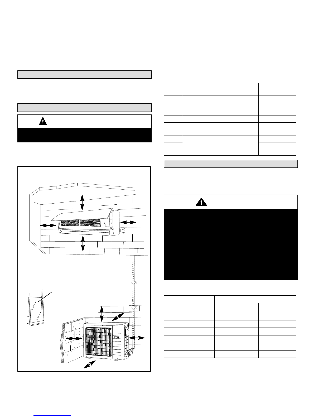
Clearances
CAUTION
In order to avoid injury, take proper precaution when lifting
heavy objects.
SYSTEM CLEARANCES
Refer to figure 2 for mandatory installation clearance
requirements.
MINIMUM INSTALLATION CLEARANCES
A
C
D
B
TABLE 4
MINIMUM SYSTEM CLEARANCES
ID Location
A Clearance between unit and ceiling. 6 in. (152 mm)
B Clearance between unit and floor. 6 ft.(1829 mm)
C / D Clearance to the right and left of unit. 6 in. (152 mm)
E Clearance above unit. 2 ft. (610 mm)
Clearance between air inlet and
F
structure.
G
Clearance between unit and
H 4 ft. (1219 mm)
structures
I 12 in. (305 mm)
Clearance
Required
12 in. (305 mm)
12 in. (305 mm)
Torque Requirements for Caps and Fasteners
When servicing or repairing HVAC components, ensure the
fasteners are appropriately tightened. Table 5 provides
torque values for fasteners.
IMPORTANT
Only use Allen wrenches of sufficient hardness (50Rc Rockwell Harness Scale minimum). Fully insert the
wrench into the valve stem recess.
Service valve stems are factory-torqued (from 9 ft-lbs for
small valves, to 25 ft-lbs for large valves) to prevent
refrigerant loss during shipping and handling. Using an
Allen wrench rated at less than 50Rc risks rounding or
breaking off the wrench, or stripping the valve stem
recess.
See the Lennox Service and Application Notes #C-08-1
for further details and information.
INSTALL UNIT AWAY
FROM WINDOWS
E
I
H
FIGURE 2
MS8C / MS8H (208-230V)
TABLE 5
TORQUE REQUIREMENTS
Recommended Torque
F
G
Parts
Service valve cap 8 ft.- lb. 11
Sheet metal screws 16 in.- lb. 2
Machine screws #10 27 in.- lb. 3
Compressor bolts 7 ft.- lb. 10
Gauge port seal cap 8 ft.- lb. 11
*The United States customary system (also called American system) is a
system of measurement commonly used in the United States. This system
is based on the British Imperial System.
United States
Customary
System*
Metric
(Newton Meter)
Page 8
Page 9
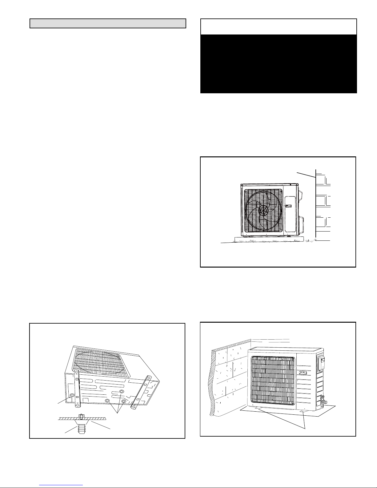
Setting Outdoor Unit
OUTDOOR UNIT POSITIONING CONSIDERATIONS
(AIR CONDITIONER OR HEAT PUMP)
Consider the following when positioning the unit:
* Some localities are adopting sound ordinances based
on the unit's sound level registered from the adjacent
property, not from the property where the unit is
installed. Install the unit as far as possible from the
property line.
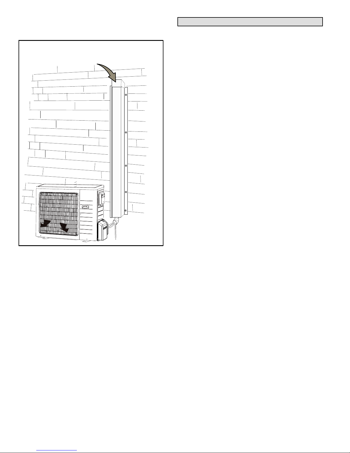
* When possible, do not install the unit directly outside a
window. Glass has a very high level of sound
transmission. For proper placement of unit in relation
to a window see the provided illustration in figure 2.
* Install unit level or, if on a slope, maintain slope
tolerance of 2 degrees [or 2 inches per 5 feet (50 mm
per 1.5 m)] away from building structure.
* Install the unit high enough above the ground or roof to
allow adequate drainage of defrost water and prevent
ice or snow build-up (required for heat pumps).
* In heavy snow areas, do not locate the unit where
drifting will occur. The unit base should be elevated
above the depth of average snows.
* When installed in areas where low ambient
temperatures exist, locate unit so winter prevailing
winds do not blow directly onto outdoor unit.
* Locate unit away from overhanging roof lines which
would allow water or ice to drop on, or in front of, coil
or into unit.
CONDENSATE DRAINAGE REQUIREMENT
(HEAT PUMP ONLY)
Condensate formed during the heating and defrost
processes must be drained from heat pump units. Drain
holes are provided in the base of the units to ensure proper
drainage. Heat pumps must be raised when installed on a
concrete pad or the ground to allow drainage to occur. If the
heat pump unit is installed on a wall mounting bracket,
insert the provided drain connector into one of the 1 inch
(25mm) drain holes and attached a field-provided insulated
drain hose to the connector. Use the provided rubber plugs
to cover any unused drain holes (figure 3).
NOTICE
Roof Damage!
This system contains both refrigerant and oil. Some
rubber roofing material may absorb oil. This will cause
the rubber to swell when it comes into contact with oil.
The rubber will then bubble and could cause leaks.
Protect the roof surface to avoid exposure to refrigerant
and oil during service and installation. Failure to follow
this notice could result in damage to roof surface.
SLAB OR ROOF MOUNTING
Install the unit a minimum of 4 inches (102 mm) above the
roof or ground surface to avoid ice build-up around the unit.
Locate the unit above a load bearing wall or area of the roof
that can adequately support the unit. Consult local codes
for rooftop applications (figure 4).
SLOPE TOLERANCE
BUILDING STRUCTURE
GROUND
LEVEL
Install unit level or maintain slope tolerance of 2
degrees (or 2 inches per 5 feet [50 mm per 1.5 m])
away from building structure.
FIGURE 4
SECURING OUTDOOR UNIT TO SLAB OR FRAME
If the outdoor unit is installed on a field-provided slab or
frame, use lag bolts or equivalent to secure the outdoor unit
to the slab or frame (figure 5).
CONDENSATE DRAINAGE (HEAT PUMPS
ONLY -- UNIT INSTALLED ON FIELD-PROVIDED
WALL-MOUNTING FRAME)
DRAIN
CONNECTOR
DRAIN
CONNECTOR
DRAIN PLUGS
CHASSIS
FIGURE 3
Page 9
SECURING OUTDOOR UNIT TO SLAB
FOUR
FIELD-PROVIDED
ANCHOR BOLTS
FIGURE 5
Corp. 1244-L9
Page 10
PREVAILING WINDS (HEAT PUMP ONLY)
If unit coil cannot be installed away from prevailing winter
winds, a wind barrier should be constructed. Size barrier at
least the same height and width as outdoor unit. Install
barrier 12 inches minimum (305 mm) from the sides of the
unit in the direction of prevailing winds as illustrated.
PREVAILING WIND BARRIER
PREVAILING WINTER WINDS
WIND BARRIER
INLET AIR
12” (305 MM) MINIMUM DISTANCE
DISCHARGE AIR
FIGURE 6
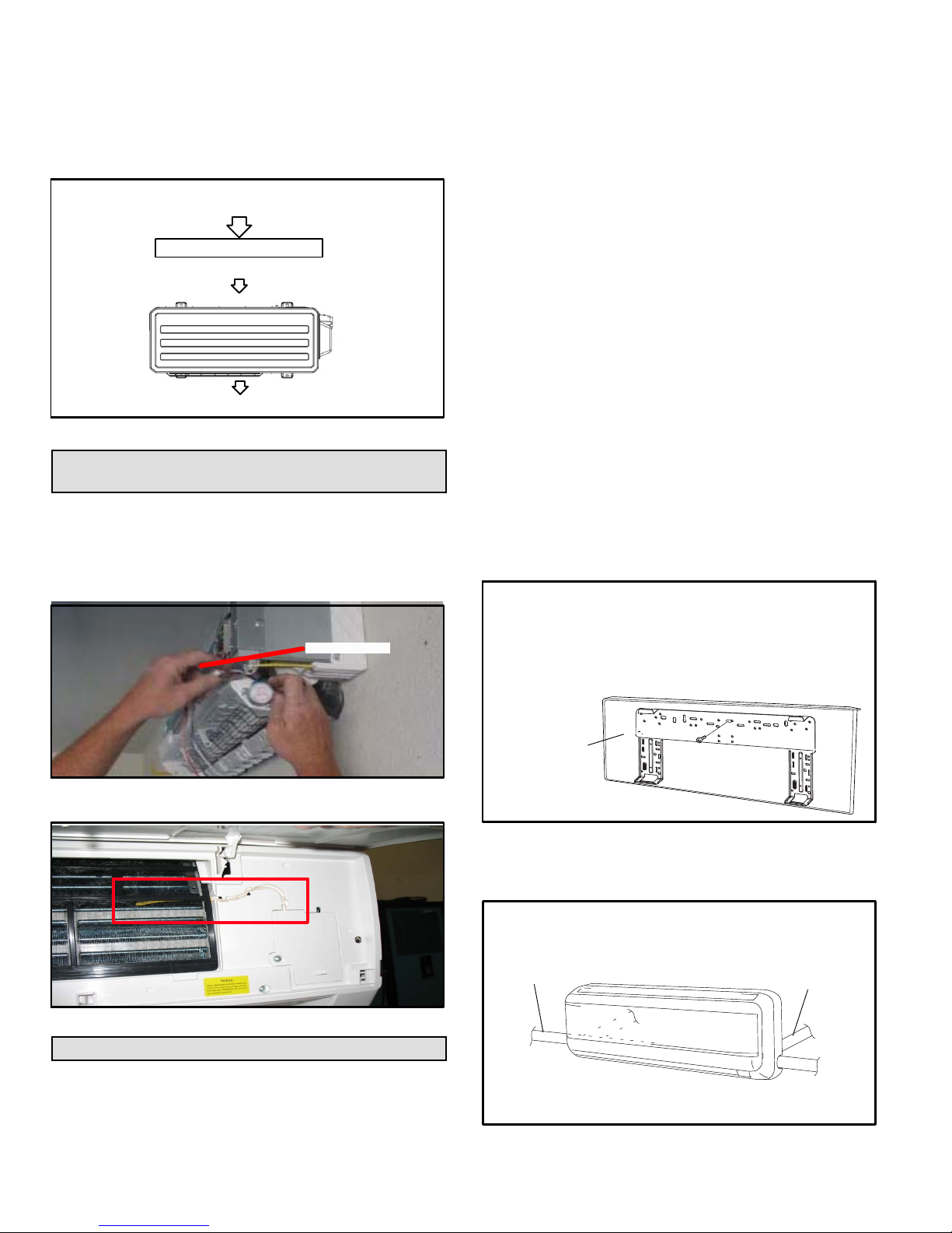
Repositioning Indoor Air Temperature
Sensor
The indoor temperature sensor may be installed in an
alternate location to facilitate shipping (figure 7). It is
recommend that the sensor is relocated to the proper
position shown in figure 8. Refer to the procedure on page
for removal of the front cover.
SHIPPING LOCATION
SENSOR
AVOID
1. Direct sunlight if possible.
2. Locating unit less than 3-1/4” (1 meter) away from
combustible materials and vapors.
3. Locating unit near heat sources which could affect
system performance.
DO:
1. Locate the indoor unit where the room can be uniformly
cooled. Install unit as high as possible on the wall for
best performance.
2. Select a wall location that can support the weight of the
unit.
3. Select a location where line set and condensate line will
have the shortest run to the outside of the structure.
4. Allow sufficient space around unit for proper operation
and maintenance.
5. Consider vertical rise between the indoor unit and
outdoor unit. Do not exceed the maximum vertical line
rise of the line set between the indoor unit and outdoor
unit (table 12).
6. Install the indoor unit a minimum of 36 inches (914 mm)
away from any antenna, power cords (lines), radio,
telephone, security system, or intercom. Electrical
noise and radio frequencies from any of these sources
may affect operation.
DETERMINING WALL MOUNTING BRACKET
LOCATION
1. Remove the wall mounting bracket from the indoor unit.
WALL MOUNTING BRACKET REMOVAL
FROM INDOOR UNIT
A. Remove the shipping screw that secures the
wall mounting bracket to the rear of the unit.
B. Remove bracket from rear panel of indoor unit.
FIGURE 7
CORRECT
LOCATION
FIGURE 8
Indoor Unit Placement and Preparation
INDOOR UNIT LOCATION
Minimum clearances must be maintained as specified in
figure 2. In addition, the following items should be
considered:
MS8C / MS8H (208-230V)
Page 10
REAR OF UNIT
FIGURE 9
2. Determine the optimal exit location for bundle (line set,
condensate line and wiring.
DETERMINING EXIT LOCATION
CONDENSATE/
REFRIGERANT
LINE EXIT LEFT
CONDENSATE/
REFRIGERANT LINE
EXIT LEFT REAR
CONDENSATE/
REFRIGERANT LINE
EXIT RIGHT REAR
(RECOMMENDED)
CONDENSATE/
REFRIGERANT
LINE EXIT RIGHT
FIGURE 10
Page 11
NOTE — If opposite-side exit is preferred, see figure 18 to
switch condensate line and drain cap.
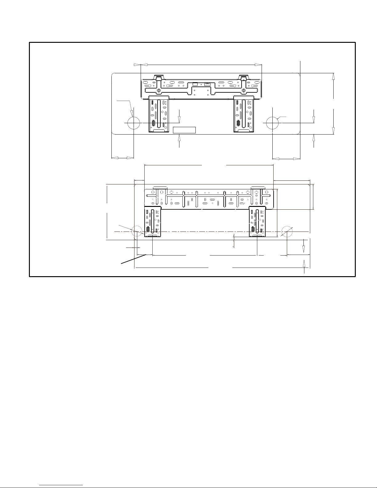
3. Use the wall mounting bracket as a template to
CONDENSATE / REFRIGERANT PIPING REAR EXIT LOCATIONS
2-3/16”
(55)
09 − 12 kBtu
determine the exit point for the line set, condensate line
and indoor / outdoor cable (figure 11).
21-5/16” (542)
2-3/16”
(55)
10-7/8”
(275)
18 kBtu
11-3/4”
(298)
3-1/4”
4”
(100)
2-3/16”
(55)
5/8” (16)
(82)
2-1/8”
(55)
2” (50)
22-3/16”
(563)
FIGURE 11
27-5/16”
(694)
5/8” (16)
33-1/4”
(945)
6-1/4”
(160)
5” (124)
7-3/4”
256
2-3/16”
(55)
(197)
2” (50)
1-3/4” (45)
4-7/8”
(124)
5-5/16”
(136)
Page 11
Corp. 1244-L9
Page 12
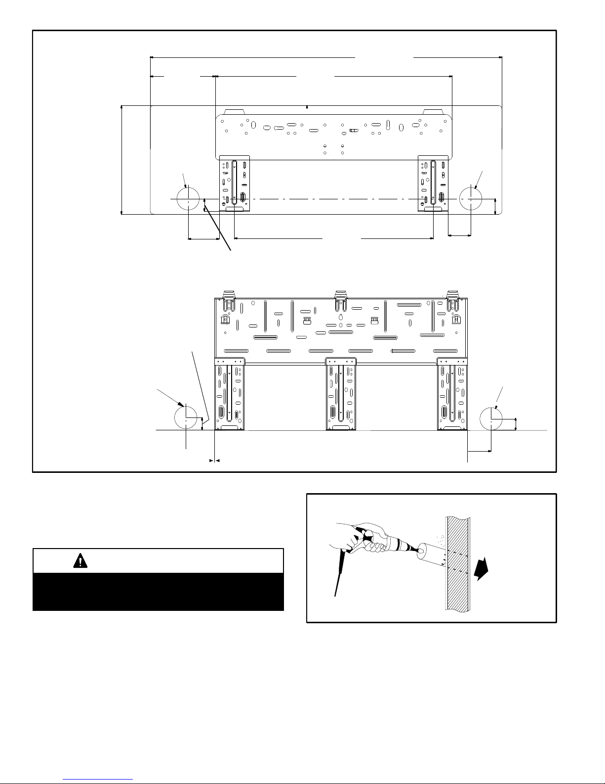
7-7/16”
(189)
40-1/8” (1018)
27 (685)
24 kBtu
30 kBtu
2-9/16”
(65)
2-9/16”
(65)
1” (25)
3-1/2”
(90)
4”
(102)
1-7/16” (36)
22-5/8”
(575)
2-1/2”
(65)
2-9/16”
(65)
4”
(102)
1-3/4”
(45)
2-9/16”
(65)
1“ (25)
INSTALLING WALL SLEEVE
1. Prior to making the hole, check to ensure that neither
studs nor plumbing are directly located behind the hole
location.
CAUTION
Electric Shock Hazard. Can cause injury or death. Avoid
location where electric wiring or conduits may be present
inside the wall.
2. Use either a sabre saw, key hole saw or hole-cutting
drill attachment to cut a 2-3/16-inch (55 mm) diameter
hole in the wall. Hole should be at a slight downward
slant - 3/16” to 3/8” (5 to 10 mm) to the outdoor side.
MS8C / MS8H (208-230V)
FIGURE 12
BORING HOLE FOR WALL SLEEVE
INSIDE
OUTSIDE
FIGURE 13
3. Measure the thickness of the wall from the inside edge
to the outside edge and cut a field-provided PVC pipe
Page 12
Page 13
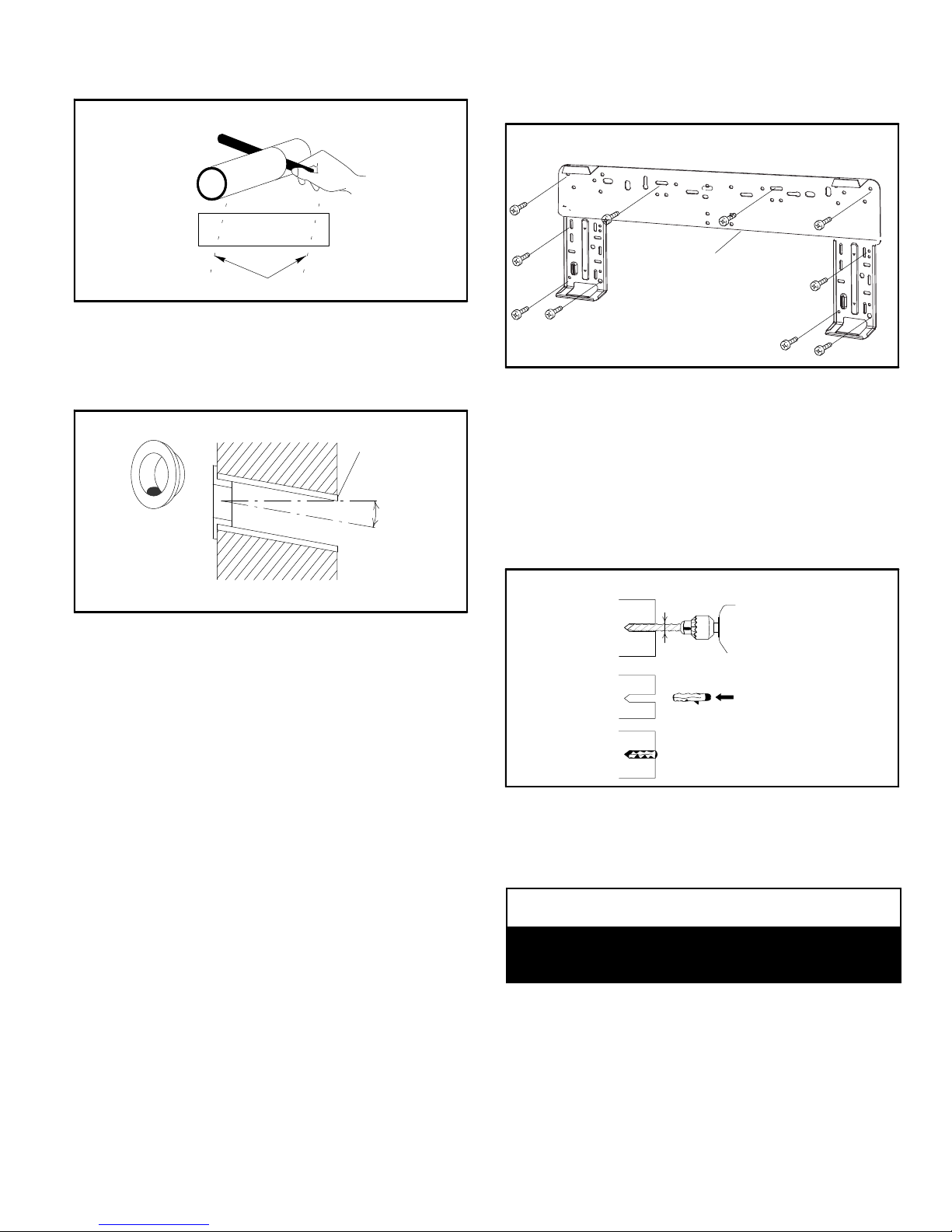
at a slight angle 1/4” (6 mm) shorter than the thickness
of the wall.
CUTTING PVC FOR WALL SLEEVE
CUT PVC FOR WALL SLEEVE AT SLIGHT ANGLE
FIGURE 14
4. Place a field-provided plastic cover over the end of the
pipe that will be visible from the inside wall and insert
the pipe in the wall.
PVC WALL SLEEVE INSTALLATION
PVC PIPE
SLIGHT
PLASTIC COVER
(FIELD PROVIDED)
INSIDE
WALL
ANGLE
OUTSIDE
NOTE
— It is important to use all screws provided to secure
the wall mounting bracket to the wall. Additional holes may
be drilled through the metal wall mounting bracket to better
secure wall bracket to wall studs.
SECURING WALL MOUNTING BRACKET TO WALL
WALL MOUNTING
BRACKET
FIGURE 16
4. The wall mounting bracket must be installed flush
against the wall so that the indoor unit will be flush after
installation. Any space between the wall and unit will
cause noise and vibration.
5. The wall mounting bracket must be installed
horizontally level on the wall.
6. If the wall is made of brick, concrete or other similar
material, then drill pilot holes in the wall. Insert
field-provided plastic anchors for mounting screws.
MASONRY APPLICATIONS
FIGURE 15
SECURE WALL MOUNTING BRACKET TO WALL
Determine that wall will support the weight of the indoor
unit. See table 1 for indoor unit weight. Install the wall
mounting bracket so that is is correctly positioned
horizontally and vertically. The indoor unit must be installed
level on the wall to allow proper condensate drainage.
1. Use a carpenter's level or tape measure to verify the
wall mounting bracket is horizontally level.
2. Secure the wall mounting bracket to the wall using the
provided screws. If possible, align the rear panel screw
holes with wall stud locations marked on the wall.
HINT
— Use the wall mounting bracket as a template to
mark locations where screws will be used.
3. Secure the wall mounting bracket to the wall using as
many screws into studs as possible. All other screws
must be secured using plastic wall anchors.
DRILL PILOT HOLES
USE ANCHORS
INSTALL ANCHORS
FIGURE 17
CONDENSATE DRAIN CONFIGURATION
If the condensate line needs to be moved, use the following
procedure to change the drain line exit location.
NOTICE
Care must be taken when moving the condensate line to
the opposite position to prevent damaging the
condensate line or connector.
Page 13
Corp. 1244-L9
Page 14
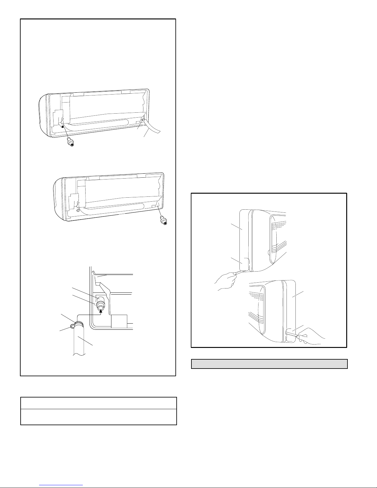
CHANGING CONDENSATE DRAIN LOCATION
(IF NECESSARY)
1. Locate the condensate line and the drain cap
located on unit.
2. Remove the clamp which secures the condensate
line to the drain outlet and pull the line to remove it.
3. Apply moderate force to pull off the drain cap from
the unit.
REAR VIEW OF UNIT
DRAIN CAP
CLAMP
CONDENSATE LINE
4. Re-install the drain cap on the opposite side
drain outlet.
REAR VIEW OF UNIT
1. Confirm proper slope (not less than 1/4 inch per foot)
and routing of condensate lines to ensure moisture is
drained away from the indoor unit (see page 12).
2. Drain should not have any droops or kinks that would
restrict condensate flow and shall be approved
resistant pipe.
3. Condensate drains should be ran as short as possible.
4. Once installation of drain is complete, pour water into
the evaporator drain pan to ensure proper condensate
drainage. If condensate will not properly drain from
evaporator pan, a condensate pump should be added
to system.
5. Confirm proper insulating, taping and bundling of
refrigeration lines, main power lines and drain line (see
page 16).
PREPARING INDOOR UNIT FRAME FOR LEFT- OR
RIGHT-SIDE EXIT OF UTILITY BUNDLE
1. Right- or Left-Side Utility Bundle Exit — Cut out the
corner of the right/left plastic cabinet with a hacksaw or
similar tool (A or B).
2. Right-Rear or Left-Rear Utility Bundle Exit — The
corner of the plastic cabinet does not need to be
modified.
DRAIN CAP
5. Slide the condensate line over the opposite
drain outlet and use the clamp to secure the
line.
REAR VIEW OF UNIT
DRAIN PAN
OUTLET
CLAMP HOOK
LATCH
CLAMP
CLAMP HOOK
CONDENSATE LINE
IMPORTANT — Keep horizontal runs of condensate line external
to unit as short as possible. Condensate line should be properly
sloped to ensure proper drainage.
FIGURE 18
CONDENSATE DRAIN LINE INSTALLATION
IMPORTANT !
Drain should have a slope of not less than ¼ inch per
foot and be approved corrosion resistance pipe.
LEFT- OR RIGHT-SIDE UTILITY EXIT
A
PLASTIC
CABINET
LEFT-SIDE
TUBING OUTLET
B
PLASTIC
CABINET
RIGHT-SIDE
TUBING OUTLET
FIGURE 19
Indoor Unit Cable Connections
NOTE — Stranded wire must be used to connect the
outdoor unit to the indoor unit. The stranded wire is
necessary to ensure proper system communication and
operation.
1. Route the cable (4-conductor, stranded wire, line
voltage, sized per National Electric Code) through the
wall sleeve. Refer to unit nameplate for rated voltage.
MS8C / MS8H (208-230V)
Page 14
Page 15
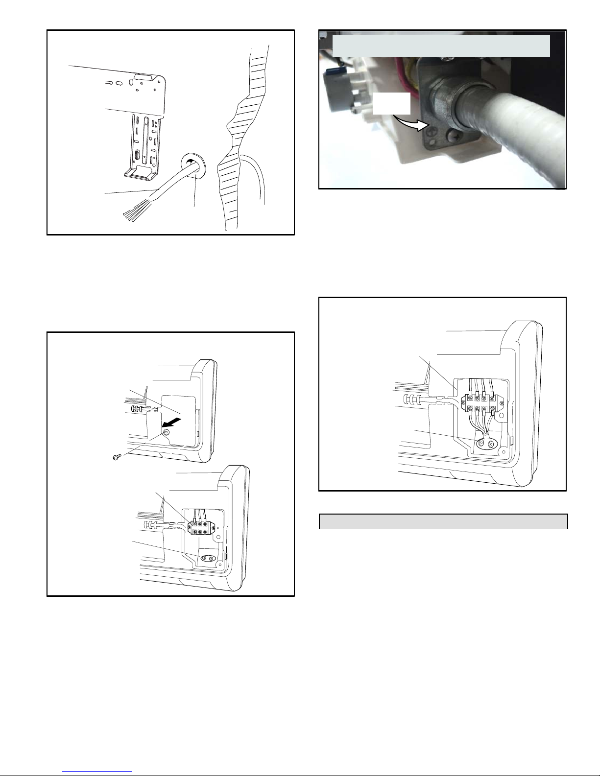
FEED CABLE THROUGH WALL
INDOOR UNIT WALL MOUNTING BRACKET
WALL
WIRING
FIELD-PROVIDED
PVC WALL SLEEVE
FIGURE 20
2. Make sure to provide a sufficient length of cable so that
connections are made to the unit before it is secured to
the wall mounting bracket.
3. Lift indoor unit front panel to access the control box
cover. Remove the screw(s) securing the cover plate.
Remove the plate.
TYPICAL INDOOR UNIT INDOOR UNIT) —
SECURING CABLE / WIRES
CONDUIT
ROUTING
GUIDE
REAR VIEW OF INDOOR UNIT
FIGURE 22
5. Strip the wire insulation to expose the stranded wire.
6. Tightly twist each wire end.
7. Terminal designations for the indoor unit terminal block
are illustrated in figure 30.
8. Use the provided strain relief plate to secure the
terminal block wiring.
TYPICAL INDOOR UNIT TERMINAL BLOCK
AND STRAIN RELIEF
ACCESSING THE INDOOR UNIT TERMINAL BLOCK
TYPICAL
INDOOR UNIT
CONTROL
BOX COVER
TERMINAL
BLOCK
TYPICAL WIRING
STRAIN RELIEF
FIGURE 21
4. Feed cable / wiring through conduit routing guide.
NOTE — A cable routing guide has been factory-installed.
TERMINAL
BLOCK
WIRING STRAIN RELIEF
FIGURE 23
Securing Indoor Unit to Wall Mounting Bracket
1. Shape the refrigerant line set so that it can be guided
either out the back of the indoor unit or through either
side of the indoor unit frame, then through the wall
sleeve to the outside unit.
2. Use field-provided tape to bundle the cable, refrigerant
line set and condensate line together as shown in figure
1.
3. Feed the bundle through the wall sleeve and slide
indoor unit onto upper mounting hooks.
Page 15
Corp. 1244-L9
Page 16
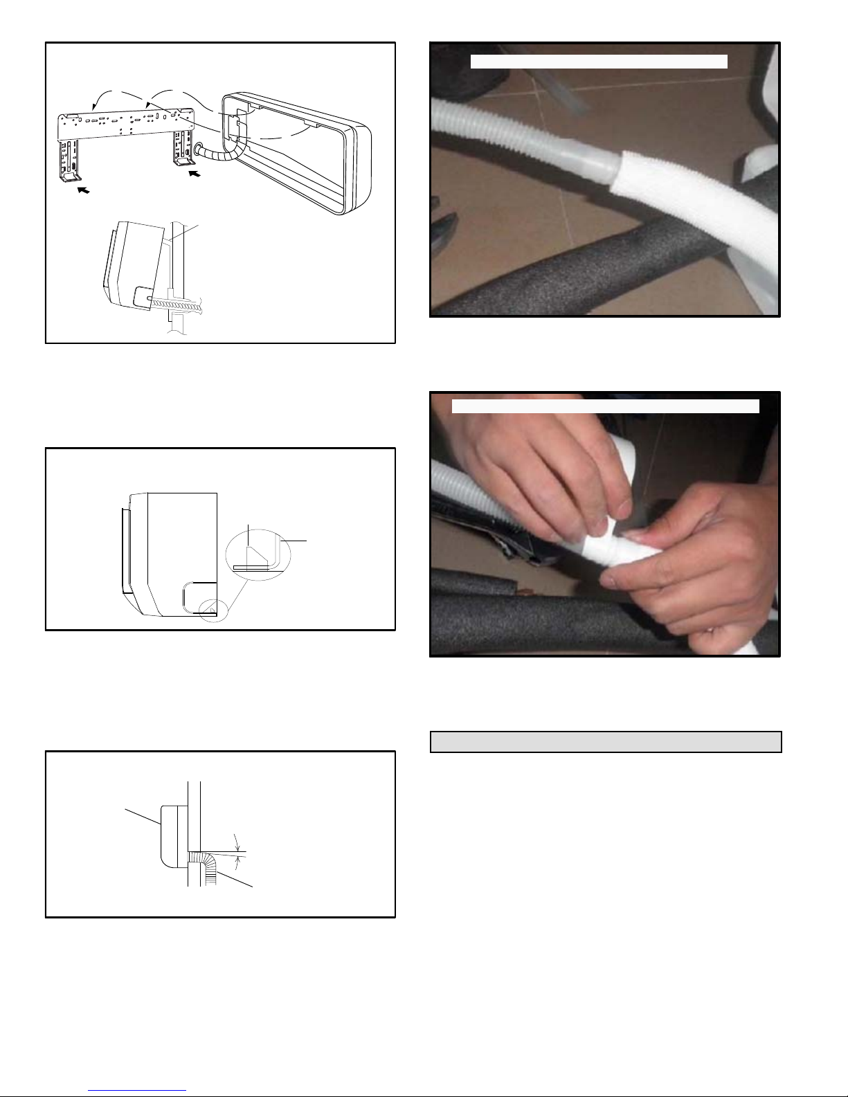
FEED BUNDLE THROUGH WALL SLEEVE
UPPER MOUNTING
HOOKS
PASS BUNDLE
THROUGH WALL
FIGURE 24
CONNECTING CONDENSATE LINE
FIGURE 27
3. Use tape approved for waterproofing line
connections to secure the field-provided pipe to the
factory-installed condensate line.
1. Secure the indoor unit to the wall bracket using the
lower mounting hooks.
SECURE INDOOR UNIT TO WALL MOUNTING
BRACKET
LOWER MOUNTING
HOOKS
FIGURE 25
2. Carefully bend the bundle (line set, condensate line
and cable) to run along the outside wall toward the
outdoor unit. Downward slope of wall sleeve will ensure
proper condensate drainage.
INSTALLED INDOOR UNIT
INDOOR UNIT
SLOPE
TAPING CONDENSATE LINE CONNECTION
FIGURE 28
NOTE — Use a clean, dry cloth to wipe the indoor unit after
installation is complete to remove fingerprints. Do not use
wet cloth, cleansers or solutions.
Outdoor Unit Wiring Connections
In the U.S.A., wiring must conform with current local codes
and the current National Electric Code (NEC). In Canada,
wiring must conform with current local codes and the current
Canadian Electrical Code (CEC).
Refer to unit nameplate for minimum circuit ampacity and
maximum overcurrent protection size.
BUNDLE THROUGH
WALL SLEEVE
FIGURE 26
CONDENSATE LINE
1. Use the provided foam insulation to wrap the
factory-installed condensate line.
2. Connect indoor unit factory-installed condensate line
to field-provided condensate drain pipe.
MS8C / MS8H (208-230V)
MAIN SYSTEM CIRCUIT BREAKER AND OUTDOOR
UNIT DISCONNECT SWITCH
The main system circuit breaker and outdoor unit
disconnect switch should be sized per local codes and unit
requirements.
Local codes may require a disconnect between the indoor
and outdoor units.
INDOOR / OUTDOOR CABLE
Wiring must conform to local and national codes.
Page 16
Page 17
NOTE — Stranded wire must be used to connect the
outdoor unit to the indoor unit. The stranded wire is
necessary to ensure proper system communication and
operation.
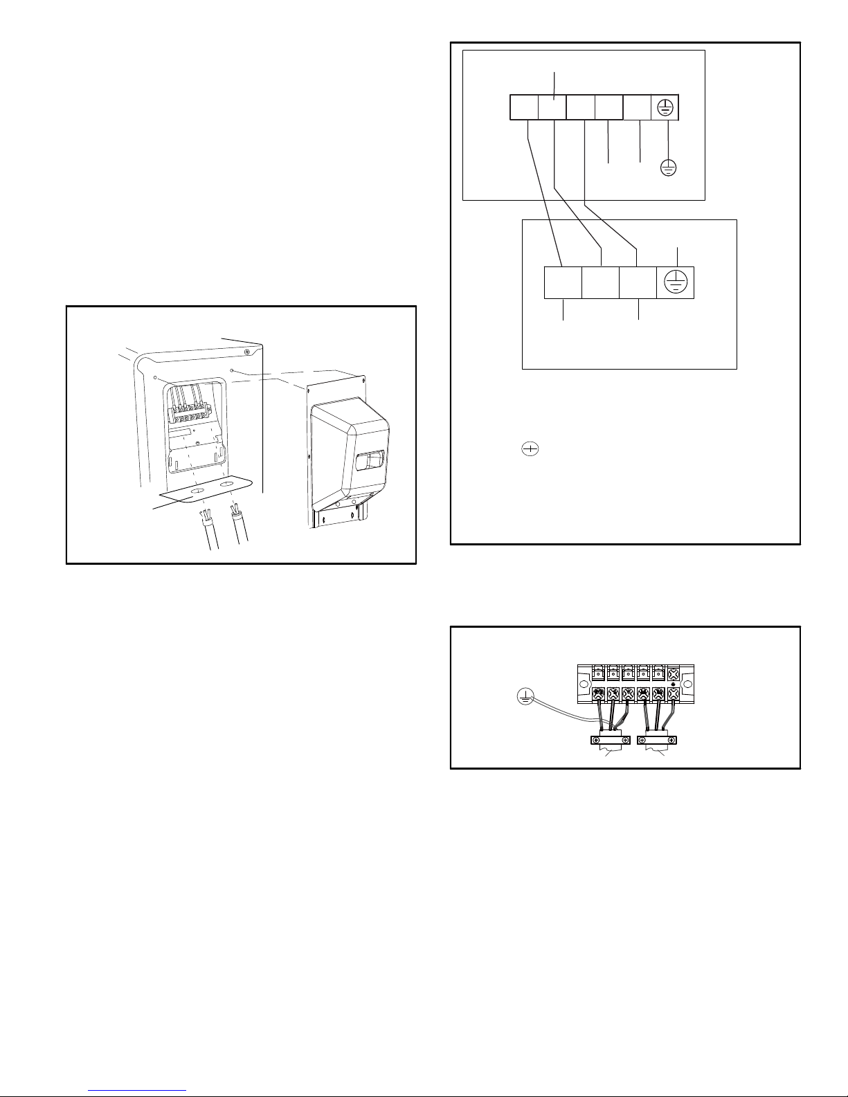
SUPPLY POWER
Size per unit nameplate and local and national codes.
COMMUNICATION
N(1)
23L1
OUTDOOR UNIT
L2
WIRING CONNECTIONS
1. Remove access panel.
2. Route all wiring to outdoor unit through the wire routing
plate.
3. Connect the control wiring and power supply wiring per
the figures that follow.
4. The unit must be grounded according to local codes.
5. Secure wiring using built-in wire strain relief.
OUTDOOR UNIT ELECTRICAL CONNECTIONS
ROUTE WIRES
THROUGH
ROUTING
PLATE
ACCESS PLATE
FIGURE 29
L2
L1
POWER
GROUND
N(1)
(L1)
2
3
(L2)
(COMMUNICATION)
INDOOR UNIT
TERMINAL LEGEND
N(1) = L1
2 = Communication line
3 = L2
= Ground
IMPORTANT
Check indoor to outdoor field wiring to confirm (N) 1
from indoor goes to (N) 1 outdoor, terminal 2 from indoor
goes to terminal 2 outdoors and terminal 3 indoors goes
to terminal 3 in outdoor.
FIGURE 30
6. Connect the green/yellow ground wire to the ground
terminal.
7. Use the strain relief to secure the cabling (figure 31).
TYPICAL UNIT STRAIN RELIEF
OUTDOOR UNIT
TERMINAL BLOCK
TO INDOOR UNIT
TO POWER SUPPLY
FIGURE 31
WIRING DIAGRAM SYMBOLS AND COLOR CODES
The following tables identify the wiring color codes
and ground symbol used in the following wiring
diagrams.
Page 17
Corp. 1244-L9
Page 18
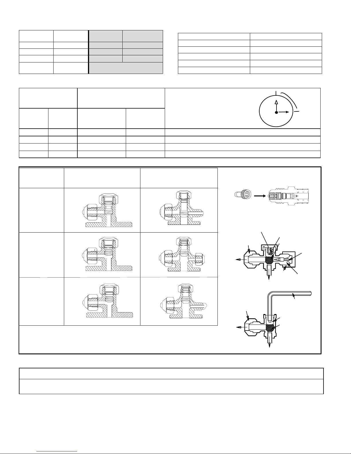
TABLE 6
WIRE COLOR CODES
CODE CODE COLOR
WH WHITE BN BROWN
YE YELLOW BU BLUE
RD RED BK BLACK
YEGN
YELLOW
GREEN
COLOR CODE
OR SYMBOL
Table 8. Valve Caps Torque Recommendations
COLOR
TABLE 7
SYMBOLS
SYMBOL PARTS NAME
L1 REACTOR (CHOKE)
PCB1-PCB2 PRINTED CIRCUIT BOARD
S10/S11S40/S70/S80/S90 CONNECTOR
SAT OVERLOAD
COMP COMPRESSOR
Outside Diameter Recommended Torque
Inches
1/4” 6.35 11 - 14-3/4 ft.- lb. 15 ~ 20 N*m
3/8” 9.52 26 - 29-1/2 ft.- lb. 35 ~ 40 N*m 1/2 turn
1/2” 12.70 44-1/4 - 48 ft.- lb. 60 ~ 65 N*m 7/8 turn
5/8” 16 51-5/8 - 55-1/4 ft.- lb. 70 ~ 75 N*m 1 full turn
Action
mm U.S. Metric
2-Way
Shut-Off Valve
No torque wrench available?
Finger tighten and use an
appropriately sized wrench to turn an
additional:
1/4 turn
3-Way
Service Valve
HOSE WITH
SCHRADER VALVE
CLOSED
Evacuating with a
vacuum pump
REQUIRES FIELD-PROVIDED 5/16”
FEMALE FLARE TO 1/4” MALE FLARE
ADAPTER.
FULLY
OPEN
FLARE CAP
Outdoor unit
running
TO LINE
SET
11
10
9
8
PUSH
VALVE CAP
12
1
2
3
4
5
7
6
3-WAY SERVICE
VALV E
OPEN POSITION
CLOSED POSITION
1/4 TURN
PIN
SERVICE
PORT
FULLY
OPEN
SERVICE
PORT CAP
TO OUTDOOR UNIT
Checking
pressure and
adding refrigerant
TO LINE
SET
FLARE CAP
TO OUTDOOR UNIT
ALLEN WRENCH
(5 MM)
OPEN POSITION
CLOSED POSITION
FIGURE 32
IMPORTANT !
To prevent stripping of the various caps, use an appropriately sized wrench and fit the wrench snugly over the cap before
tightening.
MS8C / MS8H (208-230V)
Page 18
Page 19

Operating Service Valves
The large line service valve on the outdoor unit is used to
purge air, test for leaks, check operating pressures and add
refrigerant to system. The 3-way service valve is equipped
with a service port which has a factory-installed valve core.
Figure 32 provides information on how to access and
operate the 3-way service and 2-way shut-off valves.
IMPORTANT
To prevent stripping of the various caps, use an
appropriately sized wrench and fit the wrench snugly over
the cap before tightening.
Page 19
Corp. 1244-L9
Page 20
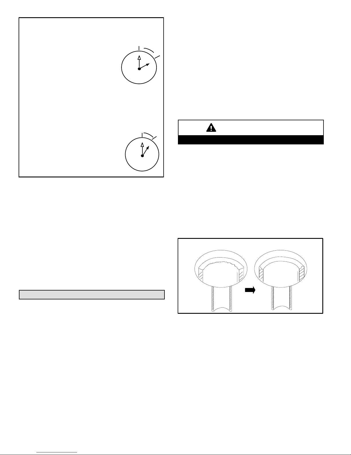
TIGHTENING SERVICE VALVE CAPS
To Access Service Port:
12
6
1/6
TURN
1
5
2
3
4
A service port cap protects the service port core
from contamination and serves as the primary
leak seal.
1. Remove service port cap with an
appropriately sized wrench.
2. Connect gauge set to service port.
3. When testing is complete, replace service
port cap and tighten as follows:
* With torque wrench: Finger tighten and torque cap per table
5.
* Without torque wrench: Finger tighten and use an appropri
ately sized wrench to turn an additional 1/6 turn clockwise.
10
9
11
8
7
Reinstall Stem Cap:
11
1/12
TURN
12
1
2
3
4
5
7
6
Stem cap protects the valve stem from damage
and serves as the primary seal. Replace the
stem cap and tighten as follows:
* With Torque Wrench: Finger tighten, then
torque cap per table 5.
* Without Torque Wrench: Finger tighten,
then use an appropriately sized wrench
to turn an additional 1/12 turn clockwise.
10
9
8
FIGURE 33
USING MANIFOLD GAUGE SET
When checking the system charge, only use a manifold
gauge set that features low-loss, anti-blow-back fittings.
Manifold gauge set used for HFC-410A refrigerant systems
must be capable of handling the higher system operating
pressures. The manifold gauges should be rated for:
* High side — Pressure range of 0 - 800 pound-force per
square inch gauge (psig)
* Low side — Use with 30” vacuum to 250 psig with
dampened speed to 500 psig
* Manifold gauge set hoses must be rated for use up to
800 psig of pressure with a 4000 psig burst rating.
connections and sizes as listed in table 12.
Seal and isolate the opening where the bundle (including
refrigerant lines) passes through so vibration is not
transmitted to the building. Pay close attention to line set
isolation during installation of any HVAC system. When
properly isolated from building structures (walls, ceilings.
floors), the refrigerant lines will not create unnecessary
vibration and subsequent sound. Line set must be
insulated.
LINE SET LENGTH AND ELEVATION
Capacity is based on standard line set length and maximum
allowable length and elevation (table 12).
Minimum line set length for all sizes is 10 feet (3 meters).
IMPORTANT
Mineral oils are not compatible with HFC-410A.
LINE SET CONNECTIONS
Line connections are made to the outdoor unit using
field-provided flare nuts.
Remove the service valve cover from the outdoor unit.
FLARING PROCEDURE
1. Use a tube cutter to cut the copper line set to the
required length. Cut the lines approximately 12” to 20”
(305 mm to 508 mm) longer than the estimated
required length.
2. Use a pipe reamer or file to remove burrs at the end of
the line set.
DE-BURRING LINE SET
BEFORE
AFTER
Line Set Requirements
This section provides information on installation of the
field-provided line set.
LINE SET INSTALLATION
Field piping consists of two lines from the outdoor unit to the
indoor unit. Use field-fabricated line set with flare
MS8C / MS8H (208-230V)
FIGURE 34
3. Remove flare nut from outdoor unit and slide it onto the
copper tube.
4. Use a flaring tool to flare the end of the copper tube.
Page 20
Page 21
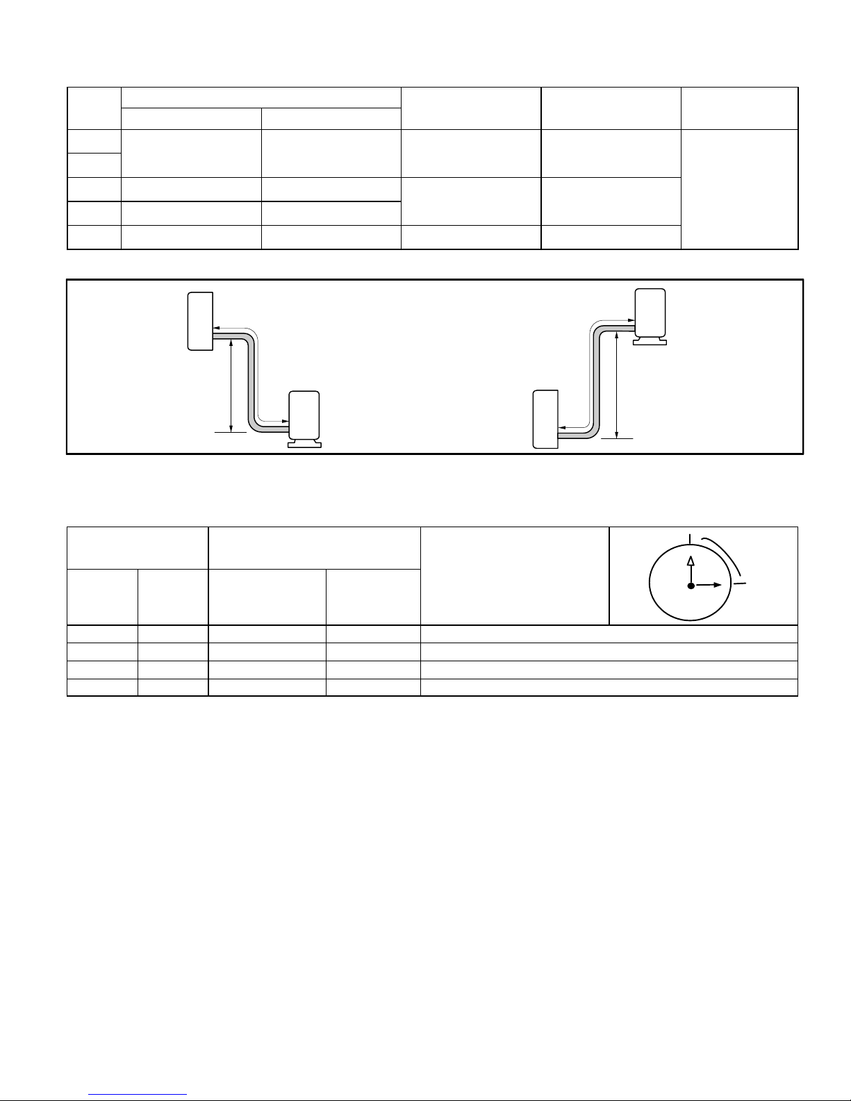
TABLE 9
REFRIGERANT LINE SET REQUIREMENTS, LENGTH AND HEIGHT LIMITATIONS AND OUTDOOR UNIT
REFRIGERANT METERING DEVICE TYPE (AIR CONDITIONER AND HEAT PUMP SYSTEMS)
System
Size
(kBtu)
Small Line Large Line
-09
1/4 in. (6 mm) 3/8 in. (9.5 mm) 33 feet (10 m) 66 Feet (20 m)
-12
-18 1/4 in. (6 mm) 1/2 in. (12 mm)
-24 1/4 in. (6 mm) 5/8 in. (16 mm)
-30 1/4 in. (6 mm) 5/8 in. 16 mm) 33 feet (10 m) 98 Feet (30 m)
Line Set Diameters
Maximum Line Set
Elevation
49 feet (15 m) 98 Feet (30 m)
Maximum Line Set
Length
Electronic Expansion
Note - Minimum line set length for all sizes is 10 feet (3 meters).
LINE SET LENGTH AND ELEVATION
Refrigerant
Metering Device
Type
Valve
INDOOR UNIT
Maximum Line
Set Elevation
Maximum Line Set Length
OUTDOOR UNIT
Maximum Line Set
Length
INDOOR UNIT
FIGURE 35
TABLE 10
TORQUE SPECIFICATIONS
Outside Diameter Recommended Torque
Inches
1/4” 6.35 15 ft.- lb. 20
3/8” 9.52 26 ft.- lb. 35 1/2 turn
1/2” 12.70 41 ft.- lb. 55 7/8 turn
5/8” 15.88 48 ft.- Ib. 65 1 full turn
mm U.S.
Metric (Newton
Meter)
No torque wrench available
Finger tighten and use an
appropriately sized wrench to turn an
additional:
1/4 turn
OUTDOOR UNIT
Maximum Line
Set Elevation
12
11
10
9
8
7
6
1
2
1/4 TURN
3
4
5
Page 21
Corp. 1244-L9
Page 22
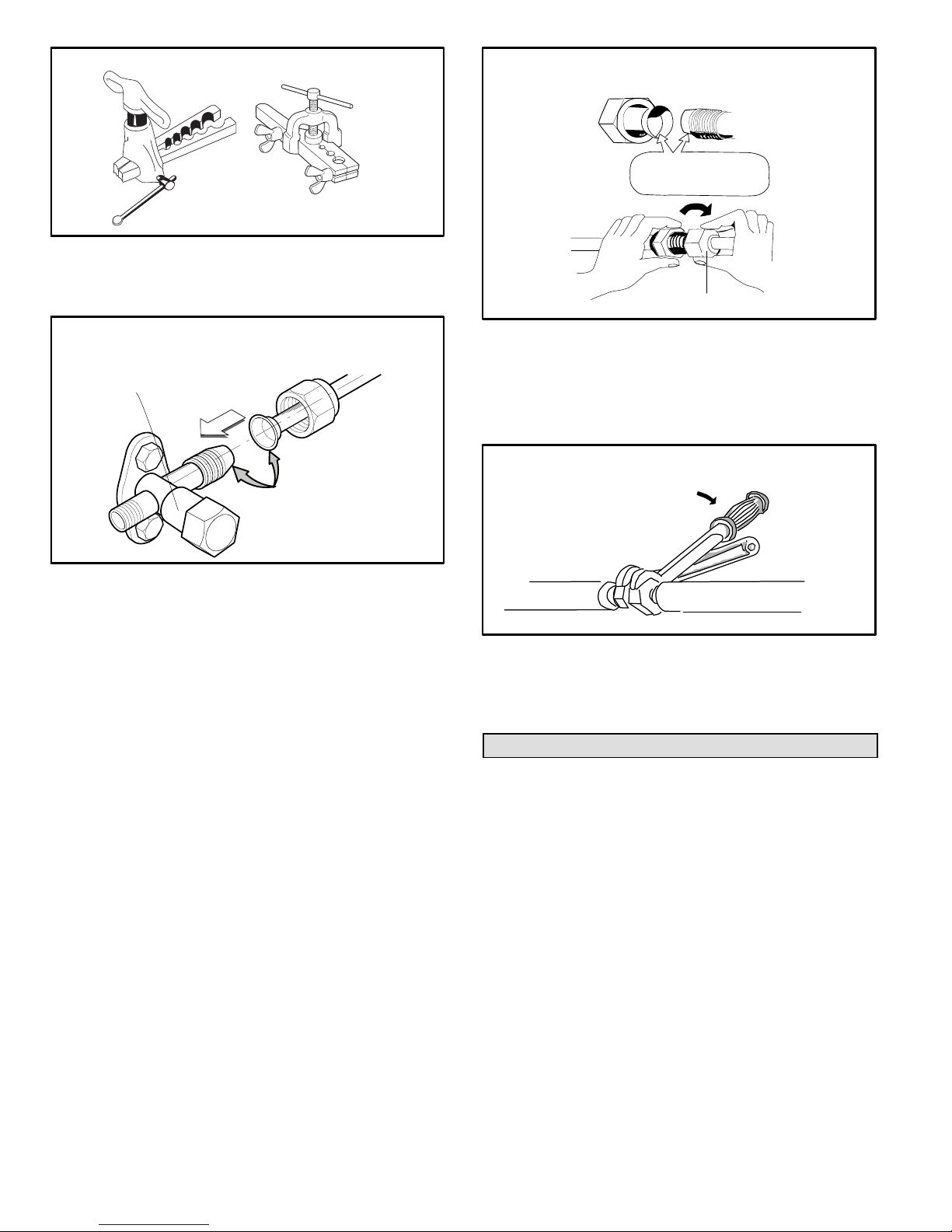
FLARING TOOLS
MAKING CONNECTIONS AT INDOOR UNIT
(MALE TO FEMALE CONNECTION)
A
APPLY REFRIGERANT
LUBRICANT HERE
CLUTCH TYPE
WING NUT TYPE
FIGURE 36
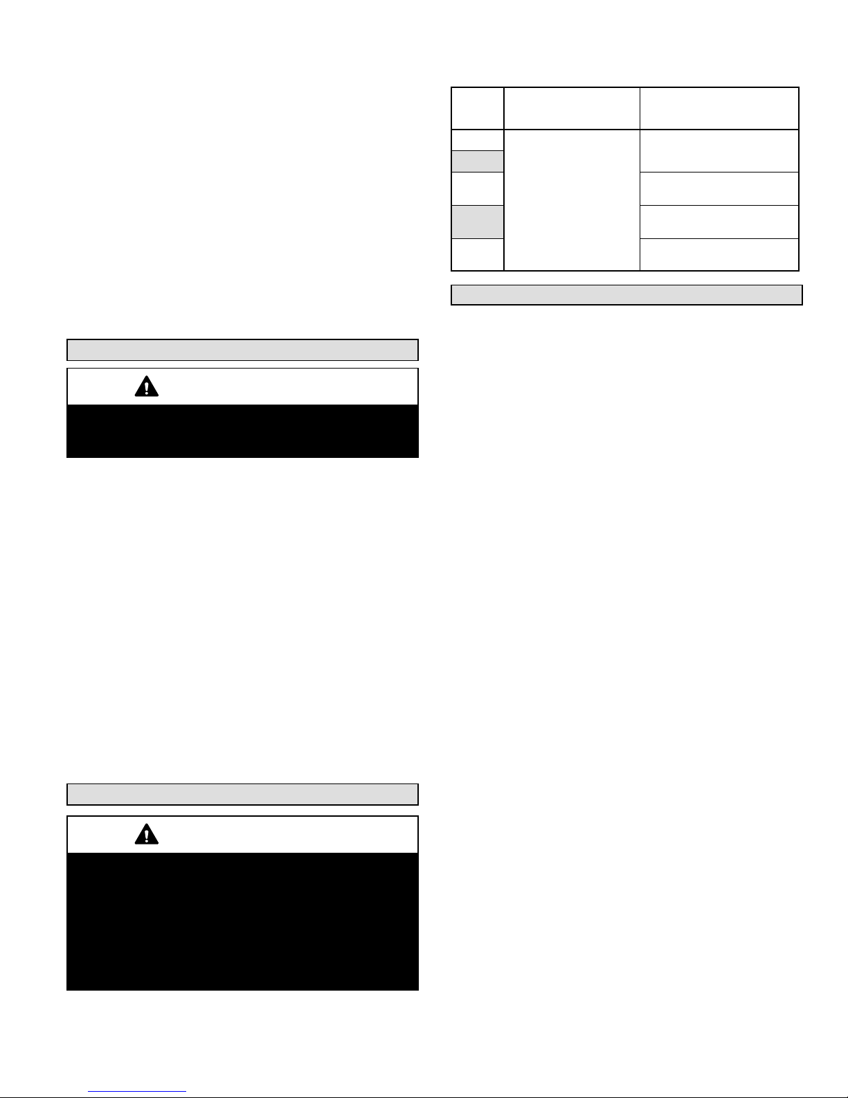
TYPICAL LINE SET CONNECTION TO
OUTDOOR UNIT
2-WAY LARGE LINE
SERVICE PORT
B
A
APPLY REFRIGERANT
LUBRICANT HERE
FIGURE 37
CONNECTING LINE SET TO OUTDOOR UNIT
1. Apply a sealing cap or water-proof tape to prevent dust
or water from getting into the refrigerant piping before
it is connected.
2. Apply refrigerant lubricant to the matching surfaces of
the flared line set and union before connecting them
together (figure 37 -- A). This will reduce refrigerant
leaks.
3. Align the flared refrigerant line with valve connection,
then tighten the flare nut lightly at first to obtain a
smooth match (figure 37 - B).
4. Tighten flare nuts. Do not over-tighten a flared joint.
Once snug, continue another half turn on each nut.
That should provide a gas-tight joint. You may also use
a torque wrench to tighten nuts using table 10
recommendations.
CONNECTING LINE SET BETWEEN INDOOR AND
OUTDOOR UNITS
1. Apply a sealing cap or water-proof tape to prevent dust
or water from getting into the refrigerant piping before
it is connected.
2. Apply refrigerant lubricant to the matching surfaces of
the flared line set and union before connecting them
together (figure 38 -- A).
3. Align the union tube and flared refrigerant line with
each other, then tighten the flare nut lightly at first to
obtain a smooth match (figure 38 -- B).
B
MALE FLARE CONNECTION
FIGURE 38
4. Tighten flare nuts. Do not over-tighten a flared joint.
Once snug, continue another half turn on each nut.
That should be a leak-free joint. You may also use a
torque wrench to tighten nuts using table 10
recommendations.
TIGHTEN FLARE NUT
TORQUE
WRENCH
TO INDOOR
UNIT
TO OUTDOOR UNIT
BACKUP
WRENCH
FIGURE 39
The line set between the indoor and outdoor unit must be
leak tested and evacuated to remove any noncondensables and moisture from the system.
Leak Test and Evacuation
Air and moisture remaining in the refrigerant system will
have undesirable effects as indicated below:
* Pressure in the system rises
* Operating current rises
* Cooling or heating efficiency drops
* Moisture in the refrigerant circuit may freeze and block
capillary tubing (-30 size only)
* Water may lead to corrosion of parts in the refrigeration
system
The line set between the indoor and outdoor unit must be
leak tested and evacuated to remove any noncondensables and moisture from the system.
LEAK TEST
1. Connect the manifold gauge set and dry nitrogen gas
cylinder to the large line service port as illustrated in
figure 40.
2. Pressurize the system to no more than 150 PSIG with
dry nitrogen. Check for leaks using soapy water.
3. After the system is found to be free of leaks, relieve the
nitrogen pressure by loosening the charge hose
MS8C / MS8H (208-230V)
Page 22
Page 23
connector at the nitrogen cylinder. When the system
pressure is reduced to normal, disconnect the hose
from the cylinder.
EVACUATION
1. Connect the gauge set, micron gauge and vacuum
pump as shown in figure 40.
2. The operation time for evacuation varies with the line
set length and capacity of the pump. Allow the pump to
operate until the system has been evacuated down to
300 microns. Allow the pump to continue running for an
additional 15 minutes.
3. Turn off the pump and leave the connections secured
to the 3-way service valve. After five minutes, if the
system fails to hold 500 microns or less, check all
connections for tight fit and repeat the evacuation
procedure.
4. When the desired vacuum is reached, close the low
knob of the manifold valve and stop the vacuum pump.
Unit Start-Up
IMPORTANT
If unit is equipped with a crankcase heater, it should be
energized 24 hours before unit start-up to prevent
compressor damage as a result of slugging.
UNIT START-UP
1. Inspect all factory- and field-installed wiring for loose
connections.
2. Verify that the manifold gauge set is connected as
illustrated in figure 40.
3. Open the 3-way service and two-way shut off valves to
release the refrigerant charge contained in outdoor unit
into the system.
4. Replace the stem caps and tighten to the value listed
in table 5.
5. Check voltage supply at the outdoor unit terminal strip.
The voltage must be within the range listed on the unit's
nameplate. If not, do not start the equipment until you
have consulted with the power company and the
voltage condition has been corrected.
6. Refer to the included user guide to operate the system
using the provided remote control.
7. Visually check for binding of both indoor and outdoor
fans.
Adding Refrigerant for Longer Line Set
IMPORTANT
FV50S PVE is the ONLY acceptable oil for Lennox MS7
and MS8 mini-split systems.
Polyvinylether (PVE) is an innovative refrigerant oil
specially formulated for hydrofluorocarbon (HFC)
refrigeration systems. In addition to providing lubricating
properties, it also has a number of other applied
advantages that help to increase the reliability of the
refrigeration systems where it is applied.
1. Open the low side manifold gauge valve and weigh in
liquid refrigerant. Use table 12 to calculate the correct
weigh-in charge.
2. Close manifold gauge valves.
Table 11. Line Set Length and Adding Refrigerant
System
Size
(kBtu)
-09
-12
-18
-24
-30
Base Charge (outdoor
unit is sufficient for up
to listed length below)
26 feet (8 m)
Add Refrigerant
1 ounces per 40 inches (30
grams per meter)
0.71 ounces per 40 inches
(20 grams per meter)
1 ounces per 40 inches (30
grams per meter)
2 ounces per 40 inches (50
grams per meter)
Checking Large Line Operating Pressures
Connect gauge set to service port as illustrated in figure 40.
1. Indoor temperatures should be between 70F and 86F
(21C and 30C). Outdoor temperatures should be
between 23F to 118F (-5C to 48C).
2. Turn the remote control I FEEL function ON.
3. Set all indoor zone remote controls to lowest setting
61F {16C} in the Cool mode.
4. Turn ON the TURBO function. (Note: Allow 3 minutes
for compressor delay to time out).
5. Allow the system to operate for a minimum of 10
minutes before doing system checks: Indoor air coil
temperature drop (Range of 18 to 24F (10 to 13C).
Refrigerant pressure on big line. (Use pressure
ranges noted in table 12 for general guides. Minor
variations in these pressures may be expected due
to differences in installations).
HEATING
1. Indoor temperatures should be between 61F and 70F
(16C and 21C). Outdoor temperatures should be
between 5F to 80F (-15C to 27C)
2. Set all indoor zone remote controls to highest setting
86F {30C} in the Heat mode.
3. Turn the remote control I FEEL function ON.
4. Turn ON the TURBO function. (Note: Allow 3 minutes
for compressor delay to time out).
5. Allow the system to operate for a minimum of 10
minutes before doing system before checking:
Refrigerant pressure on big line. (Use pressure
ranges noted in table 12 for general guides. Minor
variations in these pressures may be expected due
to differences in installations).
IMPORTANT
If the operating pressures do not fall within the ranges given
in the pressure table:
A. Check the indoor or outdoor unit displays for error
code(s).
B. Refer to troubleshooting procedure diagrams in
Service and Installation manual to verify
component operation.
If no issues are found, follow the weigh-in charging
procedure below to charge the system.
Page 23
Corp. 1244-L9
Page 24
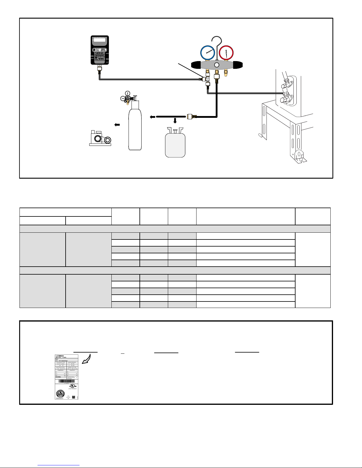
MANIFOLD GAUGE SET CONNECTIONS FOR LEAK TESTING, EVACUATION AND CHARGING
MICRON GAUGE
(REQUIRED FOR
EVACUATION
PROCEDURE ONLY)
VACUUM
PUMP
Temperature Condition ºF (ºC)
Indoor Outdoor
67 to 80
(19.4 to 26.7)
67 to 80
(19.4 to 26.7)
75 to 95
(23.9 to 35)
43 to 47
(6.1 to 8.3)
500
A34000 1/4 SAE TEE WITH
SWIVEL COUPLER
LOW
3
4
2
NITROGEN
HFC-410A
FIGURE 40
TABLE 12
LINE SET LENGTH AND ADDING REFRIGERANT
System
Size
(kBtu)
09K Turbo High 152 PSIG (1.05 MPa)
12K Turbo High 135 PSIG (0.93 MPa)
18K Turbo High 131 to 160 PSIG (0.9 to 1.1 MPa)
24K Turbo High 116 to 145 PSIG (0.8 to 1.0 MPa)
30k Turbo High 116 PSIG (0.8 MPa)
09K Turbo High 380 PSIG (2.62 MPa)
12K Turbo High 402 PSIG (2.77 MPa)
18K Turbo High 319 to 348 PSIG (2.2 to 2.4 MPa)
24K Turbo High 363 to 392 PSIG (2.5 to 2.7 MPa)
30K Turbo High 535 PSIG (3.69 MPa)
Indoor
Fan Mode
Cooling Mode
Heating Mode
Outdoor
Fan Mode
Standard Suction / Vapor Operating
HIGH
MANIFOLD GAUGE SET
Pressure Ranges
1
Line Set
Length
25 feet
(7.62 m)
25 feet
(7.62 m)
Note - Minimum line set length for all sizes is 10 feet (3 meters).
USING HFC-410A WEIGH-IN METHOD
Amount specified on
nameplate
Adjust amount. for variation in line set
length listed in table 12.
+
NOTE — The above nameplate is for illustration purposes only. Go to actual nameplate
on outdoor unit for charge information.
MS8C / MS8H (208-230V)
Total Charge
=
FIGURE 41
Page 24
Page 25
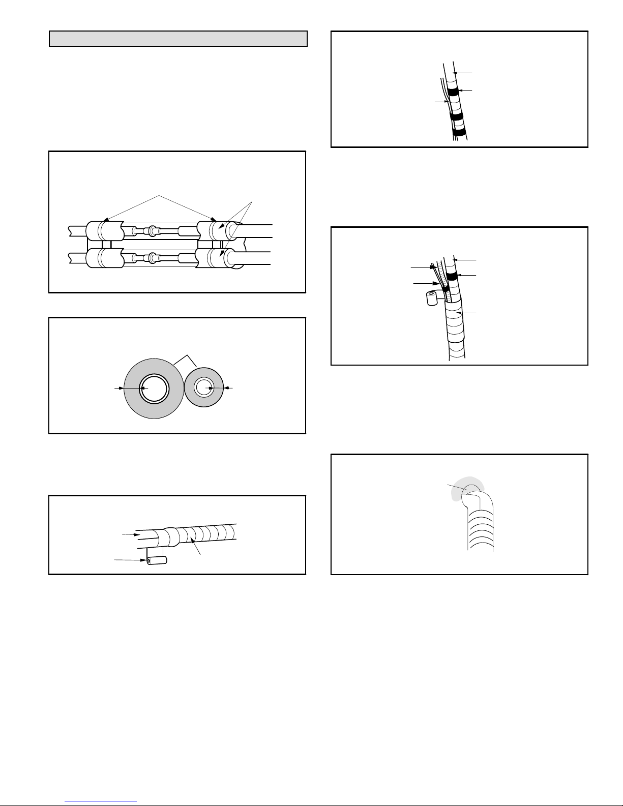
Wrapping Bundle
CONTROL WIRING BUNDLING
After system has been tested for leaks and proper
operation has been verified, use tape to bundle the control
wiring, line set and condensate line.
1. Wrap insulation material around the line set connection
between the indoor and outdoor units.
2. Insulate remaining sections of line set and condensate
line.
INSULATE AND TAPE LINE SET CONNECTION
PLASTIC WIRE TIES
TO INDOOR UNIT
INSULATION
MATERIAL
TO OUTDOOR UNIT
FIGURE 42
INSULATE LINE SET
INSULATION MATERIAL
INSULATE AND TAPE LINE
SET
CONTROL WIRING
BETWEEN INDOOR AND
OUTDOOR UNITS
WRAP WITH VINYL TAPE
(NARROW)
FIGURE 45
4. Tape the control wiring to the line set bundle (figure 45).
5. Start from the bottom of the bundle at the outdoor unit
and use tape to bundle the condensate line with the
control wiring and line set (figure 46).
UTILITY BUNDLE (CABLE, LINE SET AND
CONDENSATE DRAIN LINE)
CONDENSATE LINE
BETWEEN INDOOR
CABLE
AND OUTDOOR
UNITS
INSULATED LINE SET
WRAP WITH VINYL TAPE
(NARROW) (CABLE)
WRAP WITH VINYL TAPE
(WIDE)
MINIMUM
5/16” (8 MM)
LINE SET
MINIMUM
5/16” (8 MM)
FIGURE 43
3. Start from the bottom at the outdoor unit and use tape
to bundle the insulated line set together with tape
(figure 44).
TAPE LINE SET
LINE SET
WIDE VINYL
TAPE
WRAP WITH VINYL TAPE
FIGURE 44
FIGURE 46
1. Clamp bundle to wall. Use one clamp approximately
every 47” (1194 mm).
2. Apply sealant around the utility bundle on the outside
of the wall sleeve to prevent rain and outdoor air from
entering the room.
SEAL WALL SLEEVE AROUND BUNDLE
APPLY SEALANT HERE
BUNDLE
FIGURE 47
Page 25
Corp. 1244-L9
Page 26
3. An optional field-provided exterior wall channel may be
used in lieu of taping the utility bundle (see figure 48)
to protect the bundle from UV rays, weather, etc.
OPTIONAL EXTERIOR WALL CHANNEL
FIELD-PROVIDED PROTECTIVE
CHANNEL (UTILITY BUNDLE
INSIDE)
FIGURE 48
Maintenance
OUTDOOR UNIT
1. Ensure power is off before cleaning.
2. It may be necessary to wash the outdoor coil more
frequently if it is exposed to substances which are
corrosive or which block airflow across the coil (e.g.,
pet urine, cottonwood seeds, fertilizers, fluids that may
contain high levels of corrosive chemicals such as
salts).
3. Outdoor Coil (Sea Coast) — Moist air in ocean
locations can carry salt, which is corrosive to most
metal. Units that are located near the ocean require
frequent inspections and maintenance. These
inspections will determine the need to wash the unit
including the outdoor coil. Consult your installing
contractor for proper intervals/procedures for your
geographic area or service contract.
4. Outdoor unit fan motor is pre-lubricated and sealed. No
further lubrication is needed.
5. Visually inspect all connecting lines, joints and coils for
evidence of oil leaks.
6. Check all wiring for loose connections.
7. Check for correct voltage at unit (unit operating).
INDOOR UNIT
1. Clean or change filters.
2. Check all wiring for loose connections
3. Check for correct voltage at unit (blower operating).
4. Clean coil, if necessary.
5. Check connecting lines and coils for signs of oil leaks.
6. Check condensate line and clean, if necessary.
NOTE
— The filter must be in place and the front panel must
be closed any time the unit is in operation.
MS8C / MS8H (208-230V)
Page 26
Page 27
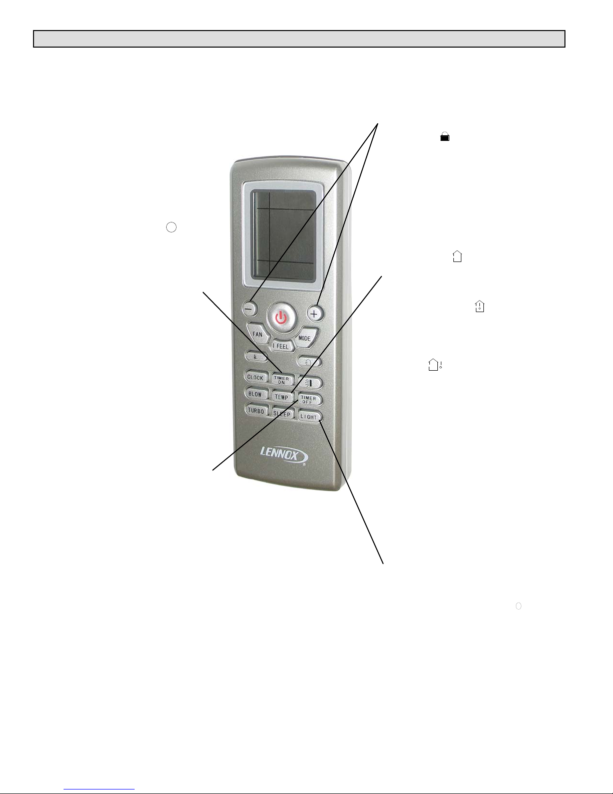
III. OPERATING THE WIRELESS REMOTE
Wireless Remote Functions
The wireless remote control provides system control to the homeowner at the touch of a
button. The indoor unit and remote control send information back and forth continuously.
The remote control must be placed on a table or other surface in direct line of sight with
the indoor unit infrared receiver. The remote control should not be placed in a drawer.
Make sure that there are no obstructions between the indoor unit receiver and the remote
control. Do not drop the control or spill liquid on the remote control.
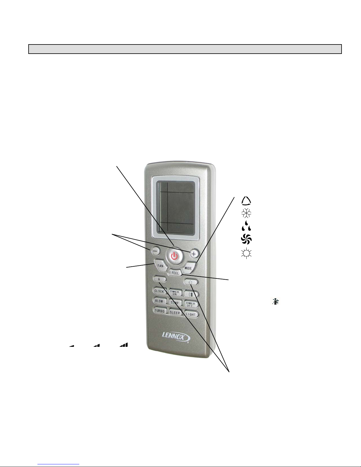
POWER button
Press this button once to turn
system on. Press again to
turn the system off. When the
POWER button is used to turn
the system OFF, it overrides the
Sleep Timer function (when it is
in use).
+/- buttons
Use plus (+) and minus (-) but
tons to adjust the temperature
setting up and down.
NOTE - The temperature cannot
be adjusted when the system is
in AUTO mode.
FAN button
Press this button to select fan
speed. AUTO fan is the default
setting. In AUTO fan mode, the
indoor fan speed is determined
by the indoor ambient tempera
ture. Press FAN button to step
through FAN setting selections:
AUTO, low speed, medium
speed and high speed.
Selected fan speed is shown at
the top of the remote control dis
play.
AUTO
Low Medium High
NOTE - The fan speed is not
adjustable during DEHUMIDIFI
CATION mode operation. The
low fan speed is necessary
to ensure optimal humidity
control.
MODE button
Press this button to select system
operating modes. AUTO mode is
the default setting. Press MODE
button again to select COOL mode,
again for DEHUMIDIFICATION
mode, again for FAN mode and
again for HEAT mode (heat pumps
only).
Selected mode is displayed on both
remote and indoor unit cover panel.
AUTO
COOL
DEHUMIDIFICATION
FAN
HEAT
I FEEL button
Press the I FEEL button to acti
vate the I FEEL feature. When
the I FEEL icon appears, tem
perature sensor in remote control
is used to initiate heating or cool
ing demands. Press
I FEEL button again to cancel
I FEEL feature and transfer room
temperature sensing back to
sensor in indoor unit.
UNUSED buttons
These buttons are not
functional in the MS8
system.
Page 27
Corp. 1244-L9
Page 28
Wireless Remote Functions (Continued)
SWITCH FROM °C TO °F
With system OFF, press MODE
and - buttons simultaneously to
switch from Centigrade to
Fahrenheit. Current selection
is displayed to the right of the
temperature display.
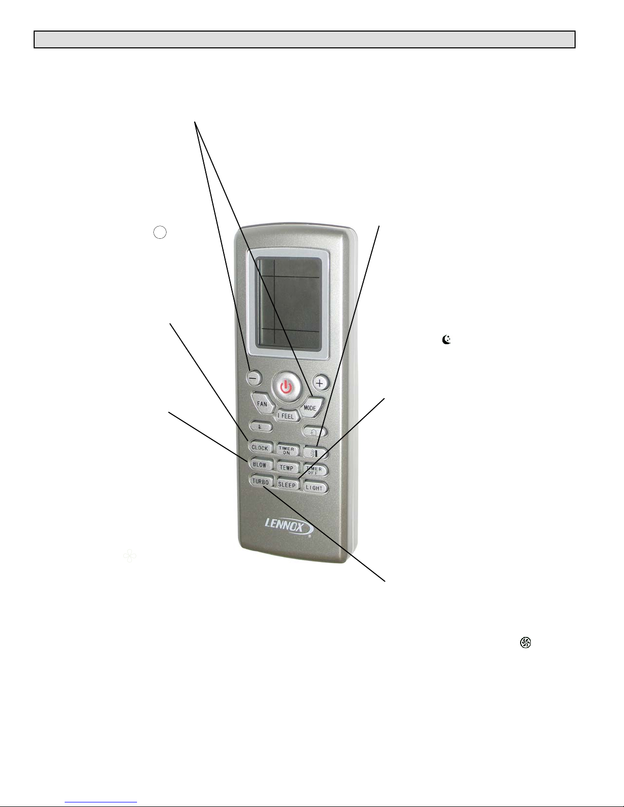
CLOCK button
Use the CLOCK button to adjust
the time displayed on the remote
control. Press the CLOCK button
once. The clock icon will
flash. Within 2 seconds, use the and + buttons to adjust the time
down or up in one-minute incre
ments. Press the button continu
ously to adjust the time in
10-minute increments. Press the
CLOCK button again when cor
rect time is displayed.
BLOW button
Use the BLOW button to
extend low speed blower
operation for 10 minutes
at the end of a cooling
demand.
The extended fan (BLOW)
operation ensures that excess
moisture is removed from the
indoor coil before the blower
shuts off.
Press the BLOW button once to
initiate extended blower opera
tion. Fan operation ends after 10
minutes.
The extended fan (BLOW)
operation icon is displayed
when the feature is turned on.
Extended fan (BLOW) operation
is available in cooling or dehu
midification modes; extended fan
(BLOW) operation is not avail
able in AUTO, heating or fan
mode.
LOUVER SETTING button
See page for complete details on
louver operation.
SLEEP button
Use the SLEEP button to initiate
or cancel the sleep function.
Press SLEEP button. When
sleep icon appears, press
TIMER OFF button and use and + buttons to set time for sys
tem shutdown. When desired
time is displayed, press TIMER
OFF button again. Press SLEEP
button to cancel sleep function.
In cooling mode, SLEEP function
increases temperature (+1.8°F
per hour) over a two-hour period
after the selected sleep time.
In heating mode, SLEEP function
decreases temperature (-1.8°F
per hour) over a two-hour period
after the selected sleep time.
NOTE - The sleep function is not
available in AUTO or FAN
modes.
TURBO button
Use the TURBO button to
initiate or cancel high-speed fan
operation to accelerate cooling
or heating of the ambient room
temperature. The turbo icon
is displayed when the function is
turned on.
MS8C / MS8H (208-230V)
Page 28
Page 29
Wireless Remote Functions (Continued)
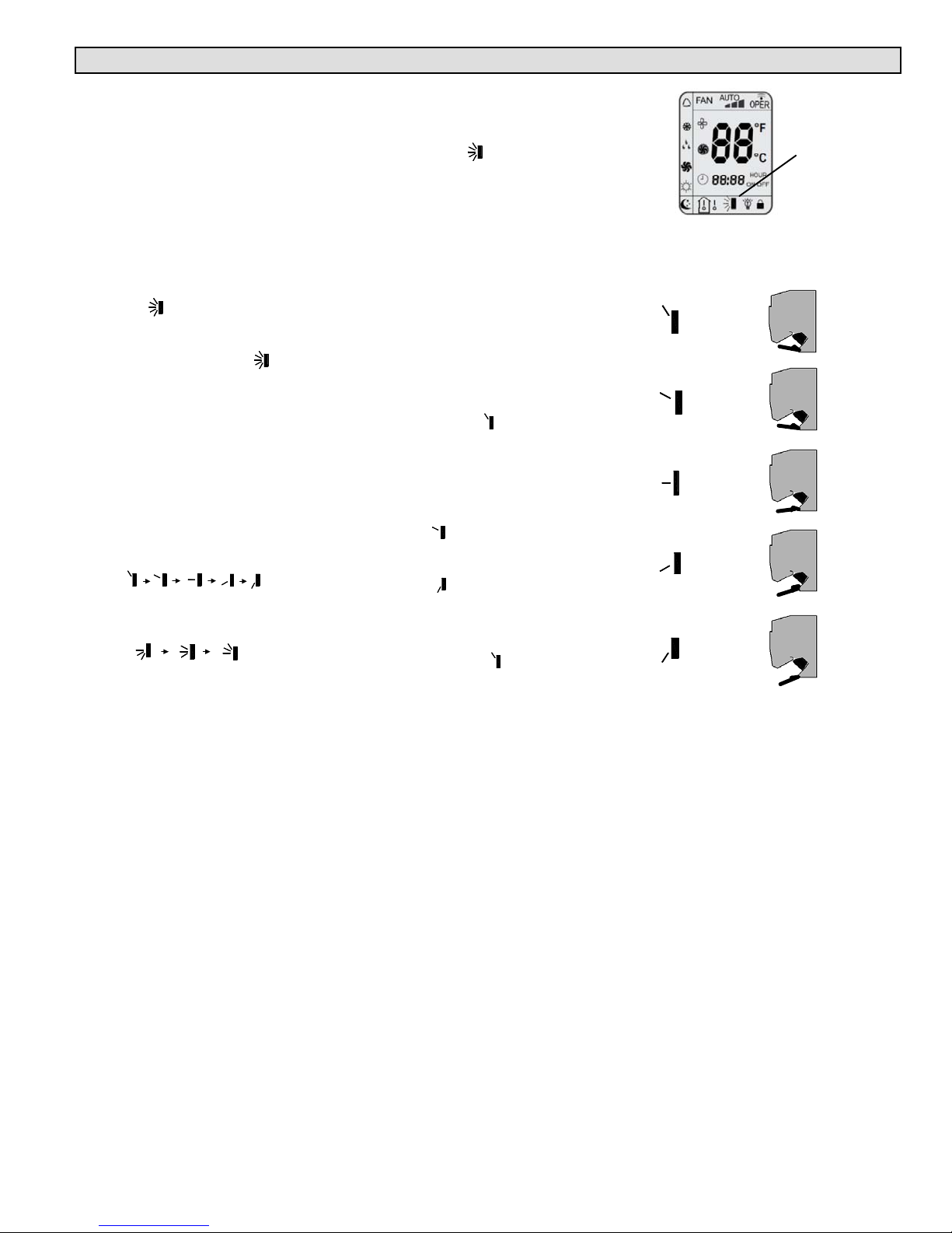
LOUVER SETTING button
Use the LOUVER SETTING
button to choose a preferred
setting for the indoor unit
directional louver.
NOTE - Actual louver
position is different than
what is shown on remote
icon. See comparison to
the right.
Press the LOUVER SETTING
button once to activate the
full-range oscillation mode
from top to bottom, then back
again. The louver icon will
appear in the lower section of
the screen.
Press the LOUVER SETTING
button again to turn the
feature OFF. The louver will
return to the default setting.
Press the LOUVER SETTING
button twice and continue to
press the button to scroll
through the five available
fixed positions
AND three other oscillating
positions.
To return the louver to the
default position, press the
LOUVER SETTING button
until the icon disappears.
Default Louver Positions
When the louver setting icon
is not displayed, the louver is
in the DEFAULT position.
When the remote control is
powered OFF, the default
position is fully closed.
When the remote control is set
so that the unit is in
COOLING, AUTO COOLING,
or DEHUMIDIFICATION
mode, the louver is in a fixed
upward position .
When the remote control is set
so that the unit is in HEAT or
AUTO HEATING mode and
the outdoor unit is OFF, the
louver is fixed in the second
position pointed upward. If
the outdoor unit is ON, the
louver is fixed in a downward
position .
When the remote is set for
continuous indoor fan to be
ON, the louver is fixed in an
upward position .
REMOTE
CONTROL ICON
POSITION
LOUVER
SETTING
ACTUAL
LOUVER
POSITION
o r a b o v e
ICON
Page 29
Corp. 1244-L9
Page 30
Wireless Remote Functions (Continued)
TIMER ON button
Use the TIMER ON button to ini
tiate or cancel a single timed-on
event. Use this feature to bring
the system on just before you re
turn home or just before you
wake in the morning.
Press the TIMER ON button
once. The clock icon
disappears and a time setting ap
pears with the word ON flashing
at the right. Use the - and + keys
to adjust the time setting to the
desired time for the system to
begin operation. Press the TIM
ER ON button again to
accept the setting. When suc
cessfully set, the word ON will
appear to the right of the current
time display. Press the TIMER
ON button again if you want to
cancel the timed-on event.
TIMER OFF button
Use the TIMER OFF button to
initiate or cancel a single timedoff event. Use this feature to turn
the system off just after you
leave the house or just after you
go to bed at night.
Use the same method
described above to set the de
sired time for the system to stop
operation. When successfully
set, the word OFF will appear to
the right of the current time dis
play. Press the TIMER OFF but
ton again if you want to cancel
the timed-off event.
REMOTE LOCK
Press - and + buttons simulta
neously to either lock or unlock
the remote control buttons. When
locked, the icon is
displayed.
TEMP button
Use the TEMP button to change
the temperature display shown
on the remote control. When ini
tially powered on, the current
temperature setting is displayed,
along with the icon.
Press the TEMP button once
to alter the display to show the
current indoor ambient tempera
ture, along with the icon. The
indoor temperature sensor is in
the indoor unit.
Press the TEMP button again to
display the outdoor ambient tem
perature icon. The outdoor
ambient temperature display is
not available on this system.
On occasion, the remote control
will display the temperature that
was not selected (indoor ambient
temperature or setting tempera
ture). The selected temperature
will return to the display screen
after 5 seconds.
NOTE - The TEMP button can
also be used to temporarily dis
play the indoor ambient tempera
ture on the indoor unit display
panel.
LIGHT button
Use the LIGHT button to turn the
indoor unit display light on and
off. When the light is on, the
icon appears on the remote con
trol.
MS8C / MS8H (208-230V)
Page 30
Page 31

System Start Up Using Wireless Remote
General Operation
1 - Press POWER button once to turn system on.
2 - Press MODE button until desired operating
mode icon is displayed.
NOTE - When AUTO mode is selected, the
temperature setting is not displayed on the
remote control. The - and + buttons cannot be
used to make temperature setting selections.
3 - Press - or + buttons until desired temperature
setting is displayed.
NOTE - Skip this step in AUTO mode.
4 - Press FAN button until desired fan speed icon
is displayed.
NOTE - Fan speed will be set to low if
DEHUMIDIFICATION mode has been selected.
5 - Press OSCILLATE button. Indoor unit
directional louver will open and begin to
oscillate. If a single setting is preferred, press
button again when louver is in the desired
position. Louver will remain in desired position
until system is powered off.
Special Functions
6 - Press SLEEP button to initiate sleep function.
Then press TIMER OFF button to set timed
off.
7 - Use TIMER ON and TIMER OFF buttons to
schedule desired timed on and off settings.
8 - Use LIGHT button to set display light on or off.
9 - Use BLOW button to turn on and off extended
fan operation feature.
1
4
9
10
6
2
11
3
5
7
8
10-Use TURBO button to turn accelerated fan
speed on or off.
11- Use I FEEL button to use temperature sensor
in remote control to initiate cooling and heat
ing demands.
Page 31
Corp. 1244-L9
Page 32

Remote Control Batteries
The wireless remote control requires two AAA, 1.5V batteries.
DO NOT attempt to use any other type of battery.
Follow the steps below and in the illustrations to replace the
batteries when necessary.
1 - Remove screw that secures the battery access panel to
the remote. Place thumb on at the top of the battery
access panel on the back of the remote control. Slide
the panel in the direction of the arrow.
2 - Remove the existing AAA, 1.5V batteries.
3 - Replace batteries with fully charged AAA, 1.5V batteries.
NOTE - Pay attention to proper polarity of batteries. Remote
control will not operate if batteries are improperly installed.
4 - Reposition battery access panel and slide forward until
panel snaps into locked position. Reinsert screw.
SCREW
SCREW
IMPORTANT !
D If wireless remote will not be used for a long period of
time, remove batteries to avoid damage to the control.
D To verify that the remote control is transmitting com
mands to the indoor unit, press any command key and
a wireless icon will appear in the upper right-hand
corner of the remote control display.
D When being used in the I FEEL mode, t
he remote con
trol must be placed on a table or other surface in direct
line of sight with the indoor unit infrared receiver. The
control should not be placed in a drawer. Make sure that
there are no obstructions between the indoor unit receiv
er and the remote control.
D Remote should remain within its receiving range to ensure proper system control.
Control should be kept at least 3 feet (914mm) away from other electrical appliances
(televisions, stereos, etc.) to prevent signal interference.
D If remote control operation becomes erratic, remove batteries. Wait 30 seconds and
reinsert batteries. If proper remote operation is not restored, replace batteries.
MS8C / MS8H (208-230V)
Page 32
Page 33

Auto ON Switch
If the remote control is lost or damaged, or if
charged AAA, 1.5V batteries are not available,
the Auto ON switch can be used to turn the
system on or off.
The Auto ON switch is located behind the cov
er panel on the indoor unit. Lift the front panel
and press the ON button once briefly to start
the system. To stop emergency operation,
push the ON button again.
IMPORTANT !
The Auto ON button initiates operation in
the AUTO mode. The temperature and fan
speed are not adjustable in the AUTO
mode.
AUTO Switch
(Recessed)
AUTO
PENCIL OR OTHER
NON-METALLIC OBJECT
AUTO Switch
(Not Recessed)
PRESS
WITH
FINGER
AUTO BUTTON
Page 33
Corp. 1244-L9
Page 34

Homeowner Maintenance
WARNING!
Turn off all power to unit at system disconnect switch (at the
outdoor unit) or circuit breaker before performing any main
tenance procedures! Failure to follow this warning could lead
to personal injury or death.
Coil fins are very sharp! Take care not to touch the fins in or
der to avoid injury.
Indoor Unit Filters
The indoor unit filter should be cleaned every three months, or
more frequently, if necessary.
Follow the steps below and in the illustrations to clean the filters.
1 - Pivot indoor unit front panel out and up to access filters.
2 - Gently pull each filter outward, then down to remove the filters
from the unit
3 - Use a vacuum cleaner to remove dust and dirt from each filter
or wash the filters with warm water and a mild detergent.
Rinse filters thoroughly with clean water and set aside to air
dry.
CAUTION!
Do not use hot water to clean the filters. Exposure to wa
ter temperatures above 113°F (45°C) will damage filter
media and frame.
4 - Reinsert clean, dry filters and close unit front panel. Restore
power to unit.
1
2
3
4
Indoor Unit
Check to make sure that there are no objects on top of unit or around unit that may be obstructing air
flow. Check to make sure that indoor unit and wall bracket are secure and have not been damaged.
Use a clean, dry cloth to gently remove dust from the outer surface of the indoor unit. The cloth may
be slightly dampened with warm water, if necessary. Do not use soap or other cleaners.
CAUTION!
Hot water, soaps or other cleaning agents may damage indoor unit cabinet or display panel.
Do not use hot water (above 113°F [45°C]). Cloth must be damp only (NEVER WET) to avoid
damage to display. Do not use soap or other cleaning agents (window cleaner, abrasive
cleansers, etc.) to clean the indoor unit cabinet.
Outdoor Unit
Check to make sure that there are no objects on top of unit or around unit that may be obstructing air
flow. If the outdoor unit is installed on a wall bracket, make sure that bracket is secure and has not
been damaged. Use a clean, slightly dampened cloth to gently remove dust from the outer surface of
the outdoor unit. Do not use soap or other cleaners and DO NOT spray water into unit.
WARNING!
SHOCK HAZARD! DO NOT SPRAY water into outdoor unit. Failure to follow this warning could
lead to electrical shock, resulting in personal injury or death.
Lennox recommends annual inspection by a licensed professional service technician, or equiva
lent.
MS8C / MS8H (208-230V)
Page 34
Page 35

IV. SYSTEM OPERATION AND SERVICE
SYSTEM OPERATIONAL MODES
Air conditioner systems have four modes of operation. Heat pumps have five operational modes. These modes are:
* Auto
* Cooling
* Dehumidification
* Fan
* Heat (HP model only)
AUTO MODE
Auto Mode - Non-adjustable indoor temperature set points are 68F°and 77°F (20°C and 25°C)
NOTE — Reversing valve is de-energized in cooling mode and energized in heating mode.
AUTO MODE
Delays that normally protect the compressor are disabled during defrost cycles:
1. Minimum three (3) minute compressor time delay between operating cycles.
2. Minimum six (6) minute compressor run time between operating cycles.
If room ambient temperature is equal to or greater than 77°F (25°C), the unit cycles cooling ON. When the room ambient
temperature is equal to or less than 77°F (25°C) minus 3.6°F (2°C), the compressor will cycle OFF, the outdoor fan will cycle
OFF 60 seconds later. The indoor fan will run continuously at a preset speed until system has a heating demand or Auto Mode
is switched OFF.
If room temperature is equal to or less than 64°F (18°C) plus 3.6°F (2 C), the heating will cycle ON when room temperature is
equal to or greater than 64°F (18°C) plus 9.0°F (5°C), the compressor will cycle OFF. The outdoor fan will cycle OFF 60
seconds later. The indoor fan will cycle OFF after 60 seconds on low speed.
FIGURE 49
Protective Functions
Auto — Cool
Auto — Heat
Page 35
Corp. 1244-L9
Page 36

COOLING MODE (I FEEL MODE OFF)
Cool Mode - Indoor temperature set point range is 61°F and 86°F (16°C and 30°C)
NOTE — Reversing valve is de-energized in cooling mode.
COOLING MODE
FIGURE 50
Protective Functions
Delays that normally protect the compressor are disabled during defrost cycles:
1. Minimum three (3) minute compressor time delay between operating cycles.
2. Minimum six (6) minute compressor run time between operating cycles.
Cool ON
If room ambient temperature is equal to or greater than the remote control set point, the unit cycles cooling ON.
Cool OFF
If room temperature is equal to or less than remote control set point minus 3.6ºF (2ºC), the compressor will cycle OFF. The
outdoor fan will cycle OFF 30 seconds later. The indoor fan will continue to operate.
Indoor Fan Operation - Cooling
1. The indoor fan runs continuously.
2. The fan speed is determined by the difference between the room ambient temperature and the remote set point
temperature.
INDOOR FAN OPERATION - COOLING
MS8C / MS8H (208-230V)
FIGURE 51
Page 36
Page 37

COOLING MODE (I FEEL MODE ON)
Cool Mode - Indoor temperature set point range is 61°F and 86°F (16°C and 30°C)
NOTE — Reversing valve is de-energized in cooling mode.
COOLING MODE
FIGURE 52
Protective Functions
Delays that normally protect the compressor are disabled during defrost cycles:
1. Minimum three (3) minute compressor time delay between operating cycles.
2. Minimum six (6) minute compressor run time between operating cycles.
I FEEL Mode
The indoor unit will cycle the system to maintain the remote control temperature setting. The remote control will send its
temperature setting to the indoor unit every 10 minutes. If the indoor unit does not receive the remote control signal after 11
minutes, the system will revert back to maintaining the setting of the return air sensor. If main power is interrupted to system,
I FEEL mode will need to be reset by turning the I FEEL mode OFF and ON.
NOTE - For I FEEL mode to work, infrared eye on remote must be aimed at indoor front panel.
Cool ON
If room ambient temperature is equal to or greater 1.8°F (1°C) than the remote control setpoint, the unit cycles cooling ON.
Cool OFF
If room temperature is equal to or less than remote control setpoint minus 1.8°F (1°C), the compressor will cycle OFF. The
outdoor fan will cycle OFF 30 seconds later. The indoor fan will continue to operate.
Indoor Fan Operation - Cooling
1. The indoor fan runs continuously.
2. The fan speed is determined by the difference between the room ambient temperature and the remote set point
temperature.
INDOOR FAN OPERATION - COOLING
FIGURE 53
Page 37
Corp. 1244-L9
Page 38

DEHUMIDIFICATION MODE (I FEEL MODE OFF)
Dehumidification Mode - Indoor temperature set point range is 61°and 86°F (16°C and 30°C)
DEHUMIDIFICATION MODE
FIGURE 54
Protective Functions
Delays that normally protect the compressor are disabled during defrost cycles:
1. Minimum three (3) minute compressor time delay between operating cycles.
2. Minimum six (6) minute compressor run time between operating cycles.
Cool ON
If room ambient temperature is equal to or greater than the remote control set point, the unit cycles cooling ON.
Cool OFF
If room temperature is equal to or less than remote control set point minus 3.6ºF (2ºC), the compressor will cycle OFF. The
outdoor fan will cycle OFF 30 seconds later. The indoor fan will continue to operate.
Indoor Fan Operation - Dehumidification
The indoor fan runs continuously at low speed.
FAN MODE
The indoor fan will run at a preset speed and the compressor, outdoor fan and reversing valve (heat pump only) will be off.
MS8C / MS8H (208-230V)
Page 38
Page 39

DEHUMIDIFICATION MODE (I FEEL MODE ON)
Dehumidification Mode - Indoor temperature set point range is 61°F and 86°F (16°C and 30°C)
DEHUMIDIFICATION MODE
FIGURE 55
Protective Functions
Delays that normally protect the compressor are disabled during defrost cycles:
1. Minimum three (3) minute compressor time delay between operating cycles.
2. Minimum six (6) minute compressor run time between operating cycles.
Cool ON
If room ambient temperature is equal to or greater than the remote control set point, the unit cycles cooling ON.
Cool OFF
If room temperature is equal to or less than remote control set point minus 3.6ºF (2ºC), the compressor will cycle OFF. The
outdoor fan will cycle OFF 30 seconds later. The indoor fan will continue to operate.
Indoor Fan Operation - Dehumidification
The indoor fan runs continuously at low speed.
FAN MODE
The indoor fan will run at a preset speed and the compressor, outdoor fan and reversing valve (heat pump only) will be off.
Page 39
Corp. 1244-L9
Page 40

HEAT MODE (I FEEL MODE OFF)
Heat Mode - Indoor temperature set point range is 61°F and 86°F (16°C and 30°C)
NOTE — Reversing valve is energized in heating mode.
HEATING MODE
FIGURE 56
Protective Functions
Delays that normally protect the compressor are disabled during defrost cycles:
1. Minimum three (3) minute compressor time delay between operating cycles.
2. Minimum six (6) minute compressor run time between operating cycles.
Heat ON
If room ambient temperature is equal to or less than the remote control set point plus 3.6ºF (2ºC), the unit cycles heat ON. If it
has been three (3) minutes since the last heat demand, the compressor and outdoor fan will cycle ON. The indoor fan will
operate according to the cold blow prevention function.
Heat OFF
If room temperature is equal to or greater than remote control set point plus 9ºF (5ºC), the compressor will cycle OFF. The
outdoor fan will cycle OFF 30 seconds later. The indoor fan will operate for 60 seconds after heat cycles OFF.
Indoor Fan Operation - Heating
The fan speed is determined by the difference between the room ambient temperature and the remote set point temperature.
Cold Blow Prevention
The system prevents cold air from blowing into space during heating operation. After three (3) minute time delay, one of the
following indoor fan cycles will occur:
* If the indoor ambient temperature is greater than 75ºF (24ºC): If the coil temperature is equal to or greater than 104ºF
(40ºC) the indoor fan will run at low speed for 1 to 2 minutes. If during that time the coil temperature rises above 106ºF
(42ºC), the indoor fan will ramp to a preprogrammed heat speed for those conditions.
* If the indoor ambient temperature is less than 75ºF (24ºC): If the coil temperature is equal to or greater than 106ºF (42ºC)
the indoor fan will run at low speed and within one minute, the indoor fan will ramp to preprogrammed heat speed for
those conditions.
Reversing Valve Operation
The reversing valve is energized in heating and will stay energized for two minutes after the compressor is de-energized. The
reversing valve is energized 2 seconds before the compressor is energized.
MS8C / MS8H (208-230V)
Page 40
Page 41

HEAT MODE (I FEEL MODE ON)
Heat Mode - Indoor temperature set point range is 61°F and 86°F (16°C and 30°C)
NOTE — Reversing valve is energized in heating mode.
HEATING MODE
FIGURE 57
Protective Functions
Delays that normally protect the compressor are disabled during defrost cycles:
1. Minimum three (3) minute compressor time delay between operating cycles.
2. Minimum six (6) minute compressor run time between operating cycles.
Heat ON
If room ambient temperature is equal to or less than the remote control setpoint - 1.8°F (1°C) the unit cycles heating ON. If it
has been 3 minutes since the last heating demand, the compressor and outdoor fan motor will cycle ON. The indoor fan will
operate according to the Cold Blow Prevention function.
Heat OFF
If room temperature is equal to or greater than remote control setpoint + 1.8°F (1 °C ), the compressor will cycle OFF. The
outdoor fan will cycle OFF 30 seconds later. The indoor fan will operate for 60 seconds after heating cycles OFF.
Indoor Fan Operation - Heating
The fan speed is determined by the difference between the room ambient temperature and the remote set point temperature.
Cold Blow Prevention
The system prevents cold air from blowing into space during heating operation. After three (3) minute time delay, one of the
following indoor fan cycles will occur:
* If the indoor ambient temperature is greater than 75ºF (24ºC): If the coil temperature is equal to or greater than 104ºF
(40ºC) the indoor fan will run at low speed for 1 to 2 minutes. If during that time the coil temperature rises above 106ºF
(42ºC), the indoor fan will ramp to a preprogrammed heat speed for those conditions.
* If the indoor ambient temperature is less than 75ºF (24ºC): If the coil temperature is equal to or greater than 106ºF (42ºC)
the indoor fan will run at low speed and within one minute, the indoor fan will ramp to preprogrammed heat speed for
those conditions.
Reversing Valve Operation
The reversing valve is energized in heating and will stay energized for 2 minutes after the compressor is de-energized. The
reversing valve is energized 2 seconds before the compressor is energized.
Page 41
Corp. 1244-L9
Page 42

DEFROST MODE (HEAT PUMP ONLY)
The front panel indicator will display an H1 code when the system is in defrost. The system will perform as indicated in the
figure 58.
DEFROST MODE
FIGURE 58
Protective Functions
Delays that normally protect the compressor are disabled during defrost cycles:
1. There is no three (3) minute minimum compressor time off delay between operating cycles.
2. There is no six (6) minute minimum compressor operating cycles.
Defrost Initiation
Defrost is controlled by the microprocessor and will be initiated when:
* System is in heating mode,
* System has been running for at least six (6) minutes, or
* Successive heating operations of more than 45 minutes or accumulated heating time more than 90 minutes.
* One of the conditions listed under defrost termination that last longer than three (3) minutes.
Defrost Termination
Defrost is controlled by the microprocessor and will be terminated when:
* Outdoor coil temperature goes above 55ºF (13ºC) +
5ºF (+ 3ºC)
* Defrost time is a maximum of ten (10) minutes.
Cold Blow Prevention
The system prevents cold air from blowing into space during heating operation. After three (3) minute time delay, one of the
following indoor fan cycles will occur:
* If the indoor ambient temperature is greater than 75ºF (24ºC): If the coil temperature is equal to or greater than 104ºF
(40ºC) the indoor fan will run at low speed for 1 to 2 minutes. If during that time the coil temperature rises above 106ºF
(42ºC), the indoor fan will ramp to a preprogrammed heat speed for those conditions.
* If the indoor ambient temperature is less than 75ºF (24ºC): If the coil temperature is equal to or greater than 106ºF (42ºC)
the indoor fan will run at low speed and within one minute, the indoor fan will ramp to preprogrammed heat speed for
those conditions.
Defrost Test Function
When the unit is in Heat mode and set temperature is 61 F (16 C), press ”+, -, +, -, +, -” successively for 5 seconds. The indoor
and outdoor unit will enter defrost test function.
MS8C / MS8H (208-230V)
Page 42
Page 43

SYSTEM FUNCTIONS
These systems have several functions which are addressed in this section. These functions are:
* Sleep
* Turbo
* Cold Blow Prevention (Heat Pumps Only)
SLEEP
Cooling or Dehumidification — Sleep Function
When sleep function has been set properly , the setpoint will be increased by 1.8°F (1°C) after the sleep function has run for 1
hour, will be increased by another 1.8°F (1°C) after 2 hours and increased by another 1.8°F (1°C) after 3 hours. The setpoint
will be increased by 5.4°F (3°C) total in three hours. No further temperature adjustments will be made for the remainder of the
sleep function.
Heating — Sleep Function
When sleep function has been set properly , the setpoint will be decreased by 1.8°F (1°C) after the sleep function has run for 1
hour, will be increased by another 1.8°F (1°C) after 2 hours and increased by another 1.8°F (1°C) after 3 hours. The setpoint
will be decreased by 5.4°F (3°C) total in three hours. No further temperature adjustments will be made for the remainder of
the sleep function.
SLEEP FUNCTION
TURBO
When turbo function is activated, the indoor fan speed and compressor frequency (speed) is increased to maximize the
delivery of cooled or heated air to the space.
Operational Mode Maximum Fan Speed Compressor Speed
Cool Maximum Speed Operating frequency + 10HZ
Dehumidification No Change No Change
Heat Maximum Speed Operating frequency + 10HZ
Fan No Change No Change
Auto No Change No Change
FIGURE 59
TABLE 13
TURBO FUNCTION
Page 43
Corp. 1244-L9
Page 44

COLD BLOW PREVENTION
This function prevents cold air from blowing into space in heating mode. After a three (3) minute time delay, one of the
following two indoor fan cycles occurs:
1. When the following conditions are met:
A. Indoor ambient temperature is greater than 75°F (24°C).
B. Coil temperature is equal to or greater than 104°F (40°C).
The indoor fan will run at low-speed for one to two minutes. If during that time the coil temperature rises above 106°F
(42°C) the indoor fan will ramp to a pre-programmed heat speed for those conditions.
2. When the following conditions are met:
A. Indoor ambient temperature is equal to or less than 75°F (24°C)
B. Coil temperature is equal to or greater than 106°F (42°C)
The indoor fan will run at low-speed, and within one minute, the indoor fan will ramp to a preprogrammed heat speed for
those conditions.
SYSTEM PROTECTION FEATURES
COMPRESSOR PROTECTION
In order to protect the compressor, there is a 3-minute delay after the unit shuts off. The delay occurs even during a call for
heating or cooling.
INDOOR COIL FREEZE PROTECTION
When the unit is running in the COOL or DEHUMIDIFICATION mode, the indoor coil can freeze due to any of the following:
* Low system charge
* Reduced indoor airflow (restricted filter)
* Restricted refrigerant flow
* Low ambient temperature (outdoor)
* Low indoor system load
The indoor coil sensor monitors the coil temperature continuously. If the coil temperature drops below 30.2°F (-1°C), the
compressor and the outdoor fan (30 seconds later) will be turned OFF. When the coil temperature rises above 42.8°F (6°C)
and the compressor has been off for 3 minutes, the compressor and outdoor fan will cycle ON.
INDOOR COIL FREEZE PROTECTION
FIGURE 60
Indoor Fan Operation
When compressor is cycled ”OFF”, the indoor fan will continue to run at a preset speed.
MS8C / MS8H (208-230V)
Page 44
Page 45

INTELLIGENT POWER MODULE (IPM) PROTECTION (H5)
The IPM module, which is an integrated part of the outdoor control, protects the system from the following conditions:
* High ambient temperatures
* Loss of cooling to the heat sink
* Low voltage
* Loose heat sink to control board
An inverter drive (VFD) works by taking AC mains (single or three phase) and first rectifying it into DC. The DC is usually
smoothed with capacitors and often a DC choke before it is connected to a network of power transistors to turn it into three
phases for the motor.
The network of power transistors of a small Inverter drive is actually one intelligent power module or inverter power module
(IPM) and includes its own basic control circuits and protection from overheating and low voltage conditions.
The IPM inverts the DC into AC, hence the term inverter. The control method is known as for pulse width modulation (PWM).
This means the DC is switched on and off very quickly (chopped) by the transistor switches.
POWER FACTOR CORRECTION (PFC) PROTECTION (HC)
The PFC module which is an integrated part of the outdoor control will monitor the DC bus for high, low and abnormal voltage
conditions. If any of these conditions are detected the PFC function and compressor will stopped. The appropriate error code
will be displayed on the indoor or outdoor units or both. Once the detected condition is corrected, the system will resume
normal operations after the minimum 3-minute compressor delay is met. In the case of either an abnormal condition or a high
/ low voltage condition that has occurred three consecutive times, the system will need to be manually powered off (outdoor
unit disconnect or main breaker panel) and back on to continue operation.
NOTE — HC for example is an error code for a PFC module failure. Codes that are generated by the PFC module when
monitor voltage conditions are for example H4, U3, PL, etc.
COMPRESSOR OVER-CURRENT PROTECTION (P5)
The compressor current is continuously monitored. Based on the current draw (amps) the microprocessor will signal the
compressor to increase, maintain drop or cycle OFF the compressor. Over current condition can result from any of the
following:
* High outdoor ambient temperatures
* Locked rotor on the compressor
* Outdoor air restriction or blockage
* Restriction or blockage in refrigeration system
COMPRESSOR OVER-LOAD PROTECTION (OVC-COM) (H3)
If temperature detected by the overload sensor exceeds 239ºF (115ºC), the compressor will stop. The outdoor fan will stop
after a delay of 30 seconds. Once the compressor temperature drops below 204ºF (95ºC), the compressor overload
protection feature will reset and the system will resume normal operations.
OUTDOOR COIL HIGH TEMPERATURE PROTECTION (FA)
Outdoor coil for air conditioning operation and indoor coil for heating operation (Heat pump only). When the coil
temperature (outdoor coil for air conditioning and indoor coil for heating) drops below 124°F ( 51°C) and the compressor has
been OFF for more than 3 minutes, the system will resume normal operation. The coil sensor (outdoor coil sensor for air
conditioning and indoor coil sensor for heating) is continuously monitoring the coil temperature and communicates this to the
microprocessor. The microprocessor takes these measurements and changes the frequency of the compressor to meet the
system load. If the coil temperature increases into the ranges noted in the above chart, the microprocessor will adjust the
frequency or cycle the compressor OFF.
Indoor Fan Operation
When compressor is cycled OFF, the indoor fan will continue to run at a preset speed in air conditioning or in heating it will
cycle OFF 60 seconds after compressor.
Page 45
Corp. 1244-L9
Page 46

OUTDOOR COIL HIGH TEMPERATURE PROTECTION
FIGURE 61
COMMUNICATION FAULT (E6)
If either the indoor or outdoor controls are unable to communicate with each other for a minimum of three minutes, the system
will stop and an error code is displayed on the indoor unit.
OUTDOOR UNIT CONTROL PROTECTION
When excessive temperature is sensed at the outdoor unit control, the compressor will stop. The compressor anti-short cycle
routine will be implemented and the compressor will not resume operation until the 3-minute time period has ended.
OTHER FUNCTIONS
SYSTEM REFRIGERANT RECOVERY FUNCTION (PUMP DOWN SYSTEM REFRIGERANT INTO OUTDOOR UNIT)
Enter Refrigerant Recovery Mode
1. Set all zone remote controls at 61ºF (16ºC) in the cooling mode.
2. Within five (5) minutes of system cooling operation, press remote control LIGHT button three (3) times consecutively
within three (3) seconds.
3. The system will enter refrigerant recover mode. Indoor display will indicate Fo, indoor fan will run on high speed and
the louver position will be adjusted.
Exit Refrigerant Recovery Mode
1. If remote control cooling mode setting is changed or refrigerant recovery mode has lasted longer than 25 minutes the
system will exit this mode.
2. The indoor fan will run at the last setting before the system was placed in refrigerant recovery mode.
INDOOR MODE CONFLICT PROTECTION (E7)
When different modes of operation are being called by various indoor units:
1. Basic Mode: The first indoor unit to make a call for cooling or heating will established what is considered basic mode
for the outdoor unit operation. Cooling mode is a conflict with heating mode. Indoor units in conflict with first zone call
will display E7 on the front panel.
2. When the outdoor unit's basic mode is set to heating, then any request for fan mode at a indoor unit is made will be
ignored. Even when the first unit to operate is in fan mode, if any other indoor unit makes a call for heating, the basic
mode will be for heating. Fan mode is a conflict with heating mode.
MS8C / MS8H (208-230V)
Page 46
Page 47

TEMPERATURE SENSORS (LOCATION, FUNCTION AND TROUBLESHOOTING)
Refer to tables 15, 16 and 17 for sensor resistance valves and figure 63 for location of sensors.
INDOOR UNIT
1. Indoor Air Temperature Sensor (RT1): This sensor measures the return air temperature coming into the indoor coil
and sends this information to the indoor and outdoor controls.
2. Indoor Coil Temperature Sensor (RT2): This sensor is located on one of the copper tubes of the indoor coil. This sensor
is used to:
S Control the electronic expansion valve (EEV) in cooling mode;
S Prevent freezing. During cooling operation, if the temperature drops abnormally, the compressor speed is
decreased. If the temperature continues to fall, the compressor will be cycled OFF;
S Terminate defrost cycle.
OUTDOOR UNIT
1. Outdoor Coil Temperature Sensor (RT3): This sensor is located on one of the copper tubes of the outdoor coil. This
sensor is used to:
S Control the electronic expansion valve (EEV) in heating mode;
S Protect the system from high temperatures during cooling mode;
S Terminate defrost cycle.
2. Outdoor Air Temperature Sensor (RT4): This sensor measures the outdoor air temperature coming into the outdoor
coil and sends this information to the outdoor controls.
3. Discharge Line Temperature Sensor (RT5): This sensor is used to monitor the discharge line temperature. If the
temperature of the discharge pipe rises abnormally, the compressor speed is decreased. If the temperature continues
to rise, the compressor will be cycled OFF.
Page 47
Corp. 1244-L9
Page 48

DISCHARGE LINE TEMPERATURE SENSOR (RT5)
High compressor discharge temperature can result from either of the following conditions:
* Low refrigerant charge
* Restricted refrigerant flow
When the discharge line temperature drops below 194°F (90°C) and the compressor has been OFF for more than 3 minutes,
the system will resume normal operation.The discharge line sensor continuously monitors the discharge temperature and
communicates this to the microprocessor. The microprocessor takes these measurements and changes the frequency of the
compressor to meet the system load. If the discharge temperature increases to the ranges noted in the above chart, the
microprocessor will adjust the frequency or cycle the compressor OFF (table 14).
DISCHARGE LINE TEMPERATURE PROTECTION SEQUENCE (RT5)
FIGURE 62
TABLE 14
MONITORING OF OUTDOOR DISCHARGE (RT5) LINE TEMPERATURE
Condition Action
If outdoor discharge line temperature is greater than 208.ºF (98ºC) Change in compressor speed is not allowed.
If outdoor discharge line temperature is greater than 217ºF (103ºC) Compressor will run at reduced speed.
If outdoor discharge line temperature is greater than 230ºF (110ºC) Compressor will stop.
If outdoor discharge line temperature is less than 194ºF (90ºC)
After anti-short cycle (3 minutes) delay, the compressor and outdoor fan
will resume operation.
Indoor Fan Operation
When compressor is cycled ”OFF”, the indoor fan will continue to run at a preset speed in air conditioning or in heating it will
cycle ”OFF” 60 seconds after compressor.
TEMPERATURE SENSOR FAULTS
Refer to the error code tables for details concerning fault conditions and equipment behavior.
TESTING TEMPERATURE SENSOR RESISTANCES
Sensors are connected to the indoor and outdoor controls through field-replaceable harnesses. These sensors provide
indoor ambient air (RT1), outdoor ambient air (RT4), indoor coil (RT2), outdoor coil (RT3) and outdoor discharge line (RT5)
temperatures to the indoor and outdoor controls to identify fault conditions. As the temperature changes, the resistance
across these sensor changes. Tables 15 through 17 indicates how the resistance varies as the temperature changes for all
reference temperature sensors.
MS8C / MS8H (208-230V)
Page 48
Page 49

TABLE 15
INDOOR AND OUTDOOR AMBIENT SENSOR RESISTANCE VALUES (15K) — ºF (ºC)
Temp.(°F) Resistance(kΩ) Temp.(°F) Resistance(kΩ) Temp.(°F) Resistance(kΩ) Temp.(°F) Resistance(kΩ)
-2.2 138.1 68 18.75 138.2 3.848 208.4 1.071
-0.4 128.6 69.8 17.93 140 3.711 210.2 1.039
1.4 121.6 71.6 17.14 141.8 3.579 212 1.009
3.2 11 5 73.4 16.39 143.6 3.454 213.8 0.98
5 108.7 75.2 15.68 145.4 3.333 215.6 0.952
6.8 102.9 77 15 147.2 3.217 217.4 0.925
8.6 97.4 78.8 14.36 149 3.105 219.2 0.898
10.4 92.22 80.6 13.74 150.8 2.998 221 0.873
12.2 87.35 82.4 13.16 152.6 2.896 222.8 0.848
14 82.75 84.2 12.6 154.4 2.797 224.6 0.825
15.8 78.43 86 12.07 156.2 2.702 226.4 0.802
17.6 74.35 87.8 11.57 158 2.611 228.2 0.779
19.4 70.5 89.6 11.09 159.8 2.523 230 0.758
21.2 66.88 91.4 10.63 161.6 2.439 231.8 0.737
23 63.46 93.2 10.2 163.4 2.358 233.6 0.717
24.8 60.23 95 9.779 165.2 2.28 235.4 0.697
26.6 57.18 96.8 9.382 167 2.206 237.2 0.678
28.4 54.31 98.6 9.003 168.8 2.133 239 0.66
30.2 51.59 100.4 8.642 170.6 2.064 240.8 0.642
32 49.02 102.2 8.297 172.4 1.997 242.6 0.625
33.8 46.6 104 7.967 174.2 1.933 244.4 0.608
35.6 44.31 105.8 7.653 176 1.871 246.2 0.592
37.4 42.14 107.6 7.352 177.8 1.811 248 0.577
39.2 40.09 109.4 7.065 179.6 1.754 249.8 0.561
41 38.15 111.2 6.791 181.4 1.699 251.6 0.547
42.8 36.32 11 3 6.529 183.2 1.645 253.4 0.532
44.6 34.58 114.8 6.278 185 1.594 255.2 0.519
46.4 32.94 116.6 6.038 186.8 1.544 257 0.505
48.2 31.38 118.4 5.809 188.6 1.497 258.8 0.492
50 29.9 120.2 5.589 190.4 1.451 260.6 0.48
51.8 28.51 122 5.379 192.2 1.408 262.4 0.467
53.6 27.18 123.8 5.197 194 1.363 264.2 0.456
55.4 25.92 125.6 4.986 195.8 1.322 266 0.444
57.2 24.73 127.4 4.802 197.6 1.282 267.8 0.433
59 23.6 129.2 4.625 199.4 1.244 269.6 0.422
60.8 22.53 131 4.456 201.2 1.207 271.4 0.412
62.6 21.51 132.8 4.294 203 1.171 273.2 0.401
64.4 20.54 134.6 4.139 204.8 1.136 275 0.391
66.2 19.63 136.4 3.99 206.6 1.103 276.8 0.382
Page 49
Corp. 1244-L9
Page 50

TABLE 16
INDOOR AND OUTDOOR COIL SENSOR RESISTANCE VALUES (20K) — ºF (ºC)
Appendix 2: Resistance Table of Outdoor and Indoor Tube Temperature Sensors(20K)
Temp.(°F) Resistance(kΩ) Temp.(°F) Resistance(kΩ) Temp.(°F) Resistance(kΩ) Temp.(°F) Resistance(kΩ)
-2.2 181.4 68 25.01 138.2 5.13 208.4 1.427
-0.4 171.4 69.8 23.9 140 4.948 210.2 1.386
1.4 162.1 71.6 22.85 141.8 4.773 212 1.346
3.2 153.3 73.4 21.85 143.6 4.605 213.8 1.307
5 145 75.2 20.9 145.4 4.443 215.6 1.269
6.8 137.2 77 20 147.2 4.289 217.4 1.233
8.6 129.9 78.8 19.14 149 4.14 219.2 1.198
10.4 123 80.6 18.13 150.8 3.998 221 1.164
12.2 116.5 82.4 17.55 152.6 3.861 222.8 1.131
14 110.3 84.2 16.8 154.4 3.729 224.6 1.099
15.8 104.6 86 16.1 156.2 3.603 226.4 1.069
17.6 99.13 87.8 15.43 158 3.481 228.2 1.039
19.4 94 89.6 14.79 159.8 3.364 230 1.01
21.2 89.17 91.4 14.18 161.6 3.252 231.8 0.983
23 84.61 93.2 13.59 163.4 3.144 233.6 0.956
24.8 80.31 95 13.04 165.2 3.04 235.4 0.93
26.6 76.24 96.8 12.51 167 2.94 237.2 0.904
28.4 72.41 98.6 12 168.8 2.844 239 0.88
30.2 68.79 100.4 11.52 170.6 2.752 240.8 0.856
32 65.37 102.2 11.06 172.4 2.663 242.6 0.833
33.8 62.13 104 10.62 174.2 2.577 244.4 0.811
35.6 59.08 105.8 10.2 176 2.495 246.2 0.77
37.4 56.19 107.6 9.803 177.8 2.415 248 0.769
39.2 53.46 109.4 9.42 179.6 2.339 249.8 0.746
41 50.87 111.2 9.054 181.4 2.265 251.6 0.729
42.8 48.42 11 3 8.705 183.2 2.194 253.4 0.71
44.6 46.11 114.8 8.37 185 2.125 255.2 0.692
46.4 43.92 116.6 8.051 186.8 2.059 257 0.674
48.2 41.84 118.4 7.745 188.6 1.996 258.8 0.658
50 39.87 120.2 7.453 190.4 1.934 260.6 0.64
51.8 38.01 122 7.173 192.2 1.875 262.4 0.623
53.6 36.24 123.8 6.905 194 1.818 264.2 0.607
55.4 34.57 125.6 6.648 195.8 1.736 266 0.592
57.2 32.98 127.4 6.403 197.6 1.71 267.8 0.577
59 31.47 129.2 6.167 199.4 1.658 269.6 0.563
60.8 30.04 131 5.942 201.2 1.609 271.4 0.549
62.6 28.68 132.8 5.726 203 1.561 273.2 0.535
64.4 27.39 134.6 5.519 204.8 1.515 275 0.521
66.2 26.17 136.4 5.32 206.6 1.47 276.8 0.509
MS8C / MS8H (208-230V)
Page 50
Page 51

TABLE 17
OUTDOOR DISCHARGE LINE SENSOR RESISTANCE VALUES
Temp.(°F) Resistance(kΩ) Temp.(°F) Resistance(kΩ) Temp.(°F) Resistance(kΩ) Temp.(°F) Resistance(kΩ)
-20.2 853.5 50 98 120.2 18.34 190.4 4.754
-18.4 799.8 51.8 93.42 122 17.65 192.2 4.609
-16.6 750 53.6 89.07 123.8 16.99 194 4.469
-14.8 703.8 55.4 84.95 125.6 16.36 195.8 4.334
-13 660.8 57.2 81.05 127.4 15.75 197.6 4.204
-11.2 620.8 59 77.35 129.2 15.17 199.4 4.079
-9.4 580.6 60.8 73.83 131 14.62 201.2 3.958
-7.6 548.9 62.6 70.5 132.8 14.09 203 3.841
-5.8 516.6 64.4 67.34 134.6 13.58 204.8 3.728
-4 486.5 66.2 64.33 136.4 13.09 206.6 3.619
-2.2 458.3 68 61.48 138.2 12.62 208.4 3.514
-0.4 432 69.8 58.77 140 12.17 210.2 3.413
1.4 407.4 71.6 56.19 141.8 11.74 212 3.315
3.2 384.5 73.4 53.74 143.6 11.32 213.8 3.22
5 362.9 75.2 51.41 145.4 10.93 215.6 3.129
6.8 342.8 77 49.19 147.2 10.54 217.4 3.04
8.6 323.9 78.8 47.08 149 10.18 219.2 2.955
10.4 306.2 80.6 45.07 150.8 9.827 221 2.872
12.2 289.6 82.4 43.16 152.6 9.489 222.8 2.792
14 274 84.2 41.34 154.4 9.165 224.6 2.715
15.8 259.3 86 39.61 156.2 8.854 226.4 2.64
17.6 245.6 87.8 37.96 158 8.555 228.2 2.568
19.4 232.6 89.6 36.38 159.8 8.268 230 2.498
21.2 220.5 91.4 34.88 161.6 7.991 231.8 2.431
23 209 93.2 33.45 163.4 7.726 233.6 2.365
24.8 198.3 95 32.09 165.2 7.47 235.4 2.302
26.6 199.1 96.8 30.79 167 7.224 237.2 2.241
28.4 178.5 98.6 29.54 168.8 6.998 239 2.182
30.2 169.5 100.4 28.36 170.6 6.761 240.8 2.124
32 161 102.2 27.23 172.4 6.542 242.6 2.069
33.8 153 104 26.15 174.2 6.331 244.4 2.015
35.6 145.4 105.8 25.11 176 6.129 246.2 1.963
37.4 138.3 107.6 24.13 177.8 5.933 248 1.912
39.2 131.5 109.4 23.19 179.6 5.746 249.8 1.863
41 125.1 111.2 22.29 181.4 5.565 251.6 1.816
42.8 119.1 113 21.43 183.2 5.39 253.4 1.77
44.6 113.4 114.8 20.6 185 5.222 255.2 1.725
46.4 108 116.6 19.81 186.8 5.06 257 1.682
48.2 102.8 118.4 19.06 188.6 4.904 258.8 1.64
(50K) — ºF (ºC)
Page 51
Corp. 1244-L9
Page 52

C
D
FAN
OUTDOOR
FILTER
BI-FLOW
OUTDOOR
SENSOR (RT5)
TEMPERATURE
DISCHARGE LINE
D
COIL
OUTDOOR
E
C
SWITCH
KBTU
NOTE: NOT
HIGH PRESSURE
AVAILABLE ON 18
SP
MUFFLER
SENSOR
DISCHARGE
TEMPERATURE
D
SENSOR (RT4)
OUTDOOR AIR
TEMPERATURE
E
INVERTER
NOTE: NOT
COMPRESSOR
AVAILABLE
ON 18 KBTU
TEMPERATURE
OUTDOOR COIL
C
SYSTEM TEMPERATURE SENSORS
SENSOR (RT3)
A2
OUTDOOR UNIT
A1
BI-FLOW
A3
A
INDOOR UN IT
A. INDOOR COIL
B
SEPARATOR
GAS-LIQUID
A
C2
1
C
FILTER
BI-FLOW
C3
D. INDOOR COIL
B
B2
FILTER
B1
FILTER
BI-FLOW
B3
A
B. INDOOR COIL
C. INDOOR COIL
B
A
D1
D3
B
BI-FLOW
D2
FILTER
MS8C / MS8H (208-230V)
INDOOR COIL
SENSOR (RT2)
TEMPERATURE
A
FIGURE 63
Page 52
INDOOR AIR
SENSOR (RT1)
TEMPERATURE
B
Page 53

Indoor and Outdoor Control Parts Identifications
INDOOR CONTROLS
TYPICAL INDOOR UNIT CONTROL (9 - 12 KBTU)
Jumper Cap Terminal
FIGURE 64
TYPICAL INDOOR UNIT CONTROL (18 KBTU)
FIGURE 65
Page 53
Corp. 1244-L9
Page 54

11
10
TYPICAL 24 KBTU INDOOR UNIT CONTROL (208-230V)
234
1. Ground terminal.
2. DC fan motor terminal
3. Louver Up/Down motion terminal.
1
4. Not used.
5. Display terminals
6. Indoor temperature sensor input
7. Indoor coil temperature sensor input
8. Indoor/outdoor communication terminal
9. Live wire
10. Fuse T3.15AH, 250VAC
11. Neutral terminal.
13
12
11
56789
FIGURE 66
TYPICAL 30 KBTU INDOOR UNIT CONTROL (208-230V)
1 2 3
1. Neutral wire terminal.
2. Auto button.
3. Louver terminal for horizontal operation.
4. Louver terminal for vertical operation.
5. Communication terminal.
4
6. Jumper cap.
7. Indoor ambient temperature sensor in
5
put terminal.
6
8. Indoor coil temperature sensor input ter
minal.
9. Display terminals.
10. Transformer output terminal.
11. Live wire terminal.
12. Fuse
7
13. Transformer input terminal.
8
10
MS8C / MS8H (208-230V)
9
FIGURE 67
Page 54
Page 55

OUTDOOR CONTROLS
TYPICAL 9-12 KBTU OUTDOOR CONTROLS (208-230V)
6
10 7
89 11
4
15
5
3
1
216131214
1. Neutral
2. Power line input
3. Communications interface
4. Reactor interface 1
5. Reactor interface 2
6. Fan interface
7. Chassis electric heat
8. Compressor electric heat
9. Reversing valve interface
10. Reversing valve power
11. Heat tape wiring
12. Overload input
13. Heat packs
14. Compressor connections (U, V, and W)
15. Ground
16. Pressure switch input.
FIGURE 68
TYPICAL 18 - 24 KBTU OUTDOOR CONTROLS (208-230V)
1234567
13
1. Compressor interface
2. Outdoor coil temperature sensor in
put
3. Compressor overload protection ter
minal.
8
4. Outdoor temperature sensor
9
5. Electronic expansion valve terminal
6. Outdoor fan terminal
7. Reversing valve terminal
8. Chassis electric heat terminal
9. Communication input
10
10. Power line input
11. Ground wire
12. Neutral line
11
13. PFC inductor line
12
FIGURE 69
Page 55
Corp. 1244-L9
Page 56

TYPICAL 30 KBTU OUTDOOR CONTROLS (208-230V)
123456
15
14
1. T1 transformer.
2. Overload protection terminal
(OVC-COMP)
3. Thermal package terminals
7
8
9
10
11
12
13
(CN2)
4. High voltage protection ter
minals (HPP)
5. Expansion valve terminal
(EV)
6. High voltage protection ter
minal (HPP1)
7. Reversing valve terminal
8. Chassis heater terminal
(HEAT2-L)
9. Compressor heater terminal
(HEAT1-L)
10. Live terminal
11. Neutral
12. Fuse (FU101)
13. Ground
14. Choke (L101 and L102)
15. Outdoor fan terminal (OFANDC)
FIGURE 70
MS8C / MS8H (208-230V)
Page 56
Page 57

Indoor and Outdoor Error Codes
This section identifies error codes that appear on the front panel of the indoor unit or outdoor unit control. Many of the error
codes will automatically clear themselves when the error no longer exist. However some error codes may required
disconnecting power to the system at the unit disconnect switch or circuit breaker in order to clear them and resuming system
operations.
INDOOR UNIT FRONT PANEL INDICATORS
72
RUN
MODE
HEAT INDICATOR
COOL INDICATOR
TEMPERATURE*
DEHUMIDIFY
SIGNAL
INFRARED
RECEIVER
* The temperature readout (either temperature setpoint or indoor ambient) will be replaced by an error code if there
is a malfunction. If multiple errors are detected, the display will alternate between each error code. On the 30kBtu
system, the indoor ambient temperature will only display in centigrade.
NOTE - No history is kept on past error codes.
FIGURE 71
Page 57
Corp. 1244-L9
Page 58

Table 18. 09 through 12 and 30 kBtu System Status and Error Codes — Indoor Character Display and Outdoor
LEDs
Indoor
Character
Display
NONE BLINKING
NONE
NONE 8
Indoor
Character
Display
NONE 1 OFF OFF
NONE OFF 11 OFF
NONE OFF 13 OFF Power issue
C5 OFF OFF OFF
EE 11 OFF OFF EEPROM failure S Replace outdoor control.
E2 3 OFF OFF
E3 OFF 9 OFF
E4 7 OFF OFF
Outdoor LED Displays
(number of blinks)
Yellow Red Green
BLINK
ING
Outdoor LED Displays
(number of blinks)
Yellow Red Green
Description System Status
SYSTEM STATUS LEDs
Indoor and outdoor
units are
communicating
Compressor is
running
System has a
heating or cooling
demand
SYSTEM ERROR DISPLAY AND LEDs
Error Description System Status
Compressor has an
open circuit.
Frequency limiting
module temperature
Indoor control
jumper is missing
(labeled JUMP)
Indoor coil freeze
protection
Outdoor coil
blockage or low
refrigerant due to
leak.
Discharge line
temperature
protection
System is operating normally. The blinking interval is 1 second on, 1
second off.
System is operating normally. The blinking interval is 1 second on, 1
second off.
System is operating normally. The blinking interval is 1 second on, 1
second off and up to three second pause between repeating blinks.
Troubleshooting for Possible
All system functions are
terminated except indoor fan.
All system functions are
terminated except indoor fan.
Compressor speed automatically
adjusted to match conditions.
All system functions are
terminated.
All system functions are
terminated except indoor fan. The
indoor coil sensor (RT2) monitors
the coil temperature continuously.
If coil temperature drops below
30.2ºF (-1ºC), the compressor and
the outdoor fan (30 seconds later)
are switched off. Condition is
cleared when indoor coil
temperature rises above 42.8ºF
(6ºC) and the compressor has
been off for a minimum of three
minutes.
All system functions are
terminated except indoor fan.
Sensor RT5 monitors compressor
discharge line temperature and
communicates with outdoor unit
microprocessor. Depending on the
temperature measured, the
compressor speed will be
increased to meet the load or will
continue to run at the existing
speed. If the temperature becomes
excessively high, the compressor
will be de-energized. When the
compressor discharge temperature
drops below 194ºF (90ºC), the unit
will resume normal operation. See
unit information manual for further
information.
S Check connections between com
pressor and outdoor control (con
trol terminals are marked U, V
and W).
S Verify proper attachment of heat
sink.
S Clean heat sink, if necessary.
System power issue.
S Check indoor control jumper con
nections and replace jumper, if
missing.
S Check for restricted indoor airflow
and change filter, if necessary.
S Check for restricted refrigerant
flow.
S Check for low outdoor ambient
temperature or low indoor system
load.
S Check for proper clearances
around outdoor unit.
S Check outdoor coil for and clean,
if necessary.
S Check for low refrigerant charge.
S Check for restricted refrigerant
flow due to blocked capillary.
Causes
MS8C / MS8H (208-230V)
Page 58
Page 59

Continued — 09 through 12 and 30 kBtu System Status and Error Codes — Indoor Character Display and Outdoor LEDs
Indoor
Character
Display
E5 5 OFF OFF
E6 OFF OFF OFF
FH OFF 4 OFF
F0 OFF OFF OFF
F1 OFF OFF OFF
F2 OFF OFF OFF
F3 OFF 6 OFF
F4 OFF 4 OFF
F5 OFF 7 OFF
F6 OFF 3 OFF
F8 OFF 1 OFF
F9 OFF 2 OFF
HC 14 OFF OFF
H1 2 OFF OFF
H3 8 OFF OFF
Outdoor LED Displays
(number of blinks)
Yellow Red Green
Error Description System Status
Compressor
over-current
protection
Communication
failure between
indoor unit and
outdoor unit
Anti-freezing upper
and lower limit
range
Indoor coil is
gathering refrigerant
Indoor ambient
sensor (RT1) open
or short circuited
Indoor coil sensor
(RT2) open or short
circuited
Outdoor ambient
sensor (RT4) open
or short circuit
Outdoor coil sensor
(RT3) open or short
circuit
Discharge line
sensor (RT5) error
Compressor over
load limit issue
High current limit
issue
Discharge line
temperature too
high
Power factor
correction
protection
Defrosting (heat
pump only)
Compressor
overload protection
sensor (CT1,2)
malfunction.
All system functions are
terminated except indoor fan.
All system functions are
terminated after three-minute
delay except indoor fan.
Compressor will run at reduced
speed until temperature increases.
All system functions are
terminated except indoor fan.
Cooling and dehumidification
modes will continue to operate as
well as indoor fan. Unit will not
operate in heating mode.
All system functions are
terminated except indoor fan.
All system functions will continue
to run for 3 minutes, then
terminate. Indoor fan will continue
to run.
Normal operational state with
compressor speed automatically
adjust for operational conditions.
System will continue to operation
at reduced compressor speed until
issue is corrected.
System will continue to operate at
reduce compressor speed until
issue is corrected.
System will continue to operate at
reduce compressor speed until
issue is corrected.
Normal operation Normal defrost operation.
All system functions are
terminated except indoor fan.
Troubleshooting for Possible
Causes
S Check for locked compressor rotor
due to excessively high ambient
temperature.
S Check for restricted refrigerant flow
due to blocked capillary tubing.
S Check outdoor unit to make sure
that coil is not blocked.
S If error is displayed on outdoor unit,
check communications cable / wire
at indoor and outdoor controls to
verify proper connection. See unit
information manual for further
information.
S Wait for temperature to increase
above 42.8ºF (6ºC), then recheck
operation status.
S Pump refrigerant into outdoor unit.
Check 2-way shut-off valve in small
line to see if it is closed or if flow is
restricted. Correct, if necessary.
S Check sensor to ensure that it is in
acceptable range.
S Check sensor for proper resistance.
S Replace sensor if shorted, open or
out-of-calibration.
S Check sensor to ensure that it is in
acceptable range.
S Check sensor for proper resistance.
S Replace sensor if shorted, open or
out-of-calibration.
S Check sensor for proper resistance.
Sensor should be in acceptable
range. Replace sensor if shorted,
open or out-of-calibration.
S Check outdoor ambient air
temperature. Could be too high.
S Check for locked compressor rotor.
S Check for blocked refrigeration
circuit (capillary tubes for example).
S Check for blocked or restricted
outdoor air flow. Clear, if necessary.
S Check for low refrigerant charge.
S Check for low or high input voltage.
Correct if necessary. Could be too
high.
S Check discharge line temperature.
Correct if to high.
See unit information manual for fur
ther information.
S Check for proper wiring connec
tions and loose wires at outdoor
control (CT1, 2) input plug.
S Check for continuity across over
load protection sensor terminals
mounted at top of compressor.
Page 59
Corp. 1244-L9
Page 60

Continued — 09 through 12 and 30 kBtu System Status and Error Codes — Indoor Character Display and Outdoor LEDs
Indoor
Character
Display
H4 6 OFF OFF
H5 4 OFF OFF
H6 OFF OFF OFF
Outdoor LED Displays
(number of blinks)
Yellow Red Green
Error Description System Status
Compressor high
temperature
protection
All system functions are
terminated except indoor fan.
Intelligent Power
Module (IPM)
module protection
Indoor fan not
communicating
Troubleshooting for Possible
Causes
S Check for proper wiring connec
tions and loose wires at outdoor
control (CT1, 2) input plug.
S Check for continuity across over
load protection sensor terminals
mounted at top of compressor.
This can be caused by any of the fol
lowing:
S Loss of cooling to the heat sink
S Low voltage.
S High ambient temperature
S Loose screws fastening the outdoor
control to the heat sink
See unit information manual for further
information.
Possible Indoor control failure or in
door motor failure.
S Check wiring between fan motor
and indoor control.
S Check wiring between fan motor
and terminal marked OFFAN.
S Replace one or both, if necessary.
LP 16 OFF OFF
L3 OFF 14 OFF
L9 9 OFF OFF
PH 13 OFF OFF
PL 12 OFF OFF
Indoor and outdoor
unit mismatch
Outdoor DC fan
motor malfunction
Power factor
protection
High voltage protec
tion
Low voltage protec
tion
All system functions are terminated.
All system functions are
terminated.
All system functions are
terminated.
The two system components are
mis-matched. Refer to engineering
handbook for correct match-up. Also,
verify that the red jumper is in place
on the indoor control board.
S Check wiring between fan motor
and outdoor control terminal
marked OFFAN.
S If wiring is correct, replace outdoor
DC fan motor.
Indoor unit is experiencing either a
high or low input voltage condition.
S Verify proper input voltage at
terminal strip N(1) and 3.
S Check input voltage on outdoor unit
terminal strip (N and L terminals).
S If voltage is higher than 265VAC,
disconnect power to unit. Correct
input voltage problem before reap
plying power to system.
S If voltage is below 265VAC, then
check capacitor while unit is turned
off.
S If voltage is between 200-208V, ca
pacitor is working properly
S If voltage is some other value, re
place capacitor.
S If input voltage and capacitor are
normal, replace outdoor control.
S Check input voltage on outdoor unit
terminal strip (N and L terminals).
S If voltage is lower than 150VAC,
restart system and check power
again.
S 9 - 12 kBtu, 208-230VAC systems
only -- Check reactor (choke) line
connection on outdoor control
terminal marked AC-L2.
MS8C / MS8H (208-230V)
Page 60
Page 61

Continued — 09 through 12 and 30 kBtu System Status and Error Codes — Indoor Character Display and Outdoor LEDs
Indoor
Character
Display
U7 OFF OFF OFF
NONE 1 OFF OFF
NONE OFF 8 OFF
NONE OFF 11 OFF
NONE OFF 13 OFF Power issue
Outdoor LED Displays
(number of blinks)
Yellow Red Green
Error Description System Status
Reversing valve
malfunction
Compressor has an
open circuit.
Outdoor ambient air
temperature is not
within the outdoor
unit's start up range
Frequency limiting
module temperature
All system functions are
terminated except indoor fan.
Normal status indicator when unit
is turned off.
All system functions are
terminated except indoor fan.
Compressor speed automatically
adjusted to match conditions.
Troubleshooting for Possible
Causes
S Check input voltage on outdoor unit
terminal strip (N and L terminals). If
lower than 175 VAC, correct
voltage problem.
S Check reversing valve wiring
connection for damage.
S If voltage and wiring connections
are correct, replace reversing
valve.
S Check connections between com
pressor and outdoor control (control
terminals are marked U, V and W).
Status indicator. System functioning
properly. Outdoor unit will not oper
ate if outdoor ambient temperature is
out of range.
S Verify proper attachment of heat
sink.
S Clean heat sink, if necessary.
System power issue. See unit infor
mation manual for further informa
tion.
Page 61
Corp. 1244-L9
Page 62

Table 19. 18-24 kBtu System Status and Error Codes — Indoor Character Display and Outdoor LEDs
Outdoor Unit LED Status
Indoor
Unit
Display
NONE
C5
EE o o o
E1 o
E2
E4
E5 o
E6 o o o
E8
This unit has three display
status indicators
o OFF
n ON ® BLINKS
D5 D6 D16 D30
n n n n
® ® ®
o
n
o
n
n ®
o
n
n
o
n
n ®
o
®
n n
Error Description System Status
System is operating within normal parameters
Indoor control jumper is
missing (labeled JUMP)
All system functions are
EEPROM failure Replace outdoor control.
System high pressure
Indoor coil freeze
protection
Discharge line temperature
protection
Compressor over-current
protection
Communication failure between
indoor unit and outdoor unit
Compressor high temperature
protection
terminated.
The indoor coil sensor (RT2) moni
tors the coil temperature continu
ously. When the coil
temperature drops below 30.2ºF
(-1ºC), the compressor and out
door fan (30 seconds later) are
switched off until the coil tempera
ture rises above 42.8ºF (6ºC) and
the compressor has
been off for a minimum of three
minutes. All system functions are
terminated except indoor fan.
The compressor discharge line
sensor (RT5) monitors the temper
ature continuously and communi
cates with the outdoor unit micro
processor. Depending on the tem
perature measured, the compres
sor speed will be increased to
meet the load or will continue to
run at the existing speed. If the
discharge line temperature be
comes excessively high, the com
pressor will be de-energized.
When the compressor discharge
temperature drops below 194ºF
(90ºC), the unit will resume normal
operation. See figure 72.
All system functions are termi
nated except indoor fan.
All system functions except indoor
fan are terminated after a 3-minute
delay.
All system functions are termi
nated except indoor fan.
Troubleshooting for Possible
Causes
Indoor control jumper is missing or
is not installed correctly. (Indoor
control jumper location is labeled
JUMP.)
Check for low refrigerant charge,
blocked coil or excessively high
outdoor ambient temperature.
Check for reduced indoor airflow
(restricted filter), restricted refriger
ant flow, low ambient temperature
(outdoor) and low indoor system
load. Correct, if necessary.
Check for low system refrigerant
charge. Check capillary tubes for
blockage. Correct, if necessary.
Over-current protection error can
result due to any of the following:
S Ambient temperature is too high.
Check for locked rotor on the
compressor.
S Check for blocked refrigeration
circuit (capillary tubes for exam
ple). Correct, if necessary.
S Check for blocked or restricted
outdoor air. Correct, if necessary.
If error is displayed on outdoor
unit, check communications cable /
wire at indoor and outdoor controls
to verify proper connection. See
unit information manual for further
information.
See unit information manual for
further information.
MS8C / MS8H (208-230V)
Page 62
Page 63

Continued — 18 - 24 kBtu System Status or Error Codes — Indoor Character Display and Outdoor LEDs
Outdoor Unit LED Status
Indoor
Unit
Display
EU
FH
F1
F2
F3 o o
F4 o o
F5 o o
F6
F8
F9
HC o
H0
H1 Defrosting (heat pump only) Normal operation
H2 Electrostatic protection
This unit has three display
status indicators
o OFF
n ON ® BLINKS
D5 D6 D16 D30
n n n ®
n n n
o
® n
o
®
® ®
o
n
n n
n n
® ®
o
n
o o Discharge temperature too high
n ® ®
o
n
® ®
Error Description System Status
Intelligent Power Module
protection limit
Anti-freezing upper and lower
limit range
Indoor ambient sensor (RT1)
open or short-circuited
Indoor coil sensor (RT2) open
or short-circuited
Outdoor ambient sensor (RT4)
open or short-circuited
Outdoor coil sensor (RT3) open
or short-circuited
Discharge line sensor (RT5)
error
Compressor overload limit
issue
High current limit issue
Power factor correction protec
tion
Heating mode anti-high
temperature protection
System will continue to run; how
ever at reduced compressor speed
until issue is corrected.
System will continue to run; how
ever at reduced compressor speed
until issue is corrected.
Cooling and dehumidify will contin
ued to operate as well as indoor
fan. Heating will not operate.
All system functions are termi
nated except indoor fan.
All system functions except indoor
fan will be terminated after 3-min
ute delay.
Normal operational state with com
pressor speed automatically adjust
for operational conditions. System
will continue to operate at reduced
compressor speed until issue is
corrected.
System will continue but will re
duce compressor speed to correct
issue
System will continue operation at a
reduced compressor speed until
issue is resolved.
System protection feature. All sys
tem functions are terminated ex
cept indoor fan.
Troubleshooting for Possible
Intelligent Power Module
protection limit error can result
from any of the following:
S Loss of cooling to the heat sink
S Low voltage
S High ambient temperature
S Loose screws fastening the out
door control to the heat sink
Check all and correct, if necessary.
See figure 92 for troubleshooting.
The indoor coil sensor (RT2) moni
tors the coil temperature continu
ously. Any time the coil tempera
ture falls between 42.8ºF (6ºC)
and 30.2ºF (-1ºC), the micropro
cessor will initiate anti-freeze
protection operation.
Sensor input is out of acceptable
input range. Check sensor for
proper resistance. Replace sensor
if shorted, open or out-of-calibra
tion.
Sensor input is out of acceptable
input range. Check sensor for
proper resistance. Replace sensor
if shorted, open or out-of-calibra
tion.
Sensor input is out of acceptable
input range. Check sensor for
proper resistance. Replace sensor
if shorted, open or out-of-calibra
tion.
S Check outdoor ambient air tem
perature. Could be too high.
S Check for locked compressor ro
tor
S Check for locked refrigeration cir
cuit (capillary tubes for example)
S Check for blocked or restricted
outdoor air flow. Clear, if neces
sary.
S Check for low refrigerant charge.
See unit information manual for
further information.
Check input voltage. It may be ei
ther too low or too high.
Discharge line temperature is high.
See figure 72.
See unit information manual for
further information.
See unit information manual for
further information.
Normal operation to defrost out
door coil.
Excessive electrostatic charge
present. Correct, if possible.
Causes
Page 63
Corp. 1244-L9
Page 64

Continued — 18 - 24 kBtu System Status or Error Codes — Indoor Character Display and Outdoor LEDs
Outdoor Unit LED Status
Indoor
Unit
Display
H3 o
H4
H5 o
Lc o
L3
PH o
PL o
PU o
P5 o
P7 o o
P8
U1 o
U3 o
This unit has three display
status indicators
o OFF
n ON ® BLINKS
D5 D6 D16 D30
Compressor overload
® ®
o
n
®
®
o o o Fan module protection
n
n
n n
n
®
o
n
® n
n n n
o
protection sensor malfunction
n n
o
o
o
o
o o
n ®
® n
System operating abnormally
Intelligent Power Module
n
protection
Unit start-up failure
®
High voltage protection
®
o Low voltage protection
Capacitor charge failure
n
Compressor overcurrent
protection
Outdoor control failure Replace outdoor control.
Intelligent Power Module
temperature is too high
Compressor current test circuit
o
malfunction
Unstable DC voltage protection Input voltage is not stable.
Error Description System Status
All system functions are termi
nated except indoor fan.
All system functions are termi
nated except indoor fan.
All system functions are termi
nated.
Outdoor unit operations are termi
nated. Indoor fan will run.
All system functions are termi
nated.
All system functions are termi
nated.
All system functions are termi
nated except indoor fan.
All system functions are termi
nated except indoor fan.
Troubleshooting for Possible
Check for proper wiring and loose
connections at outdoor control in
put plug. Also, check for continuity
across overload protection sensor
terminals mounted at top of com
pressor.
See unit information manual.
Intelligent Power Module
protection error can result from
any of the following:
S Loss of cooling to the heat sink
S Low voltage
S High ambient temperature
S Loose screws fastening the
outdoor control to the heat sink
Check all and correct, if necessary.
See unit start-up troubleshooting
charts.
Check wire connections to outdoor
fan motor or fan motor module on
main board is damaged. Replace
main board.
S Check input voltage on outdoor
unit terminal strip (N and L
terminals).
S If voltage is higher than 265VAC,
disconnect power to unit. Correct
input voltage problem before
reapplying power to system.
S If voltage is within normal range,
test capacitor output. If capacitor
range is between 200-208VAC,
replace outdoor control.
S Check input voltage on outdoor
unit terminal strip (N and L termi
nals).
S If voltage is lower than 150VAC,
restart system and check power
again.
S Check reactor (choke) line con
nection on outdoor control termi
nal marked INDC1.
See unit information manual for
further information.
Intelligent Power Module high
temperature error can result from
any of the following:
S Loss of cooling to the heat sink
S Low voltage
S High ambient temperature
S Loose screws fastening the
outdoor control to the heat sink
Check all and correct, if necessary.
Replace outdoor control.
Causes
MS8C / MS8H (208-230V)
Page 64
Page 65

Continued — 18 - 24 kBtu System Status or Error Codes — Indoor Character Display and Outdoor LEDs
Outdoor Unit LED Status
Indoor
Unit
Display
U5 o
U7
U9
This unit has three display
status indicators
o OFF
n ON ® BLINKS
D5 D6 D16 D30
n ® n
o
n
n n ®
o Reversing valve malfunction
®
o
Error Description System Status
Entire unit current monitoring
malfunction
Outdoor unit zero cross
detection error
All system functions are terminat
ed except indoor fan.
All system functions are termi
nated except indoor fan.
Troubleshooting for Possible
• Outdoor control malfunction.
• Check refrigerant charge.
• Check for electric current error
(low current amperage or
overcurrent).
S Relocate the coil sensor from its
current position onto the large
line leaving the indoor coil.
Secure the sensor with a tie
wrap.
S Check input voltage on outdoor
unit terminal strip (N and L termi
nals). If lower than 175 VAC, cor
rect voltage problem.
S Check reversing valve wiring
connection for damage.
S If voltage and wiring connections
are correct, replace reversing
valve.
Replace outdoor control.
Causes
Page 65
Corp. 1244-L9
Page 66

Refrigerant System Flow Diagrams
The following two diagrams illustrate refrigerant flow in either cooling or heating (heat pump only) operations.
TYPICAL AIR CONDITIONER SYSTEM
INDOOR UNIT OUTDOOR UNIT
INDOOR COIL
3-WAY
SERVICE
VALV E
2-WAY
SHUT-OFF
VALV E
MUFFLER
Discharge
COMPRESSOR
STRAINER
Suction
ACCUMULATOR
OUTDOOR COIL
Capillary
ELECTRONIC
EXPANSION VALVE
FIGURE 72
TYPICAL HEAT PUMP SYSTEM
INDOOR UNIT OUTDOOR UNIT
STRAINER
COOLING
INDOOR COIL
3-WAY
SERVICE
VALV E
2-WAY
SHUT-OFF
VALV E
COMPRESSOR
FIGURE 73
MUFFLER
Discharge
Suction
STRAINER
REVERSING
VALV E
ACCUMULATOR
ELECTRONIC
EXPANSION VALVE
(EXCEPT 30K WHICH
USES CAPILLARY)
OUTDOOR COIL
STRAINER
COOLING
HEATING
MS8C / MS8H (208-230V)
Page 66
Page 67

Typical Unit Wiring Diagrams
The indoor wiring diagram location is on the inside of the cabinet at the terminal connection end. To access the diagram will
required removal of the cabinet. The wiring diagram on the outdoor unit is located on the top of the control box.
WARNING
Electric Shock Hazard. Can cause injury or death. Unit must be grounded in accordance with national and
local codes.
Line voltage is present at all components when unit is not in operation. Disconnect all remote electric power
supplies before opening access panel or cover. Unit may have multiple power supplies.
WARNING
Delayed Electric Shock Hazard
Capacitors in this unit may hold charge. Do not remove this cover or service this area for 2 minutes after
the main power has been removed.
TYPICAL INDOOR UNIT WIRING DIAGRAM — 09 THROUGH 18 KBTU SYSTEMS (208 / 230V)
TUBE
TEMP. SENSOR
ROOM
TEMP. SENSOR
FAN
MOTOR
0
RT2
TUBE
CAP
JUMP
DISP1
RECEIVER AND
DISPLAY BOARD
DISP2
AP1
0
RT1
ROOM
SWING−UD
M2
SWING
MOTOR
AP2
M1
PG
FIGURE 74
PGF
N
COM−OUT
AC−L
BU
BK
BN
G
EVAPORATOR
XT
N(1)
2
3
OUTDOOR UNIT
YEGN(GN)
YEGN(GN)
G
ELECTRIC BOX
Page 67
Corp. 1244-L9
Page 68

TYPICAL INDOOR UNIT WIRING DIAGRAM — 24 KBTU SYSTEMS (208 / 230V)
RECEIVER AND
ROOM
TEMP. SENSOR
0
RT1
ROOM
CAP
JUMP
SWING−UD2 DC−MOTOR
TUBE
TEMP. SENSOR
0
RT2
TUBE
AP2: MAIN BOARD
DISPLAY BOARD
AP1
DISP1
DISP2
COM−OUT
AC−L
N
E
MAGNETIC
RING
L1
L1
YEGN(GN)
YEGN(GN)
TERMINAL
BLOCK
BU
BK
BN
YEGN(GN)
N(1)
2
3
XT1
OUTDOOR UNIT
C0NNECTING
CABLE
M
STEPPING
MOTOR
M
FAN MOTOR
EVAPORATOR
G
ELECTRIC BOX
FIGURE 75
TYPICAL INDOOR UNIT WIRING DIAGRAM — 30 KBTU SYSTEMS (208 / 230V)
G
MS8C / MS8H (208-230V)
FIGURE 76
Page 68
Page 69

TYPICAL OUTDOOR UNIT WIRING DIAGRAM — 09 AND 12 KBTU SYSTEMS (208 / 230V) HEAT PUMP
U N I T
I N D O O R
XT1
N(1)
L1
2
3
L2
POWER
L2
L1
W4 YEGN
G
L1
L1
W14 YEGN
W2 BU
W3 BK
W1 BN
W6 YE
U
V
COMP
COMP
L2L2L2
W7 RD
E
W
W8 YEGN
G
E
HP
P
W13 WH
HPP
W10 RD
OVC−COMP
CT1,2
SAT
TUBE
TEM.SENSOR
RT1
0 0 0
OUTROOM EXHAUST
TEM.SENSOR
RT2
TEM.SENSOR
RT3
CN2
W5 BU
COMP−U COMP−VCOMP−W
N1
COMU
AP1
AC−L1
OFAN1
HEAT−LHEAT−N1
EH1
G
HEATER
(COMP)
HEAT−L
(CHASSIS)
HEAT−N2
EH2
HEATER
M
CN1
EKV
4V
4YV
AC−L2
LX−1
W11 WH
LX−2
W12
OG
L3
L3
L
N2
N3
W9 BU
FAN MOTOR
G
FIGURE 77
TYPICAL OUTDOOR UNIT WIRING DIAGRAM — 18 KBTU SYSTEMS (208 / 230V) AIR CONDITIONER
Please don’t touch any terminal when
WARNING
the voltage of terminal P(DC+) and
N(DC−) at AP1 is higher than 30V to
prevent the risk of electrical shock!
TERMINAL
YEGN
G
N(1)
2
3
INDOOR UNIT
L1
L2
POWER
BLOCK
N(1)
2
3
L1
L2
G
XT1
YEGN
BU
BN
MAGNETIC
RING
L1
L1
L1
G
BK
COM−INNER
BN
AC−L
BU
N
YEGN
G
PE
RT4
0
WH
MANUAL
.SENSOR
OUTTUBE2
TEMP
RT1
0
WH
EKV
Electronic
expansion
valve
(OPTIONAL)
OUTTUBE
TEMP.SENSOR
RT2
0
T−SENSOR
FA
OUTROOM
EXHAUST
TEMP.SENSOR
RT3
0
FAN MOTOR
TEMP.SENSOR
WH
BK
OVC−COMP
AP1
OFAN
M1
OVERLOAD
WH
INDC1
WH
G
YEGN
G
MAGNETIC
RING
BU
COMP−U
REACTOR
PROTECTOR
L2 L2
BU
L
U
COMP
V
YE
YE
COMP−V
INDC2
RD
RD
OG
SAT
G
W
L2
X1
COMP−W
COMP.
YEGN
G
FIGURE 78
Page 69
Corp. 1244-L9
Page 70

TYPICAL OUTDOOR UNIT WIRING DIAGRAM — 18 KBTU SYSTEMS (208 / 230V) HEAT PUMP
Please don’t touch any terminal when
WARNING
the voltage of terminal P(DC+) and
N(DC−) at AP1 is higher than 30V to
prevent the risk of electrical shock!
TERMINAL
YEGN
G
BLOCK
N(1)
2
3
INDOOR UNIT
N(1)
2
3
L1
L2
G
XT1
YEGN
BU
BN
MAGNETIC
RING
L1
L1
L1
G
BK
COM−INNER
BN
AC−L
BU
N
PE
OUTTUBE2
RT4
0
WH
MANUAL
.SENSOR
OUTTUBE
TEMP
RT1
0
WH
4V
OUTROOM
TEMP.SENSOR
RT3
RT2
0
T−SENSOR
FA
EXHAUST
TEMP.SENSOR
0
AP1
TEMP.SENSOR
WH
BK
OVC−COMP
OVERLOAD
WH
OFAN
MAGNETIC
RING
BU
COMP−U
PROTECTOR
L2 L2
YE
BU
INDC1
U
COMP
V
YE
COMP−V
RD
RD
SAT
G
W
L2
X1
COMP−W
INDC2
COMP
YEGN
G
.
OG
L
L1
L2
POWER
YEGN
VTVT
EKV
M1
Electronic
4YV
G
4−WAY
VALVE
expansion
valve
(OPTIONAL)
FAN MOTOR
WH
G
REACTOR
YEGN
G
FIGURE 79
TYPICAL OUTDOOR UNIT WIRING DIAGRAM — 24 KBTU SYSTEMS (208 / 230V) AIR CONDITIONER
MAGNETIC
RING
BU
G
BU
YEGN
G
PROTECTOROVERLOAD
U
V
L2
YE
YE
COMP−VCOMP−U
INDC1
WH
SAT
COMP
W
L2
RD
RD
COMP−W
L
REACTOR
G
YEGN
L2
X1
INDC2
COMP
G
OG
.
Please don’t touch any terminal when
WARNING
the voltage of terminal P(DC+) and
N(DC−) at AP1 is higher than 30V to
prevent the risk of electrical shock!
YEGN
G
TERMINAL
BLOCK
BU
N(1)
BK
2
BN
3
INDOOR UNIT
L1
L2
G
XT1
L1
L2
POWER
BU
BN
YEGN
MAGNETIC
RING
BK
COM−INNER
L1
L1
BN
AC−L
BU
N
L1
G
RT4
WH
MANUAL
PE
YEGN
G
.SENSOR
OUTTUBE2
TEMP
0
Electronic
expansion
valve
(OPTIONAL)
RT1
0
WH
EKV
OUTTUBE
RT2
T−SENSOR
FA
OUTROOM
TEMP.SENSOR
0
EXHAUST
TEMP.SENSOR
RT3
0
C1
TEMP.SENSOR
WH
BK
OVC−COMP
AP1
RD
CAP.
BN
FAN MOTOR
WH
OFAN
M1
MS8C / MS8H (208-230V)
FIGURE 80
Page 70
Page 71

TYPICAL OUTDOOR UNIT WIRING DIAGRAM — 24 KBTU SYSTEMS (208 / 230V) HEAT PUMP
MAGNETIC
RING
BU
PROTECTOROVERLOAD
SAT
COMP
.
G
COMP
L2L2
RD
RD
COMP−W
L
REACTOR
YEGN
W
L2
X1
INDC2
G
OG
U
V
YE
BU
YE
COMP−VCOMP−U
INDC1
WH
G
YEGN
G
Please don’t touch any terminal when
WARNING
the voltage of terminal P(DC+) and
N(DC−) at AP1 is higher than 30V to
prevent the risk of electrical shock!
YEGN
G
TERMINAL
BLOCK
BU
N(1)
BK
2
BN
3
INDOOR UNIT
L1
L2
G
XT1
L1
L2
POWER
BU
BN
YEGN
G
MAGNETIC
RING
L1
L1
L1
BK
COM−INNER
BN
AC−L
BU
N
YEGN
PE
G
RT4
0
WH
MANUAL
VT
.SENSOR
OUTTUBE2
TEMP
RT1
4V
VT
4YV
4−WAY
VALVE
OUTTUBE
TEMP.SENSOR
RT2
0
0
WH
T−SENSOR
FA
EKV
Electronic
expansion
valve
(OPTIONAL)
OUTROOM
EXHAUST
TEMP.SENSOR
RT3
0
C1
TEMP.SENSOR
WH
BK
OVC−COMP
AP1
RD
CAP.
BN
FAN MOTOR
WH
OFAN
M1
FIGURE 81
TYPICAL OUTDOOR UNIT WIRING DIAGRAM — 30 KBTU SYSTEMS (208 / 230V) HEAT PUMP
FIGURE 82
Page 71
Corp. 1244-L9
Page 72

Troubleshooting
SYSTEM FAILED START UP (ALL SIZES)
APPLICABLE UNIT SIZE(S): All
System failed to start.
Breaker trip or
blow fuse.
Non-responsive
system after power
up. No audible
response and
control input is
unresponsive.
APPLICABLE ERROR CODE(S): NONE
Circuit breaker immediately trips when
set to ON on remote control.
Circuit breaker trips after
system has been running for
a few minutes.
No power.
Power connections are incorrect.
Fuse on outdoor control has blown.
Transformer connection is loose, bad
contact, or the transformer has malfunction.
Issue could be system circuit fault. Verify circuit
breaker is installed correctly. If installation is
correct, then replace circuit breaker.
Measure insulation resistance to
ground and see if there is any leakage.
Check power supply circuit.
Check power connections and
repair.
Replace fuse.
Repair wiring connection to the
transformer; measure the output
voltage of the transformer. If incorrect,
replace transformer.
No response from
remote control.
Outdoor control has malfunction.
Remote control batteries are dead
Remote control has malfunction.
Indoor unit infra-red receiver wire harness
has a loose connection.
Infra-red receiver has malfunction.
System voltage is low
FIGURE 83
Replace remote control.
Replace batteries.
Press the AUTO (MANUAL) button to
place the unit into AUTO mode. If system
is unresponsive, check wiring between
indoor and outdoor unit. If system is
responsive and runs normally. Verify IR
receiver connection to indoor control is
good and that remote control is working.
Check voltage and if lower than 10% of the rated
input voltage, then determine fault and repair.
MS8C / MS8H (208-230V)
Page 72
Page 73

Poor system performance.
POOR SYSTEM OPERATION (ALL SIZES)
Incorrect temperature setting.
Load demand is greater than
system capacity.
Low refrigerant due to leak.
Internal compressor high or low
pressure leak.
Refrigerant flow
issue.
Possible heat loss due to poor line
set insulation.
Reversing valve malfunction (heat
pump only).
Possible refrigerant flow
restriction.
Adjust temperature set point.
Check heating or cooling load calculations.
Repair leak, check refrigerant
charge and adjust accordingly.
Replace compressor.
Replace reversing valve
Locate source of restriction and correct.
Verify line set is properly insulated. If insulation is
missing then repair.
Block indoor or outdoor coil.
Air filter blocked.
Insufficient air
flow
Outdoor air temperature is too high
Indoor fan speed set to low.
Fan speed is not constant. or
running at lower speed that
configured.
Improper outdoor unit installation.
Clean indoor or outdoor coil.
Clean or replace air filters
Set fan speed to middle or high speed.
Damage
capacitor
Fan motor
damaged
Proper ventilation around outdoor unit is
required for correct unit operation.
Reposition unit to required clearances.
Recommend installing a field-proved cover over the the
outdoor unit. If cover does not resolve problem, then a higher
capacity system may be required. Replace system.
Replace capacitor.
Replace fan motor.
FIGURE 84
Page 73
Corp. 1244-L9
Page 74

POOR SYSTEM OPERATION (ALL SIZES) (CONTINUED)
Indoor fan is not
running.
In either cooling or
heating mode:
The compressor is
running but the
outdoor fan is off.
The compressor is
not running,
however the
outdoor fan is on.
Indoor fan has malfunction or is damage.
Fan motor has a built-in thermal protection
circuit that may be stopping the motor due
to some type of abnormal operation.
Indoor fan motor may be installed
incorrectly.
The indoor fan capacitor may have an
open or damage circuit.
The outdoor fan motor has malfunction
or is damage.
The outdoor fan motor capacitor is
damage.
Compressor has malfunction or is
damage.
Compressor capacitor has malfunction.
Voltage is either too high or low.
Replace indoor fan.
identify type of abnormal condition and
correct.
Verify and correct wiring using the unit wiring
diagram.
Replace indoor fan motor capacitor.
Verify and correct wiring using the unit wiring diagram.
If malfunction continues, replace outdoor fan.
Replace outdoor fan motor capacitor.
Replace compressor.
Replace capacitor.
Check unit refrigerant operating pressure.
The compressor is
running hot and the
overload protection
feature is cycling
compressor off.
The louver motor is
not running.
Compressor is installed incorrectly. Possible
wiring connections.
The compressor's thermal protection
circuits have malfunction.
The refrigerant is either low or high.
The capillary tubes are blocked which
may cause a temperature rise.
Compressor is running errantly or has
stopped.
The compressor's thermal protection
circuits have malfunction.
The louver motor is installed incorrectly
The indoor control has malfunction and
may result in the louver(s) not operating
properly.
Verify and correct wiring using the unit wiring
diagram.
Use a multimeter to check the compressor overload
contacts. If the resistance is zero ohms, the thermal
protection circuit is open. if the compressor is not hot to the
touch, the thermal protection circuit should be replace.
Adjust refrigerant charge.
Replace capillary.
Replace compressor.
Check to see if louver motor was installed correctly
using the unit wiring diagram. If wired correctly, then
either the louver motor or indoor control has failed.
MS8C / MS8H (208-230V)
FIGURE 85
Page 74
Page 75

HEAT PUMP FAILED START UP (CONTINUED)
Either outdoor control has malfunction,
current limiting circuit protector failed,
or relay loop parallel capacitor leakage.
Compressor will not
start in either
heating or cooling
modes.
Loose or incorrectly installed compressor
harness.
Replace outdoor control.
Verify wiring using unit wiring diagram and
correct.
Indoor unit leaking
water.
Abnormal sound or
vibration.
Incorrect temperature setting.
Condensate line is blocked.
Condensate line insulation is missing
or loose.
Indoor fan motor assembly is loose or
in contact with other components.
Foreign object located in unit.
Compressor vibrates.
Line set vibration.
Outdoor unit fan or coil grille(s) not
secure.
Abnormal compressor noise.
FIGURE 85
Adjust air temperature setting.
Clear blockage.
Repair missing insulation.
Tighten fan motor assembly to unit or adjust
position of assembly.
Locate foreign object and remove.
Adjust compressor mounting hardware.
Verify line set is secure and not in contact with
external object.
Secure outdoor unit fan or coil grille(s).
Verify system charge and compressor input
voltage. If okay, replace compressor.
Page 75
Corp. 1244-L9
Page 76

CAPACITOR CHARGE FAULT (OUTDOOR UNIT) (9-12K BTU SYSTEMS)
NOTE— Reactor (choke) line test procedure
reference here is applicable for both the
115V and 208-230V systems.
APPLICABLE ERROR CODE(S): PU, PH
VERIFY VOLTAGE
Switch unit on and wait one
minute.
Use DC voltmeter to measure the voltage
on the two ends of the capacitor.
* 115VAC Systems: Use AC voltmeter to check voltage between L and
N on outdoor control.
Voltage higher than 103.5V
(115V units) and 187V for
208-230V units.
N
Measure the AC voltage between
terminals (L and N) or (L1 and L2) on
outdoor unit terminal strip.
Voltage within 103.5V and
126.5V for 115V units and
187-253V for 208-230V units)
Y
Switch off the power and wait 20 minutes; or
use DC voltmeter to measure the voltage on
the two ends of capacitor, until the voltage is
lower than 20V.
Check the reactor (choke) line connection on the
outdoor control to verify that it is connected using the
unit wiring diagram.
Y
N
There is a fault with the
tested circuit on the
outdoor (control)
Switch off the power
and repair the supply
power to restore the
previously reference
voltage ranges.
Replace outdoor
control
Restore
power and
switch on the
unit
N
Fault
eliminated?
Y
Is connection good?
Y
Replace the outdoor
control.
End
MS8C / MS8H (208-230V)
N
Reconnect to
terminal.
Apply power
to unit and
turn on.
N
FIGURE 85
Page 76
Did this eliminate
the fault?
Y
Page 77

OUTDOOR UNIT HIGH TEMPERATURE AND OVERLOAD PROTECTION
High temperature and
overload protection
APPLICABLE UNIT SIZE(S): All
APPLICABLE ERROR CODE(S): E1, E5, H4
Is the outdoor ambient
temperature higher than
127ºF (53ºC)?
N
Power off system and
restart after 20 minutes
Is heat dissipation of
indoor and outdoor units
abnormal?
N
Is outdoor unit fan
operating correctly?
This is a normal protection
Y
feature of the unit. once
outdoor ambient air
temperature drops below 53ºC
(127ºF) system will operate.
Y
N
Improve heat dissipation of
environment around unit.
1. Check connection to OFAN
terminal on outdoor control.
1. Check resistance between
OFAN terminals, should be
1k ohm.
Y
Replace outdoor
control
End
Replace C1 fan
capacitor
Replace
outdoor fan
FIGURE 86
Page 77
Corp. 1244-L9
Page 78

OUTDOOR UNIT OVERLOAD AND DISCHARGE LINE SENSOR MALFUNCTION
APPLICABLE UNIT SIZE(S): All
APPLICABLE ERROR CODE(S): E4, H4
Is the electronic
expansion valve terminal
FA connected correctly.
Y
Resistances between the blue wire
terminal and all other wire terminals
should be within +
Replace electronic
expansion valve
5 of each other.
N
Is fault
corrected?
N
N
Is wired
correctly?
Y
Check for refrigerant
leak, correct leak and
correct charge
N
Is fault
corrected?
N
Replace
Outdoor
control
End
FIGURE 87
Y
MS8C / MS8H (208-230V)
Page 78
Page 79

OUTDOOR POWER FACTOR CORRECTION FAULT
Start
Check the outdoor wiring connections
for both the reactor (choke) line and
power factor correction capacitor
APPLICABLE UNIT SIZE(S): All
APPLICABLE ERROR CODE(S): HC
Any damage or
short circuit?
N
Remove power factor
correction capacitor
(CBB65) and check for
open or shorted condition
between terminals.
Is resistances
near zero?
N
Disconnect the reactor (choke)
terminals and measure
resistances between both using
ohm gauge.
Is component
damage or
short-circuited?
Y
If capacitor is
Y Y
short-circuited,
then replace
Y
Replace damage
component
Replace
reactor
(choke)
Restart unit
Restart
unit
Is fault corrected?
N
Is fault corrected?
N
Is fault corrected?
Y
Y
N
Replace outdoor
control
End
N
FIGURE 88
Page 79
Corp. 1244-L9
Page 80

INTER-UNIT COMMUNICATION ERROR
APPLICABLE UNIT SIZE(S): All
APPLICABLE ERROR CODE(S): E6
Start
See page 87 for procedure for testing
communication line.
Check inter-unit
wiring
The control
voltage
detection circuit
is at fault.
Is fault corrected?
Y
N
Is cable
(wires)
damaged?
Check communication circuit
of outdoor unit
Is there a
communication
circuit error?
Y
Did the system
operate normally
before the failure
occurred?
N
Verify inter-unit wiring using
the unit wiring diagram
Is connection
Y
correct?
N
Correct inter-unit
using unit wiring
N
Y
Replace outdoor
control
diagram.
N
Is fault corrected?
Y
N
Replace indoor or
outdoor control
Y
N
Is fault corrected?
End
Y
FIGURE 89
MS8C / MS8H (208-230V)
Page 80
Page 81

Major System Components
This section describes the following system components.
1. COMPONENT: INDOOR FAN MOTOR
DESCRIPTION:
The indoor fan is driven by a single-phase (115V) AC motor.
The motor adopts step-less speed regulation to operate at
different speeds. The motor speeds are determined by the
output voltage and frequency signal from the indoor control.
A Hall effect sensor, that is located in the end of the motor,
feeds back information to the indoor control to confirm that
the indoor motor is operating at the requested RPM.
TROUBLESHOOTING:
Check wiring connections at indoor control.
Measure resistance between the plug-in pins (if reading
show open or shorted, replace fan motor). Measure
resistance between leads red to brown, red to white and
brown to white. If resistance is 0 ohms or infinite, replace
motor.
2. COMPONENT: INDOOR LOUVER MOTOR
(SWING MOTOR)
PHOTO OF INDOOR FAN MOTOR NAME PLATE (18-24 KBTU
UNITS)
DESCRIPTION:
A stepper motor (or step motor) is a brush less, electric
motor that can divide a full rotation into a large number of
steps. The louver motor operates on a 12 VDC input to vary
the indoor air discharge louver to a programmed setting.
Stepper motors effectively have multiple toothed
electromagnets arranged around a central gear-shaped
piece of iron. The electromagnets are energized by an
external control circuit, such as a microcontroller. To make
the motor shaft turn, first one electromagnet is given power,
which makes the gear's teeth magnetically attracted to the
electromagnet's teeth. When the gear's teeth are thus
aligned to the first electromagnet, they are slightly offset
from the next electromagnet. So when the next
electromagnet is turned on and the first is turned off, the gear
rotates slightly to align with the next one and from there the
process is repeated. Each of those slight rotations is called a
step, with an integer number of steps making a full rotation.
In that way, the motor can be turned a precise angle.
TROUBLESHOOTING:
* Check wiring connections at indoor control.
* Measure resistance between the plug-in pins (if
readings show open or shorted, replace motor). Normal
reading between red-pink, red-blue, red-orange and
red-yellow should be approximately 135 ohms +
10%.
Page 81
Corp. 1244-L9
Page 82

3. COMPONENT: OUTDOOR FAN MOTOR
ELECTRICAL CHARACTERISTICS:
* Power supply: 100~120V
* Frequency: 60Hz
* Number of poles: 2 or 4
* Output power: 90W.
* Description:
S Single-phase capacitor run asynchronous DC
motor with iron shell. This type of motor is reliable,
highly efficient, well structure, low noise output with
minimum vibration attributes.
S Run capacitor separate remotely mounted in the of
outdoor board
TROUBLESHOOTING:
Measure resistance between wire leads. If resistance is 0
ohms or infinite between any of the wire leads, replace
motor.
4. COMPONENT: ROTARY COMPRESSOR WITH
ACCUMULATOR
DESCRIPTION:
PHOTO OF OUTDOOR FAN MOTOR NAME PLATE
(18-24 KBTU UNITS)
The rotary compressor is a 3-phase, direct-current (DC)
compressor. In a rotary compressor the refrigerant is
compressed by the rotating action of a roller inside a
cylinder. The roller rotates eccentrically (off-center) around
a shaft so that part of the roller is always in contact with the
inside wall of the cylinder.
A spring-mounted blade is always
rubbing against the roller. The two points of contact create
two sealed areas of continuously variable volume inside the
cylinder. At a certain point in the rotation of the roller, the
intake port is exposed and a quantity of refrigerant is sucked
into the cylinder, filling one of the sealed areas. As the roller
continues to rotate the volume of the area the refrigerant
occupies is reduced and the refrigerant is compressed.
When the exhaust valve is exposed, the high-pressure
refrigerant forces the exhaust valve to open and the
refrigerant is released. Rotary compressors are very
efficient because the actions of taking in refrigerant and
compressing refrigerant occur simultaneously.
TROUBLESHOOTING:
Check wiring connections at outdoor control board plug-in
and terminals of compressor.
COMPRESSOR OVERLOAD
(SAT)
COMPRESSOR TERMINALS
(U, V, W)
MS8C / MS8H (208-230V)
Page 82
OUTDOOR CONTROL
COMPRESSOR HARNESS
WITH FERRITE (X1)
Page 83

5. COMPONENT: ROTARY COMPRESSOR WITH
ACCUMULATOR (CONTINUED)
TROUBLESHOOTING (CONTINUED):
Check winding resistance of each terminal. If resistance
value is 0 ohms or infinite, replace compressor.
6. COMPONENT: COMPRESSOR TEMPERATURE
OVERLOAD PROTECTION
DESCRIPTION:
If temperature detected by the overload sensor exceeds
239ºF (115ºC), the compressor will stop and the outdoor fan
will stop after a delay of 30 seconds. Once the compressor
temperature drops below 204ºF (95ºC), the compressor
overload protection feature will reset and the system will
resume normal operations.
RESISTANCE BETWEEN EACH SET
OF WINDINGS SHOULD BE EQUAL.
COMPRESSOR OVERLOAD AS
SEMBLY (SAT)
OUTDOOR CONTROL
CONNECTION
TROUBLESHOOTING:
* Check wiring connections at compressor terminals and
at the outdoor control.
* Check control SAT to determine if it is closed or open.
If resistance is infinite ohms, then the overload control
is closed. If the resistance is 0 ohms, then the overload
control is CLOSED. If the compressor is not hot to the
touch, then the overload control assembly should be
replaced.
OUTDOOR CONTROL
Page 83
Corp. 1244-L9
Page 84

8. COMPONENT: ELECTRONIC EXPANSION VALVE
DESCRIPTION:
Electronic expansion valve is used in Inverter air
conditioning system to adjust flow of refrigerant
automatically. Thus the air conditioner can always stay at
the optimized working conditions with quick cooling, precise
temperature control, low energy consumption, etc. This
valve is reversible and can control the flow under either
cooling or heating condition.
Electronic Expansion Valve (EXV) is mainly composed of
valve body and 12 VDC, rectangular wave coil. The
controller in the air conditioning system can control the step
motor of EXV to synchronize the turning of gear train which
converts the rotation of gears to a pull/push force and moves
the valve pin axially which can change the flow area and flow
of refrigerant accordingly.
The outdoor control sends pulse signal to the coil which
controls the rotor synchronizing the turning of feed screw
and nut, converting the rotation to movement of valve pin.
Thus the flow area and flow of refrigerant will be changed
accordingly.
The EXV is driven by permanent-magnet (PM) type step
motor (claw pole field motor) which consists of two relative
separate parts: 1) step motor coil; 2) multi-pole rotor valve
body. The coil is fixed onto the body through a clipper.
Check resistance between blueblack, blue-yellow, blue-red and
blue-orange. All resistance read
ings should be within +
5 of each
other.
TROUBLESHOOTING:
Check opening and closing operation of valve. Check
operation of valve by measuring temperature differences
between the inlet and outlet pipes of the EXV.
MS8C / MS8H (208-230V)
Page 84
Page 85

10. COMPONENT: REVERSING VALVE (HEAT PUMP
ONLY)
DESCRIPTION:
The 4-way reversing valve is a component that switches the
system between cooling and heating modes. By switching
the flow of refrigerant, the heat pump can incorporate the
functions of cooling in summer and heating in winter
together. The 4-way reversing valve consists of main and
pilot valves, and a solenoid coil.
Any of the following starting conditions are required to
actuate the reversing valve for a specific operating
condition.
NOTE — The reversing valve is energized in heating mode.
STARTING CONDITIONS:
1. When entering heating mode on start up.
2. When changing from cooling to heating mode.
3. When entering defrost mode.
4. When entering heating mode after defrost.
TROUBLESHOOTING:
Using a multimeter set to ohms, insert the test lead probes
into the plug end of the reversing valve coil. If resistance
value is between 950 to 1500 ohms then the reversing valve
is good. If not within the specified range, replace reversing
valve.
REVERSING VALVE BODY
REVERSING VALVE 220-240
VOLT COIL
POWER CONNECTOR FOR REVERSING VALVE (TYPICALLY
PLUGGED INTO THE OUTDOOR CONTROL 4V JACK
Page 85
Corp. 1244-L9
Page 86

12. COMPONENT: STRAINERS
DESCRIPTION:
Mesh strainers are required on the inlet and outlet of the
electronic expansion valve to prevent debris from entering
the valve.
TROUBLESHOOTING:
Normally strainers should not have any temperature
differences between the inlet and outlet as shown in item 1
below. However if a temperature differences is detected
then the strainer may be clogged. If strainer is clogged,
replace strainer.
ITEM 1
STRAINERS
13. COMPONENT: REACTOR (CHOKE)
DESCRIPTION:
Choke coils are inductances that isolate AC frequency
current from certain areas of a radio circuit. The reactor
(coke) depend upon the property of self-inductance for its
operation. Chokes can be used to block alternating current
while passing direct current.
TROUBLESHOOTING:
Inspect reactor (choke) for loose connections or burnt
windings.
14. COMPONENT: FERRITES
DESCRIPTION:
Ferrites are chemical compounds consisting of ceramic
material with iron oxide as their principle component. Some
ferrites have magnetic properties and are used to make
permanent magnets and ferrite cores for transformers which
can be used in various applications.
Electronic cabling and wires, by virtue of their length-towidth ratios, are perfect natural antennas. In the presence of
high-speed microprocessor signals, cable will conduct,
radiate, and receive unwanted high-frequency interfering
signals. Control of radio-frequency (RF) interference can be
ensured by the proper placement of an insertion-loss
device, such as a ferrite suppressor. They are consistently
stable over time and and over wide temperature ranges, and
provide RF suppression without high eddy-current losses.
FERRITE
CHOKE
FERRITE WITH UNIT WIRING
INSTALLED
MS8C / MS8H (208-230V)
Page 86
Page 87

15. COMPONENT: INDOOR TRANSFORMER
DESCRIPTION:
Indoor unit contains a transformer that will convert the 115
power to 12VAC or on some units there are two output
voltages. The transformer in the pictured shows a
transformer that will output 12VAC (yellow wires) and
8.5VAC (white wires). Output voltages will vary with input
power into transformer.
16. COMPONENT: INDOOR / OUTDOOR
COMMUNICATION LINE
DESCRIPTION:
These units can use the same wire insulation and gauge as
the main power wire into the system. The wire is routed from
the outdoor unit to the indoor unit.
TRANSFORMER
TRANSFORMER INSTALLED
IN INDOOR CONTROL
HOUSING
TROUBLESHOOTING:
Use a true RMS meter to read between terminals
neutral. The communication signal can vary:
S 9 and 12kBtu indoor Units - 0 to 70VAC.
S 18 and 24kBtu indoor units - 0 to 56VAC
S 30Kbtu indoor unit - 0 to 15VAC
2 and
Page 87
Corp. 1244-L9
Page 88

Optional Condensate Pump Wiring
Connection
In order to use one of the condensate pumps available from
Lennox, the pump will need to be wired as illustrated in the
following diagram.
Mini Orange
INCOMING 115V
POWER WIRES
PERMANENTLY
LIVE
TERMINAL
BLOCK IN
CONDENSER
WIRE
NUT
1 2 3 G
BLACK
1 AMP FUSE
ORANGE (N/O)
DO NOT USE (ISOLATE WITH WIRE NUT)
Figure 90. Installing Condensate Pump
Disassembly Units
BLACK LINE 1
COMMUNICATION
PURPLE (NC)
5 AMPS MAX
PUMP
GROUND
RED
GRAY (COM)
5 AMPS MAX
TERMINAL BLOCK IN CONDENSER
1 2 3 G
RED LINE 2
WIRE
NUT
This section describes how to dismantle the indoor and
outdoor units down to the replacement component level.
NOTE — Due to multiple size units, some of the dismantling
procedures may vary from what is shown in this section.
INDOOR UNIT FRONT CASE REMOVAL
This section describes how to remove the indoor unit front
case.
NOTE — This procedure may vary slightly on differently
sized units.
REMOVING AIR FILTER AND FRONT PANEL
1. Lift front panel out and up to remove.
2. Remove the air filters.
MS8C / MS8H (208-230V)
Page 88
Page 89

3. Loosen the clasps that secure the louvers to the case
cover. Bend the louver slightly to remove it.
5. Lift the screw cover to access the screws that secure
the lower portion of the front cover to the unit.
4. Remove the screw(s) that secure the indoor terminal
strip access cover.
Page 89
Corp. 1244-L9
Page 90

6. Remove the two screws that secure the display to
the front panel.
7. Remove the screws that secure the upper portion of
the front cover to the unit.
8. Remove the access cover.
MS8C / MS8H (208-230V)
Page 90
Page 91

OUTDOOR UNIT DIS-ASSEMBLY
Step Outdoor Unit Procedure
1. Remove the top cover and front-side plates.
A * Remove the screws that secure the top panel to
unit.
* Remove top panel.
TOP PANEL
B * Remove the screws that secure the valve cover to
the unit.
* Remove valve cover.
C * Remove the screws securing the front-side panel
to chassis.
* Remove the front-side panel.
2. Remove exhaust grille
* Removes screws securing the exhaust grille to the
unit.
* Remove grille.
FRONT-SIDE PLATE
EXHAUST GRILLE
VALV E
COVER
Page 91
Corp. 1244-L9
Page 92

3. Remove panel
* Remove the screws securing the coil guard to the
chassis.
* Remove coil guard.
4. Remove handle
* Remove the screws securing the handle to
chassis.
* Remove handle.
COIL GUARD
5. Remove right-side panel.
* Remove screws securing the right-side panel to
the chassis, valve support and condenser.
* Remove right-side panel.
HANDLE
handle
RIGHT-SIDE PLATE
MS8C / MS8H (208-230V)
Page 92
Page 93

6. Remove electric box
A * Remove screws securing electric box cover.
* Remove cover.
B * Remove screws securing the electric box.
* Pull out the wiring terminal by cutting the tie straps.
* Pull electric box upwards to remove.
ELECTRIC BOX COVER
ELECTRIC BOX
C * Remove screws securing the electric box 2 to the
left-side plate.
* Pull box upwards to remove.
Page 93
ELECTRIC BOX 2
Corp. 1244-L9
Page 94

7. Remove left-side plate
* Remove screws securing the left-side plate with
the chassis.
* Remove left-side plate.
8. Remove axial flow blade
Remove the nut that secure the fan blade to the fan
motor shaft. Remove fan blade.
LEFT-SIDE PLATE
CHASSIS
FAN BLADE
9. Remove motor and motor support
A * Disconnect fan motor wiring harness.
* Remove screws that secure the fan motor to the
fan motor support.
* Remove motor.
NUT
FAN MOTOR
SUPPORT
FAN
MOTOR
MS8C / MS8H (208-230V)
Page 94
Page 95

B * Remove screws that secure the fan motor support
to the chassis.
* To remove, pull assembly upwards.
10. Remove Reversing Valve
De-braze the piping between the following
components:
* Compressor
* Outdoor coil
* Valves
Remove reversing valve.
CHASSIS
REVERSING VALVE
OUTDOOR COIL
FAN MOTOR
SUPPORT
Page 95
VALVES
Corp. 1244-L9
Page 96

11. Remove 2-Way Shutoff and 3-Way Service Valves
* Remove bolts securing the valve assembly.
* De-braze joint between 3-way service valve and
air-return pipe and remove valve.
* De-braze solder joint between 2-way shut-off
valve and connection pipe of valve and remove
valve.
IMPORTANT — Wrap both valves with water
saturated cloths before de-brazing valves. Water
saturated cloths must remain water saturated
throughout the de-brazing and cool-down process.
12. Remove Compressor Assembly
* Remove the three bolts at the base of the
compressor assembly (compressor and
accumulator).
* Remove compressor assembly.
3-WAY VALVE
COMPRESSOR
ASSEMBLY
13. Remove Isolation Sheet
* Remove screws securing the isolation sheet and
end plate of the coil and chassis.
* Remove isolation sheet.
ISOLATION
SHEET
compressor
MS8C / MS8H (208-230V)
Page 96
Page 97

14. Remove Coil Support Plate.
* Remove screws securing the support plate to the
coil.
* Remove support plate.
15. Remove Chassis and Coil
Pull coil upwards to separate from the chassis.
COIL SUPPORT PLATE
COIL
CHASSIS
Page 97
Corp. 1244-L9
 Loading...