

Page 1
2011 Lennox Industries Inc.
Dallas, Texas, USA
506789−01
08/2011
MS7
Single−Zone
Mini−Split System
Air Conditioners
and Heat Pumps
This manual is the property of the homeowner
and must be left with the user.
Page 2
Warnings
WARNING
ELECTRICAL SHOCK, FIRE, OR EXPLOSION HAZARD.
Failure to follow safety warnings exactly could result in dangerous operation, serious injury, death or property damage.
Improper installation, adjustment, alteration, service or maintenance
can cause property damage, personal injury or loss of life. Installation
and service must be performed by a licensed professional installer (or
equivalent), or a service agency.
Any additions, changes, or conversions required in order for the appliance to satisfactorily meet the application needs must be made by a
licensed professional installer (or equivalent) using factory−specified
parts.
If you do not follow these instructions exactly, a fire or explosion may
result causing property damage, personal injury or death.
For your safety and to fulfill the terms of the limited warranty, a licensed
professional service technician (or equivalent) must annually inspect
this system.
This unit must be properly grounded.
Do not use this system if any part has been underwater. A flood−damaged appliance is extremely dangerous. Immediately call a licensed
professional service technician (or equivalent) to inspect the system
and to replace all controls and electrical parts that have been wet or to
replace the system, if deemed necessary.
Keep combustible materials at least 3 feet away from either the indoor
or outdoor unit.
Do not insert your hands, tools or any other item into the air intake or
air outlet at either the indoor or outdoor unit.
If outdoor unit is installed on a raised stand, check condition of stand
occasionally to ensure that it remains stable.
DO NOT spray water on the indoor unit for any reason.
2
Page 3
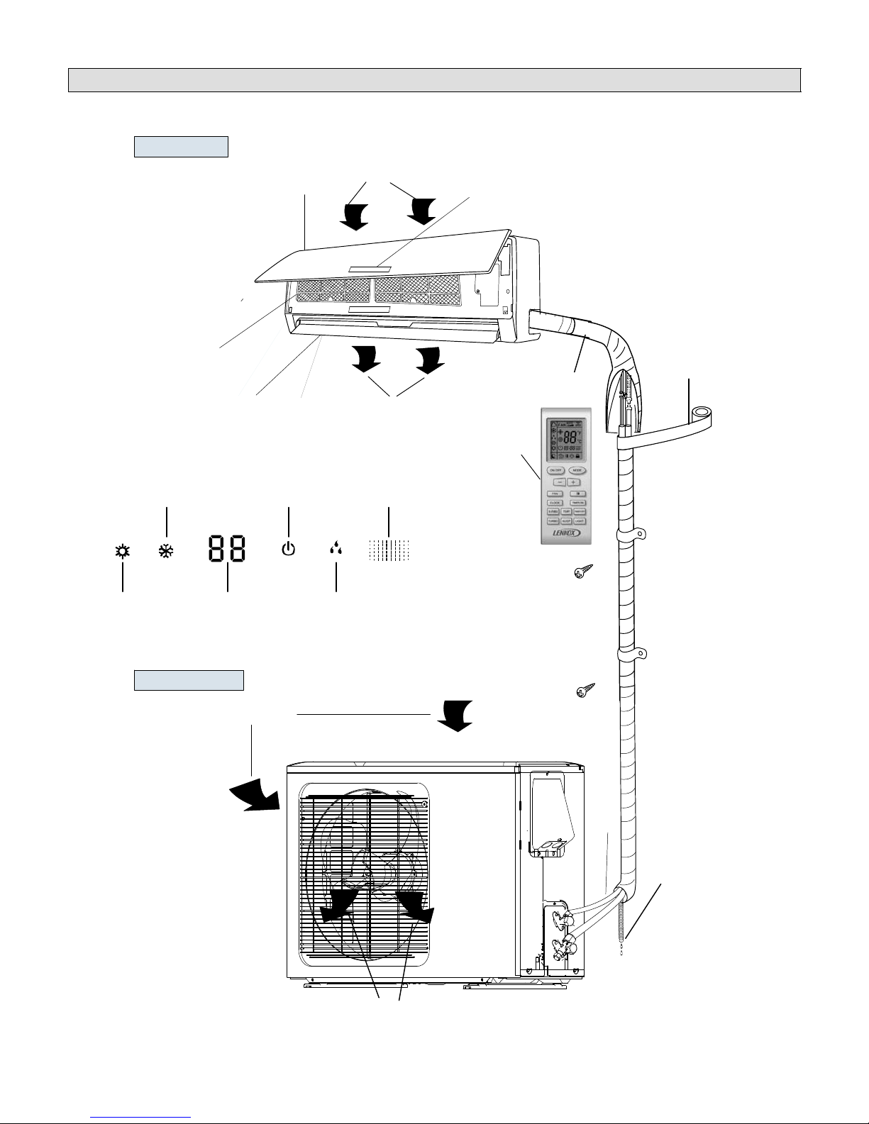
Parts Arrangement
Indoor unit
Filter
Cooling Power/Run
(Typical indoor unit shown. Actual unit may be slightly different.)
Front Panel
Directional Louver
Indoor Unit Display
Air inlet
Display
Wrapping Tape
Wall Pipe
Air outlet
Wireless remote control
Receiver
Heating
Temperature
(or error code)
Outdoor unit
Dehumidification
Setting
Air in
epipnoitcennoC
Drainage hose
Air out
3
Page 4
Important Operating Instructions
To ensure comfort, make sure that temperature selection has been
properly set at the remote control.
To ensure efficient operation, do not block air intake or outlet at either
the indoor or outdoor unit.
Do not stand on outdoor unit or store items on top of unit.
Make sure that indoor unit directional louver is properly adjusted.
IMPORTANT
System Operation
Cooling Operation
In the cooling mode, the indoor coil absorbs the
heat from the room and transfers it to the outdoor
coil where it is discharged. The system cooling
capacity is affected by the outdoor ambient temperature. The indoor fan operates continuously in
the COOL mode. The indoor unit directional louver is fixed in an upward position.
If the unit is in the cooling mode, frost will form on
the indoor coil when the outdoor ambient temperature reaches approximately 32°F (0°C). Typically, when the outdoor ambient temperature falls
below 32°F (0°C), the indoor unit control locks out
operation to protect the system.
In cooling mode, the operating range of the outdoor unit is typically from 41°F (5°C) to 115°F
(46°C).
Heating Operation
The refrigerant flow is reversed during the heating
cycle. In this case, the outdoor coil absorbs the
heat from outside and transfers it to the indoor coil
where it is discharged into the room. The system
heating capacity is also limited by the available
heat in the outdoor ambient air.
In the HEAT mode, the indoor fan will remain OFF
for two minutes in the following instances:
at the beginning of each heating cycle,
after a defrost cycle has ended,
In the heating mode, the indoor blower will contin-
ue to operate for 60 seconds after the outdoor unit
has shut off. The indoor unit directional louver is
fixed in a downward position.
In climates with very low winter temperatures, it
may be necessary to supplement heating by additional means (space heater, fireplace, etc.).
AUTO Mode Operation
When the system is set to operate in AUTO mode,
the indoor and outdoor units work together to
meet a series of preset demands. The remote
control temperature setpoint and fan operation
functions are not adjustable in the AUTO mode.
In AUTO mode, if the indoor ambient temperature
is greater than 77°F (25°C), the unit will operate
in the cooling mode. The outdoor unit will run until
the indoor ambient temperature reaches 75°F
(24°C). At this point, the outdoor unit compressor
and outdoor fan will operate for another 60 seconds, then they will both turn off. The indoor fan
will run continuously at a speed determined by the
indoor ambient temperature. During AUTO cooling operation, the indoor unit directional louver is
fixed in an upward position.
Heat Pump Systems Only −− In AUTO mode, if the
indoor ambient temperature is less than 68°F
(20°C), the unit will run in heating mode. The outdoor unit will run until the indoor ambient temperature reaches 69°F (21°C). At this point, the outdoor unit compressor and fan will operate for
another 60 seconds, then they will both turn off.
The indoor fan will run continuously at a speed
determined by the indoor ambient temperature.
During AUTO heating operation, the indoor unit
directional louver is fixed in a downward position.
FAN Mode Operation
When the system is set to operate in FAN mode,
the indoor fan runs continuously in AUTO, low,
medium or high speed. The outdoor unit is off. In
AUTO fan mode, the fan speed is determined by
the indoor ambient air temperature.
DEHUMIDIFICATION Mode Operation
In heating mode, the operating range of the outdoor unit is typically from 05°F (−15°C) to 86°F
(30°C).
When the system is set to operate in DEHUMIDIFICATION mode, the indoor fan runs continuously in low speed.
4
Page 5

Wireless Remote Functions
The wireless remote control provides system control to the homeowner at the touch of a
button. The indoor unit and remote control send information back and forth continuously.
The remote control must be placed on a table or other surface in direct line of sight with
the indoor unit infrared receiver. The remote control should not be placed in a drawer.
Make sure that there are no obstructions between the indoor unit receiver and the remote
control. Do not drop the control or spill liquid on the remote control.
ON/OFF button
Press this button once to
turn system on. Press again
to turn the system off. When
the ON/OFF button is used
to turn the system OFF, it
overrides the Sleep Timer
function (when it is in use).
+/− buttons
Use plus (+) and minus (−)
buttons to adjust the temperature setting up and down.
NOTE − The temperature
cannot be adjusted when
the system is in AUTO
mode.
FAN button
Press this button to select
fan speed. AUTO fan is the
default setting. In AUTO
fan mode, the indoor fan
speed is determined by the
indoor ambient temperature. Press FAN button to
step through FAN setting
selections: AUTO, low
speed, medium speed and
high speed.
Selected fan speed is
shown at the top of the remote control display.
AUTO
Low Medium High
NOTE − The fan speed is
not adjustable during
DEHUMIDIFICATION
mode operation. The low
fan speed is necessary to
ensure optimal humidity
control.
°F
°C
MODE button
Press this button to select system operating modes. AUTO
mode is the default setting.
Press MODE button again to
select COOL mode, again for
DEHUMIDIFICATION mode,
again for FAN mode and again
for HEAT mode (heat pumps
only).
Selected mode is displayed on
both remote and indoor unit
cover panel.
AUTO
COOL
DEHUMIDIFICATION
FAN
HEAT
LOUVER SETTING button
Press this button to set the
position of the indoor unit directional louver.
When feature is turned on,
icon appears and
louver oscillates through five
positions from up to down
and back again. Continue to
press button to select one of
five fixed positions or one of
three other oscillating settings.
OFF
5
Page 6

Wireless Remote Functions (Continued)
CLOCK button
Use the CLOCK button to adjust the time displayed on the
remote control. Press the
CLOCK button once. The
clock icon will flash. Within 2 seconds, use the − and +
buttons to adjust the time
down or up in one−minute increments. Press the button
continuously to adjust the
time in 10−minute increments.
Press the CLOCK button
again when correct time is
displayed.
X−FAN button
Use the X−FAN button to
extend low speed blower
operation for 10 minutes
at the end of a cooling
demand.
The extended fan operation
ensures that excess moisture
is removed from the indoor
coil before the blower shuts
off.
Press the X−FAN button once
to initiate extended blower
operation. Fan operation
ends after 10 minutes.
The extended fan operation
icon is displayed when the
feature is turned on.
X−FAN operation is available
in cooling or dehumidification
modes; X−FAN is not available in AUTO, heating or fan
mode.
TURBO button
Use the TURBO button to initiate or cancel high−speed fan
operation to accelerate cooling
or heating of the ambient room
temperature. The turbo icon
is displayed when the function
is turned on.
°F
°C
TEMP button
Use the TEMP button to
change the temperature display shown on the remote
control. When initially powered on, the current temperature setting is displayed,
along with the icon.
Press the TEMP button
once to alter the display to
show the current indoor
ambient temperature, along
with the icon. The indoor
temperature sensor is in the
indoor unit.
Press the TEMP button
again to display the outdoor
ambient temperature
icon . The outdoor ambient temperature display is
not available on this system.
On occasion, the remote
control will display the
temperature that was not selected (indoor ambient temperature or setting temperature). The selected temperature will return to the display
screen after 5 seconds.
NOTE − The TEMP button
can also be used to temporarily display the indoor ambient temperature on the indoor unit display panel.
LIGHT button
Use the LIGHT button to turn
the indoor unit display light
on and off. When the light is
on, the icon appears on
the remote control.
6
Page 7

Wireless Remote Functions (Continued)
SWITCH FROM °C TO °F
With system OFF, press
MODE and − buttons
simultaneously to switch
from Centigrade to
Fahrenheit. Current
selection is displayed to
the right of the temperature
display.
REMOTE LOCK
Press − and + buttons simultaneously to either lock
or unlock the remote control buttons. When locked,
the icon is displayed.
SLEEP button
Use the SLEEP button to
initiate or cancel the sleep
function. Press SLEEP button. When sleep icon
appears, press TIMER
OFF button and use − and
+ buttons to set time for
system shutdown. When
desired time is displayed,
press TIMER OFF button
again. Press SLEEP button
to cancel sleep function.
In cooling mode, SLEEP
function increases temperature (+1.8°F per hour)
over a two−hour period after the selected sleep time.
In heating mode, SLEEP
function decreases temperature (−1.8°F per hour) over
a two−hour period after the
selected sleep time.
NOTE − The sleep function
is not available in AUTO or
FAN modes.
°F
°C
TIMER ON button
Use the TIMER ON button
to initiate or cancel a single
timed−on event. Use this
feature to bring the system
on just before you return
home or just before you
wake in the morning.
Press the TIMER ON
button once. The clock
icon disappears and a
time setting appears with
the word ON flashing at the
right. Use the − and + keys
to adjust the time setting to
the desired time for the
system to begin operation.
Press the TIMER ON
button again to accept the
setting. When successfully
set, the word ON will appear to the right of the current time display. Press the
TIMER ON button again if
you want to cancel the
timed−on event.
TIMER OFF button
Use the TIMER OFF button
to initiate or cancel a single
timed−off event. Use this
feature to turn the system
off just after you leave the
house or just after you go
to bed at night.
Use the same method
described above to set the
desired time for the system
to stop operation. When
successfully set, the word
OFF will appear to the right
of the current time display.
Press the TIMER OFF button again if you want to
cancel the timed−off event.
7
Page 8

System Start Up Using Wireless Remote
General Operation
1 − Press ON/OFF button once to turn system on.
2 − Press MODE button until desired operating
mode icon is displayed.
NOTE − When AUTO mode is selected, the
temperature setting is not displayed on the
remote control. The − and + buttons cannot be
used to make temperature setting selections.
°F
3 − Press − or + buttons until desired temperature
setting is displayed.
NOTE − Skip this step in AUTO mode.
4 − Press FAN button until desired fan speed icon
is displayed.
NOTE − Fan speed will be set to low if
DEHUMIDIFICATION mode has been selected.
5 − Press OSCILLATE button. Indoor unit
directional louver will open and begin to
oscillate. If a single setting is preferred, press
button again when louver is in the desired
position. Louver will remain in desired position
until system is powered off.
Special Functions
6 − Press SLEEP button initiate sleep function.
Then press TIMER OFF button to set timed
off.
7 − Use TIMER ON and TIMER OFF buttons to
schedule desired timed on and off settings.
8 − Use LIGHT button to set display light on or
off.
°C
1 2
4
9
10
6
3
5
7
8
9 − Use X−FAN button to turn on and off extended
fan operation feature.
10−Use TURBO button to turn accelerated fan
speed on or off.
8
Page 9

Remote Control Batteries
The wireless remote control requires two AAA, 1.5V batteries. DO NOT attempt to use any other type of battery.
Follow the steps below and in the illustrations to replace the
batteries when necessary.
1 − Place thumb on at the top of the battery access
panel on the back of the remote control. Slide the panel
in the direction of the arrow.
2 − Remove the existing AAA, 1.5V batteries.
3 − Replace batteries with fully charged AAA, 1.5V batteries.
NOTE − Pay attention to proper polarity of batteries. Remote control will not operate if batteries are improperly
installed.
4 − Reposition battery access panel and slide forward until
panel snaps into locked position.
IMPORTANT !
If wireless remote will not be used for a long period of
time, remove batteries to avoid damage to the control.
The remote control must be placed on a table or other sur-
face in direct line of sight with the indoor unit infrared receiver. The control should not be placed in a drawer. Make
sure that there are no obstructions between the indoor unit
receiver and the remote control.
Remote should remain within its receiving range to ensure proper system control.
Control should be kept at least 3 feet (914mm) away from other electrical appliances
(televisions, stereos, etc.) to prevent signal interference.
If remote control operation becomes erratic, remove batteries. Wait 30 seconds and
reinsert batteries. If proper remote operation is not restored, replace batteries.
Auto ON Switch
If the remote control is lost or damaged, or if
charged AAA, 1.5V batteries are not available, the Auto ON switch can be used to turn
the system on or off.
AUTO
The Auto ON switch is located behind the
cover panel on the indoor unit. Lift the front
panel and press the ON button once briefly to
start the system. To stop emergency opera-
PENCIL OR OTHER
NON−METALLIC OBJECT
tion, push the ON button again.
AUTO Switch
IMPORTANT !
The Auto ON button initiates operation in
the AUTO mode. The temperature and fan
speed are not adjustable in the AUTO
mode.
AUTO BUTTON
(Not Recessed)
PRESS
WITH
FINGER
AUTO Switch
(Recessed)
9
Page 10

Maintenance
WARNING!
Turn off all power to unit at unit disconnect switch or
circuit breaker before performing any maintenance
procedures! Failure to follow this warning could
lead to personal injury or death.
Coil fins are very sharp! Take care not to touch the fins
in order to avoid injury.
Indoor Unit Filters
The indoor unit filter should be cleaned every three months,
or more frequently, if necessary.
Follow the steps below and in the illustrations to clean the
filters.
1 − Pivot indoor unit front panel out and up to access filters.
2 − Gently pull each filter outward, then down to remove the
filters from the unit
3 − Use a vacuum cleaner to remove dust and dirt from
each filter or wash the filters with warm water and a mild
detergent. Rinse filters thoroughly with clean water and
set aside to air dry.
CAUTION!
Do not use hot water to clean the filters. Exposure to
water temperatures above 113°F (45°C) will damage
filter media and frame.
1
2
3
4
4 − Reinsert clean, dry filters and close unit front panel. Re-
store power to unit.
Indoor Unit
Check to make sure that there are no objects on top of unit or around unit that may be obstructing air flow. Check to make sure that indoor unit and wall bracket are secure and have
not been damaged. Use a clean, dry cloth to gently remove dust from the outer surface of the
indoor unit. The cloth may be slightly dampened with warm water, if necessary. Do not use
soap or other cleaners.
CAUTION!
Hot water, soaps or other cleaning agents may damage indoor unit cabinet or display
panel. Do not use hot water (above 113°F [45°C]). Cloth must be damp only −− NEVER
WET to avoid damage to display. Do not use soap or other cleaning agents (window
cleaner, abrasive cleansers, etc.) to clean the indoor unit cabinet.
Outdoor Unit
Check to make sure that there are no objects on top of unit or around unit that may be obstructing air flow. If the outdoor unit is installed on a wall bracket, make sure that bracket is
secure and has not been damaged. Use a clean, slightly dampened cloth to gently remove
dust from the outer surface of the outdoor unit. Do not use soap or other cleaners and DO
NOT spray water into unit.
WARNING!
SHOCK HAZARD! DO NOT SPRAY water into outdoor unit. Failure to follow this warning could lead to electrical shock, resulting in personal injury or death.
10
Page 11

Troubleshooting
WARNING!
ELECTRICAL SHOCK HAZARD! Never attempt to repair the indoor or outdoor unit yourself.
System repairs must be performed by a licensed, professional technician, or equivalent.
If any of the following conditions exist, immediately turn the system (indoor and outdoor
units) off at the unit disconnect switch and call a licensed professional technician, or equivalent, for repairs
D There is a very loud sound during unit operation.
D There is a terrible odor coming from the indoor unit during operation.
D Water is leaking into the room.
D The circuit breaker trips frequently.
D Water or some other liquid has been splashed into the indoor unit.
If none of the above conditions exist, check the following items before calling for repairs. This can
save you both time and money.
Problem Possible Cause
Unit does not operate immediately when restarted. Unit control initiates a 3−minute delay at the end of
each cycle to protect the compressor from dam-
age.
A whoosh or gurgling noise can be heard at the
indoor unit.
Mist is coming out of the indoor unit during cooling
operation.
A creaking or popping noise can be heard when
the unit starts or stops.
Unit is not operating. Are the TIMER ON and TIMER OFF features be-
Sometimes, the refrigerant can be heard in the
indoor coil when the outdoor unit starts or stops
operation. This is not a malfunction.
This sometimes happens when the indoor temper-
ature and humidity are very high and the air is be-
ing cooled quickly. The mist will disappear as the
indoor temperature and humidity are lowered.
The plastic components of the indoor units some-
times expand and contract when they are heated
and cooled.
ing used incorrectly?
Is power disconnected or has circuit breaker
tripped.
Is power shut down?
System is not cooling (or heating) efficiently. Is temperature setting correct?
Wireless remote is not working. Is remote in direct line of sight with indoor unit in-
Water is leaking from indoor unit. Indoor humidity level is very high and water is be-
Are either the air inlet or air outlet blocked on the
outdoor or indoor unit?
Is filter dirty?
Is fan at low speed?
Are windows and doors properly shut?
frared receiver? Has the remote been damaged?
Remove remote control batteries for 30 seconds,
then reinsert them. Replace batteries, if neces-
sary.
ing blown from indoor coil. This will stop as humid-
ity level is reduced.
11
Page 12

Troubleshooting (Continued)
Problem Possible Cause
Water is leaking from condensate line at
indoor unit.
Check condensate line outside to make sure it is
not obstructed.
Check condensate line to make sure it has not
been disconnected from indoor unit.
Water is leaking from the outdoor unit. During operation in high−humidity areas, conden-
sate will form on cold outdoor refrigerant pipes.
When heat pump is operating in defrost mode, ice
will thaw from around outdoor coil and water will
flow from the unit.
Clicking noise heard inside. Sometimes, the sound of the outdoor unit fan or
compressor relay can be transmitted in a way that
makes it seem to be coming from the indoor unit.
Indoor fan is not working. Heat pump units −− In HEAT mode, a timed delay
keeps indoor fan off for two minutes to prevent
unheated air from being circulated by the indoor
fan.
Heat pump units −− In HEAT mode, cold outdoor
temperatures and high humidity cause frost to ac-
cumulate on the outdoor unit. When this happens,
the unit will enter a defrost cycle. The indoor fan is
off during the 3 − 12 minute cycle.
In DEHUMIDIFICATION mode, indoor fan opera-
tion may be stopped to avoid delivery of moist air
to the room. Do not adjust temperature setting.
Error Codes
If a problem occurs with the system, an error code will replace the temperature setting displayed on
the front cover of the indoor unit. If more than one error has occurred, the codes will alternate so
that all codes are shown. Make note of the code (E4, F6, H4, etc.), then reset the display by pressing
the ON/OFF button on the wireless remote. Press the ON/OFF button a second time to reapply power to system. If code is still displayed, disconnect and restore power at the unit disconnect switch
or circuit breaker. If the problem was temporary, the code will not reappear. If the error code re−appears after power has been broken and restored at the disconnect switch or circuit breaker, call a
licensed professional service technician.
88
* The temperature readout will be replaced
by an error code if there is a malfunction.
RUN
SIGNAL
INFRARED
RECEPTOR
HEAT INDICATOR
TEMPERATURE*
COOL INDICATOR
12
DEHUMIDIFY MODE
 Loading...