

Page 1
APPLICATION
GUIDE
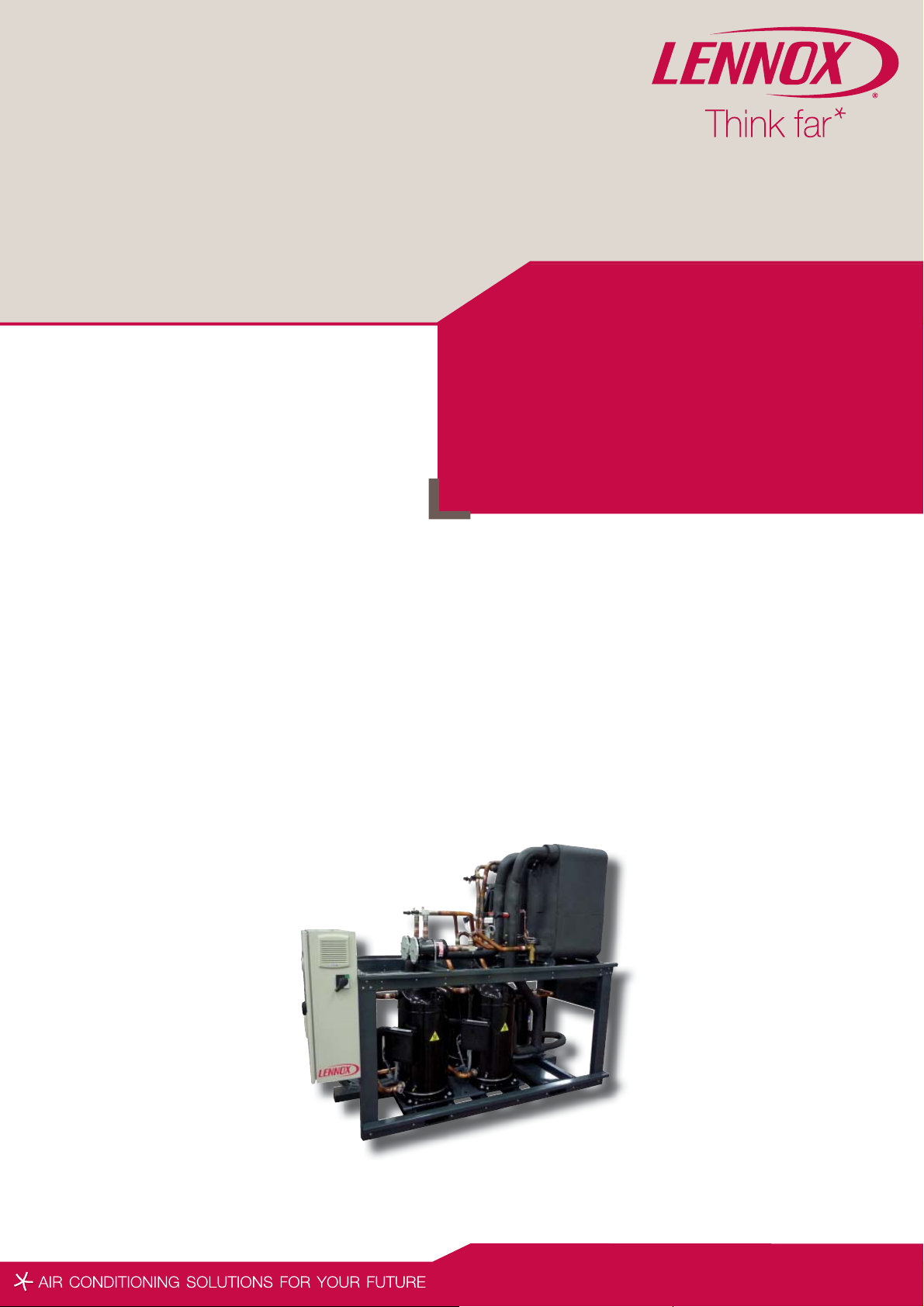
Water cooled chillers
Heat pumps
MWC
MWR
180 720 kW
MCW-AGU-0410-E
lennoxemeia.com
Page 2

Page 3
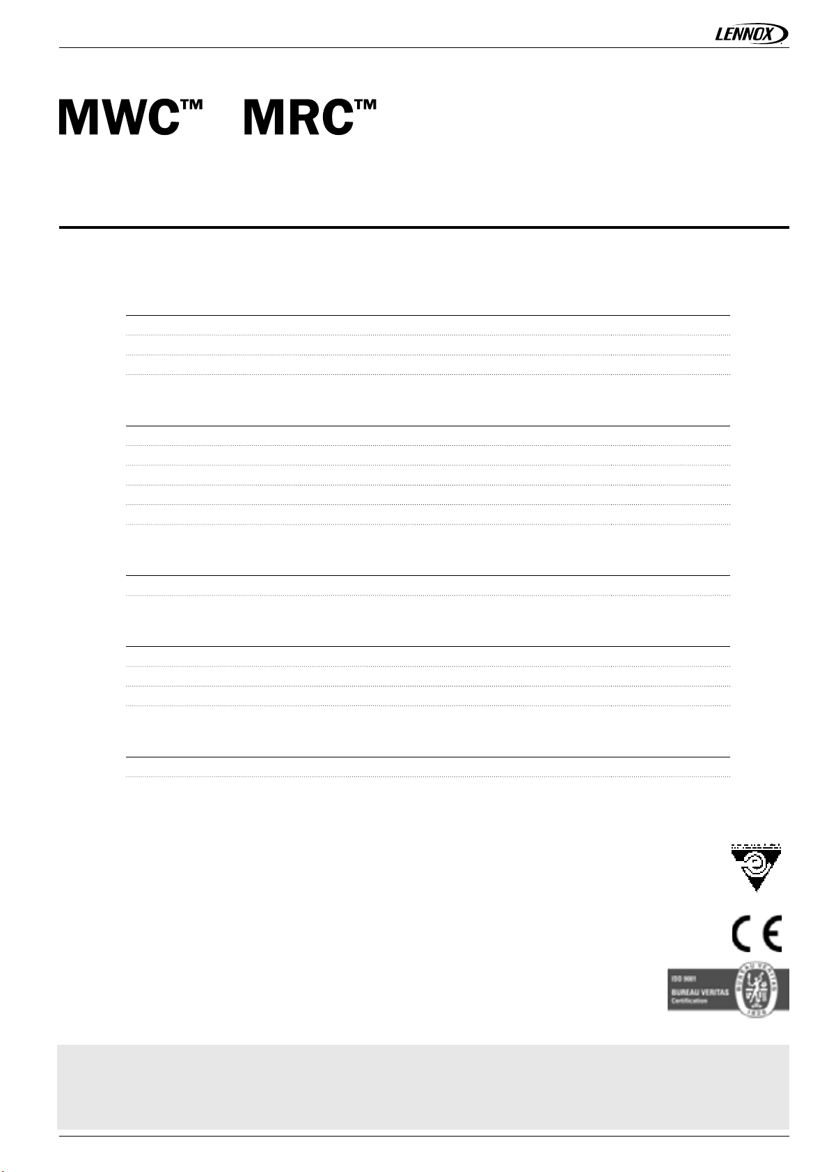
TABLE OF CONTENTS
APPLICATION GUIDE
1.
GENERAL
Features and benefi ts
Options and accessories
Model number description
2.
GENERAL DATA
General data
Pressure drops
Hydraulic data
Acoustic data
Operating limits
Ref : MWC-AGU-0410-E
2
4
5
6
10
11
12
13
ELECTRICAL DATA
4.
Electrical tables
PERFORMANCES
5.
MWC - Cooling mode
MRC - Cooling mode
MWC - Heating mode
DIMENSIONAL DATA
6.
Dimensional data
14
15
16
17
18
Our company is member of the Eurovent certifi cation program.
The MWC™ Lennox chillers are tested and rated in accordance with Eurovent certifi cation program.
Our products comply with the European standards.
Product designed and manufactured under a quality management system certifi ed ISO 9001.
All the technical and technological information contained in this manual, including any drawing and technical descriptions provided
by us, remain the property of Lennox and must not be utilised (except in operation of this product), reproduced, issued to or made
available to third parties without the prior written agreement of Lennox.
Application Guide • MWC-0410-E • 1 •
Page 4
FEATURES AND BENEFITS
Water cooled liquid chiller for indoor installation
GENERAL CHARACTERISTICS OF THE UNIT
The MWC unit is designed for industrial and commercial
applications where customers require reduced total cost of
ownership for new air conditioning equipment.
As main characteristics the MWC unit offers multi scroll
R410A compressors with two circuits for safety operation and
oversized heat exchangers for high full and part load energy
performances (Class B effi ciency / ESEER > 6.0).
The MWC is the solution for indoor installation. Thanks to
very compact dimensions and limited footprint MWC can be
installed easily into any technical room.
The MWC is available in 2 main versions to meet all customer
requirements and applications :
- MWC version is the water-cooled chiller. This version can
be used for air conditioning applications in association with
a separate dry-cooler or using ground water. The MWC version can also be used for heating applications. With the “hot
water set point control” option the MWC range can supply
hot water up to +50°C.
- MRC version is the split version without condenser. This
version can be used for air conditioning applications in association with a remote air-cooled condenser
COMPRESSOR
MWC is using R410A vibration-free compliant® scroll compressors
to guarantee a low operating sound level, a high durability and
reliability and no maintenance.
- Exclusive Compliant® Scroll design with both axial and radial
compliance to increase compressor operation tolerance to
liquid refrigerant, substantially improving durability and reliability.
- Motor cooled by suction gas.
- Electronic control of the compressor discharge temperature.
- Motor protection device against high temperature or over
current situations.
- Discharge non-return valve.
- Compressors assembly installed on an independent chassis
supported by anti-vibration mountings.
- Optional sound-proofed panel enclosures to reduce noise
emissions.
WATER HEAT EXCHANGER (EVAPORATOR
AND CONDENSER)
MWC is using stainless steel brazed plate heat exchangers with
true dual circuit.
REFRIGERANT CIRCUIT
MWC is using R410A refrigerant in 2 independent circuits that
allows operation at 50% of the capacity in case of issue on one
circuit.
Each circuit includes:
- A refrigerant charge reduced by 30% thanks to the use of
R410A combined with plate heat exchanger
- Suction piping with thermal insulation.
- Moisture sight glass on the MRC version
- Filter drier with removable cartridge fi lter.
- Thermostatic valve or electronic expansion valve (optional
from size 180 to 570, standard on size 650 & 720).
- Temperature sensors and pressure transducers.
- Leak-tight refrigerant circuit with brazing carried out under
nitrogen by certifi ed technicians.
- Each refrigerant circuit is pressure and leak tested with a
Hydrogen/Nitrogen mixture, and vacuumed before being
charged with refrigerant. All units are then subjected to a
complete functional and operational run test to guarantee
perfect sealing before leaving the factory.
- Copper brazed stainless steel plate heat exchanger.
- 13 mm closed cell thermal foam insulation.
- Evaporator protected against freezing risks thanks to an
electronic water fl ow switch
- Condenser protected against low condensing temperature
thanks to a 0-10 V output signal available from the controller
to control a condenser water inlet valve (Not from Lennox
supply).
CASING/CHASSIS
- Chassis made of galvanised steel sheet metal painted with
a RAL 7016 (grey) powdered polyester paint.
- Optional casing with removable panels made of galvanised
steel sheet metal painted with a RAL 7016 (grey) powdered
polyester paint.
• 2 • Application Guide • MWC-0410-E
Page 5

FEATURES AND BENEFITS
ELECTRICAL BOX
The MWC is designed for 400V/3/50Hz supply.
- Unit electrical cabinet, components and wiring in compliance
with EN 60204-1 electrical directive.
- 400V/3/50Hz power supply (without neutral) with a single
point of power connection.
- IP24 protection class.
- Recognized brand electrical components for ease of maintenance.
- Main on/off switch mounted on the front panel.
- DC50 user interface mounted on the front panel.
- 400/24 V transformer to supply the control circuit.
- Labelled electrical wires to facilitate maintenance and diagnostic.
- Optional power and control circuit for the pumps.
CONTROL
CLIMATIC™ microprocessor based control is providing the
following functions:
- 4 scheduling time zones per day over 7 days to allow energy
consumption management according to the building use and
environmental constraints.
- PI control of the water temperature with operating time
equalisation of the compressors.
- Intelligent advanced control algorithm to protect the compressors against excessive short-cycling and to allow operation
of the unit without buffer tank in most comfort air conditioning
applications (e.g. unit with fan-coils). Refer to minimum installation water loop volume recommendations.
- Water pump control with operating time equalization and
automatic change-over in case of a pump fault (Twin pump
only).
- Master/slave or cascade control of two chillers operating
in parallel with operating time equalization and automatic
change-over in case of a unit fault.
CLIMATIC™ is pre-factory confi gured with default settings
allowing a fast commissioning on site. The DC50™ user interface
with graphical display is easy to use, intuitive. Main customer
parameters can be read or modifi ed without main power shut-off
(Entering/leaving water temperatures, alarms, water set-points,
high and low pressure readings).
The DS50™ service display (optional) is a .plug and play"
controller that allows service people to read and modify all
unit parameters (Unit settings, operating time and number of
compressor starts, low and high pressure reading, read the
history of last 32 faults...).
COMMUNICATION
The control board is equipped with a RS485 serial communication
port to allow remote management through communication
bus.
According to the wished communication protocol, our control
board can be fi tted with ModBUS®, LonWorks® or BacNET®
communication interface (options).
The main control board has free dry contacts that allow remote
control of the unit by wired cable:
- Remote on/off of the unit.
- Remote alarm reset to re-start the unit.
- Alarm or alert indications.
- Free customer contact.
With the optional extension board BE50, it is possible to get
additional customized digital or analog inputs/outputs for remote
control of the unit:
- Fault pumps (dry contact).
- Operation indication at 100% on circuit 1 or 2 (dry
contact).
- Dual water set-point management (dry contact).
- Force heating or cooling mode (24V AC input).
- Power limitation by disabling circuit 1 or 2 (24V AC input).
- Force unoccupied mode (24V AC input).
- Water set-point offset based on a 4-20mA signal.
DIRECTIVES
The unit is built to meet European norms and standards &
Eurovent certiFIcation performance standards.
. DI 97/23/CE Pressure Equipment Directive.
. DI 98/37/CE Machinery Directive.
. DI 73/23/CE Low Voltage Directive.
. DI 89/336/CE Electro Magnetic Compatibility Directive
. EN 378-2 Safety and Environmental Directive.
. The European Restriction of the Use of Certain Hazardous-
Substances (RoHS).
Application Guide • MWC-0410-E • 3 •
Page 6
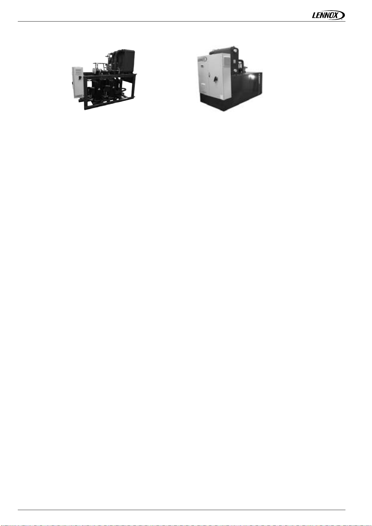
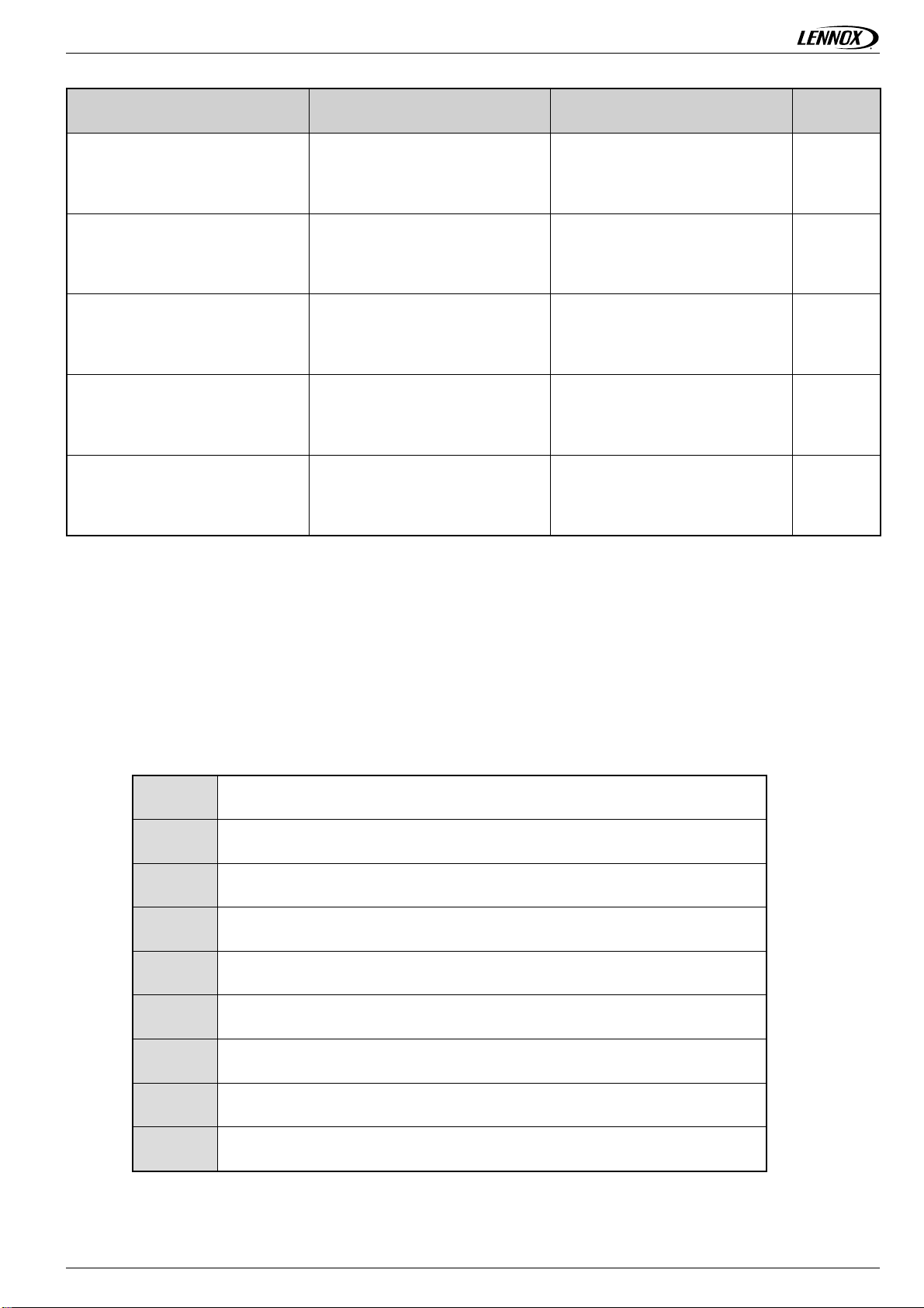
OPTIONS AND ACCESSORIES
OPTIONS DESCRIPTION ADVANTAGES MODELS
Control/Power electrical equipment of
single evaporator pump
Control/Power electrical equipment of
dual evaporator pump
Control/Power electrical equipment of
single condenser pump
Control/Power electrical equipment of
dual condenser pump
Electronic expansion valve
Evaporator fi lter (supplied loose)
Unit equipped with electrical power
and control circuit for one single
speed pump
Unit equipped with electrical power
and control circuit for dual single
speed pumps.
Unit equipped with electrical power
and control circuit for one single
speed pump
Unit equipped with electrical power
and control circuit for dual single
speed pumps.
Unit equipped with an electronic
expansion valve for smooth operation
in every temperature conditions
1000 microns water fi lter delivered
with piping and Victaulic connections.
Quick start-up on job site.
Quick start-up on job site.
Quick start-up on job site.
Quick start-up on job site.
Allows applications with changing
temperature conditions.
This protection must be fi tted to
protect the evaporator from any
possible impurities.
MWC/MRC
180 ► 720
MWC/MRC
180 ► 720
MWC
180 ► 720
MWC
180 ► 720
MWC
180 ► 570
MWC/MRC
180 ►720
Condenser fi lter (supplied loose)
Evaporator fl ange connections
(supplied loose)
Condenser fl ange connections
(supplied loose)
Hot water set-point control (Heat
pump mode)
DC50™ remote comfort display
(supply loose)
DS50™ service display (supply
loose)
1000 microns water fi lter delivered
with piping and Victaulic connections.
Two connection sleeves with Victaulic
groove and fl ange on opposite side.
Two connection sleeves with Victaulic
groove and fl ange on opposite side
Unit equipped with insulated heat
exchanger and hot water sensor on
condenser side for heating purpose.
Customer display located at 600
meters maximum from the unit.
Plug and play display delivered with 1
meter cable and connector for quick
connection on Climatic controller.
This protection must be fi tted to
protect the condenser from any
possible impurities.
Allow easy connection with fl anges
on customer side.
Allow easy connection with fl anges
on customer side.
Allow heat pump operation.
Remote customer parameter reading
and modifi cation.
Display for service technicians only.
MWC
180 ►720
MWC/MRC
180 ►720
MWC
180 ► 720
MWC
180 ►720
MWC/MRC
180 ►720
MWC/MRC
180 ►720
Communication card using ModBus/
Modbus communication interface
LonWorks® communication interface
• 4 • Application Guide • MWC-0410-E
.
JBus protocol
Communication card using LonTalk®
protocol.
Communication interface with a
building management system.
Communication interface with a
building management system.
MWC/MRC
180 ►720
MWC/MRC
180 ►720
Page 7
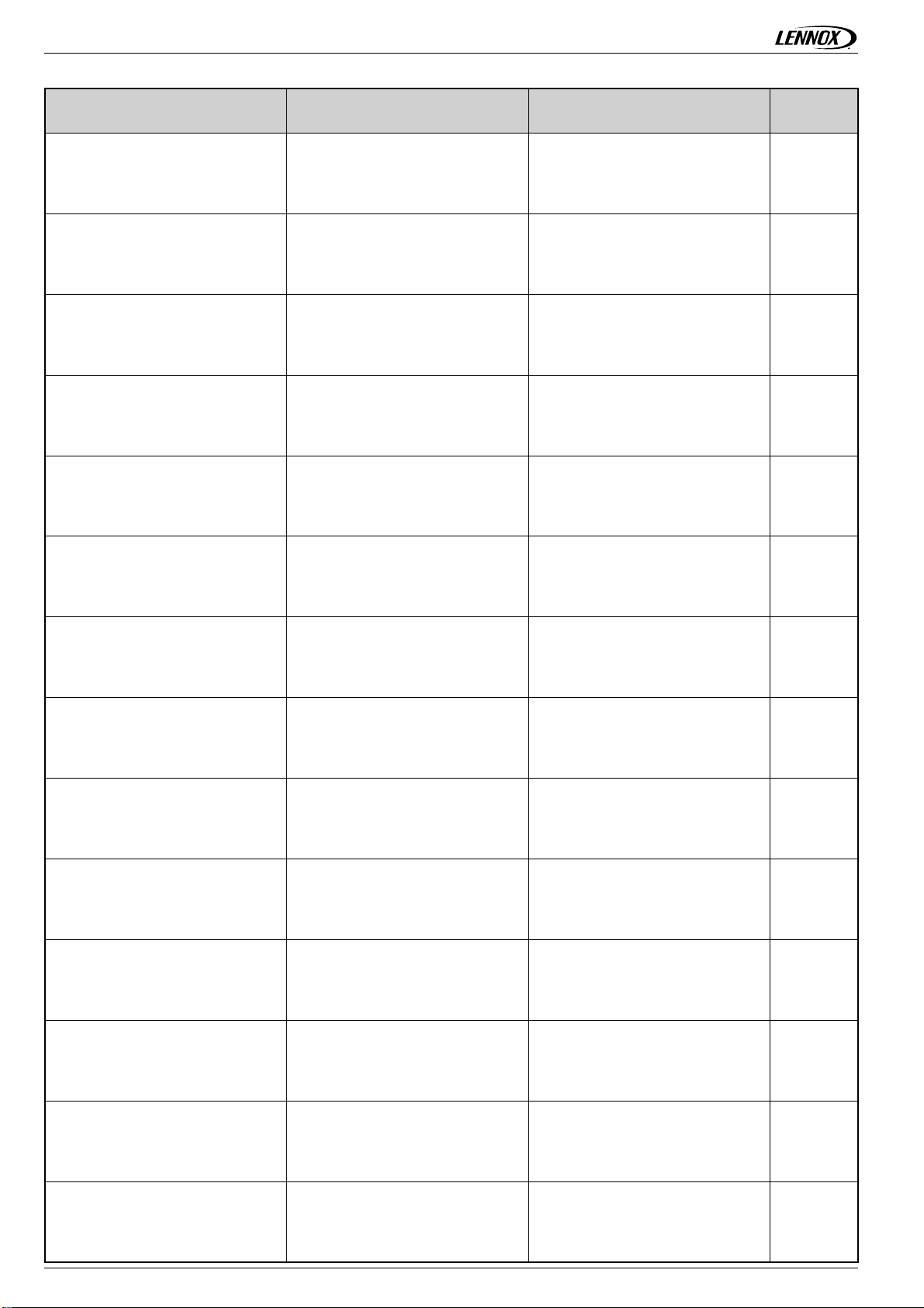
OPTIONS AND ACCESSORIES
OPTIONS DESCRIPTION ADVANTAGES MODELS
BACnet® communication interface
Adalink™ supervision (Customer
friendly web based supervision)
BE50™ extension board for
additional inputs/outputs
Anti-vibration mounts (supplied
loose)
Panel enclosure (compressors)
Communication card using Bacnet®
protocol.
Electronic board with RS485 cables,
RJ11 phone cable, Ethernet cable
and power supply cable.
Electronic extension board with
additional analog inputs (4), digital
inputs (4) and digital outputs (4). See
control manual.
Rubber anti-vibration mounts to be
mounted under the unit.
Unit equipped with removable panels
around the compressors to reduce
sound level.
Communication interface with a
building management system.
Remote supervision of the unit via an
intuitive web page.
Relay card for remote control and
alarm report using dry contacts, 24
Vac or 4-20 mA signals.
Reduction of the transmission of
vibration to the ground.
Reduction of the unit sound power
level.
MWC/MRC
180 ►720
MWC/MRC
180 ►720
MWC/MRC
180 ►720
MWC/MRC
180 ►720
MWC/MRC
180 ►720
MODEL NUMBER DESCRIPTION
EXAMPLE : MWC 200D
M
W
C
200
D
N
M
1
Medium
W = Water cooled
R = Remote condenser
C = Cooling mode
Cooling capacity in kW
Number of circuits :
D = 2 circuits
Non ducted
R410 A refrigerant
Revision number
M
Application Guide • MWC-0410-E • 5 •
400V/3/50 Hz
Page 8
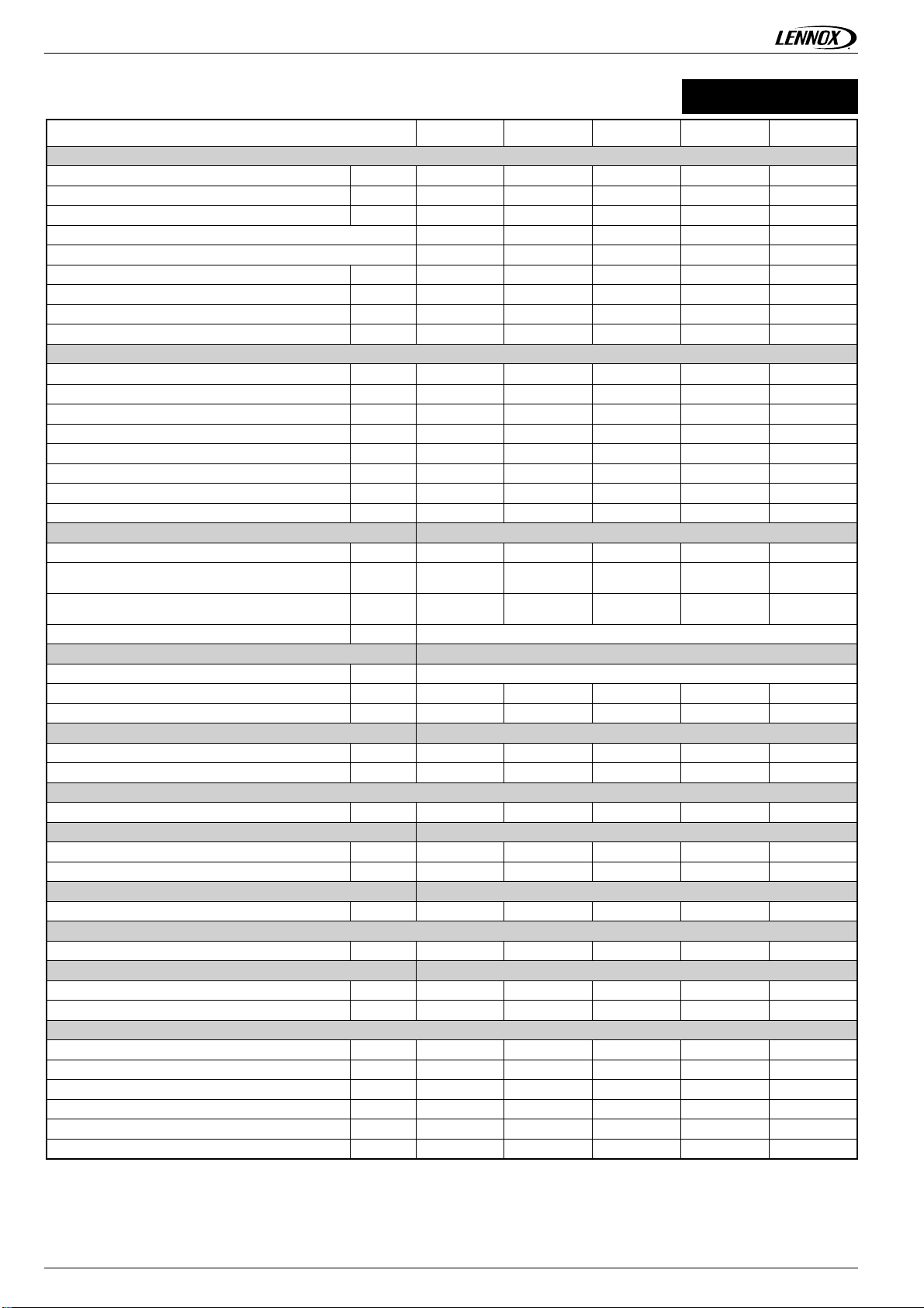
GENERAL DATA
COOLING ONLY
MWC
MWC™ 180 230 280 330 380
Cooling mode
Cooling capacity
Power input
Full load amps
EER 4,74 4,66 4,70 4,70 4,70
(2)
ESEER
Evaporator water fl ow
Evaporator pressure drop
Condenser water fl ow
Condenser pressure drop
Heating mode
Heating capacity
Power input
Full load amps
COP
Condenser water fl ow
Condenser pressure drop
Evaporator water fl ow
Evaporator pressure drop
Compressor Scroll - Hermetic
Number of compressor nr
Capacity steps
Oil charge per compressor
Oil type type MOBIL EAL Arctic 22CC or ICI EMKARATE RL32CF
Refrigerant
Expansion type Thermostatic expansion valve
Number of circuit nr
Charge per circuit
Condenser (Heating mode) AISI 316 stainless steel plate brazed with copper heat exchanger
Water volume
Water operating pressure
Hydraulic connections Victaulic
Water inlet/outlet Inches
Evaporator (Cooling mode) AISI 316 stainless steel plate brazed with copper heat exchanger
Water volume
Water operating pressure
Hydraulic connections Victaulic
Water inlet/outlet Inches
Acoustic
Global sound power level
Electrical data
Start-up intensity
Maximum current
Dimensions
Length
Width
Height
Footprint
Operating weight
Shipping weight
(1)
(1)
(1)
kW
186,1 232,8 280,7 333,6 380,4
kW 39,3 49,9 59,7 70,9 81,0
A 70,6 86,6 101,1 118,1 133,2
6,74 6,31 6,38 6,25 6,03
(1)
(1)
(1)
(1)
(3)
(3)
(3)
m3/h 32,0 40,1 48,3 57,4 65,4
kPa 34,9 28,9 40,7 31,5 40,2
m3/h 37,2 46,7 56,2 66,8 76,2
kPa 46,2 38,3 30,3 41,8 40,5
kW
196,5 246,4 296,9 351,9 401,7
kW 48,5 61,5 73,1 86,9 99,1
A 86,6 110,0 130,7 155,3 177,1
4,05 4,00 4,06 4,05 4,05
(3)
(3)
(3)
(3)
3
/h 33,8 42,4 51,1 60,5 69,1
m
kPa 38,6 32,1 25,4 34,8 33,7
m3/h 32,0 40,1 48,3 57,4 65,4
kPa 34,9 28,9 40,7 31,5 40,2
44444
%
l
20-50-75-
100%
(2 x 3,2)
+ (2 x 3,2)
21-43-62-83-
100%
(3,2+6,3)
+ (2 x 3,2)
21-36-53-71-
85-100%
(3,2+6,3)
+ (3,2+6,3)
15-46-61-87-
100%
(2 x 6,3)
+ (3,2+6,3)
25-50-75-
100%
(2 x 6,3)
+ (2 x 6,3)
R410A
22222
kg8 12141422
l 13 24 35 35 43
kPa 600 600 600 600 600
4" 4" 4" 4" 4"
l 13 24 24 35 35
kPa 600 600 600 600 600
4" 4" 4" 4" 4"
(1)
dB(A) 81 87 89 90 92
400V / III / 50 Hz
A 266,9 402,9 431,7 460,1 488,3
A 123,8 152,2 181,0 209,4 237,6
mm 2150 2150 2150 2150 2150
mm 820 820 820 820 820
mm 1645 1870 1870 1870 1870
m² 1,8 1,8 1,8 1,8 1,8
kg 756 974 1158 1328 1534
kg 736 914 1088 1248 1444
All data are at Eurovent conditions :
(1) Gross cooling capacity with 12/7°C evaporator water temperature and
30/35°C condenser water temperature.
(*) Except for MWC 720 :13/7°C evaporator water temperature.
(2) ESEER according to EN14511 Eurovent calculation method.
(3) Gross heating capacity with 40/45°C condenser water temperature and 10°C
evaporator water inlet, with the same evaporator water fl ow as in cooling
mode.
OPERATING LIMITS on page 13
• 6 • Application Guide • MWC-0410-E
Page 9

GENERAL DATA
COOLING ONLY
MWC
MWC™ 450 510 570 650 720 (*)
Cooling mode
Cooling capacity
Power input
Full load amps
EER 4,66 4,59 4,66 4,57 4,44
(2)
ESEER
Evaporator water fl ow
Evaporator pressure drop
Condenser water fl ow
Condenser pressure drop
Heating mode
Heating capacity
Power input
Full load amps
COP
Condenser water fl ow
Condenser pressure drop
Evaporator water fl ow
Evaporator pressure drop
Compressor Scroll - Hermetic
Number of compressor nr
Capacity steps
Oil charge per compressor
Oil type type MOBIL EAL Arctic 22CC or ICI EMKARATE RL32CF
Refrigerant
Expansion type Thermostatic expansion valve
Number of circuit nr
Charge per circuit
Condenser (Heating mode) AISI 316 stainless steel plate brazed with copper heat exchanger
Water volume
Water operating pressure
Hydraulic connections Victaulic
Water inlet/outlet Inches
Evaporator (Cooling mode) AISI 316 stainless steel plate brazed with copper heat exchanger
Water fl ow
Water volume
Hydraulic connections Victaulic
Water inlet/outlet Inches
Acoustic
Global sound power level
Electrical data
Start-up intensity
Maximum current
Dimensions
Length
Width
Height
Footprint
Operating weight
Shipping weight
All data are at Eurovent conditions :
(1) Gross cooling capacity with 12/7°C evaporator water temperature and
30/35°C condenser water temperature.
(*) Except for MWC 720 :13/7°C evaporator water temperature.
(2) ESEER according to EN14511 Eurovent calculation method.
(1)
(1)
(1)
kW
442,9 499,0 570,3 642,3 715,5
kW 95,0 108,7 122,3 140,6 161,1
A 154,0 177,6 201,0 230,9 264,5
6,04 6,04 6,09 5,97 5,67
(1)
(1)
(1)
(1)
(3)
(3)
(3)
m3/h 76,2 85,9 98,1 110,5 102,6
kPa 40,4 50,5 46,0 57,7 50,0
m3/h 88,7 100,4 114,4 129,3 143,7
kPa 43,6 51,0 61,6 34,0 41,5
kW
468,3 530,4 602,6 682,1 750,6
kW 116,3 133,0 149,7 169,9 192,8
A 207,9 237,8 267,5 303,8 344,6
4,03 3,99 4,03 4,01 3,89
3
m
/h 80,6 91,2 103,7 117,4 129,1
kPa 36,4 42,6 51,1 28,4 34,0
m3/h 76,2 85,9 98,1 110,5 102,6
kPa 40,4 50,5 46,0 57,7 50,0
66666
18-36-53-70-
%
85-100%
(3 x 6,8)
l
+ (3 x 6,8)
16-37-51-70-
83-100%
(3 x 6,8)
+ (3 x 6,3)
18-36-53-70-
85-100%
(3 x 6,3)
+ (3 x 6,3)
16-37-52-70-
83-100%
(3 x 6,3)
+ (3 x 6,3)
18-37-53-70-
85-100%
(3 x 6,3)
+ (3 x 6,3)
R410A
Electronic
expansion valve
22222
kg 27 29 31 30 30
l 52 56 61 77 77
kPa 600 600 600 600 600
5" 5" 5" 5" 5"
(1)
43 43 61 61 61
600 600 600 600 600
5" 5" 5" 5" 5"
(1)
dB(A) 92 93 93 96 97
400V / III / 50 Hz
A 495,9 563,1 606,9 734,3 778,4
A 268,6 312,4 356,2 400,3 444,4
mm 2200 2200 2200 2200 2200
mm 1200 1200 1200 1200 1200
mm 1870 1870 1870 1870 1870
m² 2,6 2.6 2.6 2.6 2.6
kg 1984 2100 2240 2440 2480
kg 1894 1990 2110 2270 2310
(3) Gross heating capacity with 40/45°C condenser water temperature and 10°C
evaporator water inlet, with the same evaporator water fl ow as in cooling
mode.
OPERATING LIMITS on page 13
Application Guide • MWC-0410-E • 7 •
Page 10

GENERAL DATA
COOLING ONLY
MRC
MRC™ 180 230 280 330 380
Cooling mode
Cooling capacity
Power input
Full load amps
EER 3.24 3.21 3.18 3.23 3.20
Evaporator water fl ow
Evaporator pressure drop
Compressor Scroll - Hermetic
Number of compressor nr
Capacity steps
Oil charge per compressor
Oil type type MOBIL EAL Arctic 22CC or ICI EMKARATE RL32CF
Refrigerant
Expansion type Thermostatic expansion valve
Number of circuit nr
Capacity per circuit C1/C2
Refrigerant connections
Liquid line Inches
Discharge line Inches
Evaporator AISI 316 stainless steel plate brazed with copper heat exchanger
Water volume
Water operating pressure
Hydraulic connections Victaulic
Water inlet/outlet Inches
Acoustic
Global sound power level
Electrical data
Start-up intensity
Maximum current
Dimensions
Length
Width
Height
Footprint
Operating weight
Shipping weight
(1)
(1)
(1)
(1)
(1)
kW
161.1 202.0 241.9 288.7 328.5
kW 49.7 63.0 76.2 89.4 102.5
A 89.3 109.3 129.0 148.9 168.5
m3/h 26.8 22.3 31.0 24.1 30.6
kPa 148.3 186.3 223.3 266.4 303.3
44444
%
l
25-50-75-
100%
(2 x 3,2)
+ (2 x 3,2)
21-43-62-83-
100%
(3,2 + 6,3)
+ (2 x 3,2)
21-36-53-71-
85-100%
(3,2 + 6,3)
+ (3,2 + 6,3)
15-46-61-87-
100%
(2 x 6,3)
+ (3,2 + 6,3)
25-50-75-
100%
(2 x 6,3)
+ (2 x 6,3)
R410A
22222
% 50-50% 60-40% 50-50% 57-43% 50-50%
7/8" 1" 1/8 - 7/8" 2 x 1" 1/8 2 x 1" 1/8 2 x 1"1/8
1" 1/8 1" 3/8 - 1" 1/8 2 x 1" 3/8 2 x 1" 3/8 2 x 1" 3/8
l1324243535
kPa 600 600 600 600 600
4" 4" 4" 4" 4"
(1)
dB(A) 81 87 89 90 92
400V / III / 50Hz
A 266.9 402.9 431.7 460.1 488.3
A 123.8 152.2 181.0 209.4 237.6
mm 2150 2150 2150 2150 2150
mm 820 820 820 820 820
mm 1645 1870 1870 1870 1870
m² 1.8 1.8 1.8 1.8 1.8
kg 650 810 950 1120 1290
kg 620 770 910 1080 1240
All data are at Eurovent conditions :
(1) Gross cooling capacity with 12/7°C water temperature
(*) Except for MWC 720 :13/7°C evaporator water temperature.
OPERATING LIMITS on page 13
• 8 • Application Guide • MWC-0410-E
Page 11

GENERAL DATA
COOLING ONLY
MRC
MRC™ 450 510 570 650 720 (*)
Cooling mode
Cooling capacity
Power input
Full load amps
EER 3,18 3.16 3.21 3.15 3.10
Evaporator water fl ow
Evaporator pressure drop
Compressor Scroll - Hermetic
Number of compressor nr
Capacity steps
Oil charge per compressor
Oil type type MOBIL EAL Arctic 22CC or ICI EMKARATE RL32CF
Refrigerant
Expansion type Thermostatic expansion valve
Number of circuit nr
Capacity per circuit C1/C2
Refrigerant connections
Liquid line Inches
Discharge line Inches
Evaporator AISI 316 stainless steel plate brazed with copper heat exchanger
Water volume
Water operating pressure
Hydraulic connections Victaulic
Water inlet/outlet Inches
Acoustic
Global sound power level
Electrical data
Start-up intensity
Maximum current
Dimensions
Length
Width
Height
Footprint
Operating weight
Shipping weight
(1)
(1)
(1)
(1)
(1)
kW
382,0 432,8 494,3 554,8 615,4
kW 120,3 137.0 153.8 176.2 198.6
A 194,9 223.8 252.8 289.4 326.0
m3/h 30,7 31.3 35.0 43.6 53.2
kPa 352,6 399.9 456.5 512.2 568.0
66666
18-36-53-70-
%
85-100%
(3 x 6,8)
l
+ (3 x 6,8)
16-37-51-70-
83-100%
(3 x 6,8)
+ (3 x 6,3)
18/36-53-70-
85-100%
(3 x 6,3)
+ (3 x 6,3)
16-37-52-70-
83-100%
(3 x 6,3)
+ (3 x 6,3)
18-37-53-70-
85-100%
(3 x 6,3)
+ (3 x 6,3)
R410A
22222
% 50-50% 56-44% 50-50% 55-45% 50-50%
2 x 1" 3/8" 2 x 1" 3/8" 2 x 1" 3/8" 1" 5/8 - 1" 3/8 2 x 1" 5/8"
2 x 1" 5/8 2 x 1" 5/8 2 x 1" 5/8 2" 1/8 - 1" 5/8 2 x 2" 1/8
l4343616161
kPa 600 600 600 600 600
5" 5" 5" 5" 5"
(1)
dB(A) 92 93 93 96 97
400V / III / 50Hz
A 495,9 563,1 606,9 734,3 778,4
A 268,6 312,4 356,2 400,3 444,4
mm 2200 2200 2200 2200 2200
mm 1200 1200 1200 1200 1200
mm 1870 1870 1870 1870 1870
m² 2,6 2,6 2,6 2,6 2,6
kg 1660 1740 1870 1980 2020
kg 1620 1690 1790 1890 1930
All data are at Eurovent conditions :
(1) Gross cooling capacity with 12/7°C water temperature
(*) Except for MWC 720 :13/7°C evaporator water temperature.
OPERATING LIMITS on page 13
Application Guide • MWC-0410-E • 9 •
Page 12

PRESSURE DROPS
EVAPORATORS CURVE
100
Pressure Drop (kPa)
10
10 20 30 40 50 60 70 80 90 100
Flow rate (m3/h)
CONDENSER CURVE
100
AB
AB
C
D
E
C
Pressure Drop (kPa)
10
10 20 30 40 50 60 70 80 90
Flow rate (m3/h)
FILTER CURVE
10
MWC
DN 100
1
DN 125
180 A A DN100
230 B B DN100
Evaporator Condenser Filter
Curves
D
E
F
G
H
Pressure drops are given for information only, A tolerance of +/- 20kPa must be considered when selecting water pumps,
100
280 B C DN100
330 C C DN100
380 C D DN100
0,1
Pressure Drop (kPa)
0,01
10
• 10 • Application Guide • MWC-0410-E
Water fl ow rate (m3/h)
100
450 D E DN125
510 D F DN125
570 E G DN125
650 E H DN125
720 E H DN125
Page 13

HYDRAULIC DATA
MINIMUM WATER CONTENT OF AN INSTALLATION
Thanks to multi step capacity control and smart anti-short compressor cycling, MWC™ can work with minimum water loop volume
as defi ned here below. This can eliminate the need for a buffer tank in most of air-conditioning applications (e.g. MWC™ application
with fan-coil units). :
Vmini = 86 x Q / (Nstages x Dt)
V
Q
Where :
Nstage Number of control steps available in the unit
Dt
Important note: In case MWC™ is used in air-conditioning applications with a short water system (e.g. MWC™ application with air
handling units) or in case MWC™ is used for industrial process cooling, it is mandatory to use a buffer tank.
Minimum water content of the installation
Cooling capacity of the chiller
Maximum acceptable temperature rise (Dt = 6°c for an air conditioning application)
MINIMUM WATER CONTENT OF AN INSTALLATION
Unit Size
MWC
180 4 645
230 5 659
280 6 669
Number of stages Mini water volume (l)
330 5 946
380 4 1362
450 6 1075
510 6 1218
570 6 1362
650 6 1553
720 6 1720
Note : The volume of the condenser water loop has no impact on the chiller operation. In heat pump operation (with hot water set point control option)
the minimum volume of the condenser water loop must be calculated based on the heating capacity using the same formula.
GLYCOL CORRECTION FACTOR
Minimum ambient temperature or water
outlet temperature
+ 5°C ► 0°C 10% 1,05 1,02 0,99 0,994
0°C ► -5°C 20% 1,10 1,05 0,98 0,993
Ethylene
glycol
Pressure
drop
Water
fl ow
CAPACITIES
Cooling Heating
- 5°C ► -10°C 30% 1,15 1,08 0,97 0,99
- 10°C ► -15°C 35% 1,18 1,10 0,96 0,987
Example : 10% glycol
Minimum fl ow : 1,19 m3/h x 1,02
Pressure drop x 1,07
System capacity x 0,99
Application Guide • MWC-0410-E • 11 •
Page 14

ACOUSTIC DATA
STANDARD UNIT
Spectrum per octave band dB(A)
125Hz250Hz500Hz1000Hz2000Hz4000Hz8000
MWC
180 38 57 70 78 78 70 65
230 44 67 74 82 84 77 69
280 46 70 76 84 87 80 71
330 48 71 78 85 88 81 73
380 49 72 79 86 89 82 74
450 50 73 79 87 90 83 75
510 50 74 80 88 91 84 75
570 51 74 80 88 91 84 76
650 55 73 81 91 94 86 76
720 57 71 81 93 95 87 75
Hz
Global sound
power
EUROVENT
Lwa dB(A)
81
87
89
90
92
92
93
93
96
97
Sound pressure at
10 m.
Semi-spheric
(1)
Lp dB(A)
54 50
59 56
61 58
63 60
64 61
65 62
65 62
66 63
68 65
70 66
MWC
Sound pressure
envelopping
surface at 10 m.
(2)
Lp dB(A)
UNIT WITH PANEL ENCLOSURE (OPTION)
Spectrum per octave band dB(A)
125Hz250Hz500Hz1000Hz2000Hz4000Hz8000
MWC
180 39 53 65 67 66 58 53
230 44 69 71 72 74 67 57
280 46 72 74 75 77 70 59
330 47 74 75 76 78 71 61
380 48 75 76 77 79 73 62
450 49 76 77 78 80 73 63
510 50 76 78 79 81 74 63
570 50 77 78 79 81 74 64
650 54 75 78 82 84 76 63
720 56 73 78 84 85 78 63
(1) : For information only: data calculated by semi spheric method in free open fi el.
(2) : For information only : data calculated by envelopping surface method in free open fi eld.
Hz
Enveloping Surface
Global sound
power
EUROVENT
Lwa dB(A)
71
78
80
82
83
84
85
85
87
88
Sound pressure at
10 m
Semi-spheric
(1)
Lp dB(A)
43 40
50 47
53 50
55 51
56 52
56 53
57 54
57 54
59 56
60 57
Semi spheric
Sound pressure
envelopping
surface at 10 m.
(2)
Lp dB(A)
h+d
d
L+ 2d
A = 2(L+2d)(h+d)+2(l+2d)(h+d)+(L+2d)(l+2d)
• 12 • Application Guide • MWC-0410-E
d
l+ 2d
Lp = Lw - 10 log 2π d²
Page 15

OPERATING LIMITS
COOLING ONLY
MWC
MWC 180 230 280 330 380 450 510 570 650 720
Min. evaporator outlet water temperature
Max. evaporator outlet water temperature
Min. difference water inlet/outlet
Max. difference water inlet/outlet
Min. condenser outlet water temperature
Maximum condenser outlet water temperature :
Full capacity operation
Evaporator and condenser water Delta T = 5°C
REMOTE CONDENSER
°C 5
°C 20
°C 3
°C 8
°C 20
°C 56
MRC
MRC 180 230 280 330 380 450 510 570 650 720
Min. evaporator outlet water temperature
Max. evaporator outlet water temperature
Min. difference water inlet/outlet
Max. difference water inlet/outlet
Minimum discharge temperature
Maximum discharge temperature :
Full capacity operation
Evaporator water Delta T = 5°C
MWC
Operating limits
60
50
40
30
20
temperature (°C)
10
Condenser outlet water
0
-15 -10 -5 0 5 10 15 20 25
GLYCOL
Evaporator outlet water temperature
°C 5
°C 20
°C 3
°C 8
°C 25
°C 62
MRC
Operating limits
70
60
50
40
30
20
10
Condensing temperature (°C)
0
-15 -10 -5 0 5 10 15 20 25
GLYCOL
Evaporator outlet water temperature
Application Guide • MWC-0410-E • 13 •
Page 16

ELECTRICAL DATA
UNITS
MWC/MRC
MWC™ 180 230 280 330 380
Minimum and maximum voltage
Maximum power
Maximum current
Maximum current (with cos phi 0,95 option)
Start-up intensity
Start-up intensity
(with sofstarter option)
Start-up intensity
(with cos phi 0,95 option)
Maximum connectable power section
kW
mm²
V
380 V / 420 V
68,9 87,8 106,8 125,7 144,5
A
123,8 152,2 181,0 209,4 237,6
A
104,8 133,5 162,6 191,3 219,8
A
266,9 402,9 431,7 460,1 488,3
A
197,3 278,9 307,7 336,1 364,3
A
183,0 264,6 293,7 322,4 350,9
185 185 185 185 185
MWC™ 450 510 570 650 720
Minimum and maximum voltage
Maximum power
Maximum current
Maximum current (with cos phi 0,95 option)
Start-up intensity
Start-up intensity
(with sofstarter option)
Start-up intensity
(with cos phi 0,95 option)
Maximum connectable power section
kW
mm²
V
380 V / 420 V
165,8 191,3 216,7 243,7 270,8
A
268,6 312,4 356,2 400,3 444,4
A
252,0 290,7 329,5 370,5 411,5
A
495,9 563,1 606,9 734,3 778,4
A
387,1 439,1 482,9 571,1 615,2
A
373,2 421,9 460,6 546,8 587,8
300 300 300 300 300
• 14 • Application Guide • MWC-0410-E
Page 17

PERFORMANCES
COOLING MODE
Condenser water oulet temperature
MWC
Pf Pe
kW kW m3/h kPa kW kW m3/h kPa kW kW m3/h kPa kW kW m3/h kPa
183,6 35,0 31,6 34,1 174,8 39,2 30,1 31,1 164,8 43,6 28,4 27,9 153,8 48,4 26,5 24,5
180
229,9 44,6 39,6 28,2 218,5 49,7 37,6 25,7 205,9 55,3 35,4 23,1 192,1 61,4 33,0 20,3
230
276,7 53,6 47,6 39,6 263,2 59,3 45,3 36,2 248,4 65,7 42,7 32,5 232,4 73,0 40,0 28,8
280
329,6 63,7 56,7 30,8 312,8 70,4 53,8 28,0 294,6 78,0 50,7 25,0 275,1 86,7 47,3 22,1
330
375,6 72,9 64,6 39,2 356,5 80,3 61,3 35,6 336,0 89,0 57,8 31,9 314,1 98,9 54,0 28,2
380
437,0 85,5 75,2 39,4 415,5 94,3 71,5 35,9 392,0 104,4 67,4 32,2 366,4 115,9 63,0 28,4
450
5 °C
492,4 97,8 84,7 49,3 467,9 107,8 80,5 44,8 441,4 119,5 75,9 40,2 412,7 132,8 71,0 35,5
510
563,2 110,1 96,9 44,9 534,5 121,2 92,0 40,6 503,6 134,3 86,6 36,2 470,5 149,4 80,9 31,8
570
633,5 127,2 109,0 56,2 602,7 139,4 103,7 51,1 569,0 153,5 97,9 45,8 532,3 169,7 91,6 40,3
650
705,6 146,3 101,2 48,7 672,1 159,8 96,4 44,4 634,9 175,3 91,0 39,8 594,0 192,9 85,2 35,1
720*
195,6 34,9 33,7 38,3 186,1 39,3 32,0 34,9 175,5 43,9 30,2 31,3 163,8 48,7 28,2 27,6
180
245,1 44,8 42,2 31,7 232,8 49,9 40,1 28,9 219,3 55,6 37,7 25,9 204,7 61,9 35,2 22,8
230
295,3 53,9 50,8 44,6 280,7 59,7 48,3 40,7 264,8 66,2 45,6 36,6 247,8 73,5 42,6 32,4
280
351,7 64,3 60,5 34,8 333,6 70,9 57,4 31,5 314,2 78,6 54,1 28,2 293,4 87,4 50,5 24,9
330
400,9 73,6 69,0 44,3 380,4 81,0 65,4 40,2 358,5 89,7 61,7 36,0 335,0 99,6 57,6 31,8
380
466,1 86,3 80,2 44,5 442,9 95,0 76,2 40,4 417,8 105,1 71,9 36,3 390,7 116,6 67,2 32,0
450
7 °C
525,4 98,7 90,4 55,6 499,0 108,7 85,9 50,5 470,6 120,4 81,0 45,3 440,1 133,7 75,7 40,0
510
601,1 111,2 103,4 50,8 570,3 122,3 98,1 46,0 537,2 135,4 92,4 41,0 501,9 150,5 86,3 36,0
570
675,5 128,5 116,2 63,5 642,3 140,6 110,5 57,7 606,3 154,7 104,3 51,7 567,3 170,8 97,6 45,5
650
751,5 147,8 107,7 55,0 715,5 161,1 102,6 50,0 675,8 176,6 96,9 44,9 632,4 194,1 90,7 39,5
720*
201,8 34,9 34,7 40,6 192,0 39,3 33,0 37,0 181,0 44,0 31,1 33,2 169,0 48,9 29,1 29,2
180
252,9 44,8 43,5 33,6 240,2 50,0 41,3 30,6 226,3 55,8 38,9 27,4 211,2 62,1 36,3 24,2
230
304,8 54,0 52,4 47,3 289,7 59,9 49,8 43,1 273,3 66,4 47,0 38,8 255,8 73,8 44,0 34,3
280
363,1 64,6 62,5 36,9 344,4 71,2 59,3 33,4 324,3 79,0 55,8 29,9 302,9 87,7 52,1 26,4
330
414,0 74,0 71,2 47,0 392,8 81,4 67,6 42,6 370,1 90,1 63,7 38,2 345,9 100,0 59,5 33,7
380
481,1 86,7 82,8 47,2 457,1 95,4 78,6 42,9 431,2 105,5 74,2 38,5 403,3 116,9 69,4 33,9
450
8 °C
542,3 99,2 93,3 59,0 515,1 109,2 88,6 53,6 485,8 120,8 83,6 48,1 454,4 134,1 78,2 42,4
510
620,7 111,8 106,8 54,0 588,7 122,9 101,3 48,8 554,5 136,0 95,4 43,6 518,1 151,1 89,1 38,3
570
697,2 129,1 119,9 67,5 662,8 141,2 114,0 61,2 625,5 155,3 107,6 54,8 585,4 171,4 100,7 48,3
650
775,2 148,5 111,1 58,3 737,9 161,8 105,8 53,1 696,9 177,2 99,9 47,6 652,2 194,7 93,5 41,9
720*
214,7 34,8 36,9 45,5 204,2 39,3 35,1 41,5 192,5 44,1 33,1 37,2 179,8 49,2 30,9 32,8
180
269,0 45,0 46,3 37,6 255,5 50,3 44,0 34,2 240,7 56,1 41,4 30,7 224,7 62,5 38,7 27,1
230
324,4 54,4 55,8 53,1 308,3 60,3 53,0 48,3 290,9 66,9 50,0 43,4 272,3 74,3 46,9 38,5
280
386,7 65,1 66,5 41,4 366,7 71,9 63,1 37,5 345,3 79,6 59,4 33,6 322,7 88,4 55,5 29,6
330
440,9 74,8 75,9 52,8 418,2 82,2 72,0 47,9 394,1 90,9 67,8 42,9 368,5 100,8 63,4 37,9
380
512,0 87,5 88,1 53,0 486,5 96,2 83,7 48,2 458,9 106,3 79,0 43,2 429,4 117,7 73,9 38,2
450
10 °C
Evaporator water outlet temperature
12 °C
14 °C
Pf : Pe : Wf : Dp :
Net cooling capacity in kW Effective absorbed power in cooling
Application Guide • MWC-0410-E • 15 •
577,3 100,2 99,3 66,3 548,2 110,2 94,3 60,2 517,0 121,8 89,0 54,0 483,8 135,1 83,2 47,7
510
660,9 113,0 113,7 60,9 626,8 124,1 107,8 55,0 590,4 137,2 101,6 49,1 551,8 152,3 94,9 43,2
570
741,7 130,4 127,6 75,9 705,0 142,5 121,3 68,9 665,4 156,5 114,5 61,7 622,8 172,5 107,2 54,4
650
823,8 150,0 118,1 65,5 784,0 163,2 112,4 59,6 740,5 178,5 106,2 53,4 693,3 195,8 99,4 47,1
720*
228,1 34,7 39,2 50,9 216,9 39,4 37,3 46,4 204,6 44,3 35,2 41,6 191,1 49,5 32,9 36,7
180
285,8 45,1 49,2 42,1 271,4 50,5 46,7 38,3 255,8 56,5 44,0 34,3 238,9 63,0 41,1 30,3
230
344,8 54,7 59,3 59,3 327,6 60,7 56,4 54,0 309,2 67,4 53,2 48,6 289,6 74,8 49,8 43,1
280
411,2 65,7 70,7 46,4 389,9 72,5 67,1 42,1 367,3 80,3 63,2 37,7 343,3 89,1 59,1 33,2
330
468,9 75,6 80,7 59,2 444,7 83,0 76,5 53,7 419,1 91,7 72,1 48,1 392,1 101,6 67,5 42,5
380
544,2 88,3 93,6 59,4 517,1 97,0 89,0 54,0 488,0 107,0 84,0 48,5 456,9 118,4 78,6 42,9
450
613,6 101,3 105,6 74,3 582,7 111,2 100,2 67,5 549,6 122,8 94,6 60,5 514,6 136,1 88,5 53,5
510
702,7 114,2 120,9 68,5 666,4 125,4 114,6 61,9 627,8 138,5 108,0 55,2 587,1 153,6 101,0 48,6
570
787,9 131,7 135,6 85,2 748,8 143,7 128,8 77,3 706,9 157,7 121,6 69,3 662,0 173,7 113,9 61,1
650
874,2 151,4 125,3 73,4 831,9 164,5 119,3 66,7 785,9 179,7 112,7 59,9 736,2 197,0 105,5 52,8
720*
242,0 34,5 41,6 56,8 230,1 39,4 39,6 51,8 217,1 44,5 37,4 46,5 203,0 49,8 34,9 41,0
180
303,3 45,3 52,2 46,9 288,0 50,8 49,5 42,7 271,5 56,8 46,7 38,3 253,8 63,4 43,7 33,8
230
366,0 55,1 63,0 66,2 347,7 61,1 59,8 60,3 328,3 67,9 56,5 54,2 307,6 75,4 52,9 48,1
280
436,6 66,4 75,1 51,9 414,1 73,2 71,2 47,0 390,2 81,0 67,1 42,1 365,0 89,8 62,8 37,2
330
497,9 76,5 85,7 66,1 472,3 83,9 81,3 60,0 445,2 92,5 76,6 53,8 416,7 102,5 71,7 47,6
380
577,7 89,2 99,4 66,4 549,0 97,8 94,4 60,4 518,3 107,8 89,2 54,2 485,6 119,2 83,5 48,0
450
651,3 102,3 112,0 83,1 618,5 112,3 106,4 75,4 583,6 123,9 100,4 67,7 546,7 137,1 94,1 59,9
510
746,1 115,5 128,4 76,8 707,6 126,7 121,7 69,4 666,8 139,8 114,7 62,0 623,9 154,9 107,3 54,6
570
835,9 133,1 143,8 95,4 794,4 145,0 136,7 86,6 750,1 159,0 129,0 77,6 702,8 174,9 120,9 68,5
650
926,4 152,8 132,8 82,0 881,5 165,8 126,4 74,5 833,0 180,9 119,4 66,9 780,8 198,1 111,9 59,1
720*
30 35 40 45
Wf
Dp Pf Pe
mode
Wf
Dp Pf Pe
Water fl ow in m3 per hour Water pressure drop in KPa
Wf
Dp Pf Pe
Wf
Dp
Page 18

PERFORMANCES
COOLING MODE
Saturated discharge temperature
MRC
5 °C
7 °C
8 °C
10 °C
Evaporator water outlet temperature
12 °C
14 °C
Pf : Pe : Wf : Dp :
Net cooling capacity in kW Effective absorbed power in cooling
• 16 • Application Guide • MWC-0410-E
Pf Pe Wf Dp Pf Pe Wf Dp Pf Pe Wf Dp Pf Pe Wf Dp Pf Pe Wf Dp
kW kW
172,1 40,3 29,6 30,2 162,0 44,7 27,9 27,0 150,9 49,4 26,0 23,7 138,7 54,2 23,9 20,3 125,6 59,3 21,6 16,9
180
215,6 50,9 37,1 25,1 202,9 56,6 34,9 22,4 189,1 62,8 32,5 19,7 174,2 69,5 30,0 17,0 158,2 76,8 27,2 14,2
230
257,8 61,5 44,4 34,8 242,6 68,3 41,7 31,2 226,3 75,9 38,9 27,4 208,7 84,3 35,9 23,6 190,0 93,5 32,7 19,9
280
308,2 72,2 53,0 27,2 289,8 80,1 49,8 24,3 270,0 89,1 46,5 21,3 249,0 99,2 42,8 18,3 226,6 110,3 39,0 15,4
330
350,3 82,8 60,3 34,5 329,4 91,8 56,7 30,8 307,1 102,2 52,8 27,0 283,4 113,9 48,8 23,3 258,3 126,9 44,4 19,6
380
407,2 97,5 70,1 34,6 383,3 108,1 65,9 30,9 357,4 120,0 61,5 27,1 329,6 133,4 56,7 23,3 299,9 148,1 51,6 19,5
450
460,9 110,7 79,3 35,3 433,9 122,8 74,7 31,5 404,9 136,6 69,7 27,6 373,8 152,1 64,3 23,7 340,7 169,2 58,6 19,9
510
527,1 124,2 90,7 39,5 495,7 137,8 85,3 35,2 462,2 153,3 79,5 30,8 426,6 170,9 73,4 26,4 388,8 190,4 66,9 22,1
570
591,5 143,8 101,8 49,3 556,9 158,7 95,8 43,9 519,5 175,7 89,4 38,4 479,1 194,8 82,4 33,0 436,0 215,9 75,0 27,5
650
655,9 163,6 112,8 60,0 618,1 179,7 106,3 53,6 576,7 198,1 99,2 46,9 531,7 218,7 91,5 40,2 483,1 241,4 83,1 33,5
720*
183,6 40,3 31,6 34,1 172,9 44,9 29,7 30,5 161,1 49,7 27,7 26,8 148,3 54,7 25,5 23,0 134,5 59,9 23,1 19,2
180
230,2 51,0 39,6 28,3 216,7 56,8 37,3 25,3 202,0 63,0 34,8 22,3 186,3 69,8 32,0 19,2 169,5 77,1 29,2 16,1
230
275,4 61,7 47,4 39,3 259,2 68,5 44,6 35,2 241,9 76,2 41,6 31,0 223,3 84,6 38,4 26,7 203,5 93,8 35,0 22,6
280
329,4 72,5 56,7 30,8 309,7 80,5 53,3 27,5 288,7 89,4 49,7 24,1 266,4 99,5 45,8 20,8 242,8 110,6 41,8 17,5
330
374,5 83,2 64,4 39,0 352,2 92,2 60,6 34,8 328,5 102,5 56,5 30,6 303,3 114,2 52,2 26,4 276,8 127,2 47,6 22,3
380
435,0 97,9 74,8 39,1 409,4 108,4 70,4 34,9 382,0 120,3 65,7 30,7 352,6 133,5 60,7 26,4 321,3 148,2 55,3 22,2
450
492,5 111,2 84,7 40,0 463,7 123,3 79,8 35,7 432,8 137,0 74,5 31,3 399,9 152,4 68,8 27,0 365,0 169,4 62,8 22,7
510
563,5 124,8 96,9 44,9 530,0 138,3 91,2 39,9 494,3 153,8 85,0 35,0 456,5 171,3 78,5 30,0 416,6 190,8 71,7 25,2
570
631,5 144,6 108,6 55,8 594,6 159,4 102,3 49,8 554,8 176,2 95,5 43,6 512,2 195,2 88,1 37,4 466,8 216,2 80,3 31,3
650
699,5 164,4 120,3 67,9 659,2 180,4 113,4 60,6 615,4 198,6 105,9 53,2 568,0 219,0 97,7 45,6 517,0 241,5 88,9 38,1
720*
189,6 40,3 32,6 36,2 178,6 45,0 30,7 32,4 166,5 49,8 28,6 28,4 153,4 54,9 26,4 24,4 139,2 60,2 24,0 20,4
180
237,8 51,0 40,9 30,0 223,8 56,8 38,5 26,9 208,8 63,1 35,9 23,6 192,6 70,0 33,1 20,4 175,4 77,3 30,2 17,2
230
284,5 61,8 49,0 41,7 267,8 68,7 46,1 37,3 250,0 76,3 43,0 32,9 230,9 84,7 39,7 28,4 210,6 94,0 36,2 24,0
280
340,4 72,7 58,6 32,7 320,1 80,6 55,1 29,2 298,4 89,6 51,3 25,6 275,5 99,6 47,4 22,1 251,3 110,7 43,2 18,7
330
387,1 83,4 66,6 41,5 364,0 92,4 62,6 37,0 339,6 102,7 58,4 32,6 313,7 114,4 54,0 28,1 286,4 127,3 49,3 23,8
380
449,3 98,1 77,3 41,5 423,0 108,6 72,8 37,1 394,8 120,4 67,9 32,6 364,6 133,6 62,7 28,1 332,6 148,2 57,2 23,7
450
508,9 111,5 87,5 42,6 479,1 123,5 82,4 38,0 447,3 137,2 77,0 33,3 413,5 152,5 71,1 28,7 377,7 169,6 65,0 24,2
510
582,4 125,1 100,2 47,8 547,7 138,7 94,2 42,5 511,0 154,1 87,9 37,3 472,1 171,6 81,2 32,0 431,1 191,0 74,2 26,9
570
652,2 145,0 112,2 59,4 614,1 159,7 105,7 52,9 573,2 176,5 98,6 46,4 529,5 195,4 91,1 39,9 482,9 216,3 83,1 33,4
650
722,0 164,8 124,2 72,1 680,6 180,7 117,1 64,4 635,5 198,8 109,3 56,5 586,9 219,1 101,0 48,5 534,6 241,6 92,0 40,6
720*
202,0 40,3 34,8 40,7 190,3 45,0 32,7 36,4 177,6 50,0 30,6 32,0 163,8 55,3 28,2 27,6 149,1 60,7 25,6 23,2
180
253,4 51,1 43,6 33,7 238,6 57,0 41,1 30,2 222,8 63,3 38,3 26,6 205,8 70,2 35,4 23,0 187,7 77,7 32,3 19,5
230
303,4 62,0 52,2 46,9 285,7 68,9 49,1 42,0 266,8 76,6 45,9 37,1 246,7 85,0 42,4 32,1 225,4 94,3 38,8 27,2
280
363,2 73,1 62,5 36,9 341,6 81,0 58,8 32,9 318,7 89,9 54,8 29,0 294,5 100,0 50,7 25,0 269,1 111,0 46,3 21,2
330
413,0 83,9 71,1 46,8 388,5 92,9 66,8 41,8 362,7 103,1 62,4 36,8 335,4 114,7 57,7 31,8 306,6 127,7 52,8 27,0
380
479,1 98,6 82,4 46,8 451,2 109,0 77,6 41,9 421,5 120,7 72,5 36,9 389,7 133,9 67,1 31,9 356,1 148,4 61,3 26,9
450
542,7 112,1 93,4 48,1 511,1 124,0 87,9 42,9 477,5 137,6 82,2 37,7 441,9 152,9 76,0 32,6 404,3 169,9 69,6 27,5
510
621,4 125,9 106,9 54,1 584,6 139,3 100,6 48,2 545,7 154,7 93,9 42,2 504,6 172,1 86,8 36,4 461,5 191,5 79,4 30,7
570
695,0 145,7 119,6 67,0 654,6 160,3 112,6 59,8 611,4 177,0 105,2 52,5 565,4 195,8 97,3 45,2 516,5 216,6 88,9 38,0
650
768,6 165,6 132,2 81,3 724,7 181,4 124,7 72,6 677,2 199,3 116,5 63,8 626,1 219,4 107,7 54,9 571,4 241,7 98,3 46,1
720*
215,1 40,2 37,0 45,7 202,7 45,1 34,9 40,9 189,3 50,2 32,6 36,1 174,9 55,6 30,1 31,1 159,5 61,2 27,4 26,2
180
269,8 51,1 46,4 37,8 254,2 57,1 43,7 33,9 237,5 63,5 40,9 29,9 219,7 70,5 37,8 26,0 200,8 78,0 34,5 22,0
230
323,0 62,2 55,6 52,6 304,3 69,1 52,4 47,2 284,4 76,8 48,9 41,7 263,3 85,3 45,3 36,2 241,0 94,6 41,5 30,8
280
387,0 73,4 66,6 41,5 364,2 81,3 62,7 37,1 340,0 90,3 58,5 32,7 314,6 100,3 54,1 28,3 287,9 111,4 49,5 24,0
330
440,1 84,4 75,7 52,6 414,2 93,3 71,3 47,0 386,9 103,6 66,6 41,5 358,2 115,1 61,6 35,9 328,0 128,0 56,4 30,5
380
510,3 99,0 87,8 52,7 480,9 109,4 82,7 47,2 449,5 121,1 77,3 41,6 416,3 134,1 71,6 36,0 381,1 148,6 65,6 30,5
450
578,0 112,7 99,4 54,2 544,6 124,6 93,7 48,4 509,2 138,1 87,6 42,6 471,8 153,3 81,2 36,9 432,3 170,2 74,4 31,3
510
662,1 126,7 113,9 61,1 623,2 140,1 107,2 54,4 582,1 155,4 100,1 47,8 538,9 172,7 92,7 41,2 493,6 192,1 84,9 34,9
570
739,6 146,6 127,2 75,5 697,0 161,0 119,9 67,4 651,5 177,6 112,1 59,3 603,1 196,2 103,8 51,1 552,0 217,0 95,0 43,2
650
817,1 166,4 140,6 91,3 770,8 182,0 132,6 81,7 720,9 199,8 124,0 71,9 667,3 219,7 114,8 62,0 610,2 241,9 105,0 52,3
720*
228,7 40,0 39,3 51,1 215,7 45,1 37,1 45,9 201,6 50,4 34,7 40,5 186,6 55,9 32,1 35,1 170,5 61,6 29,3 29,7
180
286,9 51,2 49,4 42,3 270,4 57,2 46,5 38,0 252,9 63,7 43,5 33,6 234,3 70,8 40,3 29,2 214,6 78,4 36,9 24,9
230
343,5 62,5 59,1 58,9 323,8 69,4 55,7 52,9 302,9 77,1 52,1 46,8 280,7 85,7 48,3 40,7 257,4 95,0 44,3 34,7
280
411,9 73,8 70,9 46,6 387,8 81,7 66,7 41,6 362,4 90,7 62,4 36,7 335,7 100,7 57,8 31,9 307,8 111,8 52,9 27,1
330
468,3 85,0 80,6 59,0 441,0 93,9 75,9 52,8 412,3 104,1 70,9 46,6 382,1 115,6 65,7 40,5 350,5 128,4 60,3 34,5
380
542,9 99,5 93,4 59,1 511,9 109,8 88,1 53,0 479,0 121,4 82,4 46,8 444,2 134,4 76,4 40,7 407,4 148,8 70,1 34,6
450
614,9 113,4 105,8 60,9 579,7 125,2 99,7 54,5 542,4 138,6 93,3 48,0 503,2 153,8 86,6 41,7 461,9 170,6 79,5 35,4
510
704,6 127,5 121,2 68,8 663,5 140,8 114,2 61,4 620,3 156,1 106,7 54,0 575,0 173,4 98,9 46,7 527,5 192,7 90,8 39,6
570
786,1 147,4 135,2 84,8 741,2 161,7 127,5 75,8 693,4 178,2 119,3 66,8 642,8 196,7 110,6 57,8 589,3 217,3 101,4 48,9
650
867,6 167,2 149,3 102,4 818,9 182,6 140,9 91,7 766,5 200,2 131,9 80,8 710,5 220,0 122,2 69,9 650,9 242,0 112,0 59,2
720*
40 45 50 55 60
m3/h kPa
mode
kW kW
m3/h kPa
kW kW
m3/h kPa
Water fl ow in m3 per hour Water pressure drop in KPa
kW kW
m3/h kPa
kW kW
m3/h kPa
Page 19

PERFORMANCES
HEATING MODE
Outdoor air temperature
MWC
Ph Pe
kW kW m3/h kPa kW kW m3/h kPa kW kW m3/h kPa kW kW m3/h kPa
200,1 43,6 34,4 40,0 194,1 48,4 33,4 37,8 187,2 53,4 32,2 35,3 179,5 58,6 30,9 32,7
180
250,7 55,3 43,1 33,1 243,4 61,4 41,9 31,3 235,4 68,1 40,5 29,5 226,7 75,4 39,0 27,5
230
301,6 65,7 51,9 26,1 293,2 73,0 50,4 24,8 284,3 80,9 48,9 23,4 275,1 89,7 47,3 22,0
280
357,7 78,0 61,5 35,9 347,4 86,7 59,8 34,0 336,7 96,4 57,9 32,1 325,8 107,2 56,0 30,2
330
408,0 89,0 70,2 34,7 396,5 98,9 68,2 32,9 384,8 110,2 66,2 31,1 372,9 122,7 64,2 29,3
380
475,9 104,7 81,9 37,5 462,5 116,2 79,6 35,5 448,5 129,0 77,2 33,5 433,9 143,2 74,6 31,5
450
5 °C
538,4 119,5 92,6 43,8 523,7 132,8 90,1 41,6 508,6 147,8 87,5 39,3 493,1 164,4 84,8 37,1
510
612,4 134,3 105,4 52,7 595,1 149,4 102,4 49,9 577,5 166,4 99,4 47,1 559,7 185,3 96,3 44,3
570
693,6 153,5 119,3 29,3 673,9 169,7 115,9 27,7 653,4 187,8 112,4 26,2 632,0 208,0 108,7 24,6
650
771,9 175,1 132,8 35,8 749,9 192,7 129,0 33,9 726,3 212,5 125,0 31,9 701,2 234,3 120,6 29,9
720*
210,6 43,9 36,2 43,9 204,0 48,7 35,1 41,4 196,6 53,9 33,8 38,7 188,4 59,3 32,4 35,7
180
264,0 55,6 45,4 36,4 255,9 61,9 44,0 34,3 247,1 68,7 42,5 32,2 237,8 76,0 40,9 30,0
230
317,8 66,2 54,7 28,8 308,5 73,5 53,1 27,3 298,7 81,5 51,4 25,7 288,5 90,3 49,6 24,1
280
377,1 78,6 64,9 39,5 365,6 87,4 62,9 37,3 353,7 97,1 60,9 35,1 341,6 107,9 58,8 32,9
330
430,2 89,7 74,0 38,3 417,3 99,6 71,8 36,2 404,2 110,9 69,5 34,1 390,9 123,4 67,3 32,0
380
501,3 105,4 86,3 41,4 486,4 116,8 83,7 39,1 470,8 129,7 81,0 36,7 454,6 143,8 78,2 34,4
450
7 °C
567,4 120,4 97,6 48,4 550,9 133,7 94,8 45,7 534,0 148,6 91,9 43,1 516,6 165,2 88,9 40,5
510
645,7 135,4 111,1 58,3 626,3 150,5 107,7 55,0 606,6 167,5 104,4 51,7 586,7 186,4 100,9 48,5
570
730,5 154,7 125,7 32,3 708,5 170,8 121,9 30,5 685,7 188,9 118,0 28,7 662,0 209,0 113,9 26,8
650
812,1 176,4 139,7 39,4 787,5 193,9 135,5 37,2 761,4 213,6 131,0 34,9 733,8 235,3 126,3 32,6
720*
216,0 44,0 37,2 46,0 209,2 48,9 36,0 43,4 201,5 54,1 34,7 40,5 193,0 59,6 33,2 37,4
180
270,8 55,8 46,6 38,1 262,4 62,1 45,1 35,9 253,3 69,0 43,6 33,7 243,5 76,4 41,9 31,4
230
326,2 66,4 56,1 30,2 316,4 73,8 54,4 28,6 306,1 81,8 52,7 26,9 295,5 90,6 50,8 25,2
280
387,2 79,0 66,6 41,5 375,0 87,7 64,5 39,1 362,6 97,5 62,4 36,8 349,8 108,3 60,2 34,4
330
441,7 90,1 76,0 40,2 428,1 100,0 73,7 38,0 414,3 111,3 71,3 35,7 400,4 123,8 68,9 33,5
380
514,5 105,7 88,5 43,5 498,8 117,2 85,8 41,0 482,4 130,0 83,0 38,5 465,5 144,1 80,1 36,0
450
8 °C
582,3 120,8 100,2 50,8 564,9 134,1 97,2 48,0 547,1 149,1 94,1 45,1 528,9 165,6 91,0 42,3
510
662,9 136,0 114,1 61,3 642,4 151,1 110,5 57,7 621,7 168,1 107,0 54,2 600,7 187,0 103,4 50,8
570
749,6 155,3 129,0 33,9 726,5 171,4 125,0 31,9 702,5 189,4 120,9 30,0 677,7 209,5 116,6 28,0
650
832,8 177,0 143,3 41,3 807,0 194,5 138,8 38,9 779,6 214,1 134,1 36,5 750,8 235,8 129,2 34,0
720*
227,2 44,1 39,1 50,6 219,8 49,2 37,8 47,6 211,7 54,6 36,4 44,3 202,7 60,2 34,9 40,9
180
285,0 56,1 49,0 41,8 275,8 62,5 47,4 39,4 266,0 69,5 45,8 36,9 255,5 77,0 44,0 34,2
230
343,5 66,9 59,1 33,3 332,8 74,3 57,2 31,4 321,6 82,4 55,3 29,4 310,0 91,3 53,3 27,5
280
407,9 79,6 70,2 45,7 394,6 88,4 67,9 43,0 381,0 98,2 65,5 40,3 367,0 109,0 63,1 37,6
330
465,5 90,9 80,1 44,4 450,5 100,8 77,5 41,8 435,3 112,1 74,9 39,2 420,0 124,6 72,3 36,6
380
541,8 106,5 93,2 47,9 524,5 117,9 90,2 45,1 506,6 130,7 87,2 42,2 488,1 144,8 84,0 39,3
450
10 °C
Evaporator water outlet temperature
12 °C
14 °C
Ph : Pe : Wf : Dp :
Net heating capacity in kW Effective absorbed power in cooling
613,3 121,8 105,5 56,0 594,1 135,1 102,2 52,8 574,5 150,0 98,8 49,5 554,5 166,6 95,4 46,3
510
698,5 137,2 120,2 67,7 676,0 152,3 116,3 63,6 653,1 169,3 112,4 59,6 630,1 188,3 108,4 55,6
570
789,0 156,5 135,7 37,3 763,6 172,5 131,4 35,1 737,3 190,6 126,8 32,8 710,1 210,6 122,2 30,6
650
875,4 178,3 150,6 45,3 847,1 195,7 145,7 42,6 817,3 215,2 140,6 39,8 786,0 236,8 135,2 37,0
720*
238,9 44,3 41,1 55,5 231,0 49,5 39,7 52,1 222,3 55,0 38,2 48,6 212,8 60,8 36,6 44,8
180
299,8 56,5 51,6 45,9 289,9 63,0 49,9 43,2 279,3 70,0 48,0 40,3 268,1 77,7 46,1 37,4
230
361,5 67,4 62,2 36,6 349,9 74,8 60,2 34,4 337,8 83,1 58,1 32,2 325,2 92,0 55,9 30,1
280
429,7 80,3 73,9 50,3 415,1 89,1 71,4 47,2 400,3 98,9 68,9 44,2 385,2 109,8 66,3 41,1
330
490,4 91,7 84,4 48,9 474,0 101,6 81,5 45,9 457,4 112,9 78,7 42,9 440,6 125,4 75,8 40,1
380
570,4 107,3 98,1 52,8 551,5 118,7 94,9 49,6 532,1 131,4 91,5 46,3 512,0 145,5 88,1 43,1
450
645,6 122,8 111,1 61,8 624,6 136,1 107,5 58,0 603,2 151,0 103,8 54,3 581,4 167,5 100,0 50,7
510
735,7 138,5 126,6 74,8 711,0 153,6 122,3 70,0 686,1 170,6 118,0 65,4 661,0 189,5 113,7 60,9
570
830,0 157,7 142,8 41,0 802,3 173,7 138,0 38,5 773,7 191,7 133,1 35,9 744,2 211,7 128,0 33,4
650
919,8 179,5 158,2 49,7 889,0 196,8 152,9 46,6 856,7 216,2 147,4 43,5 822,8 237,7 141,6 40,3
720*
251,1 44,5 43,2 60,8 242,7 49,8 41,8 57,1 233,5 55,5 40,2 53,2 223,5 61,4 38,4 49,0
180
315,2 56,8 54,2 50,3 304,5 63,4 52,4 47,2 293,2 70,6 50,4 44,1 281,3 78,3 48,4 40,8
230
380,3 67,9 65,4 40,2 367,7 75,4 63,3 37,7 354,7 83,7 61,0 35,3 341,2 92,7 58,7 32,9
280
452,3 81,0 77,8 55,4 436,6 89,8 75,1 51,9 420,5 99,7 72,4 48,4 404,2 110,6 69,5 45,0
330
516,3 92,5 88,8 53,8 498,5 102,5 85,8 50,4 480,5 113,7 82,7 47,1 462,3 126,3 79,5 43,8
380
600,2 108,1 103,3 58,2 579,8 119,4 99,7 54,5 558,8 132,2 96,1 50,8 537,1 146,2 92,4 47,1
450
679,2 123,9 116,9 68,0 656,4 137,1 112,9 63,8 633,3 152,0 108,9 59,6 609,7 168,5 104,9 55,4
510
774,4 139,8 133,2 82,4 747,7 154,9 128,6 77,1 720,7 171,9 124,0 71,9 693,4 190,9 119,3 66,8
570
872,7 159,0 150,1 45,0 842,6 174,9 145,0 42,2 811,7 192,9 139,7 39,3 780,0 212,8 134,2 36,5
650
965,9 180,7 166,2 54,5 932,6 197,9 160,4 51,0 897,7 217,2 154,4 47,5 861,4 238,7 148,2 43,9
720*
40 45 50 55
Wf
Dp Ph Pe
mode
Wf
Dp Ph Pe
Water fl ow in m3 per hour Water pressure drop in KPa
Wf
Dp Ph Pe
Wf
Dp
Application Guide • MWC-0410-E • 17 •
Page 20

DIMENSIONAL DATA
355±5233±5
MWC 180
648±5
820±5
D1/D2G1/G2
Fixing detail view
4 x n20
30
60
369±5119 7±1 5
Fixing detail view
1000 Mini
In1
Out2
110
In2
Out1
1645 ± 15
D1/G1 D2/G2
1600±5150±5
1900±5
2149±15
In/Out = Ø 4" Victaulic
In2
Out2
In1
Out1
MWC 180 MRC 180
Evaporator
In1 4" 4"
Out1 4" 4"
Water inlet
Water outlet
Condenser
In2 4" -
Out2 4" -
Liquid line
Discharge line
Water inlet
Water outlet
- 7/8"
- 1" 1/8
LOAD DITRIBUTION
(Kg - Operating weights)
D1
D2
G1
MWC 180 MRC 180
162 160
162 150
162 140
G2
Lennox recommend load distribution as detailed above
• 18 • Application Guide • MWC-0410-E
262 200
Page 21

DIMENSIONAL DATA
355±5233±5
568±5117 2±15
MWC 230 Î 380
In1
Out2
1000 Mini
101±5
In2
Out1
1871 ± 15
648±5
820±5
D1/D2G1/G2
Fixing detail view
D1/G1 D2/G2
1600±5150±5
1900±5
2150±15
Fixing detail view
304 x n20
60
MWC
230 Î 380
230 280 330 380
MRC
Evaporator
In1 4" 4"
Out1 4" 4"
Water inlet
Water outlet
Condenser
In2 4" -
Out2 4" -
Liquid line
Discharge line
Water inlet
Water outlet
-
-
1" 1/8
7/8"
1" 3/8
1" 1/8
2 x 1"1/8 2 x 1"1/8 2 x 1" 1/8
2 x 1"3/8 2 x 1"3/8 2 x 1" 3/8
In/Out = Ø 4" Victaulic
In2
Out2
In1
Out1
LOAD DITRIBUTION
(Kg - Operating weights)
D1
D2
G1
G2
Lennox recommend load distribution as detailed above
Application Guide • MWC-0410-E • 19 •
MWC
230
MWC
280
MWC
330
MWC
380
MRC
230
MRC
280
MRC
330
MRC
204 237 277 311 200 230 270 270
214 257 387 441 190 220 350 300
204 247 277 321 170 210 240 310
344 417 387 461 250 290 260 410
380
Page 22

DIMENSIONAL DATA
MWC 450 Î 570
1000 Mini
150±5
2200±5
1438±5
1600±5
1900±5
231±5
568±51172±5
D1/G1 D2/G2D1/D2G1/G2
Fixing detail view
1008±5
1200±5
21
In1
Out2
In2
Out1
1871±15
Fixing detail view
4 x n20
In1
Out1
Out2
In2
MWC
450 Î 570
MRC
450 Î 570
Evaporator
In1 5" 5"
Out1 5" 5"
Water inlet
Water outlet
Condenser
In2 5" -
Out2 5" -
Liquid line
Discharge line
LOAD DITRIBUTION
(Kg - Operating weights)
Water inlet
Water outlet
MWC
450
MWC
510
- 2 x 1" 3/8
- 2 x 1" 5/8
MWC
570
MRC
450
30
60
MRC
510
In/Out = Ø 5" Victaulic
MRC
570
D1
D2
G1
G2
• 20 • Application Guide • MWC-0410-E
553 575 645 540 560 630
543 585 605 350 370 380
453 475 515 440 460 500
433 465 475 330 350 360
Page 23

DIMENSIONAL DATA
MWC 650 Î 720
1000 Mini
719±5 719±5 231±5
D1/D2G1/G2 D1/G1 D2/G2
1600±5150±5
1900±5
2200 ± 15
568±51168 ± 15
1871 ± 15
22
1008±5
1200±5
Fixing detail view
In1
Out2
In2
Out1
Fixing detail view
30
60
In/Out = Ø 5" Victaulic
Out1
In1
Out2
In2
Out2
In2
MWC
650 Î 720
4 x n20
MRC 650 MRC 720
Evaporator
In1 5" 5" 5"
Out1 5" 5" 5"
Water inlet
Water outlet
Condenser
In2 5" - -
Out2 5" -
Liquid line C1 & C2
Discharge line C1 & C2
LOAD DITRIBUTION
(Kg - Operating weights)
Water inlet
Water outlet
MWC
650
MWC
720
-
-
MRC
650
1" 5/8
1" 3/8
2" 1/8
1" 5/8
MRC
720
2 x 1" 5/8
2 x 2" 1/8
D1
D2
G1
G2
Application Guide • MWC-0410-E • 21 •
775 785 660 670
655 665 410 420
545 555 530 540
465 475 380 390
Page 24

SALES OFFICES :
lennoxemeia.com
BELGIUM AND LUXEMBOURG
+ 32 3 633 3045
FRANCE
+33 1 64 76 23 23
GERMANY
+49 (0) 40 589 6235 0
ITALY
+ 39 02 495 26 200
NETHERLANDS
+ 31 332 471 800
POLAND
+48 22 58 48 610
RUSSIA
+7 495 626 56 53
SPAIN
+34 902 533 920
UKRAINE
+38 044 585 59 10
UNITED KINGDOM AND IRELAND
+44 1604 669 100
OTHER COUNTRIES :
PORTUGAL
+351 229 066 050
MCW-AGU-0410-E
LENNOX DISTRIBUTION
+33 4 72 23 20 00
Due to Lennox’s ongoing commitment to quality, the specifi cations,
ratings and dimensions are subject to change without notice and
without incurring liability.
Improper installation, adjustment, alteration, service or
maintenance can cause property damage or personal injury.
Installation and service must be performed by a qualifi ed installer
and servicing agency
 Loading...