

Lennox MPGA 075 B3, MPGA 050 B3, MPGA 075 B4, MPGA 125 B5, MPGA 100 B5 Application Manual
...Page 1

APPLICATION
GUIDE
GAS FURNACE
Fit’s All 80
English/02-2004
Page 2

Page 3
UPFLOW, DOWNFLOW OR HORIZONTAL GAS-FIRED
TABLE OF CONTENTS
AFFIX LABEL HERE
INSTALLATION AND SERVICING INSTRUCTIONS
NON-CONDENSING
WARM AIR FURNACE
Issue 0240
Safety . . . . . . . . . . . . . . . . . . . . . . . . . . . . . . . . . . . . . . . . . . . 2
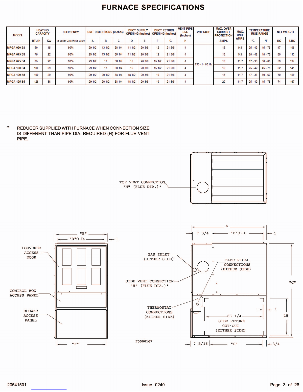
Furnace Specifications . . . . . . . . . . . . . . . . . . . . . . . . . . . . . . . 3
Introduction . . . . . . . . . . . . . . . . . . . . . . . . . . . . . . . . . . . . . . . 6
Location/Placement . . . . . . . . . . . . . . . . . . . . . . . . . . . . . . . . . . 6
Air for Combustion & Ventilation . . . . . . . . . . . . . . . . . . . . . . . . 8
Ducting . . . . . . . . . . . . . . . . . . . . . . . . . . . . . . . . . . . . . . . . . . 11
Venting . . . . . . . . . . . . . . . . . . . . . . . . . . . . . . . . . . . . . . . . . . 12
Electrical Connections . . . . . . . . . . . . . . . . . . . . . . . . . . . . . . . . 15
RETAIN THESE INSTRUCTIONS FOR FUTURE REFERENCE
Gas Connections . . . . . . . . . . . . . . . . . . . . . . . . . . . . . . . . . . . 15
Theory of Operation . . . . . . . . . . . . . . . . . . . . . . . . . . . . . . . . . 17
Start-Up Operation & Checkout . . . . . . . . . . . . . . . . . . . . . . . . . 18
Sequence of Operation . . . . . . . . . . . . . . . . . . . . . . . . . . . . . . . 22
Servicing The Furnace . . . . . . . . . . . . . . . . . . . . . . . . . . . . . . . 23
Trouble Shooting Guide . . . . . . . . . . . . . . . . . . . . . . . . . . . . . . . 25
Wiring Diagram . . . . . . . . . . . . . . . . . . . . . . . . . . . . . . . . . . . . . 26
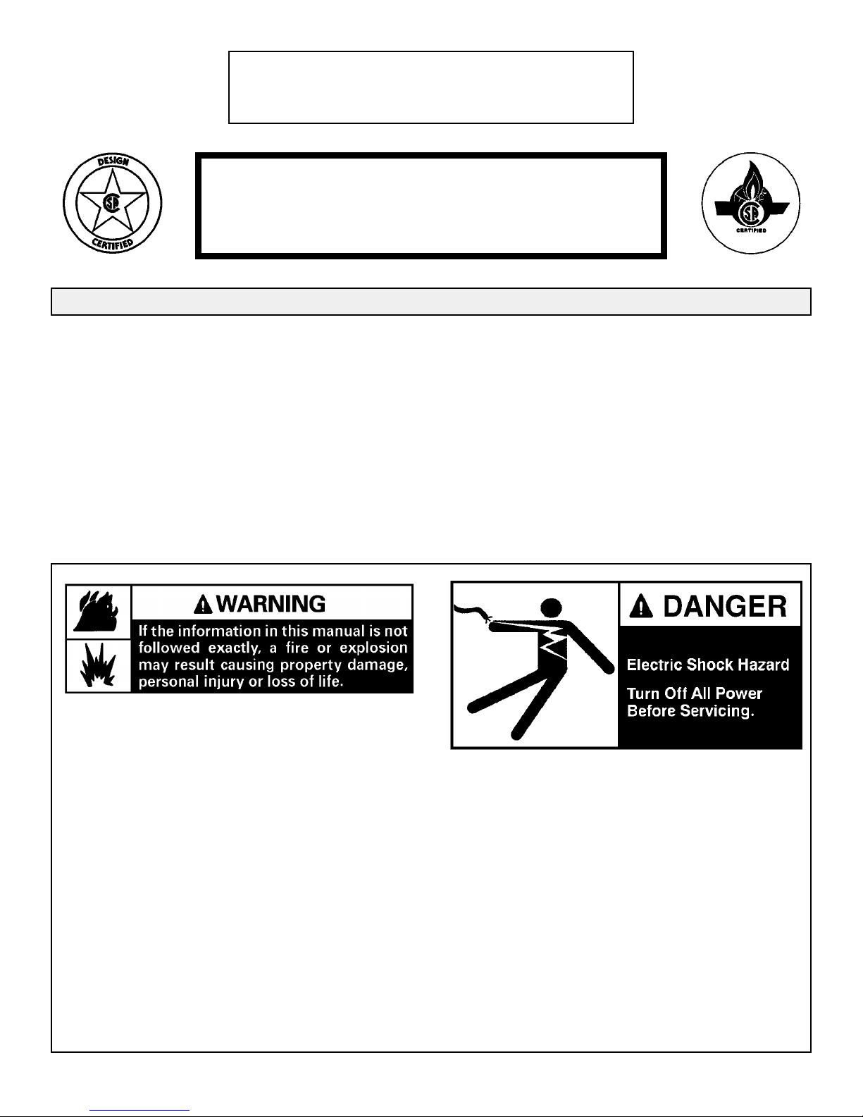
Do not store or use gasoline or other
flammable vapors and liquids in the
WHAT TO DO IF YOU SMELL GAS:
vicinity of this or any other appliance.
• Do not try to light any appliance.
Installation and service must be performed
by a qualified installer, service agency or
the gas supplier. Installation by an
unqualified person may lead to equipment
damage and/or a hazardous condition
which may cause bodily injury and harm
and, as such, at the sole discretion of the
manufacturer, the entire warranty may be
• Extinguish any open flame.
• Do not touch any electrical switch; do
not use any phone in your building.
• Immediately call your gas supplier from
a neighbor's phone. Follow the gas
supplier's instructions.
• If you cannot reach your gas supplier,
call the fire department.
voided and be of no further force and
effect.
20541501 Issue 240 Page 1 of 26
Page 4

SAFETY
The following is a list of safety precautions and their locations in this manual.
These safety rules and precautions must be followed when installing this furnace.
1. Use only with type of gas approved for this furnace. Refer to the furnace rating
plate.
2. Install this furnace only in a location and position as specified in The
Location/Placement Section on page 6 of these instructions.
3. Provide adequate combustion and ventilation air to the furnace space as
specified in Air for Combustion and Ventilation section on page 8 of these
instructions.
4. Combustion products must be discharged outdoors. Connect this furnace to an
approved vent system only, as specified in Venting on page 12 of these
instructions.
5. Never test for gas leaks with an open flame. Use a commercially available
soap solution made specifically for the detection of leaks to check all
connections, as specified in The Gas Connection section on page 16 of these
instructions.
6. Always install furnace to operate within the furnace's intended temperature-rise
range with a duct system which has an external static pressure within the
allowable range, as specified in Furnace Specifications on page 3 of these
instructions. See furnace rating plate.
7. When a furnace is installed so that supply ducts carry air circulated by the
furnace to areas outside the space containing the furnace, the return air shall
also be handled by duct(s) sealed to the furnace casing and terminating outside
the space containing the furnace. See page 11 for Ducting.
8. A gas-fired furnace for installation in a residential garage must be installed as
specified in The Location / Placement section on page 7 of these instructions.
9. The furnace is not to be used for temporary heating of buildings or structures
under construction. As noted on page 6 under Introduction.
20541501 Issue 0240 Page 2 of 26
Page 5
Page 6
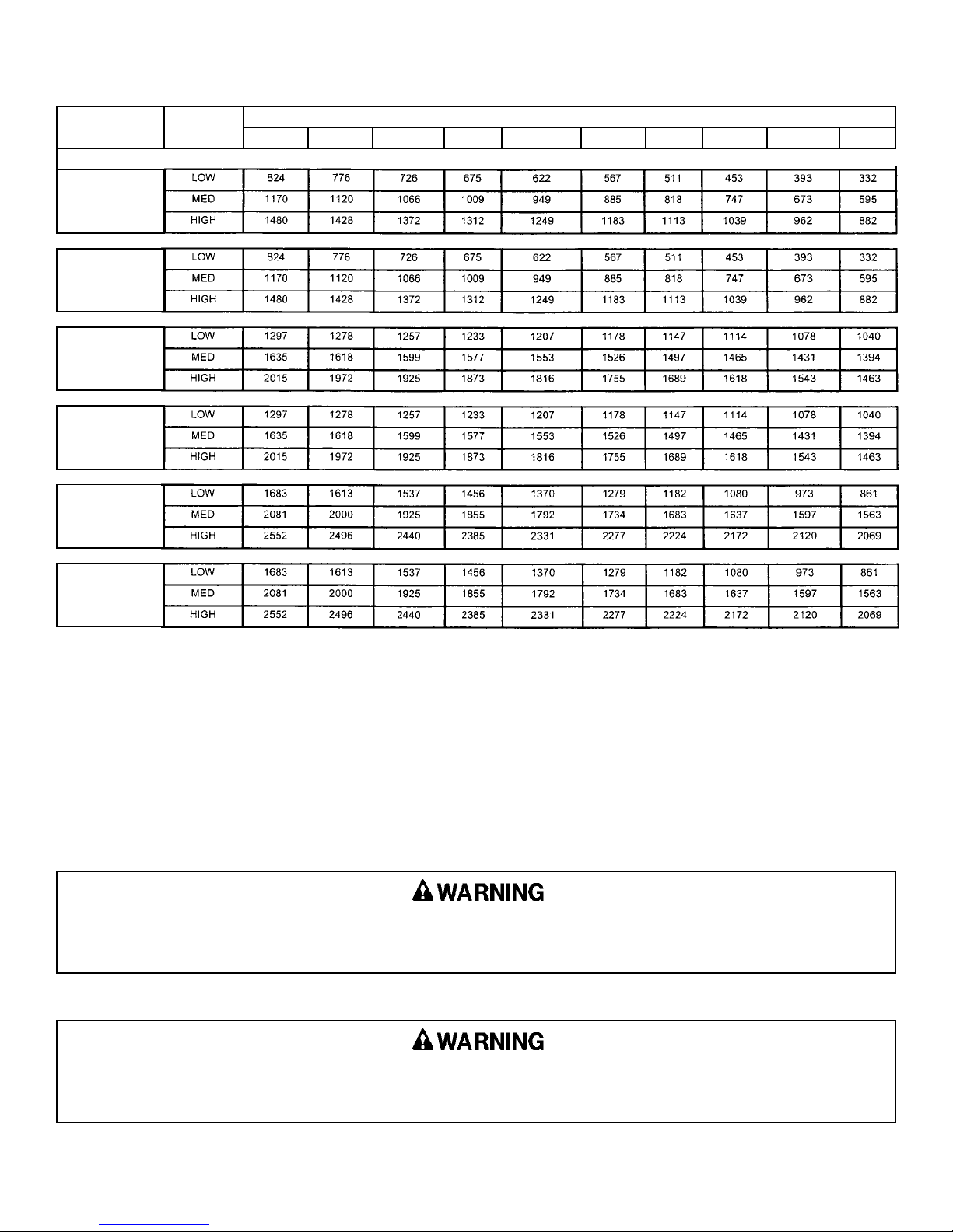
FURNACE BLOWER SPECIFICATIONS AND AIR FLOW DATA
BLOWER
SYSTEM
MPGA050B3
(10X6 WHEEL)
(1/3HP MOTOR)
MPGA075B3
(10X6 WHEEL)
(1/3HP MOTOR)
MPGA075B4
(12X9 WHEEL)
(1 HP MOTOR)
MPGA100B4
(10X9 WHEEL)
(1 HP MOTOR)
MPGA100B5
(12X9 WHEEL)
(1 HP MOTOR)
BLOWER
SPEED
EXTERNAL STATIC (IN. W.C.)
0.1 0.2 0.3 0.4 0.5 0.6 0.7 0.8 0.9 1.0
MPGA125B5
(12X12 WHEEL)
(1 HP MOTOR)
NOTES:
1. Air flow values in cubic feet per minute (CFM).
2. Data taken without filters in place or A/C evaporator in place.
When operating the furnace in the heating mode, the static pressure and the temperature rise (supply air temperature
minus return air temperature) must be within those limits specified on the rating label. Failure to follow this warning
could lead to severe furnace damage.
Turn OFF all gas and electrical power to furnace before performing any maintenance or service on unit. (Unless
specific test requires gas and electrical supplies.) Failure to take this precaution may result in personal injury due
to electrical shock or uncontrolled gas leakage.
20541501 Issue 0240 Page 4 of 26
Page 7
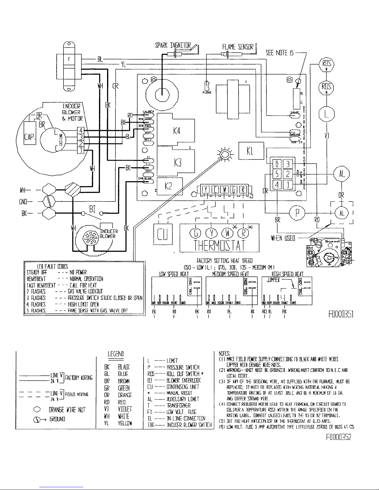
FURNACE WIRING SPECIFICATIONS
20541501 Issue 0240 Page 5 of 26
Page 8
The furnace cabinet must have an uninterrupted or unbroken electrical ground to minimize personal injury if an
electrical fault should occur. The unit must also be electrically grounded in accordance with local codes, or in the
absence of local codes, with the latest edition of the (U.S.) National Electrical Code ANSI/NFPA No. 70 or CSA
Standard C22.1; Part 1 Canadian Electrical Code, if an external electrical source is utilized. DO NOT use gas piping
as an electrical ground.
INTRODUCTION
This furnace is design certified by CSA International as a Category I furnace using air from inside the structure for
combustion.
It is shipped as a packaged unit, complete with burners and controls, and requires a line voltage (115V) connection to
the junction box, a thermostat hook-up as per the wiring diagram and a gas line connection. This furnace can be installed
in either upflow, downflow or horizontal airflow positions. The design of this furnace is NOT CSA Certified for
installation in recreation vehicles, in manufactured (mobil) homes, outdoors or for temporary construction heating.
This furnace has been designed to interface with split system cooling equipment (approved by a nationally recognized
testing laboratory) so as to provide "year round air conditioning". The blower has been sized for both heating and cooling
and the furnace controls include a cooling fan relay.
The furnace installation must conform with local building codes or in the absence of local codes, with the latest edition
of the (U.S.) National Fuel Gas Code ANSI Z223.1 (NFPA-54) or Canadian Natural Gas and Propane Installation Codes
CSA B149.1.
For complete information on installation standards consult the (U.S.) National Fuel Gas Code, obtainable from the
National Fire Protection Association, Inc., Batterymarch Park, Quincy, MA 02269 or the American Gas Association, 1515
Wilson Boulevard Arlington, VA 22209 or the Canadian installation codes obtainable from Canadian Standards Association,
178 Rexdale Boulevard, Etobicoke, Ontario, Canada M9W 1R3.
This furnace is designed for minimum continuous return-air temperature of 60°F dB or intermittent operation down to
55°F dB such as when used with a night setback thermostat. Return-air must not exceed a maximum continuous
temperature of 85°F dB.
These instructions are written for individual residential installation only. For multi-unit installation or
commercial applications, please contact manufacturer for recommendations.
LOCATION / PLACEMENT
Site Selection: This furnace may be located in an attic, closet, basement, crawl space, alcove or suspended from the
ceiling of a utility room or basement. Select a location that will meet all requirements for safety,
clearances, ventilation and combustion air, ductwork design, gas piping, electrical wiring and venting.
Clearances: The following minimum clearances, or greater, must be provided between the furnace and adjacent
construction.
TABLE 1 MINIMUM INSTALLATION CLEARANCES
"UPFLOW" POSITION "DOWNFLOW" POSITION "HORIZONTAL" POSITION
Suitable for alcove or closet
installation† on combustible
flooring at minimum
clearance from adjacent
construction not less than
the following:
Top Sides Back Front Vent
2" 1" 1" 6" 6" with single wall vent
2" 1" 1" 3" 1" with B1 vent
† For closet installation see Air for Combustion and Ventilation.
Suitable for alcove or closet installation† on noncombustible flooring at minimum clearance from
adjacent construction not less than the following:
* Installation on combustible flooring only when
installed on special base (see model & rating label
for proper special base).
Suitable for attic, alcove or closet installation† on
combustible flooring at minimum clearance from
adjacent construction not less than the following:
* Line contact only permissible between lines
formed by intersection of the top and two sides of
the furnace jacket and building joist, studs, or
framing.
20541501 Issue 0240 Page 6 of 26
Page 9
Failure to comply with all of the clearances will
create a fire hazard.
The furnace should also be located as near to the
center of the air distribution system as possible, and
should be installed level.
This furnace may be installed on non-combustible
flooring or on wood flooring, however, it must not be
installed directly on carpeting, tile or any other
combustible material. In the downflow position, it must
be installed on non-combustible flooring or on the special
base listed on the rating label.
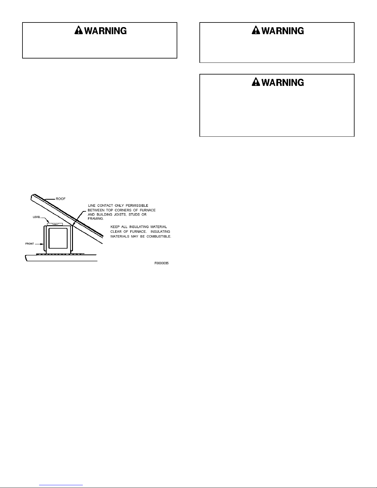
In a horizontal position, line contact is only
permissible between lines formed by the intersection of
the furnace top, the front and back sides, and building
joists, studs or framing (See Figure 1).
Figure 1
HORIZONTAL LINE CONTACT
Do not place combustible material on the furnace
jacket. Failure to comply with this warning will
create a fire hazard.
This furnace is not watertight and is not designed
for outdoor installation. This furnace shall be
installed in such a manner as to protect the
electrical components from water. Outdoor
installation would lead to a hazardous electrical
condition and to premature furnace failure.
Furnace must not lean back. It must be level or
tilt up to 2° to the front. (See Figure 1.)
A clearance of at least 30" should be provided at the
front of the unit for servicing. For attic installations, the
passageway and servicing area adjacent to the furnace
should be floored.
If the furnace is to be installed in a crawl space,
consult local codes. (Use of a concrete pad 1" to 2" thick
is recommended.)
If the furnace is to be suspended from the ceiling, it
will be necessary to use steel pipe straps around each
end of the furnace. These straps should be attached to
the furnace with sheet metal screws and to the rafters
with bolts. The furnace may also be suspended by using
an angle iron frame bolted to the rafters. (See Table on
page 3 for size and weight of furnace.) Care must be
taken to allow for service access.
If a furnace is to be installed in a residential garage,
it must be installed so the burners and the ignition source
are located not less than 18" above the floor and the
furnace must be located or protected to avoid physical
damage by vehicles.
20541501 Issue 0240 Page 7 of 26
Page 10
AIR FOR COMBUSTION AND VENTILATION
Contaminated Combustion Air:
This furnace is not to be installed in a structure
defined as having contaminated combustion air. Allowing
exposure to substances containing chlorine or fluoride
could harm the furnace and void the warranty.
Substances to avoid include, but are not limited to:
• Permanent wave solutions
• Chlorinated waxes and cleaners
• Chlorine based swimming pool chemicals
• Water softening chemicals
• De-icing salts or chemical
• Carbon tetrachloride
• Halogen type refrigerants
• Cleaning solvents (such as perchloroethylene)
• Printing inks, paint removers, varnishes, etc.
• Hydrochloric acid
• Cements and glues
• Antistatic fabric softeners for clothes dryers
• Masonry acid washing materials
• Unrefined gases
Contaminated combustion air may cause premature
failure of the heat exchanger that may lead to a
hazardous condition and/or bodily harm, or loss of
life.
Adequate Ventilation and Combustion Air:
This section is provided to give guidelines for the
introduction of air for ventilation and combustion air. The
total quantity of air provided to the installation area must
equal the requirements of all gas appliances in the area.
Adequate facilities for providing air for combustion
and ventilation must be provided in accordance with the
latest edition of the National Fuel Gas Code ANSI
Z223.1/NFPA54 or CSA B149.1 Natural Gas and Propane
Installation Codes, or applicable provisions of the local
building codes.
The furnace shall be installed in a location in which
the facilities for ventilation permits satisfactory combustion
of gas, proper venting and maintenance of ambient
temperature at safe limits under normal conditions of use.
The furnace shall be located so as not to interfere with
proper circulation of air.
In addition to air needed for combustion, ventilation in
the form of process air must be provided as required for:
cooling of equipment or material, controlling dew point,
heating, drying, oxidation or dilution, safety exhaust and
odor control. Air must be supplied for ventilation,
including all air required for comfort and proper working
conditions for personnel.
For purposes of this instruction the following
definitions apply:
Confined Space: A space whose volume is less
than 50 cubic feet per 1000
Btu/hr of the aggregate input
rating of all appliances installed
in that space.
Unconfined Space: A space whose volume is not
less than 50 cubic feet per 1000
Btu/hr of the aggregate input
rating of all appliances installed
in that space. Rooms
communicating directly with the
space in which the appliances
are installed, through openings
not furnished with doors, are
considered a part of the
unconfined space.
If the installation area meets the definition of
"Unconfined Space" and does not have additional air
requirements as described, the furnace may be installed
without making special provisions for combustion and
ventilation air.
Whenever this furnace is installed in an area along
with one or more gas appliances, the total Btu/hr
input of all appliances must be included when
determining the free area requirements for
combustion and ventilation air openings.
Do not block the combustion or ventilation air
openings in the furnace. Any blockage will result in
improper combustion and may result in a fire
hazard or unsafe condition.
20541501 Issue 0240 Page 8 of 26
Page 11

If ventilation and/or combustion air must be supplied to the "Confined Space" from inside the building structure, two
permanent openings to an additional room of sufficient volume as to combine the volumes of the spaces to meet the
criteria for an "Unconfined Space" must be created. Each opening must have a free area of not less than one square
inch per 1000 Btu per hour of total input of all appliances within the "Confined Space" (but not less than 100 square
inches). These openings must be located 12 inches from the top and bottom of the furnace area respectively and must
be at least 3 inches long on the smaller side of the opening (See Figure 2). Neither opening can be blocked at any time.
Figure 2 CONFINED SPACE / INDOOR AIR
TOTAL INPUT
(Btuh)
40,000
60,000
80,000
100,000
120,000
140,000
160,000
EXAMPLE:
50,000 Btuh Furnace & 10,000 Btuh Water
Heater = 60,000 Btuh Total Input = 12"
Dia. Round Duct.
MIN. FREE AREA
(Sq. In.)
100
100
100
100
120
140
160
ROUND DUCT
(Dia. In.)
12
12
12
12
13
14
15
If ventilation and/or combustion air must be supplied to the "Confined Space" from outside the building structure,
two permanent openings to the outdoors must be created. Each opening must have a free area of not less than one
square inch per 4000 Btu per hour of total input of all appliances within the "Confined Space". These openings must
be located 12 inches from the top and bottom of the furnace area respectively (See Figures 3, 4, and 5). Neither
opening can be blocked at any time.
Figure 3 CONFINED SPACE / OUTDOOR AIR
20541501 Issue 0240 Page 9 of 26
TOTAL INPUT
(Btuh)
40,000
60,000
80,000
100,000
120,000
140,000
160,000
EXAMPLE:
50,000 Btuh Furnace & 10,000 Btuh Water
Heater = 60,000 Btuh Total Input = 5" Dia.
Round Duct.
MIN. FREE AREA
(Sq. In.)
10
15
20
25
30
35
40
ROUND DUCT
(Dia. In.)
4
5
5
6
6
7
8
Page 12
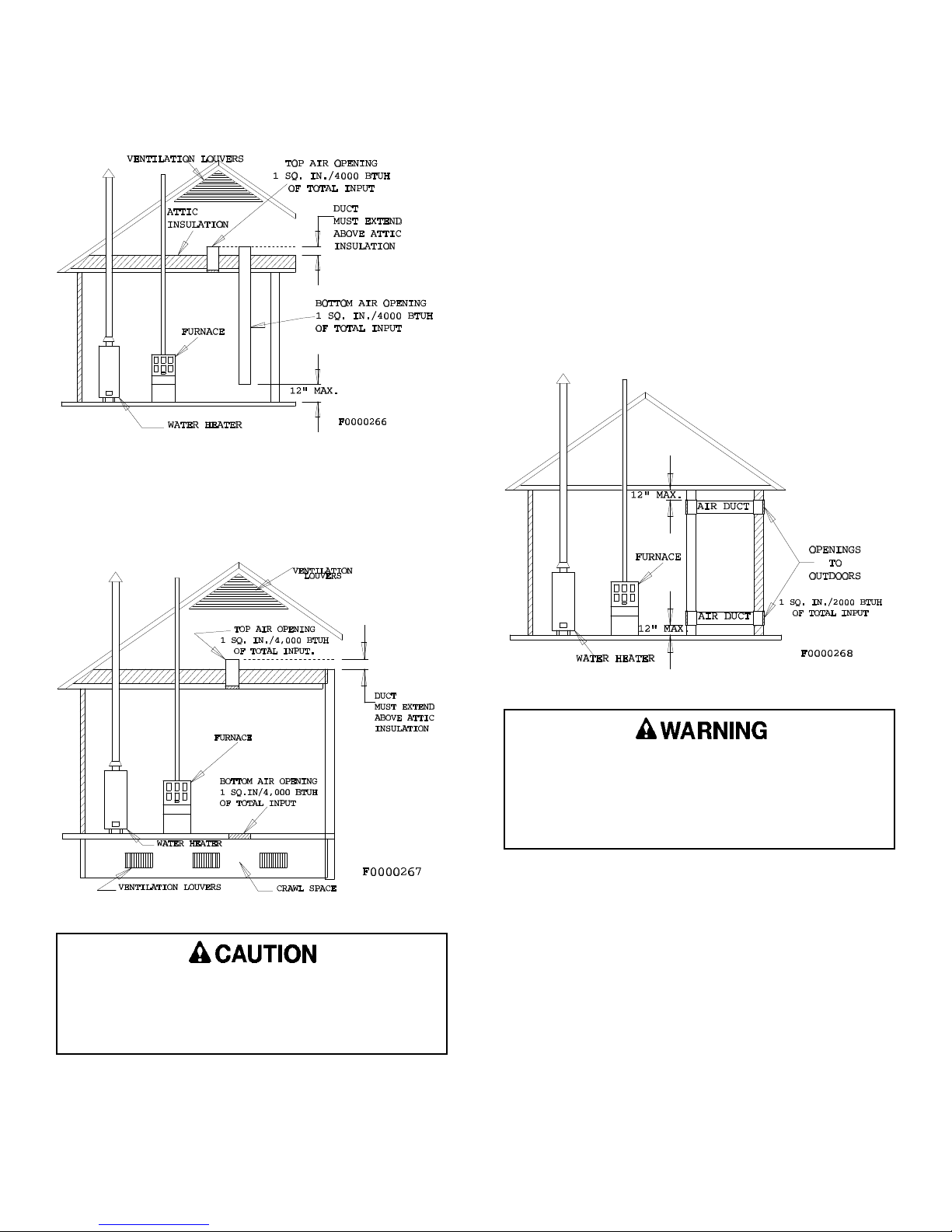
Figure 4
Figure 5
CONFINED SPACE / OUTDOOR AIR
FROM ATTIC
CONFINED SPACE / OUTDOOR AIR
FROM ATTIC & CRAWL SPACE
When horizontal ducts are used to supply air from the
outdoors, they must be of the same cross sectional area
as the free area of the openings to which they connect.
The minimum dimension of rectangular air ducts must not
be less than 3 inches. Each opening must have a free
area of not less than one square inch per 2,000 Btu per
hour of total input of all appliances within the "Confined
Space". These openings must be located 12 in. from the
top and bottom of the furnace area. Neither opening can
be blocked at any time (See Figure 6).
Figure 6
CONFINED SPACE / OUTDOOR
AIR THROUGH HORIZONTAL DUCTS
Furnaces installed with combustion air drawn from
a heated space which includes exhaust fans,
fireplaces, or other devices that may produce a
negative pressure should be considered confined
space installations.
For an attic installation it is important to keep
insulation 12" or more away from any furnace
openings. Some types of insulating materials may
be combustible.
20541501 Issue 0240 Page 10 of 26
Page 13

DUCTING
The proper sizing of warm air ducts is necessary to insure satisfactory heating operation. Ductwork should be in
accordance with the latest editions of (U.S.) NFPA-90A (Air Conditioning Systems) and NFPA-90B (Warm Air Heating
and Air Conditioning Systems) or Canadian equivalent.
Ductwork Recommendation:
The supply duct work should be attached to the
flanged opening provided at the discharge end of the
furnace. See page 3 "Furnace Specificatons" for the
dimensions of this opening.
A left, right, or bottom return air opening must be
used as determined by the layout of the installation. An
externally mounted air filter is required.
This furnace has a two piece bottom panel. For
bottom or end duct return, remove the back portion of the
bottom panel by removing the four (4) screws - two (2) on
each side toward the back of the furnace (See Figure 7).
Tilt furnace toward the front, the back portion of the panel
will drop down. Then the back portion can be removed
by pulling toward the back of the furnace.
Figure 7
BOTTOM PANEL REMOVAL
Knockouts are provided on both sides of the furnace
to facilitate the cutout required to the return air ductwork.
Furnace cutouts must be the full size specified by the
corner markers. Undersized cutouts will adversely
affect the airflow capability of the furnace and could
cause overheating of the heat exchanger.
The following recommendations should be followed
when installing the ductwork:
1. Install locking-type dampers in all branches of the
individual ducts to balance out the system. Dampers
should be adjusted to impose the proper static at the
outlet of the furnace.
2. Noncombustible flexible duct connectors are
recommended to connect both the supply and return
ducts to the furnace.
3. In cases where the return air grille is located close to
the blower inlet, there should be at least one 90° air
turn between blower and return grille. Further
reduction in sound can be accomplished by installing
acoustical air turning vanes and/or lining the inside of
the duct with acoustical material.
4. It is recommended that the supply duct be provided
with a removable access panel. This opening shall
be accessible when the furnace is installed and shall
be of such a size that the heat exchanger can be
viewed for possible openings using light assistance or
a probe can be inserted by sampling the air stream.
The access panel shall be designed so as to prevent
leaks when locked in position. If an air conditioning
coil is installed, the access panel to the coil can be
used for this purpose.
When supply ducts carry air circulated by the
furnace to areas outside the spaces containing the
furnace, the return air shall also be handled by a
duct sealed to the furnace casing and terminating
outside the space containing the furnace. Incorrect
ductwork termination and sealing will create a
hazardous condition that could lead to bodily harm.
Air openings, intake and outlet pipes, return air
grilles and warm air registers must not be
obstructed.
To Convert to Downflow Position:
1. Convert the combustion blower to side flue exit, as
outlined on page 14.
2. Install proper special base per Table 2 for installation
on combustible flooring (follow instructions supplied
with special base).
3. It is recommended that the return air be connected to
the bottom panel of the furnace when it is installed in
the downflow position.
NOTE: SPECIAL SUB-BASE NOT REQUIRED WHEN
FURNACE IS MOUNTED ON A METAL CASED
EVAPORATOR COIL.
Table 2
SPECIAL BASE INSTALLATION
MODEL
MPGA050B3
MPGA075B3
MPGA075B4
MPGA100B4 20066502 68L78
MPGA100B5
MPGA100B5
NOTE: Installation on combustible flooring only when
SPECIAL BASE
NUMBER
20066501 68L77
20066503 68L79
CAT. NO.
installed on one of the above listed special bases
or as identified on the furnace model and rating
label.
20541501 Issue 0240 Page 11 of 26
Page 14

Filters:
Air filters must be used in every installation. For side
return installations, air filters must be installed external to
the furnace casing. An external filter rack kit with filter
(parts No. 20069901 or Cat. No. 68L75 12 / 15½" x 25"
sizes and 20069902 or Cat. No. 68L76 for 15½" / 19" x
25" sizes) is available as an optional accessory.
For bottom (end) return installations, the above
optional external rack may be used, if the unit was not
provided with a internal filter. Minimum filter size and
suggested filter materials are shown in Table 3. (If
different type filter is used, it must be an equivalent high
airflow capacity.)
2. In parallel flow installation, dampers must be provided
to direct air over the furnace heat exchanger when
heat is desired and over the cooling when cooling is
desired.
IMPORTANT: The dampers should be adequate to
prevent cooled air from entering the
furnace, and if manually operated, must
be equipped with means to prevent
operation of either the cooling unit or
furnace unless the damper is in the full
cool or full heat position.
Table 3 EXTERNAL FILTER RACK SIZE
MODEL
050-3
075-3
075-4
100-3 15 ½ X 25 15 ½ X 25
100-5
125-5
SIDE
RETURN
15 ½ X 25 12 X 25
15 ½ X 25 19 X 25
BOTTOM/END
RETURN
When installing the furnace with cooling equipment for
year round operation, the following recommendations
must be followed for series or parallel air flow:
1. In series flow applications, the coil is mounted after
the furnace in an enclosure in the supply air stream.
The furnace blower is used for both heating and
cooling airflow.
VENTING
Venting for the furnace must be to the outside and in
accordance with local codes or requirements of the local
utility. In the absence of local codes, venting must
conform to the applicable sections of the latest edition of
the (U.S.) National Fuel Gas Code ANSI Z223.1/NFPA54,
and/or CSA B149.1 Natural Gas and Propane Installation
Codes, and the vent manufacturers instructions.
This furnace is CSA International certified as a
Category I forced air appliance and can not be vented
into a vent system with any Category II, III or IV
appliance. It must be vented vertically, or nearly
vertically, unless installed with a listed mechanical venter
in accordance with horizontal venting instructions. It must
not be connected to any portion of a mechanical draft
system operating under positive pressure
The 3" (in.) to 4" (in.) vent adaptor coupling (supplied
with unit) MUST BE USED. It must be connected directly
to the outlet of the combustion blower using a field
supplied corrosion resistant sheet metal screw (See
Figure 8).
The coil MUST be installed on the air discharge
side of the furnace. Under no circumstances
should the air flow be such that cooled, conditioned
air can pass over the furnace heat exchanger. This
will cause condensation in the heat exchanger and
possible failure of the heat exchanger that could
lead to a fire hazard and/or hazardous conditions
that may lead to bodily harm. Heat exchanger
failure due to improper installation will not be
covered by warranty.
Figure 8
VENT ADAPTOR MOUNTING
Pre-Installation Vent System Inspection:
Before this furnace is installed, it is highly
recommended that any existing vent system be
completely inspected.
For a chimney or "B" vent, this should include the
following:
1. Inspection for any deterioration in the chimney or "B"
vent. If deterioration is discovered, the chimney must
20541501 Issue 0240 Page 12 of 26
Page 15

be repaired or the "B" vent must be replaced.
2. Inspection to ascertain that the vent system is clear
and free of obstructions. Any blockage must be
cleared before installing this furnace.
3. Cleaning the chimney or "B" vent if previously used
for venting a solid fuel burning appliance or fireplace.
4. Confirming that all unused chimney or "B" vent
connections are properly sealed.
5. Verification that the chimney is properly lined and
sized per the applicable codes.
Masonry Chimney:
This furnace can be common vented into an existing
tile lined masonry chimney provided:
1. The chimney is currently serving at least one
drafthood equipped appliance.
2. The vent connectors and chimney are sized in
accordance with the applicable sections of the (U.S.)
National Fuel Gas Code ANSI Z223.1/NFPA54,
and/or CSA B149.1 Natural Gas and Propane
Installation Codes.
This furnace must NOT vented ALONE into an
existing masonry chimney (either tile lined or unlined)
unless the chimney is also lined with either a type B vent
system or a listed single wall, metal lining system. Both
of these systems must be sized in accordance with the
applicable sections of the (U.S.) National Fuel Gas Code
ANSI Z223.1/NFPA54, and/or CSA B149.1 Natural Gas
and Propane Installation Codes.
Before venting this furnace into a chimney, check the
chimney for deterioration and repair if necessary. This
furnace must not be vented into a chimney serving a
separate appliance designed to burn solid fuel. Type"B"
vent connectors must be used on all installations and it
must be sized per the applicable sections of the (U.S.)
National Fuel Gas Code ANSI Z223.1/NFPA54, and/or
CSA B149.1 Natural Gas and Propane Installation Codes.
Type "B" Vent:
The furnace is also approved for use with a "B" vent
that terminates through the roof. Refer to the applicable
sections of the (U.S.) National Fuel Gas Code ANSI
Z223.1/NFPA54, and/or CSA B149.1 Natural Gas and
Propane Installation Codes for proper sizing and set-up
of this furnace with "B" vent for a dedicated vent system
or a common vented system.
Horizontal Venting:
This furnace is design certified by CSA International
for horizontal venting through an outside wall by use of
one of the following auxiliary draft inducer kits:
Table 4 AUXILIARY DRAFT INDUCERS
Vent Kit MFR Model * Furnace Input
Field Controls Co.
Tjernlund Products Inc.
* See rating label on this furnace for input
Vent Length: Max. 60 ft. - Min. 12 ft.
Follow instructions included with venting kit for proper installation and setup.
SWG-4G
SS1 OR SS1C
GPAK-J 50000, 75000 or 100000
GPAK-1 100000 or 125000
Vent Diameter: 4 in.
50000, 75000, 100000 or
125000
50000, 75000, 100000 or
125000
Location Requirements for Horizontal Venting:
Locate the vent terminal adhering to the following
minimum clearances:
1. Vent terminal must be located at least one (1') foot
above the grade or at least one (1') foot above the
normal expected snowfall.
2. Avoid installing vent terminal above public walkways.
If this is not possible, install the terminal at least
seven (7') feet above the walkway.
3. Vent terminal should be at least four (4') feet to the
side of and at least one (1') foot above doors and
windows.
4. Vent terminal should be at least three (3') feet above
any forced air inlet located within ten (10') feet.
5. Vent terminal should be located at least six (6') feet
from the combustion air intake of another appliance.
6. Vent terminal should be located at least four (4') feet
above any electric or gas meters, regulators, and
relief equipment.
General Venting Requirements:
This furnace may be common vented only with other
Category I appliances. Common venting is allowed as
permitted by National and/or local codes. Refer to the
applicable sections of the (U.S.) National Fuel Gas Code
ANSI Z223.1/NFPA54, and/or CSA B149.1 Natural Gas
and Propane Installation Codes for proper sizing and set
up.
The vent must be terminated with a listed vent cap or
roof assembly. This venting must be installed in
accordance with the vent manufacturer's instructions and
be in accordance with all local codes and/or National
Codes. Follow Figure 9 for vent exit options.
The following requirements are provided for a proper
venting system:
1. Be sure that the chimney flue is clear of any dirt or
debris.
2. Be sure that the chimney is not servicing an open
fireplace.
3. Never reduce the pipe size below the outlet size of
the furnace without checking the applicable sections
of the (U.S.) National Fuel Gas Code ANSI
Z223.1/NFPA54, and/or CSA B149.1 Natural Gas and
Propane Installation Codes.
20541501 Issue 0240 Page 13 of 26
Page 16

4. All pipe should be supported using the proper clamps
and/or straps. These supports should be at least
every four (4') feet.
5. All horizontal runs of pipe should have at least a 1/4"
(in.) per foot of upward slope from the furnace to the
vent terminal.
6. All runs of pipe should be as short as possible with
as few turns as possible.
7. Seams should be tightly joined and checked for
leaks.
8. The flue pipe must not extend into the chimney but
be flush with the inside wall.
9. The chimney or vent pipe must extend at least three
(3') feet above the highest point where it passes
through a roof of a building and at least two (2') feet
higher than any portion of a building within a
horizontal distance of ten (10') feet. It shall also
extend at least five (5') feet above highest connected
equipment flue collar.
Figure 9
VENT EXIT OPTIONS
combustion blower adaptor plate to the flue collector
box, taking care to support the blower assembly so
that it does not fall.
4. Rotate the blower 90° (degrees) clockwise, so that
the outlet of the blower is pointing toward the right
side panel of the furnace.
5. Insure that the gasket is in place between the blower
adaptor plate and the flue collector box. Reattach the
blower assembly to the flue collector box, using the
four (4) screws removed in step 3. Be sure that the
screws are properly tightened and that the gasket
seals the plate to the box.
6. Reconnect the pressure switch tubing to the
combustion blower.
7. (Optional) Install vent pipe guard.
Kit Number 20284801.
Figure 10
VENT PIPE GUARD KIT
10. The 3" to 4" vent adaptor coupling must be used to
connect to the combustion blower outlet. It must be
installed directly to the combustion blower outlet (See
Figure 8).
To Convert to Side Flue Exit:
1. Remove the louver door from the furnace. (Be sure
the side vent exit knock-out is removed from the right
side panel of the cabinet. See Figure 9.)
2. Disconnect the pressure switch tubing from the
combustion blower.
3. Remove the four (4) screws that secure the
For Horizontal Positions:
It is not necessary to reposition any of the
components of the furnace in order to install it in either
horizontal position. As outlined above, it is permissible to
use the side vent exit for the horizontal-left position, if
desired.
Checking For Vent Oversizing:
If this furnace is replacing a furnace that is attached
to a venting system serving other appliances, the venting
system is likely to be too large to properly vent all of the
attached appliances. An improperly sized venting system
can lead to condensation, leakage, or spillage.
20541501 Issue 0240 Page 14 of 26
Page 17

CARBON MONOXIDE POISONING HAZARD
Failure to follow the steps outlined below for each appliance connected to the venting system being placed
into operation could result in carbon monoxide poisoning or death.
The following steps shall be followed for each appliance connected to the venting system being placed into
operation, while all other appliances connected to the venting system are not in operation:
1. Seal any unused openings in the venting system.
2. Inspect the venting system for proper size and horizontal pitch, as required in the National Fuel Gas Code,
ANSI Z223.1/NFPA 54 or the CSA B149.1, Natural Gas and Propane Installation Codes and these
instructions. Determine that there is no blockage or restriction, leakage, corrosion and other deficiencies
which could cause an unsafe condition.
3. As far as practical, close all building doors and windows and all doors between the space in which the
appliance(s) connected to the venting system are located and other spaces of the building.
4. Close fireplace dampers.
5. Turn on clothes dryers and any appliance not connected to the venting system. Turn on any exhaust fans,
such as range hoods and bathroom exhausts, so they are operating at maximum speed. Do not operate
a summer exhaust fan.
6. Follow the lighting instructions. Place the appliance being inspected into operation. Adjust the thermostat
so appliance is operating continuously.
7. Test for spillage from draft hood equipped appliances at the draft hood relief opening after 5 minutes of main
burner operation. Use the flame of a match or candle.
8. If improper venting is observed during any of the above tests, the venting system must be corrected in
accordance with the National Fuel Gas Code, ANSI Z223.1/NFPA 54 and/or CSA B149.1, Natural Gas and
Propane Installation Codes.
9. After it has been determined that each appliance connected to the venting system properly vents when
tested as outlined above, return doors, windows, exhaust fans, fireplace dampers and any other gas-fired
burning appliance to their previous conditions of use.
ELECTRICAL CONNECTIONS
When installed, the furnace must be electrically
grounded in accordance with local codes or, in the
absence of local codes, with the (U.S.) National Electrical
Codes, ANSI/NFPA 70 or CSA Standard C22.1; Part 1
Canadian Electrical Code. For proper installation refer to
furnace rating label for electrical ratings and for the field
wiring of this unit refer to furnace wiring specifications on
page 5 or alternately from the wiring diagram on page 28.
In all instances, other than wiring for the thermostat, the
wiring to be done and any replacement of wire shall
conform with the temperature limitation for Type T wire
[63°F rise (35°C)].
The electrical connections and the thermostat
connections are made at the openings on either side
panel of the unit in the control box area. Either side may
be used as convenient, but the provided hole plugs must
be inserted in the unused holes.
The control system depends on the correct polarity of
the power supply. Connect "Hot" (H) wire and "Ground"
(G) wire as shown in furnace wiring specification on
wiring diagram. Use reference Table on page 3 (Furnace
Specifications), for over current protection, max unit amp
rating and wire size. Use copper wire only for 115Vsupply service to unit. When replacing any original
internal wiring, use only 105°C, 16 AWG copper wire.
Instructions for wiring the thermostat are packed in
the thermostat (field supplied) box. Make the thermostat
connections as shown in furnace wiring specifications at
the 24-volt terminal board located in the control box.
When installing optional accessories to this appliance,
follow the manufacturer's installation instructions included
with the accessory.
The unit cabinet must have an uninterrupted or
unbroken electrical ground to minimize personal
injury if an electrical fault should occur. This may
consist of electrical wire or approved conduit when
installed in accordance with existing electrical
codes. Do not use gas piping as an electrical
ground. Failure to follow this warning can result in
an electrical shock, fire, bodily harm, or loss of life.
20541501 Issue 0240 Page 15 of 26
Page 18

GAS CONNECTIONS
Gas piping shall be of such size and so installed as
to provide a supply of gas sufficient to meet maximum
demands without undue loss of pressure between the gas
meter and the furnace. It is recommended that the gas
line to the furnace shall be a separate line direct from the
meter, unless the existing gas line is of ample capacity.
Refer to gas pipe capacity table in the National Fuel Gas
Code ANSI Z223.1/NFPA54, and/or CSA B149.1 Natural
Gas and Propane Installation Codes.
If local codes allow the use of a flexible gas appliance
connector, always use a new listed connector. Do no use
a connector which has previously serviced another gas
appliance.
Use a joint compound (pipe dope) that is resistant to
the action of liquefied petroleum gases or any other
chemical constituents of the gases to be conducted
through the piping.
For proper furnace operation the maximum gas
supply pressure is 14" w.c. and the minimum gas
supply pressure is 4.5" w.c. - Natural (11" w.c. - LP)
as shown on rating label.
Before any system of gas piping is finally put into
service, it should be carefully tested to determine if it is
gas tight. Check all piping for leaks using soapy water
and a brush. The piping must stand a pressure of six (6)
inches of mercury (3 PSIG) for a period of ten (10)
minutes or as required by local authority.
Figure 11
GAS CONTROL PIPING
Figure 12
TYPICAL GAS SERVICE CONNECTION
FIRE OR EXPLOSION HAZARD
Failure to follow the safety warnings exactly
could result in serious injury, death or property
damage.
Never test for gas leaks with an open flame.
Use a commercially available soap solution made
specifically for the detection of leaks to check all
connections. A fire or explosion may result causing
property damage, personal injury or loss of life.
The furnace and its individual shutoff valve
must be disconnected from the supply piping
system during any pressure testing of that system
at test pressures in excess of 1/2 PSIG (3.5kPa or
14"w.c.).
The furnace must be isolated from the gas
supply piping system by closing its individual
manual shutoff valve during any pressure testing of
the gas supply piping system at pressures equal to
or less than 1/2 PSIG (3.5kPa or 14"w.c.). Failure
to follow the above procedures could lead to a
hazardous condition and bodily harm.
This furnace is manufactured for use with Natural gas
and must be converted using the proper LP conversion kit
for use with LP (Propane) gas. For LP (Propane) gas, a
tank regulator is required to reduce supply pressure to
12"-13"w.c. For manifold pressure see Table 6.
A main manual shut off valve must be used in the
gas piping. The shut off type and location must follow
local codes and should always be in an accessible but
protected location. In the absence of local codes the
recommended methods for installing the gas piping to the
furnace are shown in Figures 11 and 12.
The gas valve contains two threaded ports for a 1/8"
NPT tap in order to test incoming gas pressure and
outgoing manifold pressure (See Figure 13).
Many soaps used for leak testing are corrosive to
certain metals. Piping must be rinsed thoroughly
with clean water after leak check has been
completed.
Never use an open flame when testing for gas
leaks! Use of an open flame could lead to a fire or
explosion.
20541501 Issue 0240 Page 16 of 26
Page 19

THEORY OF OPERATION
20541501 Issue 0240 Page 17 of 26
Page 20

STARTUP AND OPERATIONAL CHECKOUT
Do not use this furnace as a construction heater.
Use of this furnace as a construction heater
exposes the furnace to abnormal conditions,
contaminated combustion air and the lack of air
filters. Failure to follow this warning can lead to
premature furnace failure and/or vent failure which
could result in a fire hazard and/or bodily harm.
The automatic gas valve controls the flow of gas to
the main burners. The ignition system control switch built
into the automatic valve body has 2 positions: "OFF" and
"ON" (Figure 13). To shut off gas manually:Rotate switch
from "ON" to "OFF" position. When in "OFF" position, the
main burners are extinguished.
This furnace is equipped with an automatic hotsurface ignition control and does not require the manual
lighting for furnace operation.
1. Be sure all electrical power is OFF.
2. Check all wiring using proper wiring diagram on
inside of the control box cover.
3. Turn ON the electrical power.
4. Set the gas control knob in the "ON" position.
5. Set the thermostat above room temperature.
6. The ignitor will spark and the main burner
will ignite.
Figure 14
TYPICAL FLAME APPEARANCE
(Main Burners)
Figure 13
GAS CONTROL DIAGRAM
Do not attempt to manually light the burners.
Failure to follow this warning can lead to electrical
shock that could result in bodily harm.
7. Recheck for leaks in the manual shut off valve, gas
control valve and gas connections using a soap
solution.
Never use an open flame when testing for gas
leaks! Use of an open flame could lead to a fire or
explosion.
Many soaps used for leak testing are corrosive to
certain metals. Piping must be rinsed thoroughly
with clean water after leak check has been
completed.
After the ductwork connections have been made, gas
piping and electrical wiring completed and the furnace
has been properly vented, the unit should be started and
adjusted for proper operation. Check off the following
steps as they are completed.
20541501 Issue 0240 Page 18 of 26
Manifold Pressure Adjustment:
Turn OFF the gas and electrical before
preceeding! Remove the manifold pressure tap pipe
plug from the gas valve (Figure 13 outlet pressure tap)
and install a pressure tap and connect it to a manometer.
Turn on the gas and electrical supplies, then measure the
manifold pressure with the furnace in operation.
Page 21

Remove the cap to access the screw for input
adjustment (Figure 13 Pressure Regulator). Turn
regulator-adjusting screw IN to increase pressure,
OUT to decrease pressure. Replace the cap. Measure
the manifold pressure.
For Natural gas, best results are obtained with a
manifold pressure of 3.2" to 3.5"w.c. For units that have
been converted to LP (Propane) gases, a manifold
pressure of 10"w.c. is necessary. After proper
adjustment, turn OFF gas, replace manifold pressure tap
pipe plug and turn ON gas.
At higher altitudes and varying heating valves,
manifold pressure or orifice changes maybe
required. Consult Tables 7 and 8 for appropriate
values. Failure to follow this warning could lead to
a hazardous furnace operating condition and result
in serious bodily injury or loss of life.
Determining Furnace Input - Natural Gas ONLY:
NOTE: Louvered access door of furnace must be in
place when checking gas input.
TABLE 5
Gas Rate (Cubic Feet per Hour)
TEST DIAL
Seconds for
One
Revolution
10 160 360 720
12 150 300 600
14 129 257 514
16 113 225 450
18 100 200 400
20 90 180 360
22 82 164 325
24 75 150 300
26 69 138 276
28 64 129 258
30 60 120 240
32 56 113 226
34 53 106 212
1/2
Cubic
Feet
Cubic
1
Foot
2
Cubic
Feet
Seconds for
One
Revolution
36 50 100 200
38 47 95 190
40 45 90 180
42 43 86 172
44 41 82 164
46 39 78 156
48 37 75 150
50 36 72 144
52 35 69 138
54 34 67 134
56 32 64 128
58 31 62 124
60 30 60 120
1/2
Cubic
Feet
TEST DIAL
1
Cubic
Foot
2
Cubic
Feet
4. Calculate the furnace input using the following
formula:
BTUH = Cubic Ft/Hr x BTU/Cubic Foot
The local gas supplier should be able to provide the
heating value of the gas, in BTU/cubic foot. If a
specific value is not available, use 1000 BTU/cubic
foot for Natural gas or 2500 BTU/cubic foot for
Propane (LP).
1. Turn OFF all other gas appliances (except for pilot
burners) served by the same gas meter.
2. With furnace operating in full heat cycle, note how
many seconds it takes for one full revolution of the
smallest dial on the meter. Typically, this will be a
1/2 - or - 1 - cubic foot test dial.
3. Using the number of seconds for one revolution and
the size of the meter dial, determine the cubic foot
per hour of gas flow by using the formula provided
below or Table 5.
Cubic Ft/Hr =
Number of Dial Revolutions x Cubic Foot/Revolution x 3600
Time (in seconds) Required for Number of Timed Revolutions
Furnace input should be maintained within ± 2% of
the value on the rating plate or appropriate altitude
derate. Adjust manifold pressure or change main
orifices size if required.
5. Calculate the unit's actual input rate.
Example: If the heating value of the natural gas is 1015
Btu/cu. and it takes 60 seconds to burn 2 cu.
ft. of gas then:
Input = 1015 Btu/cu. ft. X 1 rev X 2 cu. ft./rev. X 3600
60 sec.
Input = 121,800 Btu/hr.
20541501 Issue 0240 Page 19 of 26
Page 22

Burner Orifice Sizing:
The furnace is supplied with standard orifices for the
gas shown on the rating plate. Table 6 shows
combinations of heating values and specific gravities for
various gases, from which proper input can be obtained.
If changing orifices is required, remove the manifold
from the furnace (following the instructions found on page
23) and replace orifices as required by Table 6, the
altitude derating section of this instruction or as local code
dictates.
TABLE 6
Burner Orifice Selection
Type of Gas@Manifold Press.
(Heating Value-Specific Gravity)
Btu per Cu. Ft.
Orifice
Size
(Drill #)
Natural Manifold Press.= 3.5"w.c.
800-0.6
900-0.6
1000-0.6
1100-0.6
40
41
42
43
Propane Manifold Press.= 10"w.c.
2500-1.53
54
After securing the manifold assembly, replace all
other components and/or wiring, being sure that all
connections and screws are tightened properly.
Altitude Derating:
The following information is provided as guidelines for
altitude derating and is not meant to supersede any state
or local codes. Local codes have priority over any others
and in some case might limit your options in dealing with
an altitude derate situation.
NOTE: In Canada for altitudes up to 4500 ft. (1372 m)
see the rating label on this furnace for proper
manifold pressure and orifice size. Certification
for installations at altitudes over 4500 ft. (1372 m)
is the jurisdiction of local authorities.
Check with your local gas company to find out if the
gas supply in your area is derated. Gas deration negates
the necessity of performing any adjustment on the
furnace.
If your gas supply is not derated, and regardless of
the type of gas used, installation of this furnace at
elevations above 2,000 ft. requires an input reduction at
the rate of four percent (4%) for each 1,000 ft. above sea
level.
Unless an orifice change is specified by an applicable
code, or the furnace is to be installed above 6,999 feet,
the recommended method of altitude derating this furnace
is to appropriately lower your manifold pressure. The
appropriate manifold pressures based on the elevation
and the heating value can be found in Table 7.
TABLE 7
High Altitude Manifold Pressure Derate
(with standard 42 orifice Natural / 54 orifice LP sizes)
Altitude
(Feet)
0-999 4.32 3.88 3.50 3.16 2.84 10
1000-1999 4.32 3.88 3.50 3.16 2.84 10
2000-2999 3.67 3.29 2.97 2.68 2.41 8.46
3000-3999 3.38 3.04 2.74 2.47 2.22 7.74
4000-4999 3.11 2.79 2.52 2.27 2.04 7.05
5000-5999 2.88 2.58 2.33 2.10 1.89 6.40
6000-6999 2.64 2.37 2.14 1.93 1.73 5.77
* Heating-Value based on atmospheric pressure of 30 inhg and 60°F temperature.
*Heating Value of Natural Gas
(BTU/FT3)
900 950 1000 1050 1100 2500
LP
Propane
If local codes require an orifices change or if the
furnace installation is above 6,999 feet. The appropriate
orifice size based on the elevation and the heating value
can be found in Table 8. Sizing of the orifice must be
based on the previously mentioned 4% derate for each
1,000 feet for installations at/or above 2,000 feet rule and
the orifices must be drilled in such a way as to assure
concentricity. Hand drilling of orifices is unacceptable.
TABLE 8
High Altitude Orifice Size Derate
Altitude
(Feet)
2000-2999 N.C. N.C. 43 43 44 N.C.
3000-3999 N.C. N.C. 43 44 44 N.C.
4000-4999 43 43 44 44 45 55
5000-5999 43 44 44 45 46 55
6000-6999 44 44 45 46 47 55
7000-7999 44 45 46 47 48 56
8000-8999 45 46 47 48 48 56
9000-9999 46 47 48 48 49 56
10000-10999 47 48 49 49 50 57
* Heating-Value based on atmospheric pressure of 30 inhg and 60°F temperature.
*Heating Value of Natural Gas
(BTU/FT3)
900 950 1000 1050 1100 2500
LP
Propane
Hand drilling of orifices is never acceptable since it
could lead to delayed ignition, overfiring, improper
combustion, flashback and flame rollout. All these
conditions could lead to a fire hazard and bodily
harm, or loss of life.
Blower Adjustment Checkout:
Prior to any blower adjustment, electrical service must
be turned OFF.
This furnace is equipped with a 3 speed direct drive
motor to deliver a temperature rise within the range
specified on the rating label, between the return and
supply plenums, at the external duct static pressure noted
on the rating label.
20541501 Issue 0240 Page 20 of 26
Page 23

Adjust the blower speed so that the temperature rise
is within the rise specified on the rating plate. Consult the
wiring diagram for speed changes on the direct drive
motor.
Limit Control Checkout:
After the furnace has been in operation for at least 15
minutes, restrict the return air supply by blocking the
filters or closing the return registers and allow the furnace
to shut down on high limit. The main burners will shut
OFF and the main blower and combustion blower should
continue to run. Remove the restriction and the burners
should come back on in a few minutes.
Figure 16
FLAME ROLLOUT SWITCH
Flame Rollout Switch:
This unit is equipped with two (2) manual reset flamerollout switches that protects against improper venting of
the flue gases from the heat exchanger due to blockage
causing heat (or flames) to "rollout" into the burner box
from the heat exchangers, either safety device will
activate and shut off power to the automatic gas valve
before there is damage to the furnace. The loss of power
to the gas valve will shut off the gas burners. Should this
occur, it will be necessary to determine the cause of the
rollout, correct the condition that caused it, and reset the
flame-rollout switch.
The furnace should be allowed to cool-off before
attempting to reset the switch. Failure to follow
these instructions could result in injury due to burns!
The switch located behind the burner access panel is
accessed by removing the burner access panel from the
furnace, and is reset by pushing in the button in the
middle of the switch (between the two wire connections See Figure 16). Very little force is required to push the
reset button, and a "click" should be heard when the
switch resets.
Pressure Switch Check:
To check the operation of the pressure switch vent
safety control, remove the vent adaptor from the
combustion blower. Place the furnace into operation.
Gradually cover up the blower outlet; the main burners
should shut OFF. Remove the restriction and the unit
should relight. Replace the vent adaptor and reseal the
opened joints as required.
The operational checkout is now complete. Be sure
to adjust the thermostat to the desired setting and inform
the homeowner how to operate the furnace system before
leaving the job site.
If the pressure switch activates to shut the furnace
down, the vent system must be checked and
cleared. Failure to do so may result in serious
bodily harm or nuisance furnace shutdown and/or
a hazardous condition that may lead to property
damage, personal injury or death.
20541501 Issue 0240 Page 21 of 26
Page 24

SEQUENCE OF OPERATION
Direct ignition system control
20541501 Issue 0240 Page 22 of 26
Page 25

SERVICING THE FURNACE
ELECTRICAL SHOCK, FIRE OR EXPLOSION
HAZARD
Failure to follow safety warnings exactly could result
in dangerous operation, serious injury, death or
property damage.
Improper servicing could result in dangerous
operation, serious injury, death or property damage.
• Before servicing, disconnect all electrical
power to furnace.
• Wehn servicing controls, label all wires
prior to disconnecting. Reconnect wires
correctly.
• Verify proper operation after servicing.
The ability to properly perform maintenance on this
equipment requires certain mechanical skills and
tools. If you are at all uncertain, contact your
dealer for qualified maintenance and service since
improper service could lead to furnace shutdown or
a hazardous condition which could lead to an
unsafe condition and bodily harm.
Combustion Component Check:
The heat exchanger, gas burners and venting system
must be checked each year, prior to the heating season,
by a qualified dealer/serviceman.
The following procedures should be performed:
1. Remove the burner/manifold assembly from the
furnace, follow the instructions found on this page.
2. Place the burner/manifold assembly on a flat work
area and vacuum the burners. It might be necessary
to use a soft bristly brush to remove dirt and then
vacuum.
3. Disconnect wiring to combustion blower.
4. Disconnect wiring to pressure switch, and remove
pressure switch.
5. Remove the burner opening inlet plate and the flue
collector box with the combustion blower attached.
This will expose both the burner and flue openings of
the primary heat exchangers.
6. Vacuum the length of each heat exchanger tube
using a straight attachment into the burner openings
and the flue openings.
7. Replace the flue collector box, burner opening inlet
plate, and burner/manifold assembly. Insure that all
gaskets are properly positioned and that no leaks
exist.
8. Reattach all wiring and piping as per the wiring
diagram and installation instructions.
9. Turn on utilities and check for leaks using soapy
water and a brush.
10. A visual check of the main burner should be made at
the beginning of each heating season.
11. Check the input rate and adjust if necessary.
12. Perform a safety check of the limit control and
pressure switch.
13. Check the air filter, clean and/or replace as
necessary.
14. Replace the appropriate access panels or door.
Never use an open flame when testing for gas
leaks! Use of an open flame could lead to a fire or
explosion!
Many soaps used for leak testing are corrosive to
certain metals. Piping must be rinsed thoroughly
with clean water after leak check has been
completed.
Manifold (or Burner/Manifold) Removal/Replacement:
1. Make sure that all utilities (gas and electricity) are
turned off upstream of the furnace.
2. Remove the louvered access door by sliding the door
straight up, swinging the bottom of the door away
from the furnace, and pulling the door down and out
of the furnace (See Figure 17).
3. Disconnect the gas line from the gas valve. Be sure
that a wiring diagram is available, or be ready to
mark any wires that are disconnected. Unplug the
three connectors from the gas valve.
Figure 17
FURNACE PANEL REMOVAL
20541501 Issue 0240 Page 23 of 26
Page 26

4. Disconnect wires from rollout switch.
5. Remove manifold or burner/manifold assembly.
Manifold ONLY
a. Remove the No. 10 screws that secure the
manifold pipe to both legs of the manifold
assembly. The manifold pipe must be
supported during this step, or it could fall and
damage the furnace or cause bodily injury!
b. Slide the manifold pipe (with valve and orifice)
forward, out of the furnace.
Burner/Manifold Assembly
a. Remove the No. 10 screws that secure the
burner/manifold assembly legs to the furnace.
The manifold pipe must be supported during
this step, or it could fall and damage the
furnace or cause bodily injury!
b. Slide the burner/manifold assembly forward, out
of the furnace until the assembly is clear of the
manifold retention pins.
c. Rotate the assembly slightly, in order for the legs
to clear the sides of the cabinet, and remove
through the front of the furnace.
8. To reinstall the manifold pipe or burner/manifold
assembly, reverse the above steps.
Blower Removal/Replacement:
Removal
1. Turn OFF all electrical power to the furnace.
2. Remove the control box access panel and blower
access panel.
3. Unplug wires from the blower assembly to the control
box.
4. Remove the four (4) screws securing the control box
in the unit (two (2) in the cabinet at the sides of the
blower door opening and two (2) at the top rear of the
control box). Be sure to support the control box so
that it does not fall!
5. Rotate the control box out of the cabinet and support
it so that no strain is placed on any wiring. It may be
necessary to disconnect the electrical supply and
thermostat wiring from the control board.
6. Remove the blower retaining screws from the front of
each blower leg (See Figure 18). These are the two
(2) screws located in the blower compartment that
secure the blower legs to the blower partition panel.
7. Slide the blower forward about two (2) inches. This
will disengage the rear of the blower legs from the
blower partition. Rotate the front of the blower down
to clear the control box mounting tabs on the
underside of the blower partition, and continue sliding
the blower forward until it is out of the unit. Take
care to clear the control box mounting tabs. If
necessary, disconnect the auxiliary limit leads on the
sides of the blower housing.
Replacement
1. Place the blower in the blower opening of the unit
and reconnect the auxiliary limit leads.
2. Slide the blower back, into the unit, taking care to
clear the control box mounting tabs.
3. When the blower is about halfway into the cabinet,
rotate the rear of the blower UP so that the rear of
the blower legs engage the side rails in the blower
partition.
4. Continue sliding the blower into the unit until the front
of the blower housing is behind the control box
mounting tabs. Rotate the front of the blower UP
until the legs lie flat against the bottom of the blower
partition, then slide blower fully into position. The
rear of the blower should be against the stop in the
partition and the rear of the blower legs should be
under the partition.
5. Reattach the two (2) blower securing screws, the
control box, any disconnected wiring, the blower
access panel, and the control box access panel.
Lubricating Motors:
Direct drive motor and blower assemblies are factory
lubricated and normally do not require oiling. If oiling is
required lubrication of the blower motor is to be
preformed only by a qualified service agency. If the
blower motor on this furnace is to be replaced it must
only be replaced with one of the motors as listed in the
Furnace Blower Specifications on page 3.
Figure 18
BLOWER REMOVAL AND REPLACEMENT
20541501 Issue 0240 Page 24 of 26
Page 27

TROUBLE SHOOTING With LED Indicator Assistance
20541501 Issue 0240 Page 25 of 26
Page 28

WIRING DIAGRAM
20541501 Issue 0240 Page 26 of 26
Page 29

USER'S INFORMATION MANUAL
Gas-Fired Furnace
READ ALL INSTRUCTIONS IN THIS MANUAL AND RETAIN THIS AND ALL ADDITIONAL INSTRUCTIONS FOR FUTURE REFERENCE.
Congratulations...
...you have one of the most modern gas furnaces made.
Your unit has been carefully selected to keep you warm
and comfortable during the winter months. It will deliver
superb performance with only minimal help from you.
FIRE OR EXPLOSION HAZARD
To keep your operating costs low and to eliminate
unnecessary service calls, we have provided a few
guidelines. These guidelines will help you understand
how your gas furnace operates and how to maintain it so
you can get years of safe and dependable service.
GAMA Certified
The Gas Appliance Manufacturers Association (GAMA)
symbol verifies that Annual Fuel Utilization Efficiency
(AFUE) ratings for our gas furnaces have been derived
from U.S. Government standard tests.
CSA International Design Certified
The CSA International symbols on each nameplate is
your assurance that your furnace design meets nationally
recognized standards for safety and performance.
Failure to follow safety warnings exactly
could result in serious injury death or
property damage.
— Do not store or use gasoline or other
flammable vapors and liquids in the
vicinity of this or any other appliance.
— What to do if you smell gas:
• Do not try to light any appliance.
• Do not touch any electrical switch; do
not use any phone in your building.
• Leave the building immediately.
• Immediately call your gas supplier from
a neighbor's phone. Follow the gas
supplier's instructions.
• If you cannot reach your gas supplier,
call the fire department.
— Installation and service must be
performed by a qualified installer,
service agency or the gas supplier.
20541401 issue 0229 Page 1 of 6
TABLE OF CONTENTS
SAFETY . . . . . . . . . . . . . . . . . . . . . . . . . . 2
OPERATING YOUR FURNACE . . . . . . . . . . . 2
Lighting Instructions . . . . . . . . . . . . . . . . . 2
Temperature Control . . . . . . . . . . . . . . . . . 3
Fan Operation . . . . . . . . . . . . . . . . . . . . . 3
MAINTENANCE OF YOUR FURNACE . . . . . . 4
Periodic Inspections . . . . . . . . . . . . . . . . . 4
Cleaning/Replacing the Filter . . . . . . . . . . . 5
Parts Replacement Guide . . . . . . . . . . . . . 6
Page 30

For your safety Read before operating
Here are a few "Do's and Don'ts"
• Do become familiar with the instructions.
A flood-damaged furnace is extremely dangerous.
Attempts to use the furnace can result in fire or explosion.
A qualified service agency should be contacted to inspect
the furnace and to replace all gas controls, control system
parts, electrical parts that have been wet or the furnace
if deemed necessary.
• Do check to see that your home has adequate
insulation, weatherstripping, caulking, and storm
windows. Elimination of infiltration of outside air and
drafts can save up to 40% of your fuel bill.
• Do consider adding a humidifier to your heating
system. Higher indoor humidity slows evaporation
of perspiration, making the home seem warmer.
• Don't waste fuel by setting your thermostat too high.
Energy conservation experts recommend a daytime
thermostat setting of 68°F, with a lower setting at
night.
• Don't turn off the furnace when you expect to be
away for more than a day. Instead, lower the
thermostat setting a few degrees. You can then
restore normal comfort level quickly and save fuel
too.
• Don't block registers with furniture.
• Don't put a lamp, TV, or radio too near your
thermostat. This will cause it to give a false reading.
The furnace area must be kept clear and free of
combustible materials, gasoline, and other
flammable vapors and liquids. Failure to do so
could cause actions that may result in property
damage, personal injury, or loss of life.
Operating Your Furnace
Lighting Instructions
1. STOP! Read the previous safety information.
2. Set the thermostat to the lowest setting.
3. Turn off all electric power to the furnace.
4. Remove the burner compartment access panel.
5. This appliance is equipped with an automatic ignition.
device. Do not try to light the burners by hand.
6. Move the gas control knob to "OFF" (see Figure 1).
If you do not follow these instructions exactly, a fire
or explosion may result, causing property damage,
personal injury, or loss of life.
These furnaces are equipped with an ignition device
which automatically lights the burners. Do not try to
light the burners by hand.
Before operating, smell around the furnace area for gas.
Be sure to smell next to the floor because some gas is
heavier than air and will settle to the lowest point. Refer
to "What to do if you smell gas" on page 1 if the odor
of gas is present.
Use only your hand to adjust the gas control switch;
never use tools. If the switch will not move by hand,
don't try to repair it, call a qualified service technician.
Force or attempted repair may result in a fire or
explosion.
Do not use this furnace if any part has been under water.
Figure 1
7. Wait 5 minutes to clear out any gas, then smell for
gas (including at the bottom of the unit near the
ground). If you smell gas, stop and follow the
directions in "What to do if you smell gas" on page
1. If you don't smell gas, continue to next step.
8. Move the gas control switch to "ON".
9. Replace the burner compartment access panel.
10. Turn on all electric power to the furnace.
20541401 issue 0229 Page 2 of 6
Page 31

11. Set the thermostat to the desired setting.
12. If the furnace will not operate, follow the instructions
in "To Turn Off Gas to Furnace" and call your
service technician or gas supplier.
To Turn Off Gas to Furnace
1. Set the thermostat to the lowest setting.
Fan Operation
You may wish to increase your comfort by setting your
system for continuous air circulation of the indoor air.
The fan switch on the thermostat permits you to do this.
With the switch in the "ON" position the fan will operate
continuously. "AUTO" position gives fan operation only
when the unit is in either heating or cooling.
2. Turn off all electric power to the furnace if service is
to be performed.
3. Remove the burner compartment access panel.
4. Move the gas control switch to "OFF" (see Figure 1).
Do not force.
5. Replace the burner compartment access panel.
Temperature Control
There are many types and styles of thermostats. Yours
may look different from the one pictured in Figure 2,
depending on the type of thermostat and whether cooling
was installed with the system. However, almost all
thermostats perform the same basic functions described
in the following section.
What to do if your unit is not heating properly
If your furnace is operating but fails to provide complete
comfort, check the following before calling for service:
1. Be sure the thermostat setting is correct.
2. Check to see if the filter is clean.
3. Be sure air can circulate freely throughout your home.
Do not block supply registers or return grilles with
furniture or rugs.
And if you also have cooling...
4. Keep surface of the outdoor coil free from dirt, lint,
paper, or leaves.
5. Check and clean indoor coil, if necessary. (This
check should be made at the start of each cooling
season by your service technician).
What to do if your unit fails to operate
1. Be sure the main switch that supplies power to the
furnace is in the "ON" position.
2. Replace any burned-out fuses or reset circuit
breakers.
3. Be sure the thermostat is properly set.
Figure 2
4. If the furnace still does not start, call your service
technician.
Thermostat Operation
There are two (2) switches located on the thermostat (see
Figure 2). One switch controls the heating and cooling (if
applicable) functions. The other switch is for "FAN"
operation, either continuous or automatic. On the
thermostat is the temperature range for the heating
Should the gas supply fail to shut off or if
overheating occurs, shut off the gas valve to the
furnace before shutting off the electrical supply.
temperature and the cooling temperature desired.
To put the system into operation, push the switch to
either "HEAT" or "COOL" position. After you have chosen
the type of operation you desire, move the thermostat dial
or lever to select the temperature you would like the
system to maintain.
20541401 Issue 0229 Page 3 of 6
Page 32

Maintenance Of Your Furnace
Always shut off all power to the unit before
attempting any of the following maintenance
procedures. Failure to do so may result in personal
injury.
There are routine maintenance steps you should take to
keep your furnace operating efficiently. This maintenance
will assure longer life, lower operating costs, and fewer
service calls. In addition to the maintenance procedures
listed in this manual, there are also other service and
maintenance procedures that require the skills of a
service person who has specialized tools and training.
(See "Servicing the Furnace" section of the Installation
and Servicing part of this booklet.) Personal injury can
result if you are not qualified to do this work. Please
call your dealer when service is needed.
Cleaning
The cabinet of the furnace can be cleaned with soap and
water. Grease spots can be removed with a household
cleaning agent. The cabinet can be kept attractive by
polishing with automotive wax at least twice a year.
authorized dealer at once to obtain a qualified service
inspection:
• Rust, flakes, or other deposits
• Coatings
• Corrosion
Even if no unusual rust or other conditions are observed,
it is recommended that the furnace be inspected and
serviced at least once per year by a qualified service
technician. Regular inspection and planned
maintenance will assure many years of economical
performance from your gas furnace.
Combustion Air
Adequate combustion and ventilation air must reach
your gas furnace to provide for proper and safe
operation. Do not block or obstruct air openings on
the furnace, air openings communicating with the
area in which the furnace is installed and the
spacing around the furnace. Any obstruction of this
airflow can cause an unsafe condition which may
result in death or permanent injury.
Installations Around Insulation
Insulating materials may be combustible. Therefore, a
furnace installed in an attic or other insulated space must
be kept free and clear of insulating materials. Make sure
to examine the furnace area when the furnace is installed
or additional insulation has been added.
Periodic Inspections
Your gas furnace is designed to give many years of
efficient, satisfactory service. However, the varied air
pollutants commonly found in most areas can affect
longevity and safety. Chemicals contained in everyday
household items such as laundry detergents, cleaning
sprays, hair sprays, deodorizers, and other products
which produce airborne residuals may have an adverse
affect upon the metals used to construct your appliance.
It is important that you conduct periodic physical
inspections of your appliance, paying special attention to
the gas burner and the flue outlet from the furnace.
These components are located at the front of the unit. A
flashlight will be useful for these inspections. Make one
inspection prior to the beginning of the heating season
and another during the middle.
Furnaces located in a closet, alcove, or utility room must
have provision for adequate air supply by means of upper
and lower grilles in the door, or by the introduction of
outside air, or both. National Fuel Gas Code, ANSI
Z223.1 (latest edition), CAN/CGA B149.1 & .2 Installation
Codes (latest edition), and local requirements are
generally alike. However, local codes take precedence.
Venting and Furnace Support
Venting of this furnace must comply with our published
instructions. Be sure the installer has followed these
requirements. If not, you should request the installer to
comply as soon as possible.
For your safety, please note the following:
1. 80% furnaces may be common vented with another
appliance in certain circumstances. Refer to the
installation instructions and Category I Venting
Tables, Nationa Fuel Gas Code ANSI Z223.1 (latest
edition), for proper installation guidelines. In Canada,
see CAN/CGA B149.1 & .2 Installation Codes (latest
edition).
Should you observe unusual amounts of any of the
following conditions, it is important that you call your
20541401 Issue 0229 Page 4 of 6
2. This furnace is not designed for use with a vent
damper. Use of such a device will not improve the
efficiency of this furnace.
Page 33

The vent from your furnace may rise vertically and
terminate above the roof. When horizontal venting an
80% furnace, an approved sidewall venter must be used.
Refer to the installation instructions for further information
on horizontal venting of an 80% furnace.
Make sure all flue product carrying areas and materials
external to the furnace (i.e vent terminals, etc..) are clear
and free of any obstruction, slope upward, and have no
holes or leaks.
Check to see that the furnace cabinet is sound and firmly
supported, without sagging. There should be no cracks
or gaps between the furnace and the base or floor, which
would permit entry of unfiltered air.
It is important that the outside area where the vent
terminates is kept clear of any obstructions which might
block or impede the venting of the furnace. Should
venting become blocked at anytime, your furnace is
equipped with a special safety control to prevent
operation of the furnace until the condition has been
corrected. Contact your dealer if you desire more
information about this safety feature.
If your air distribution system has a central return air filtergrille, you do not need a filter in your furnace. Clean the
filter-grille the same way permanent filters are cleaned.
Table 1 EXTERNAL FILTER RACK SIZE
SIDE
RETURN
15 ½ X 25 12 X 25
15 ½ X 25 15 ½ X 25
15 ½ X 25 19 X 25
Safety Interlock Switch
BOTTOM/END
RETURN
The blower compartment door on your high efficiency gas
furnace is equipped with a safety interlock switch that will
automatically shut off your complete system (including
blower) once the door is removed. This is for your
personal safety. Be sure to check your furnace for proper
operation once the door or panel has been replaced.
If the system does not operate once the panel has been
replaced, try removing and replacing it once again. If the
furnace still does not operate, call your dealer for service.
Should any unusual conditions be observed during your
inspections, call an authorized service dealer immediately.
For proper venting terminations, see the Installation
Instructions furnished with the furnace.
Return Air
Ascertain that all return air duct connections are tight and
sealed to the furnace cabinet and that all return air grilles
or registers are located outside the space containing the
furnace.
Cleaning/Replacing the Filter
It is very important to clean or replace the air filter
regularly. Dirty filters are the most common cause of
inadequate heating or cooling performance and can
sharply increase the operational costs of your unit. In
some cases, they can double the cost. The air filter
should be inspected at least every 6 weeks and
cleaned or replaced as required.
Your furnace may use either a disposable filter or a
permanent filter. The type of filter may be indicated on a
label attached to the filter. If a disposable filter is used,
replace with the same type and size. If a permanent filter
is used, clean filter and place back in furnace. To clean
a permanent filter, shake filter to remove excess dirt
and/or use a vacuum cleaner. Wash filter in soap or
detergent water and replace after filter is dry. Permanent
filters do not need to be oiled after washing.
Rollout Switch
This unit is equipped with a manual reset high
temperature sensor or rollout switch. In the unlikely event
of a sustained main burner flame rollout, the rollout switch
will shut off the flow of gas by closing the main gas valve.
The switch is located inside the gas burner area. Flame
rollout can be caused by blockage of the power vent
system, a blocked heat exchanger, or improper gas
pressure or adjustment. If this event occurs, the unit will
not operate properly. The gas supply to the unit should
be shut off and no attempt should be made to place it
in operation. The system should be inspected by a
qualified service technician.
Lubrication
Lubrication of the bearings in the circulating air blower
motor and the combustion blower motor is not
recommended.
Burner Flame
While the furnace is in operation, observe the main
burner flames. Compare these observations to Figure 3
to determine if proper flame adjustment is present. If
your observations indicate improper flame adjustment, call
your authorized service dealer for service.
Permanent filters may be replaced with disposable filters.
Refer to Table 1 when selecting the proper size and
quantity of disposable filter.
20541401 Issue 0229 Page 5 of 6
Page 34

Figure 3
Do not attempt to adjust flame! Your service
representative will perform this adjustment correctly.
PARTS REPLACEMENT INFORMATION GUIDE
Warranty Procedure
When warranty parts are required:
1. Be prepared to furnish the following information:
a. Purchaser's name
b. Complete model number, serial number, and
date of installation.
c. An accurate description of the problem or
defective parts.
2. Contact your dealer or distributor.
Keep this User's Information Manual (including
Warranty) and proof of purchase for your records.
Your warranty is determined from your date of
installation. If proof of your date of installation is not
supplied, the warranty will be based on the
manufacture date code.
Failure to follow the correct warranty procedure could
result in disallowance of warranty claim.
CASING GROUP GAS CONTROL GROUP BLOWER GROUP
Top Panel Manifold Blower Housing
Front Door Burner Blower Motor
Blower Door Shield Top & Bottom Blower Wheel
Orifice Capacitor
Ignitor Blower Support Leg
Gas Control
Sensor
ELECTRICAL GROUP HEAT EXCHANGER GROUP INDUCER GROUP
Access Door Primary Heat Exchanger Pressure Switch
Limit Switch Burner Inlet Plate Inducer Blower & Motor
Fan Timer Control Board Flue Box
Transformer
Rollout Switch
Door Interlock Switch
Auxiliary Limit Switch
TO OBTAIN INFORMATION ON PARTS: Consult your installing dealer or classified section of your local
telephone directory under the "Heating Equipment" or "Air Conditioning Contractors & Systems" headings for dealer listing
or see the first page of the installation instruction section of this manual for the name and address to contact.
Have available the Model No. and Serial No. located on the unit rating plate to insure correct replacement part.
WARNING: Improper installation, adjustment, alteration, service or maintenance can cause personal injury or property
damage. Consult a qualified installer, service agency, or your local gas supplier for information or assistance.
20541401 Issue 0229 Page 6 of 6
Page 35

Owner Record
Furnace Model # Serial # Installation Date
INSTALLED BY:
Dealer
Address
Telephone # License #
Contact Person
Other Equipment Installed:
Equipment Type
Model # Serial # Installation Date
Equipment Type
Model # Serial # Installation Date
Equipment Type
Model # Serial # Installation Date
WHEN FRENCH IS REQUIRED!
ATTENTION: MR. INSTALLER OR HOMEOWNER
TO OBTAIN INSTALLATION INSTRUCTIONS, USER'S INFORMATION MANUAL AND FURNACE
MARKINGS IN FRENCH CONSULT WITH YOUR DEALER OR LOCAL DISTRIBUTOR:
HAVE AVAILABLE THE MODEL NO. AND SERIAL NO. LOCATED ON THE UNIT RATING PLATE TO
INSURE THE CORRECT FRENCH INSTRUCTION PACKET.
POUR OBTENIR DE LA DOCUMENTATION EN FRANÇAIS!
À L'ATTENTION DE L'INSTALLATEUR OU DU PROPRIÉTAIRE
POUR OBTENIR LES INSTRUCTIONS D'INSTALLATION, LE MANUEL DE L'USAGER ET LES
MARQUAGES EN FRANÇAIS, CONSULTEZ VOTRE MARCHAND OU LE DISTRIBUTEUR DE VOTRE RÉGION:
AYEZ EN MAIN LE MODELE ET LE NUMÉRO DE SÉRIE INDIQUÉS SUR LA PLAQUE SIGNALÉTIQUE
DE L'APPAREIL POUR OBTENIR LA POCHETTE D'INSTRUCTIONS EN FRANÇAIS APPROPRIÉE.
Page 36

Page 37

www.lennoxeurope.com
LENNOX DEUTSCHLAND GmbH
Tel : + 49 69 42 09 79 0
Fax : + 49 69 42 09 79 40
e-mail : info.de@lennoxdeutschland.com
LENNOX BENELUX N.V./S.A.
Tel : + 32 3 633 30 45
Fax : + 32 3 633 00 89
e-mail : info@lennoxbelgium.com
LENNOX REFAC S.A.
Tel : + 34 915 40 18 10
Fax : + 34 915 42 84 04
e-mail : marketing@lennox-refac.com
LENNOX FRANCE
Tel : + 33 1 64 76 23 23
Fax : + 33 1 64 76 35 75
e-mail : marketing.france@lennoxfrance.com
LENNOX INDUSTRIES Ltd
Tel : + 44 1604 669100
Fax : + 44 1604 669150
e-mail : ukmarketing@lennoxind.com
LENNOX BENELUX B.V.
Tel : + 31 33 2471 800
Fax : + 31 33 2459 220
e-mail : info@lennoxbenelux.com
LENNOX POLSKA Sp. z o. o.
Tel : + 48 22 832 26 61
fax : + 48 22 832 26 62
e-mail : info@lennoxpolska.pl
LENNOX PORTUGAL Lda.
Tel : + 351 229 066 050
Fax : + 351 229 066 059
e-mail : info@lennoxportugal.com
LENNOX JANKA a.s.
Tel : + 420 2 510 88 111
Fax : + 420 2 579 10 393
e-mail : janka@janka.cz
LENNOX DISTRIBUTION MOSCOW
Tel : + 7 095 933 29 55
Fax : + 7 095 926 56 50
e-mail : lennox.dist.moscow@co.ru
LENNOX SLOVENSKO s.r.o.
Tel : + 421 7 44 87 19 27
Fax : + 421 7 44 88 64 72
e-mail : lennox.slovensko@lennox.sk
LENNOX DISTRIBUTION KIEV
Tel : + 380 44 461 87 75
Fax : + 380 44 461 87 75
e-mail : lennoxua@i.kiev.ua
LENNOX DISTRIBUTION
Tel : + 33 4 72 23 20 14
Fax : + 33 4 72 23 20 28
e-mail : marketing@lennoxdist.com
GERMANY :
BELGIUM,
LUXEMBOURG :
SPAIN :
FRANCE :
UNITED KINGDOM,
IRELAND :
NETHERLANDS :
POLAND :
PORTUGAL :
CZECH REPUBLIC :
RUSSIA :
SLOVAKIA :
UKRAINE :
OTHER EUROPEAN COUNTRIES,
AFRICA,
MIDDLE-EAST :
FA-AGU-0204-E
Due to Lennox's ongoing commitment to quality, Specifications, Ratings and Dimensions subject to change without notice and without incurring liability.
Improper installation, adjustment, alteration, service or maintenance can cause property damage or personal injury.
Installation and service must be performed by a qualified installer and servicing agency.
 Loading...