

Page 1
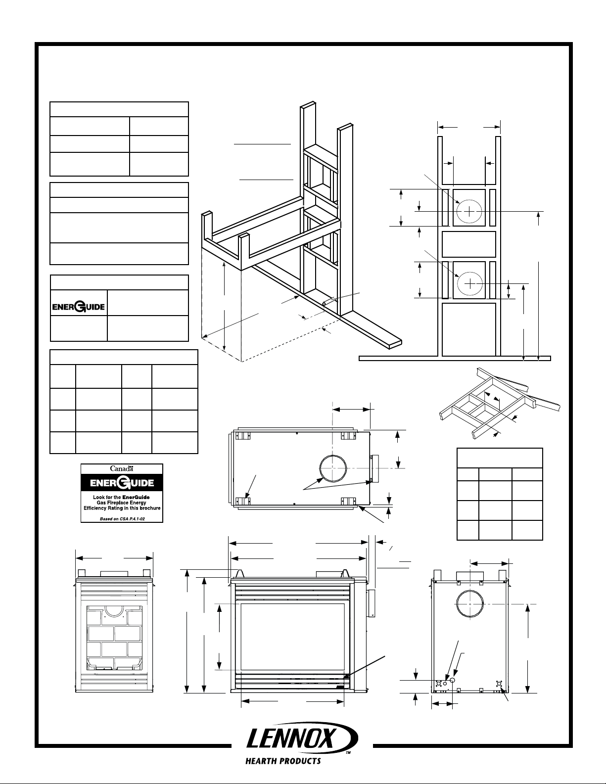
22
(559)
35-1/8
(892)
32-5/8
(827)
19
(483)
29 1/2
(749)
39-3/4 (984)
3 (76)
38-3/8 (899)
11 (279)
6-1/4
(159)
25-1/2
(646)
3-1/8 (79)
Louvered Control
Compartment Door
Gas
Inlet
Provide additional
space for Side
Vent Seal Cap if
installing against a
solid wall.
Front View
Left Side View
Right Side View
Control Switch Wires
Knock-Out
Junction Box
Knock-Out
10-7/8 (264)
11 (279)
(16)
5/8
Framing Spacers
(top and both sides)
Stepped to Accept Drywall
Vent Seal Cap
Top View
5-5/8
(143)
***38-3/4
(984)
35-1/4
(895)
**20-3/4
(527)
10-1/2
(267)
12-1/8
(308)
5-1/8
(130)
12-1/8
(308)
25-1/2
(648)
5-1/8
(130)
C
D
Millivolt Models Electronic Models
MPD35PF-NM MPD35PF-NE
MPD35PF-PM
SPECIFICATIONS
Natural Gas BTU Input 30,000
Propane Gas BTU Input 28,000
Co-axial DV Vent Size
4-1/2" Inner
7-1/2" Outer
NOTES
• Annual Fuel Utilization Efficiency
Due to Lennox' ongoing commitment to quality,
all specifications, ratings and dimensions are
subject to change without notice.
Appliance has a factory-installed vent seal cap in
each flue outlet. (see Installation Manual)
MPD35PF
Appliance Specifications
Fireplace Framing Specifications
***This dimension does
not include the addition
of drywall to the inside
of framing or clearance
for the Side Vent Seal Cap.
Adjust accordingly for your
installation.
See also, Side Vent Seal Cap
note below.
• Inches (millimeters)
Notes:
•
Minimum Framing Stud Size is 2 x 4
• See
side views of fireplace below
gas line inlet location options.
Vent Center - Top Vent
with one 90 degree
elbow
Vent Center - Side Vent
with no elbows
for
**This dimension
based on 5/8" drywall.
For 1/2" drywall use
21" (533 mm). The
finished dimension
should be 22" (558
mm)
Secure Vent
42-5/8 (1083)
Secure Flex
44-3/8 (1127)
EFFICIENCIES
61 % Natural Gas
62 % Propane Gas
• AFUE
65 % Natural Gas
67 % Propane Gas
PRODUCT REFERENCE INFORMATION
Cat.
No.
H6945 MPD35PF-NM 220 lbs 46W x 26D x
H6946 MPD35PF-PM 220 lbs 46W x 26D x
H6947 MPD35PF-NE 220 lbs 46W x 26D x
P/N 506035-04 REV. A 07/2008
Model Ship
Weight
43H (30 cu.ft.)
43H (30 cu.ft.)
43H (30 cu.ft.)
Ship.
Volumn
Center of gas line
is 3-1/8 inches
(79 mm) up from
floor.
See Ceiling Framing
on Page 2
Framing Dimensions for Roof
Inches (millimeters)
Pitch C D
0/12 10-1/2 in.
(267 mm)
6/12 10-1/2 in.
(267 mm)
12/12 10-1/2 in.
(267 mm)
10-1/2 in.
(267 mm)
12 in.
(305 mm)
17-3/4 in.
(451 mm)
Page 1 of 2
Page 2
1
(25)
2
(51)
3
(76)
1 (25)
2 (51)
3 (76)
4
(102)
4 (102)
5
(127)
5 (127)
6 (152)
7 (178)
8 (203)
9 (229)
10 (250)
3 (76)
2
(51)
4
(102)
6
(152)
8
(203)
10
(254)
12
(305)
5 (127)
9 (289)
13 (330)
11 (279)
7 (178)
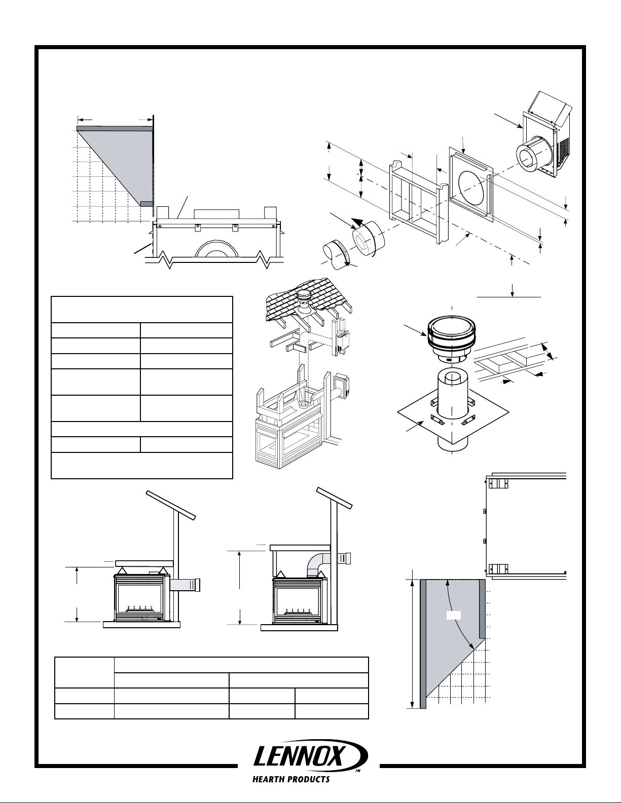
MPD35PF
10-1/2”
(267mm)
7"
(178)
5-1/8”
(130 mm)
12-1/8”
(308 mm)
3"
(76 mm)
1"
(25.4 mm)
Appliance Clearances
Millivolt Models Electronic Models
MPD35PF-NM MPD35PF-NE
MPD35PF-PM
Mantel Depth
Minimum Mantel Clearances
inches (millimeters)
Top of
Appliance
Front or Rear Face
of Appliance
Specifications and clearances are subject to change without notice. Refer to Installation Manual
before installation of these appliances for updated dimensions and instructions.
Minimum Appliance and Vent
Clearances - Inches (millimeters)
Sides 1/2 (13)
Top Spacers 0 (0)
Floor 0 (0)
Bottom of Appliance
To Ceiling
72 (1829)
Vent 3 (76) Top *
1 (25.4) Sides & Bottom
SERVICE CLEARANCES Feet (meters)
Front & Back Faces 3 ft. (0.9 m)
*Note: 3 in. (75 mm) above any horizontal /
inclined vent component.
Minimum Shelf Height Clearances
DIRECT VENT PENINSULA
MERIT® PLUS SERIES
Typical
Installation
Firestop / spacer (SV4.5HF) shown on the exterior side
of the wall. It may also be installed on the interior side.
Adapter SV4.5RCH
Hearth Extension - A hearth
extension is not required
with this appliance.
Square Horizontal Termination (SV4.5HT)
Note: Center line of Vent Piping is NOT
the Same as the Center line of the
Framed Opening.
6 to 48 inch Vent Section,
Telescopic vent section,
Elbow or Appliance Collar
Vertical Termination Cap
SV4.5CGV-1 (rated for
high winds and freezing
conditions)
See Roof Framing on Page 1
* Ceiling Firestop /
Spacer (SV4.5VF)
Combustible Materials
Allowed In Shaded Area
“Safe Zone”
Inches (millimeters)
At 5" minimum side
wall clearance, the wall
(shown in dark gray) can
be any length.
See Page 1 for Min.
Distance to Base of Appliance.
Base of Appliance
(See Roof Framing on Page 1)
Ceiling Framing
10 1/2 in.
(267 mm)
Top View of
Fireplace
10 1/2 in.
(267 mm)
Shelf Height
(see table)
Shelf Above Fireplace With Side Venting
Model No.
MPD35PF 35-1/4 (895) 49-3/8 (1254) 51-1/8 (1299)
Printed in U.S.A. © 2005 by LENNOX HEARTH PRODUCTS
P/N 506035-04 REV. A 07/2008
Side Vent - Straight Out Back Top Vent - with One 90 Degree Elbow
Secure Vent & Secure Flex Secure Vent Secure Flex
Shelf Height
(see table)
Shelf Above Fireplace With Top Venting
Shelf Height - Inches (millimeter)
o
45
Minimum Distance
to Unprotected
Side Wall
Minimum Side Clearances
Page 2 of 2
 Loading...