

Lennox MPA012S4S-*L, MWMB009S4-*L, MWMA009S4-*L, MPB009S4S-*L, MWMA012S4-*L Installation Instructions Manual
...Page 1
INSTALLATION
©
2017 Lennox Industries Inc.
Dallas, Texas, USA
Table of Contents
General ...........................................................................1
Included Parts.................................................................2
Model Number Identication ...........................................3
Indoor / Outdoor Unit Match-Ups....................................4
Typical System Components ..........................................5
System Dimensions ........................................................6
Outdoor Units ..............................................................6
Indoor Units .................................................................7
System Clearances ........................................................8
Outdoor Unit ................................................................8
Indoor Unit ...................................................................8
Torque Requirements for Caps and Fasteners...............9
Indoor Unit Installation ....................................................9
Unit Placement Considerations ...................................9
Determining Wall Mounting Plate Location ..................9
Installation of Wall Mounting Plate...............................9
Installation of Wall Sleeve..........................................10
Installation of Indoor Unit on Wall Mounting Plate .....10
Indoor Unit Condensate Piping Connections .............12
Outdoor Unit Installation ...............................................12
Placement Considerations .........................................12
Direct Sunlight, Rain, Snow and Ice Protection .........13
Prevailing Winds ........................................................14
Buried Refrigerant Pipe Protection ............................14
Outdoor Unit Condensate Piping ...............................14
Securing the Outdoor Unit .........................................15
Refrigerant Piping Connections ....................................15
Leak Test and Evacuation ............................................18
Leak Test ...................................................................18
Triple Evacuation Procedure......................................18
Wiring Connections ......................................................18
Outdoor Unit .............................................................18
Indoor Unit .................................................................18
Unit Start-Up .................................................................26
Adding Refrigerant for Longer Line Set ........................26
Troubleshooting ............................................................26
Test Run .......................................................................26
Pre-Checks ................................................................26
Procedure ..................................................................26
Double-Check Pipe Connections ...............................27
If Ambient Temperature is below 63°F (17°C) ...........27
Dry Mode Operation (Dehumidication) .......................27
Procedure ..................................................................27
Sequence of Operation ..............................................27
INSTRUCTIONS
MLA/MPA/MPB and
MWMA/MWMB Series
SINGLE-ZONE MINI-SPLIT SYSTEMS
(115V and 208/230V) --
Wall-Mounted Indoor Unit
507545-06
4/2017
Supersedes 10/2016
THIS MANUAL MUST BE LEFT WITH THE OWNER
FOR FUTURE REFERENCE
WARNING
Improper installation, adjustment, alteration, ser vice or
maintenance can cause property damage, personal
injury or loss of life.
Installation and service must be performed by a li censed
professional HVAC installer (or equivalent) or a service
agency.
WARNING
The clean Air Act of 1990 bans the intentional venting of
refrigerant (CFCs, HCFCs, and HFCs) as of July, 1992.
Approved methods of recovery, recycling or reclaiming
must be followed. Fines and/or incarceration may be
levied for non-compliance.
WARNING
This product contains a chemical known to the State
of California to cause cancer, birth defects, or other
reproductive harm.
CAUTION
As with any mechanical equipment, contact with sharp
sheet metal edges can result in personal injury. Take
care while handling this equipment and wear gloves and
protective clothing.
General
These instructions are intended as a general guide and
do not supersede local or national codes in any way.
Authorities having jurisdiction should be consulted before
installation.
The MWMA and MWMB wall-mounted indoor units are
matched with an outdoor heat pump unit to create a minisplit system that uses HFC-410A refrigerant.
Page 2
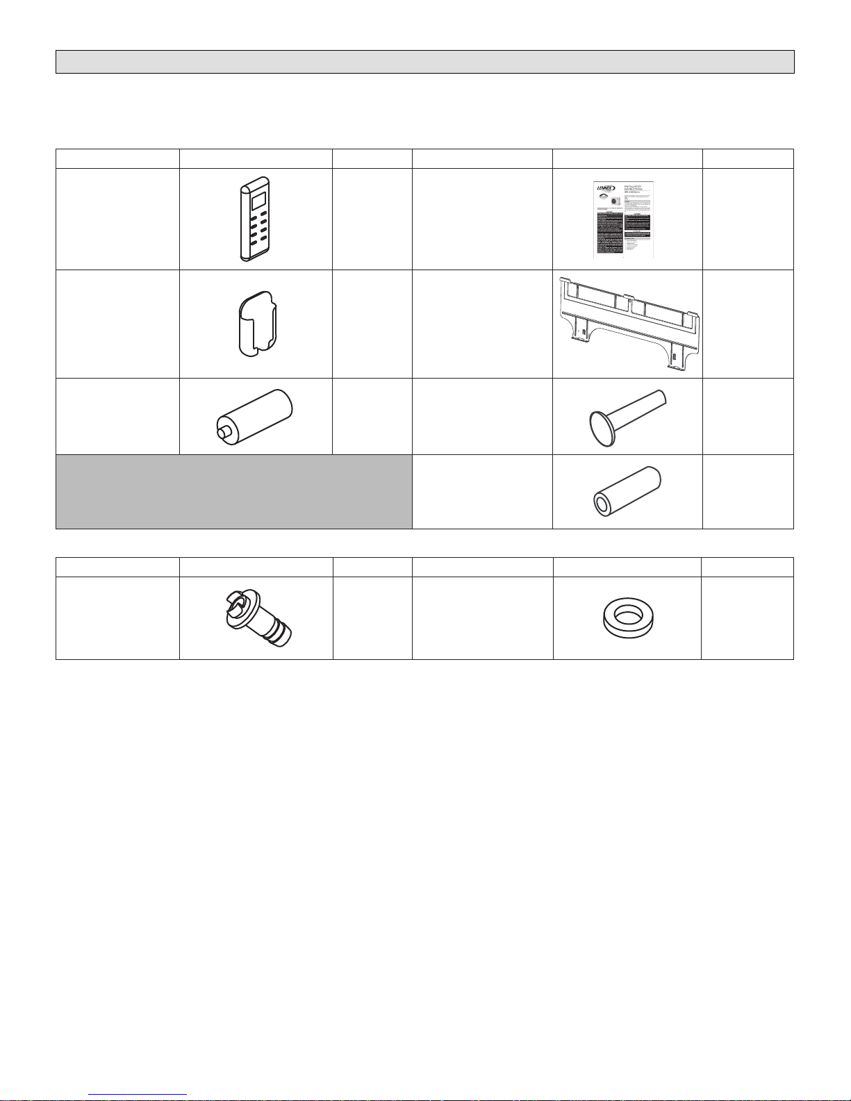
Included Parts
Package 1 of 1 contains the following:
1 - Assembled Indoor Unit
The assembled indoor unit will include the following items:
Parts Figure Quantity Parts Figure Quantity
M0STAT60Q-1
Wireless controller
Wireless control
holder with 2 mounting
screws
Batteries (AAA) 2
1
1 Mounting plate 1
Installation and owner’s
manual
Mounting plate securing
screws
Plastic screw anchors 5
1 - Assembled Outdoor Unit and the following items:
Parts Figure Quantity Parts Figure Quantity
1 ea.
5
Drain connector 1 Seal ring 1
2
Page 3
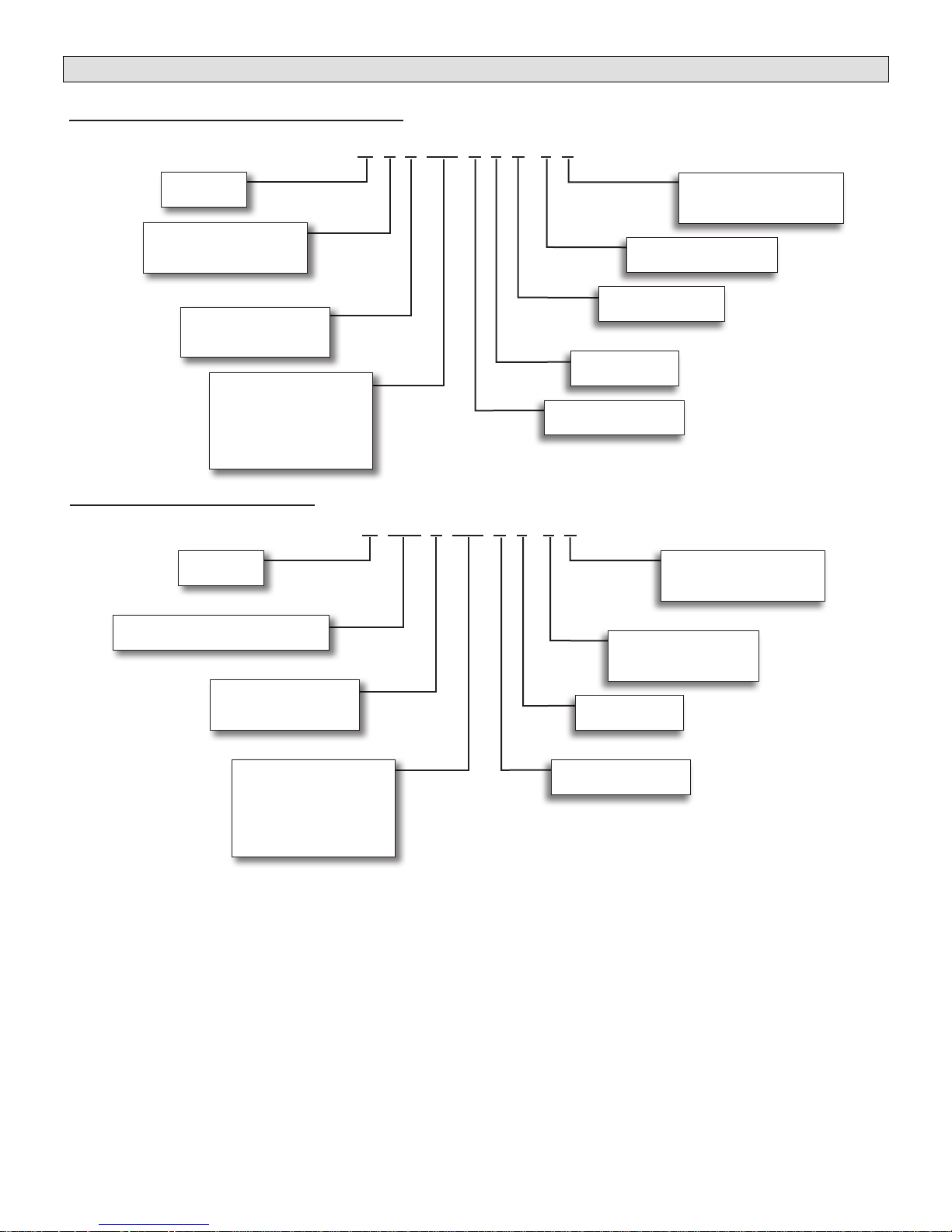
Model Number Identication
OUTDOOR SINGLE ZONE HEAT PUMP UNITS
M P A 009 S 4 S - 1 P
Series Type
M = Mini-Split
Unit Type
L = Low Ambient Heat Pump
P = Heat Pump
Major Design Sequence
A = 1st Generation
B = 2nd Generation
Nominal Cooling Capacity
009 = 0.75 tons
012 = 1 tons
018 = 1.5 tons
024 = 2 tons
030 = 2.5 tons
WALL-MOUNTED INDOOR UNITS
Series Type
M = Mini-Split
Unit Type
WM = Wall-Mounted Non-Ducted Unit
Major Design Sequence
A = 1st Generation
B = 2nd Generation
Voltage
L = 115V-1 phase-60hz
P = 208/230V-1 phase-60hz
Minor Design Sequence
1 = 1st Revision
Refrigerant Circuits
S = Single Circuit
Refrigerant Type
4 = HFC-410A
Cooling Efciency
S = Standard Efciency
M WM A 012 S 4 - 1 P
Voltage
L = 115V-1 phase-60hz
P = 208/230V-1 phase-60hz
Minor Design Sequence
1 = 1st Revision
2 = 2nd Revision
Refrigerant Type
4 = HFC-410A
Nominal Cooling Capacity
009 = .75 tons
018 = 1.5 tons
030 = 2.5 tons
Cooling Efciency
S = Standard Efciency
012 = 1 tons
024 = 2 tons
3
Page 4
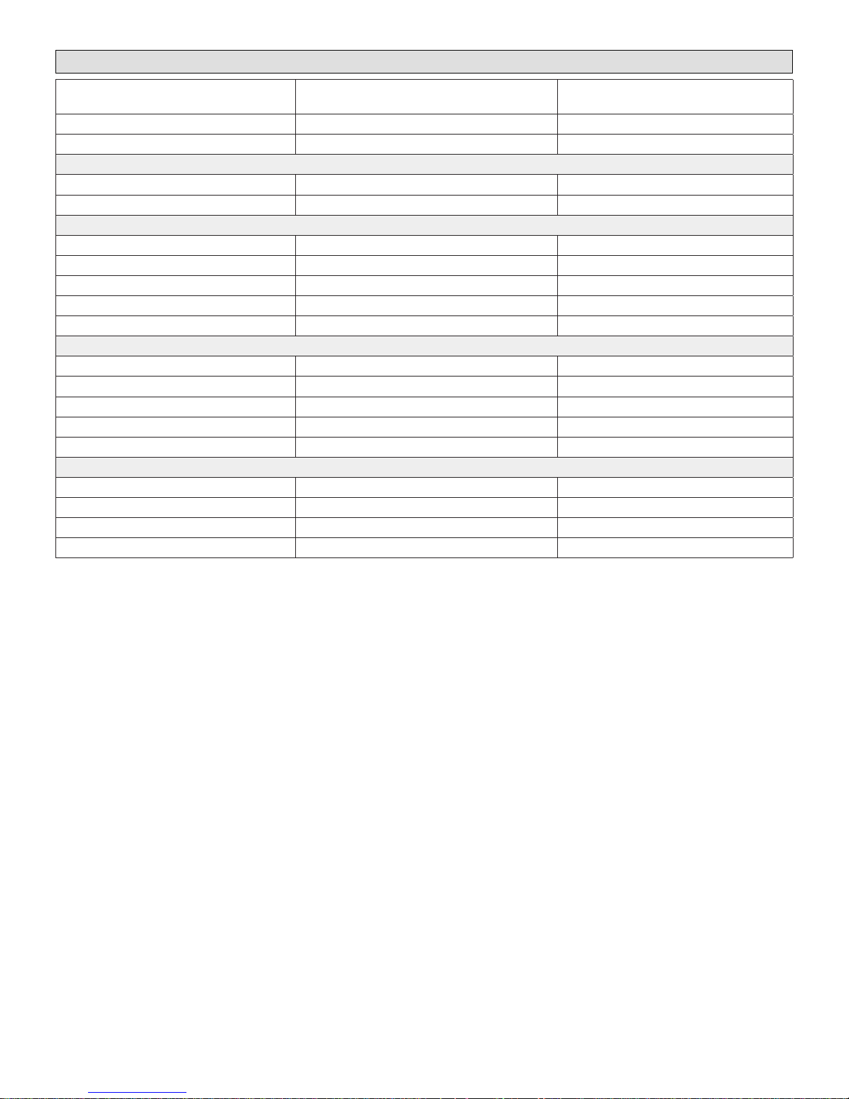
Indoor / Outdoor Unit Match-Ups
Outdoor Unit Indoor Unit Voltage
MPA009S4S-*L MWMA009S4-*L
MPA012S4S-*L MWMA012S4-*L
MPB009S4S-*L MWMB009S4-*L
MPB012S4S-*L MWMB012S4-*L
MPA009S4S-*P MWMA009S4-*P
MPA012S4S-*P MWMA012S4-*P
MPA018S4S-*P MWMA018S4-*P
MPA024S4S-*P MWMA024S4-*P
MPA030S4S-*P MWMA030S4-*P
MPB009S4S-*P MWMA009S4-*P
MPB012S4S-*P MWMA012S4-*P
MPB018S4S-*P MWMA018S4-*P
MPB024S4S-*P MWMA024S4-*P
MPB030S4S-*P MWMB030S4-*P
MLA009S4S-*P MWMA009S4-2P
MLA012S4S-*P MWMA012S4-2P
MLA018S4S-*P MWMA018S4-2P
MLA024S4S-*P MWMA024S4-2P
115V
115V
115V
115V
208/230V
208/230V
208/230V
208/230V
208/230V
208/230V
208/230V
208/230V
208/230V
208/230V
208/230V
208/230V
208/230V
208/230V
4
Page 5
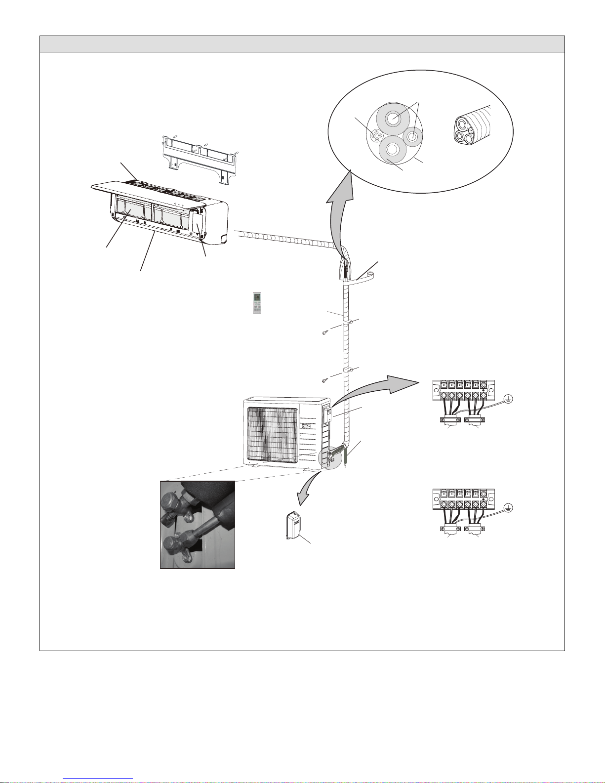
Typical System Components
IMPORTANT - Condensate drain line must always
be located at the bottom of the
bundle.)
Mounting Plate
Wiring
Line set
(wrapped in foam insulation)
Filter
Return Air
Supply Air
Indoor Unit
Indoor unit wiring connections
(under access plate)
Utility
Wireless Remote
Control
Outdoor Unit
009-030 shown
Bundle
Access cover for power
and control wiring
connections
Condensate drain line
(field-provided)
TAPE
Condensate drain line
(wrapped in foam insulation)
Refrigerant Line Set, Condensate Line
And Indoor / Outdoor Cable
(field-provided)
UV-rated tape (field-provided)
IMPORTANT - The refrigerant
metering device for this system is
located in the outdoor unit. This
makes it necessary to insulate the
refrigerant lines individually to
prevent sweating.
208/230V Outdoor Unit
Terminal Block
1 2 3 L1 L2
To Indoor
Unit
To Power
Supply
Liquid and vapor shut off valves
Figure 1. Typical System Shown
5
Access cover
for valves
115V Outdoor Unit
Terminal Block
1 2 3 L N
To Indoor
Unit
To Power
Supply
Page 6
System Dimensions
A
E
D
B
C
TYPICAL APPEARANCE OF UNITS
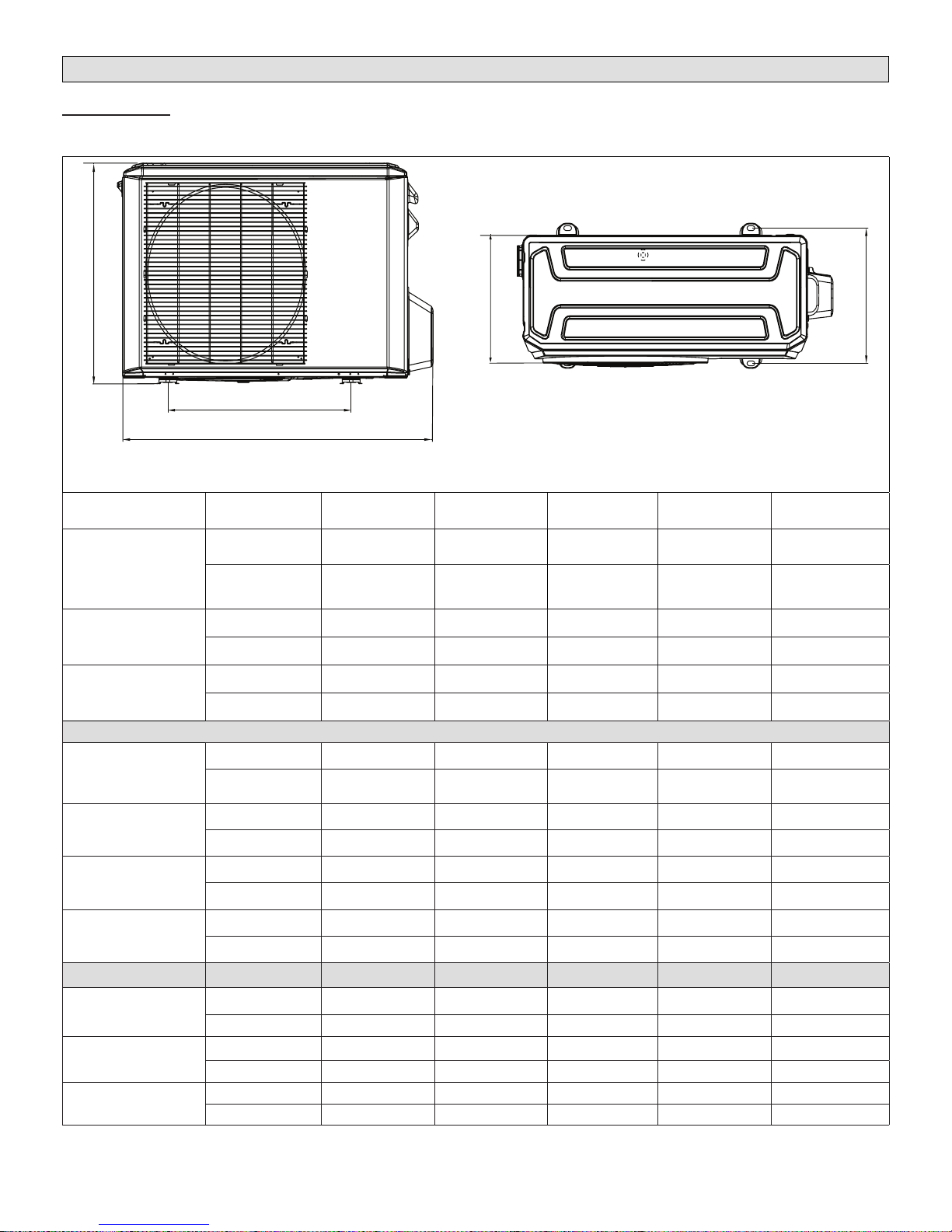
Outdoor Units
Table 1. Outdoor Unit Dimensions - Inches (mm)
Model
MPA009S4S-*L
MPA009S4S-*P
MPA012S4S-*L
MPA012S4S-*P
MPA018S4S-*P
MPA024S4S-*P
MPA030S4S-*P
MPB009S4S-*L
MPB012S4S-*L
MPB012S4S-*P
MPB009S4S-*P
MPB018S4S-*P
MPB024S4S-*P
MPB030S4S-*P
Unit of
Measurement
inches 33-1/4 21-5/8 22 11-3/8 12-3/4
mm 845 549 559 289 324
inches 36-1/8 22 27-1/2 12-3/4 13
mm 918 559 699 324 330
inches 40-5/8 25-1/4 31-7/8 15-1/8 16
mm 1032 641 810 384 406
inches 34-1/4 20-1/4 21-7/8 13-1/8 13-3/8
mm 870 514 556 333 340
inches 33-1/8 19-1/8 21-7/8 11-7/8 11-3/4
mm 842 486 556 302 298
inches 36 21-1/4 27-5/8 14-1/4 13-3/4
mm 914 540 702 362 349
inches 37-1/4 26-1/2 31-7/8 16-3/8 15-7/8
mm 1032 673 810 416 403
A B C D E
MLA009S4S-*P
MLA012S4S-*P
MLA018S4S-*P
MLA024S4S-*P
inches 34-1/4 20-1/4 21-3/4 12-1/4 13-3/8
mm 870 514 552 311 594
inches 36 21-1/4 27-5/8 13-3/4 16
mm 914 540 702 349 406
inches 40-3/4 26-1/2 31-7/8 15-1/8 16
mm 1035 673 810 384 406
6
Page 7
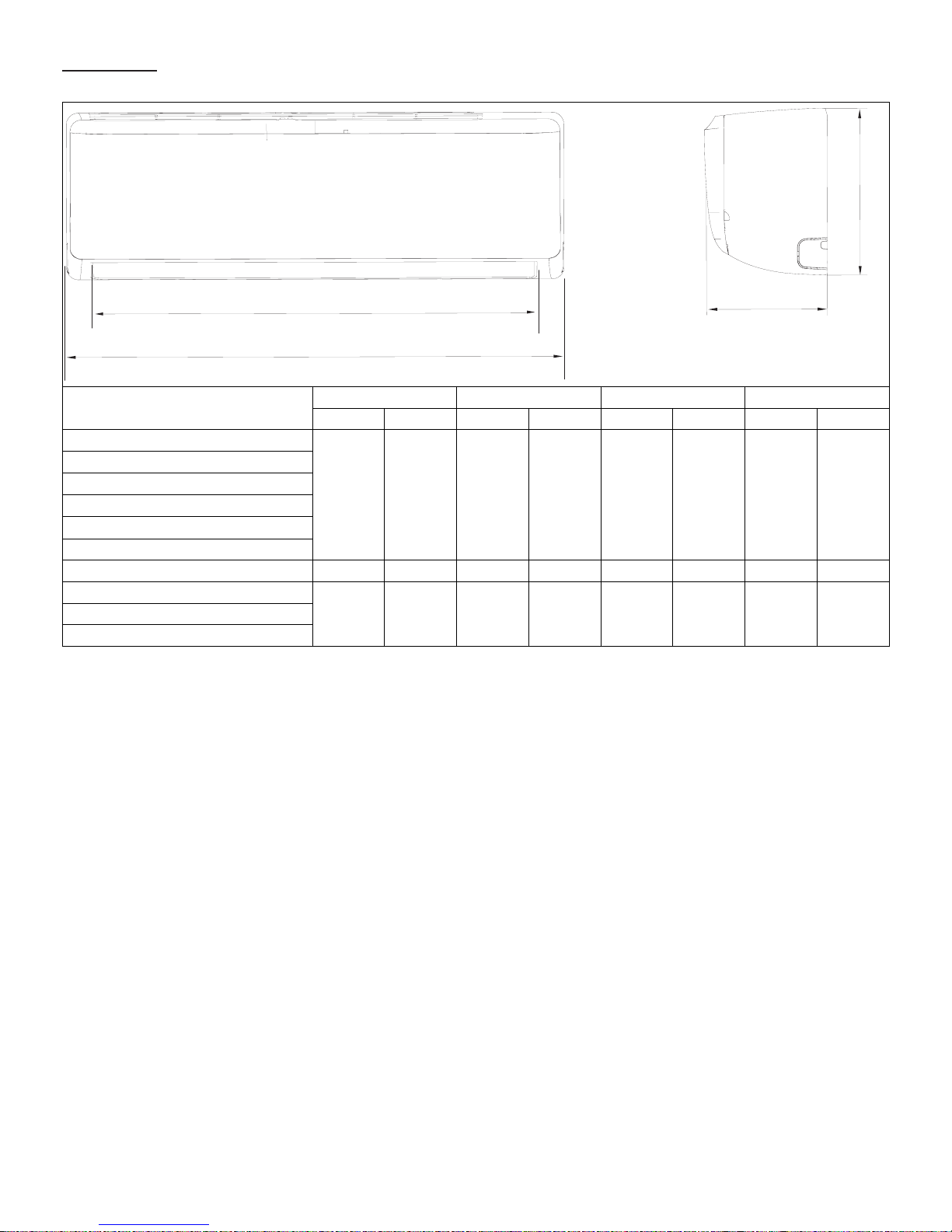
Indoor Units
B
A
Table 2. Indoor Unit Dimensions - Inches (mm)
C
D
Size
MWMA009S4S-*L
MWMB009S4S-*L
MWMA012S4S-*L
MWMB012S4S-*L
MWMA009S4S-*P
MWMA012S4S-*P
MWMA018S4S-*P 39 991 12-3/8 314 34-3/4 883 8-5/8 210
MWMA024S4S-*P
MWMB030S4S-*P
32-7/8 835 11 279 29-1/4 743 7-7/8 200
46-3/4 1187 13-1/2 343 42-1/2 1080 10-1/4 260MWMA030S4S-*P
A B C D
in. mm in. mm in. mm in. mm
7
Page 8
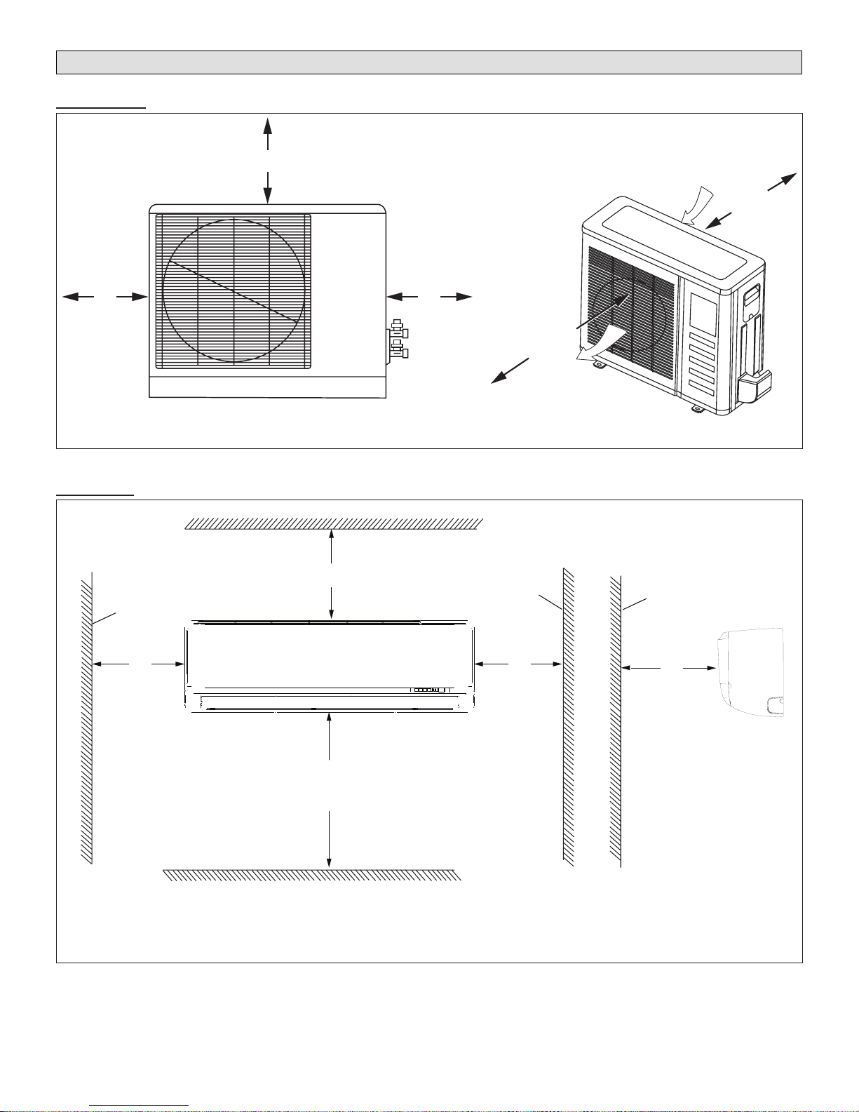
System Clearances
Outdoor Unit
12
(305)
Indoor Unit
Wall
24 (610)
24
(610)
1
Minimum rear clearance can be 6 inches (152 mm) when mounted on brackets
and with no obstructions on the other three sides.
Figure 2. Outdoor Unit Clearances - Inches (mm)
Ceiling
6” (152 mm)
Minimum Clearance
5”
(127 mm)
Minimum
Wall
5”
(127 mm)
Minimum
79
(2007)
Air Outlet
Air Inlet
1
12
(305)
Any Object
59”
(1499 mm)
Minimum
Vertical Clearance - Clearance to Floor - 72 inches (1829 mm) Minimum
96 inches (2438 mm) Recommended
Figure 3. Indoor Unit Clearances - Inches (mm)
Floor
FRONT VIEW
SIDE VIEW
8
Page 9
Torque Requirements for Caps and
Fasteners
When servicing or repairing HVAC components, ensure
the fasteners are appropriately tightened. “Table 1. Torque
Requirements” on page 9 provides torque values for
fasteners.
IMPORTANT
Only use Allen wrenches of sufcient hardness (50Rc -
Rockwell scale minimum). Fully insert the wrench into
the valve stem recess.
Service valve stems are factory-torqued from 9 ft.-lbs.
(12 N*m) for small valves, to 25 ft.-lbs. (34 N) for large
valves) to prevent refrigerant loss during shipping and
handling. Using an Allen wrench rated at less than 50Rc
risks rounding or breaking off the wrench, or stripping
the valve stem recess.
See the Lennox Service and Application Notes C-08-1
for further details and information.
Table 1. Torque Requirements
Parts
Service valve cap 8 ft.-lb. 11
Sheet metal screws 16 in.-lb. 2
Machine screws #10 27 in.-lb. 3
Compressor bolts 7 ft.-lb. 10
Gauge port seal cap 8 ft.-lb. 11
Recommended Torque
U.S. Newton-Meter- N
Indoor Unit Installation
CAUTION
In order to avoid injury, take proper precaution when
lifting heavy objects.
Unit Placement Considerations
AVOID
Do not install the unit in the following locations:
• Areas exposed to petrochemicals or petrochemical
products
• Areas exposed to salt or other corrosive materials or
caustic gases
• Areas exposed to extreme voltage variations (such as
factories
• Tightly enclosed areas that may impede service of the
unit
• Areas exposed to fossil fuels (such as oil or gas in
kitchens)
• Areas exposed to strong electromagnetic forces
• Areas exposed to acids or alkaline detergents
DO
• Place the unit so that it is not exposed to direct sunlight
• Ensure the structural ceiling can support the weight of
the unit
• Select a location where condensate line will have the
shortest run to a suitable drain per local codes
• Allow sufcient space around unit for proper operation
and maintenance
• Install unit a minimum of 3 feet (1m) away from any
antenna, power cord (line) radio, telephone, security
system, or intercom. Electrical interference and radio
frequencies from any of these sources may affect operation
• Be sure to instruct customers how to properly operate
the unit (especially maintenance of air lter, and operation procedure) by having them carry out operations
themselves while looking at the manual provided with
the controller
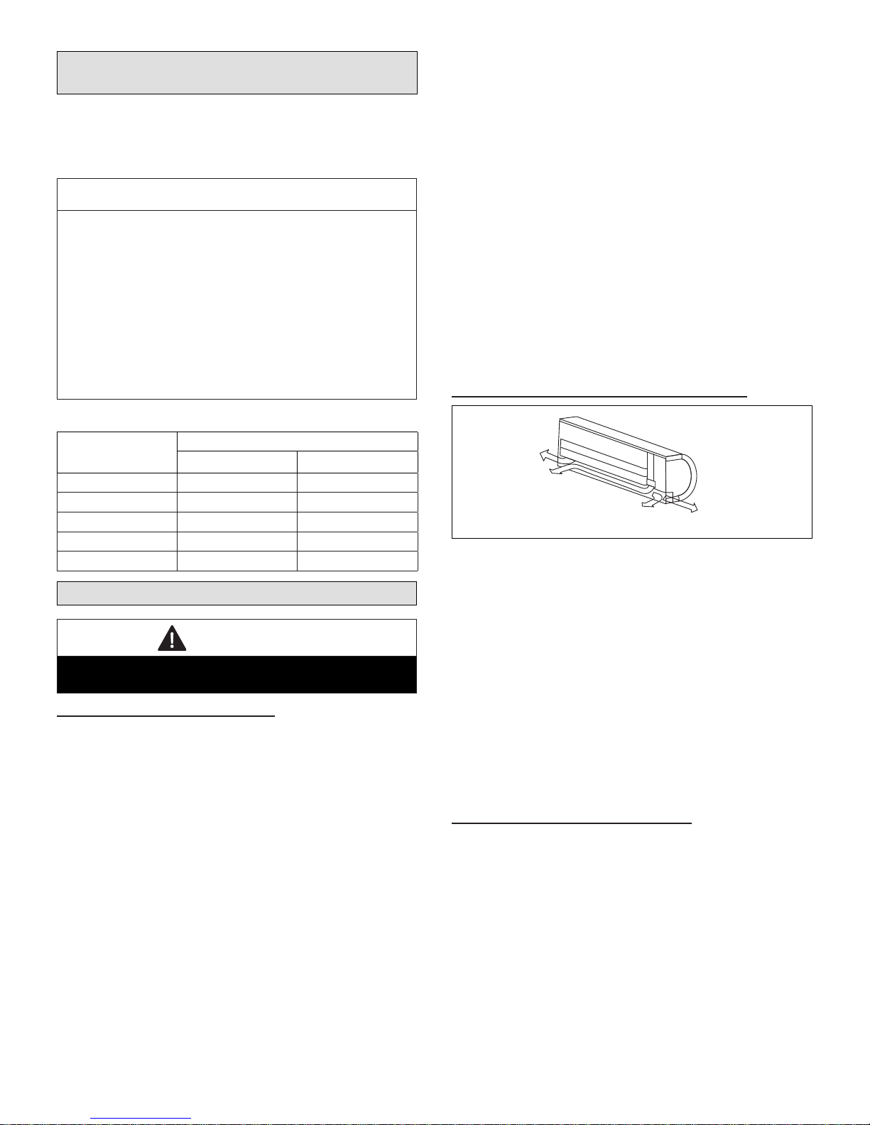
Determining Wall Mounting Plate Location
Left piping
Left back piping
Right back piping
Right piping
Figure 4. Determining Exit Locations
1. Remove the wall mounting plate from the back of the
indoor unit.
2. Determine the best exit location for utility bundle (line
set, condensate line and wiring). See the following
section concerning wall sleeve installation instructions.
3. Position the wall mounting plate on the wall so that,
when installed, the unit will be at least 6 inches (152
mm) from the ceiling and 5 inches (127 mm) from the
wall on either side. The wall mounting plate must be
level side-to-side.
4. Use the wall mounting plate as a template to determine
the exit point for utility bundle. Mark the wall to facilitate
drilling hole for utility bundle.
Installation of Wall Mounting Plate
Install the wall mounting plate (see “Figure 8. Wall
Mounting Plates - Inches (mm)” on page 11) so that it is
correctly positioned horizontally and vertically. The indoor
unit must be installed level on the wall to allow proper
condensate drainage.
1. Use a carpenter’s level or measuring tape to verify the
wall mounting plate is horizontally level.
2. Secure the wall mounting plate to the wall using the
provided screws and screw anchors.
NOTE: It is important to use all screws provided to secure
the wall mounting plate to the wall. Additional holes
may be drilled through the metal wall mounting
9
Page 10

plate to better secure wall plate. Field-provided
anchors/xings may be required depending on wall
construction. Use the appropriate type of anchors
for the application.
3. The wall mounting plate must be installed ush against
the wall so that the indoor unit will be ush after
installation. Any space between the wall and unit will
cause noise and vibration.
4. The wall mounting plate must be installed horizontally
level on the wall.
Installation of Wall Sleeve
The utility bundle may be routed out of the back of the unit
or out either side. If the bundle is to be routed out the back
through an external wall, use a eld-provided wall sleeve
to protect the utility bundle.
NOTE: If the utility bundle will be routed out the side of the
indoor unit and up the wall above a false ceiling,
continue to the next section.
1. Prior to making the hole and installing the wall sleeve
for the utility bundle, check to ensure that there are
no other utilities located in the wall behind the hole
location.
2. Cut a hole in the wall using a suitable hole saw. Hole
should be at a slight downward slant - 3/16” to 3/8”
toward the outdoor side.
3. Measure the thickness of the wall from the inside edge
to the outside edge and cut the eld-provided wall
sleeve at a slight angle 1/4” (6 mm) shorter than the
thickness of the wall.
Installation of Indoor Unit on Wall Mounting Plate
1. A length of eld-provided exible condensate piping
should be connected to the drain prior to securing the
unit to the wall mounting plate.
2. If the factory-provided refrigerant piping connections
and eld-provided exible condensate piping are long
enough to enable nal eld connections after unit is
installed on wall mounting plate, use eld-provided
tape to bundle them together.
3. The utility bundle may be routed out of the back of the
unit or out either side. If the bundle is to be routed
out the back through an external wall, feed the utility
bundle through the wall sleeve. If the utility bundle is
to be routed out of the side of the indoor unit and up
an inside wall, carefully form the utility bundle so that
it makes a gentle 90° turn.
4. Align the back of the indoor unit with the hooks at the
top of the wall mounting plate. Move the unit from side
to side to make sure that it settles securely.
5. The bottom of the unit can be lifted to facilitate
refrigerant piping and condensate drain connections,
if necessary.
HOOKS AT TOP
OF MOUNTING
BRACKET
TEMPORARY
SPACER
(To facilitate
connections)
INSIDE
OUTSIDE
Typical
installation
procedure
shown.
Figure 5. Boring Hole for Wall Sleeve
USE SUITABLE TOOL TO CUT PVC FOR WALL
SLEEVE AT SLIGHT ANGLE AS SHOWN.
Figure 6. PVC Wall Sleeve Installation
NOTE: When passing bundled services through an
exterior brick or concrete wall, protect the
copper pipes and wiring from the effects of these
construction materials by using a sleeve made
of suitable material. The integrity of copper pipe
and wiring can deteriorate when exposed to these
construction materials.
Figure 7. Secure Unit to Wall Mounting Plate
10
Page 11

MWMA009S4, MWMB009S4, MWMA012S4, MWMB012S4
5-1/2 (140)
1-3/4 (44)
Left rear side
refrigerant pipe inlet
2-1/2 (64) diameter
7/8 (22)
Left rear side
refrigerant pipe inlet
2-1/2 (64) diameter
12-3/8 (314)
10-1/4 (260)
32-7/8 (835)
MWMA018SA
39 (991)
4-3/8
(111)
1-3/8
(35)
5-1/4 (133)
Indoor unit
outline
11 (279)
1-3/4 (44)
Right rear side
refrigerant pipe inlet
2-1/2 (64) diameter
Indoor unit
outline
1-3/4 (45)
Right rear side
refrigerant pipe inlet
2-1/2 (64) diameter
Left rear side
refrigerant pipe inlet
2-1/2 (64) diameter
MWMA024S4, MWMA030S4, MWMB030S4
10-1/8
(257)
46-3/4 (1187)
10-7/8
(276)
7/8 (22)
Figure 8. Wall Mounting Plates - Inches (mm)
Indoor unit
outline
13-1/2 (343)
1-3/4 (44)
Right rear side
refrigerant pipe inlet
2-1/2 (64) diameter
11
Page 12

Indoor Unit Condensate Piping Connections
e no
IMPORTANT
Make sure that drain piping is properly routed and
insulated to prevent both leaks and condensation.
1. Use a eld-provided hose clamp to secure the drain
line stub on the side of the cabinet to a eld-supplied
1-inch (25 mm) drain line.
NOTE: Take care not to over-tighten the hose clamps this
may damage the drain line stub.
NOTE: Connection between stub and drain line must be
watertight. Apply non hardening plumbing joint
compound if needed to ensure a watertight seal.
2. Conrm proper slope (not less than 1/4 inch per foot
(18 mm per m)) and routing of condensate lines to
ensure moisture is drained away from the indoor unit.
3. Drain should be as short as possible and should
not have any droops or kinks that would restrict
condensate ow and shall be approved resistant pipe.
There must be a 2-inch (51 mm) space between the
end of the condensate drain and the nal termination
point (ground, open drain, etc.) to ensure that the line
will drain freely.
4. After the system installation is complete, the
condensate drain line must be checked for leaks and
proper drainage. If a eld-provided condensate pump
has been installed, it must be checked to ensure proper
operation. This check is part of the start-up process
which must be done by the installing contractor.
IMPORTANT
Drain should have a slope of at least ¼ inch per foot and
should be approved corrosion-resistant pipe. You must
conrm operation of every drain and pump in the system
as part of the commissioning procedure.
CORRECT
Make sure there ar
kinks or dent in drain
hose to ensure proper
drainage.
Figure 9. Condensate Line
Outdoor Unit Installation
Placement Considerations
Consider the following when positioning the unit:
• In coastal areas or other places with salty atmosphere
of sulfate gas, corrosion may shorten the life of the
unit. In coastal areas, the coil should be cleaned with
potable water several times per year to avoid corrosive
buildup (salt)
• Some localities are adopting sound ordinances based
on the unit’s sound level registered from the adjacent
property, not from the property where the unit is installed. Install the unit as far as possible from the property line
• When possible, do not install the unit directly outside
a window. Glass has a very high level of sound transmission
• Install unit level
Building Structure
Ground
Level
Figure 10. Install Unit Level
• Choose a place solid enough to bear the weight and
vibration of the unit, where the operation noise will not
be amplied
• Choose a location where the hot air discharged from
the unit or the operation noise will not be a nuisance
to neighbors
• Avoid installing the outdoor unit near a bedroom or
other places where noise may cause a problem
• There must be sufcient space to carry the unit into
and out of the site
• There must be unobstructed air ow around the air inlet and the air outlet
• The unit must not be installed in areas where a ammable gas leak may occur
• Install the outdoor unit a minimum of 3 feet (1m) away
from any antenna, power cord (line), radio, telephone,
security system, or intercom. Electrical interference
and radio frequencies from any of these sources may
affect operation
• Since water drains from the outdoor unit during various stages of operation, do not place anything which
may be damaged by moisture under the unit
CAUTION
In order to avoid injury, take proper precaution when
lifting heavy objects.
12
Page 13

Direct Sunlight, Rain, Snow and Ice Protection
Air Inlet
Air Outlet
• If the outdoor unit is subjected to prolong exposure to
direct sunlight with temperatures over 100°F (38°C) a
canopy is recommended as illustrated in “Figure 11.
Outdoor Unit on Pedestal and Protective Canopy” or
“Figure 16. Dog House-Style Shelter” on page 14
IMPORTANT
The construction of a canopy or shade is necessary
because of an ambient limit control set to 122°F (50°C)
to protect the electronics. If the outdoor unit is placed in
direct sunlight it is possible that the limit may activate
and shut down the unit.
• Place unit away from overhanging roof lines which
would allow water or ice to drop on, or in front of, coil
or into unit. Construct a canopy as illustrated in “Figure
11. Outdoor Unit on Pedestal and Protective Canopy”
• The unit base should be elevated above the depth of
average snows as illustrated in “Figure 12. Outdoor
Unit on Brackets above Snow Line”
• In heavy snow areas, do not place the unit where drifting will occur as illustrated in “Figure 13. Outdoor Unit
Air Flow Obstructed by Snow”
• Carefully consider how to manage defrost water disposal to prevent ice from blocking walkways or creating a safety hazard near the outdoor unit as illustrated
in “Figure 14. Avoid Defrost Water Ice Hazard”
Protective canopy
Protective canopy
Figure 12. Outdoor Unit on Brackets above Snow
Line
12 in
79 in
2007 mm
Air Outlet
305 mm
Air Inlet
24 in
610 mm
12 in
305 mm
Side View
Air Inlet
Front View
Pedestal
(stand)
Pedestal
(stand)
Air Outlet
Figure 11. Outdoor Unit on Pedestal and Protective
Canopy
Figure 13. Outdoor Unit Air Flow Obstructed by
Snow
Figure 14. Avoid Defrost Water Ice Hazard
13
Page 14

Prevailing Winds
12 in
305 mm
24 in
610 mm
24 in
610 mm
12 in
305 mm
NOTE - Minimum clearances shown.
Drain
Connector
Chassis
Condensate Drain
(location varies per model)
Normally wind bafes are not required for a outdoor unit.
However, in order to maximize reliability and performance,
the following best practices should be followed.
If unit coil cannot be installed away from prevailing winter
winds, some method of protecting the coil is recommended.
However, minimum clearances as reference in “Figure 2.
Outdoor Unit Clearances - Inches (mm)” on page 8
must be observed at all times.
Common application examples are:
• When prevailing winds are from the air inlet side, then
position the wind barrier a minimum of 12 inches (305
mm) from the unit as illustrated in “Figure 15. Wind
Barrier”
• When prevailing wind is into the discharge side, then
position the wind barrier a minimum 79 inches (2007
mm) from the front of the unit as illustrated in Figure
14. Wind Barrier”
• Outdoor unit can be installed in a dog house style
shelter as illustrated in “Figure 16. Dog House-Style
Shelter”
• Outdoor unit can be installed in a alcove or under
a roof overhang as illustrated in “Figure 17. Unit Installed in Alcove”
Prevailing Winter Winds from Air Inlet Side
24 in
610 mm
12 in
305 mm
NOTE - Minimum clearances shown.
12 in
305 mm
610 mm
24 in
Figure 17. Unit Installed in Alcove
Buried Refrigerant Pipe Protection
• All refrigerant lines must be insulated regardless of if
it is buried
• In addition to insulating each line of piping, buried lines
must rest inside a sealed, watertight conduit
• The conduit must be designed so it cannot collect and
retain water
Wind Barrier
Inlet Air
Discharge Air
Wind Barrier
Prevailing Winter Winds From Air Discharge Side
12” (305mm)
Min. Distance
79” (2007mm)
Min. Distance
Figure 15. Wind Barrier
Outdoor Unit Condensate Piping
Condensate formed during the heating and defrost
processes must be drained from heat pump units. Drain
holes are provided in the base of the units to ensure proper
drainage. Heat pumps must be raised when installed on a
concrete pad or the ground to allow drainage to occur. If
the heat pump unit is installed on wall mounting bracket,
insert the provided drain connector into one of the 1
inch (25 mm) drain holes and attached a eld-provided
insulated drain hose to the connector. Use eld-provided
rubber plugs to cover any unused drain holes as illustrated
in “Figure 18. Condensate Drain”.
Figure 16. Dog House-Style Shelter
Figure 18. Condensate Drain
14
Page 15

Securing the Outdoor Unit
Slab or Roof Mounting
Install the unit a minimum of 4 inches (102 mm) above the
roof or ground surface to avoid ice build-up around the
unit. Place the unit above a load bearing wall or area of
the roof that can adequately support the unit. Consult local
codes for rooftop applications.
CAUTION
Roof Damage!
This system contains both refrigerant and oil. Some
rubber roong material may absorb oil. This will cause
the rubber to swell when it comes into contact with oil.
The rubber will then bubble and could cause leaks.
Protect the roof surface to avoid exposure to refrigerant
and oil during service and installation. Failure to follow
this notice could result in damage to roof surface.
6 in
152 mm
Air Inlet
Air Outlet
Figure 21. Securing Outdoor Unit to Brackets
Securing Outdoor Unit to Slab, Frame, or Rails
If the outdoor unit is installed on a eld-provided slab or
frame, use lag bolts or equivalent to secure the outdoor
unit to the slab or frame.
Four Field-provided Anchor Bolts
Figure 19. Securing Outdoor Unit to Slab
Four Field-Provided
Anchor Bolts
Refrigerant Piping Connections
Field piping consists of two copper lines connecting the
outdoor unit to the indoor unit. “Table 2. Refrigerant Piping
and Indoor Unit Connection Sizes” lists the connection
sizes. The connections are made using the provided brass
are nuts at the end of the refrigerant piping connections.
Both lines must be individually insulated.
1. The seal on the unit refrigerant piping connections
should remain in place until the last possible moment.
This will prevent dust or water from getting into the
refrigerant piping before it is connected.
2. CAREFULLY adjust refrigerant piping connections to
suit the application.
3. Slowly loosen one of the are nuts to release the
factory nitrogen charge from the indoor units only.
4. Remove the are nuts from the connections on the
unit and discard the seal from each of the piping
connections.
5. Slide the are nuts onto the ends of the eld-provided
refrigerant piping before using a suitable aring tool to
are the end of the copper pipe.
6. Apply recommended HFC-410A refrigerant lubricant
to the outside of the ared refrigerant lines.
Figure 20. Securing Outdoor Unit to Rails
Securing Outdoor Unit to Hanging Brackets
If the outdoor unit is installed on eld-provided wall
mounting brackets, use lag bolts or equivalent to secure
the outdoor unit to the bracket. Minimum rear clearance
can be reduced to 6 inches (152 mm) when mounted
on brackets and with no obstructions on the other three
sides. Allow for condensate disposal when placing units
above one another.
IMPORTANT
The compressor in this unit contains PVE
oil (Polyvinylether). PVE oil is formulated for
hydrouorocarbon (HFC) refrigerants, such as HFC-
410A, which this system contains. While it may have
some miscibility properties with mineral-based oil and
POE oil (Polyolester), it is not recommended to mix PVE
oil with any other type of refrigerant oil.
15
Page 16

7. Align the threaded connections with the
ared refrigerant lines. Tighten the are nuts
lightly at rst to obtain a smooth match as
illustrated in “Figure 22. Making Connections
(Male to Female Connection)”.
8. Once snug, continue another half-turn on each nut
which should create a leak-free joint. A torque wrench
may be used to tighten are nuts using “Table 3. Flare
Nut Torque Recommendations”. Do not over-tighten
a ared joint. Flared connections should always
be accessible and must be insulated to prevent
condensation.
9. After refrigerant piping has been installed and checked
for leaks, apply insulation over all ared connections.
Table 2. Refrigerant Piping and Indoor Unit
Connection Sizes
Size
(Btuh)
9000 1/4 3/8
12000 1/4 1/2
18000 1/4 1/2
24000 3/8
30000 3/8 5/8
Liquid Line
in.
Suction Line
in.
5/8
Table 3. Flare Nut Torque Recommendations
Outside
Diameter
Inches
1/4 15 ft.-lb. (20 N) 1/4 turn
3/8 26 ft.-lb. (35 N) 1/2 turn
1/2 41 ft.-lb. (56 N) 7/8 turn
5/8 48 ft.-lb. (65 N) 1 full turn
Recommended
Torque
No torque wrench available
Finger tighten and use an
appropriately sized wrench to
turn an additional:
A
CANT ON THE OUTSIDE OF
THE FLARE
MALE FLARE
CONNECTION
B
Figure 22. Making Connections
(Male to Female Connection)
IMPORTANT
Always use two wrenches when tightening are nuts to
avoid twisting refrigerant piping. DO NOT over-tighten
are nuts.
TORQUE WRENCH
TO INDOOR
UNIT
BACKUP
WRENCH
TO OUTDOOR UNIT
Figure 23. Tighten Flare Nut
16
Page 17

Table 4. Refrigerant Line Set Requirements
OUTDOOR UNIT
OUTDOOR UNIT
INDOOR UNIT
INDOOR UNIT
Maximum Line Set
Length
Maximum Line Set
Length
Maximum
Elevation -
Outdooor
Unit BELOW
Indoor Unit
Maximum
Elevation -
Outdooor
Unit ABOVE
Indoor Unit
Minimum Line Set
Length - 10 ft. (3m)
Minimum Line Set
Length - 10 ft. (3m)
Outside Unit BELOW Indoor Unit Outside Unit ABOVE Indoor Unit
Do not allow for excess length of line sets to be left rolled up as part of the
required distance, or in general. This will also cause additional performance issues.
IMPORTANT
Each system size has a line set length and vertical elevation parameters.
Line Set Diameters (in.)
System Size (KBtu)
Liquid Gas
009 1/4 3/8 40 (12) 40 (12) 82 (25)
012 1/4 1/2 40 (12) 40 (12) 82 (25)
018 1/4 1/2 66 (20) 66 (20) 98 (30)
024/030 3/8 5/8 82 (25) 82 (25) 164 (50)
Maximum Elevation
Outdoor Unit BELOW
Indoor Unit - Feet
(Meter)
Maximum Elevation
Outdoor Unit ABOVE
Indoor Unit - Feet
(Meter)
Maximum Line
Set Length - Feet
(Meters)
17
Page 18

Leak Test and Evacuation
Air and moisture remaining in the refrigerant system will
have undesirable effects as indicated below:
• Pressure in the system rises
• Operating current rises
• Cooling or heating efciency drops
• Moisture in the refrigerant circuit may freeze
• Water may lead to corrosion of parts in the refrigeration system
The line set between the indoor and outdoor units
must be leak tested and evacuated to remove any noncondensables and moisture from the system.
Leak Test
Use the following procedure to test for system leaks:
1. Connect the manifold gauge set and dry nitrogen gas
cylinder to the suction and gas service ports.
2. Open valve on nitrogen cylinder.
3. Pressurize the system per the pressure test
specications in “Table 5. Pressure Test Specications”.
4. Check that the system pressure remains stable. If
there is any movement check system for leaks.
5. After the system is found to be free of leaks:
• Close valve on nitrogen cylinder
• Relieve the nitrogen pressure by: loosening the
charge hose connector at the nitrogen cylinder
• When the system pressure is reduced to normal,
disconnect the hose from the cylinder
Table 5. Pressure Test Specications
Bar Psig kPa Duration
1 3 44 303 Minimum of 10 minutes
2 15 220 1517 Minimum of 10 minutes
3 32 470 3241 Minimum of 10 minutes
4 45 650 4482
5 32 470 3241
1 hour. Stress test to prove the
integrity of the complete installation.
24 hours. Lower system pressure
test, after conrmation No. 4 was
successfully completed.
IMPORTANT
Use only oxygen-free nitrogen (OFN).
Triple Evacuation Procedure
A Micron or Torr gauge must be used for this procedure.
1. Discharge the oxygen-free nitrogen and evacuate the
system to a reading of 8000 Microns (8 Torr) using all
service valves.
2. Break the vacuum by allowing nitrogen into the port
connections (liquid and gas line pipes) until a positive
pressure is achieved.
3. Evacuate the system to a reading of 5000 Microns (5
Torr).
4. Break the vacuum by allowing nitrogen into the port
connections (liquid and gas line pipes) until a positive
pressure is achieved
5. Evacuate the system to a minimum reading of 500
Microns (0.5 Torr).
6. For a moisture-free system, ensure the vacuum is held
without movement for a minimum of 4 hours.
7. If vacuum fails to hold, carry out steps 2 through 6 until
vacuum holds.
Wiring Connections
WARNING
Electric Shock Hazard. Can cause injury or death. Unit
must be rounded in accordance with national and local
codes.
Line voltage is present at all components when unit is
not in operation. Disconnect all remote electric power
supplies before opening access panel. Unit may have
multiple power sources.
CAUTION
All terminal connections must be made as illustrated
in the following diagrams. Improperly connected wiring
could damage unit or cause communication errors
between indoor and outdoor units.
In the U.S.A., wiring must conform with current local codes
and the current National Electric Code (NEC). In Canada,
wiring must conform with current local codes and the
current Canadian Electrical Code (CEC).
Outdoor Unit
• Refer to unit nameplate for minimum circuit ampacity
and maximum over-current protection size
• Make all electrical power wiring connections at the outdoor unit
• Be sure to reattach all electrical box covers after connections are complete
Indoor Unit
• All indoor units are powered by the outdoor unit
• Communication Wiring (Indoor Units 30K and Below):
Use one stranded 4-conductor wire to provide power
and communication
• Communication Wiring (Indoor Units 36K and Above):
Use one stranded 3-conductor wire to provide power
and one stranded 2-conductor wire to provide communication
• Use minimum of 18 GA stranded wiring
NOTE: When installing a condensate pump the line voltage
will have to be broken by using the condensate
wiring or through the use of an external relay or
contactor
18
Page 19

208/230V Outdoor Unit
Terminal Block
208/230V Indoor Unit
Terminal Block
1 2 3 L1 L2
From Power
Supply
Outdoor Unit Indoor Unit
1 2 3
NOTE - Use minimum of 18 GA stranded wiring.
Figure 24. Single Zone Wiring
IMPORTANT
This unit must be properly grounded and protected by a
circuit breaker. The ground wire for the unit must not be
connected to a gas or water pipe, a lightning conductor
or a telephone ground wire.
Do not connect power wires to the outdoor unit until
all other wiring and piping connections have been
completed.
Do not install the unit near a lighting appliance that
includes a ballast. The ballast may affect remote control
operation.
IMPORTANT
All diagrams (Figure 25 through Figure 36) are typical
wiring diagrams. Refer to the wiring diagram on the unit
for actual wiring.
19
Page 20

M
M
5
SWING MOTOR1
NOTE: COMPONENT IN
DASH LINE IS OPTIONAL
OR FIELD WIRING
RED
B LACK
Y ELLOW
2
3
1
FOR SETTING NETADDRESS
0
1
F
2
E
3
D
4
ENC2+S 1
CODE
NETADDR ESS
C
5
B
6
A
7
9
8
0~F 0~F 0~F 0~F
0~15
U
BLUE
RED
V
W
BLACK
Y/G
CN10A
8
OPTIONAL
Wired Controller
0
ON
1
1
ON
F
2
E
3
D
4
C
5
B
6
A
7
9
2
1
8
0
1
F
2
E
3
D
4
C
5
B
6
A
7
9
2
8
0
ON
1
1
ON
F
2
E
3
D
4
C
5
B
6
A
7
9
2
1
8
5
2
16~31 32~47 48~63
CN2(CN201)
CN1(CN101)
Programmable
Wired Controller
Note: The programmable wired
controller and LVM use the same
port CN403.
Figure 25. MWMA and MWMB Unit Wiring Diagram
6
CN28
CN26
CN34
CN33
CN32
CN31
CN7
CN5
CN4
CN6
YELLOW
BLUE
BROWN
Y/G
CN15
U
V
W
RY3
L2
BLUE
4
N-A
DISPLAY BOARD
CN3(CN301)
OPTIONAL
VALVE
5
4
PAN HE ATER
CRANK CASE
HEA TER
CN501
ADAPTER BOARD
CN403
X Y E
YELLOW
BROWN
To LVM
Comm.Bus
RED
Figure 26. 115V MPA009S4S-*L and MPA012S4S-*L Outdoor Unit Wiring Diagram
L-A(CN37)
BLACK
N-B
L-B(CN36)
BLACK
CN8
RED
REACTOR
20
GND
CN10
CN9
RED
5
Y/G
N
L
POWER
SUPPLY
115V
Page 21

OR
CN9-1
WHITE
REACTOR
COMPRESSOR
BLACK
CN28
CN32-1
WHITE
RED
CN29
BLUE
CN30
CN7
3
DC-FAN
COMPRESSOR
DISCHARGE TEMP. SENSOR
CN3
CN22
Y/G
COIL TEMP. SENS
OUTDOOR
CN21
OUTDOOR TEMP. SENSOR
6
CRANKCASE
4-WAY
VALVE
BLUE
BROWN
1
HEATER
PAN
HEATER
2
YELLOW
BLUE
RED
3
L2
Y/G
CN31
CN33
CN26
CN27
CN16
CN1
CN2
Y/G
Figure 27. 208/230V MPA009S4S-*P and MPA012S4S-*P Outdoor Unit Wiring Diagram
CRANKCASE HEATER
RED
Y/G
4-WAY VALVE
BLACK
YELLOW
Y/G
RED
CN6
BLUE
CN3
CN4
CN8
CN7
CN2
CN6-1
Y/G
OUT DOOR
FAN
3
CN414
CN15
RY1
OUTDOOR
CN18
6
L-OUT
MAIN
PCB
WHITE
OUTDOOR TEMP.SENSOR
CN1
O U TD OOR COIL
TEM P.
CN14
BLACK
CN13
CN12
BLUE
RED
BLACK
CN10
COMPRESSOR
U
V
W
TEMP.SENSOR
BLUE
1
RED
2
BLACK
3
W
COMPRESSOR
BLUE
BLUE
U
V
Y/G
Figure 28. 208/230V MPA018S4S-*P Outdoor Unit Wiring Diagram
21
Page 22

Compressor
Control Board
L-OUT
COMPRESSOR DISCHARGE
TEMP.SENSOR
2
S
CN10
BLACK
RED
CODE PART NAME
COMPRESSOR
COMP
OUTDOOR DC FAN
FM1
HEAT1
CRANKCASE HEATER
HE AT 2
PA N HE ATE R
H-PRO
HIGH PRESSURE SWITCH
L-PRO
LOW PRESSURE SWITCH
PFC INDUCTOR
L
SV
4-WAY VALVE
OUTDOOR COIL
T3
TEMP.SENSOR
T4
OUTDOOR TEMP.SENSOR
Y/G
RED
PAN HEATER
Y/G
CRANK CASE HEATER
Figure 29. 208/230V MPA024S4S-*P Outdoor Unit Wiring Diagram
CN3
CN4
CN10
CN22
CN40
CN44
CN8
CN9
BLACK
CN7
3
CN33
HEAT1
HEAT2
MAIN BOARD
CN5
CN6
RED
COMP
Y/G
Compressor
Control Board
YELLOW
BLACK
W
RED
V
BLUE
U
COMPRESSOR DISCHARGE
SE NSO R
TEMP.
BLUE
SV
BLUE
BLACK
RED
BLUE
BLUE
BLUE
CN54
CN51
CN53
CN52
3
CN55
CN19
7
W
V
U
RED
BLACK
CR ANK CAS E HEA TER
PA N HEA TER
T3
T4
H-PRO
L-PRO
YELLOW
7
L
YELLOW
BLACK
V1. 0 2015/ 5/08
Y/G
FM1
3
CN12 CN11
CN2
CN1
P-1
3
YELLOW
S
BLACK
RED
Y/G
Figure 30. 208/230V MPA030S4S-*P Outdoor Unit Wiring Diagram
22
JXI
Y/G
RED
1
TO IN DOOR UNI T
BLA CK
2
3
YEL LOW
BLACK
RED
L2
L1
L1
POW ER SUP PLY
L2
Page 23

COMPRESSOR
Y/G
4-WAY VALVE
CN 50
OUTDOOR
FAN
CN 7
3
6
CN 31
PAN
HEATER
CN 15
CN 60
CRANKCASE
HEATER
CN 17
B LUE
B RO WN
BLACK
3
2
N
R E
D
B LUE
Y/G
1
Y/G
OU TD OOR
T EMP. SENS OR
C OMP R ES S OR
DISCH AR GE
T EMP. S E NSOR
CN 21
OUT DOOR C O IL
T EMP. S ENSOR
Y/G
CN 1A
Y/G
Y/G
3
CN4_1
CN4_2
CN4_3
CN4_4
REACTOR
CAPACITOR
BROWN
BROWN
BLACK
BLACK
2
2
BLACK
W
V
RED
BLUE
U
OUTDOOR
MAIN
PCB
RED
BLACK
WHTIE
Figure 31. 115V MPB009S4S-*L and MPB012S4S-*L Outdoor Unit Wiring Diagram
4-WAY VALVE
OUTDOOR
FAN
CN 7
3
6
CN 31
PAN
HEATER
CN 15
CN 60
CRANKCASE
HEATER
CN 17
BLUE
BROWN
BLACK
3
2
L2
RED
BLUE
Y/G
1
Y/G
CN 21
Y/G
CN 1A
Y/G
Y/G
COMPRESSOR
Y/G
CN 50
3
U
V
W
BLUE
RED
BLACK
EXV
OUTDOOR
MAIN
PCB
OUTDOOR
TEMP . S ENS OR
COMPRES S OR
DISCHARGE
T E MP. S E NS OR
OU TDOOR C OIL
T E MP. S E NS OR
RED
BLACK
WHTIE
Figure 32. 208/230V MPB009S4S-*P and MPB012S4S-*P Outdoor Unit Wiring Diagram
23
Page 24

Figure 33. 208/230V MPB018S4S-*P and MPB024S4S-*P Outdoor Unit Wiring Diagram
•••••
COMPONENT IN DASH
LINE IS OPTIONAL
OR FIELD WIRING.
4-WAY
VALVE
TS
EXV
Figure 34. 208/230V MPB030S4S-*P, Outdoor Unit Wiring Diagram
24
Page 25

Figure 35. 208/230V MLA009, MLA012 and 018S4S-*P Outdoor Unit Wiring Diagram
BLACK
W
COM P
YELLOW
CODE
COMP
CAP1
EEV
FM1
H-PRO
L-PRO
SV
TS
T3
T4
RED
V
BLUE
U
DRIVER BOARD
L
L
FM1
3
Y/G
3
CN5 5
CN1 9
W
BLACK
V
RED
U
BLUE
BLUE
BLUE
YELLOW
CN54
CN51
CN53
CN52
RED
BLACK
PART NAME
COMPRESSOR
FAN MOTOR CAPACITOR
ELECTRIC EXPANSION
VALVE
OUTDOOR DC FAN
HIGH PRESSURE SWITCH
PFC INDUCTOR
LOW PRESSURE SWITCH
4-WAY VALVE
DISCHARGE
TEMPERATURE SENSOR
CONDENSER
TEMPERATURE SENSOR
OUTDOOR AMBIENT
TEMPERATURE SENSOR
SV
BLUE
HEAT1
Cra nkcas e Heate r
HEAT2
Bas e Pan Hea ter
T3
T4
36K ODU
ONLY FOR
4-WAY1
H-PRO
L-PRO
BLUE
CN3
CN4
CN10
CN8
CN9
CN7
CN33
CN22
CN40
CN44
MAIN BOARD
BLACK
CN5
CN6
RED
Y/G
EEV
5(6 )
CN20
RED
BLA CK
1
TO INDOO R UNIT
2
YELLOW
L1
3
S
CN2
CN1
P-1
BLACK
RED
L2
L1
L2
POWER SUPPLY
YELLOW
BLACK
RED
Y/G
Y/G
Figure 36. 208/230V MLA024S4S-*P Outdoor Unit Wiring Diagram
25
Page 26

Unit Start-Up
Troubleshooting
IMPORTANT
Units should be energized 24 hours before unit start-up
to prevent compressor damage as a result of slugging.
1. Inspect all factory- and eld-installed wiring for loose
connections.
2. Verify that the manifold gauge set is connected.
3. Add additional refrigerant charge if required before
opening valves and while system is still under a
vacuum.
4. Open the liquid and suction line service valves to
release the refrigerant charge contained in outdoor
unit into the system.
5. Replace the stem caps and tighten to the value listed
in “Table 1. Torque Requirements” on page 9.
6. Check voltage supply at the outdoor unit terminal strip.
The voltage must be within the range listed on the
unit’s nameplate. If not, do not start the equipment
until you have consulted with the power company and
the voltage condition has been corrected.
7. Refer to the included user guide to operate the system
using the provided remote control.
8. Visually check for binding of both indoor and outdoor
fans.
Table 7. Troubleshooting Codes
Code Description
E0 Indoor unit EEPROM error
E1 Communication error between indoor unit and outdoor unit
E3 Indoor fan speed error
E4 Indoor return air temperature sensor error
E5 Indoor coil temperature sensor error
EC Low refrigerant
EE High water level alarm
F0 Outdoor current overload sensed
F1 Outdoor ambient temperature sensor error
F2 Outdoor coil temperature sensor error
F3 Compressor discharge temperature sensor error
F4 Outdoor unit EEPROM error
F5 Outdoor unit fan speed error
P0 Inverter module IPM error
P1 High or low voltage protection
P3 Outdoor unit low temperature lockout
P4 Compressor drive error
-- Mode conict
P6 Compressor high-pressure or low-pressure switch open
Test Run
Adding Refrigerant for Longer Line Set
The outdoor unit is factory-charged with refrigerant.
Calculate the additional refrigerant required according to
the diameter and the length of the liquid pipe between the
outdoor unit and indoor unit connections.
Be sure to add the proper amount of additional refrigerant.
Failure to do so may result in reduced performance.
Table 6. Additional Refrigerant Charge
System Size
(KBtu)
09 >25 (7.5) 0.161 oz/ft (15g/m)
12 >25 (7.5) 0.161 oz/ft (15g/m)
18 >25 (7.5) 0.161 oz/ft (15g/m)
24 >25 (7.5) 0.322 oz/ft (30g/m)
36 >25 (7.5) 0.322 oz/ft (30g/m)
48 >25 (7.5) 0.322 oz/ft (30g/m)
Pipe Length
(feet / meters)
Amount of Refrigerant
to add
Pre-Checks
Only perform test run after you have completed the
following steps:
• Electrical Safety Checks – Conrm that the unit’s
electrical system is safe and operating properly
• Refrigerant Leak Checks – Check all are nut connec-
tions and conrm that the system is not leaking
• Conrm that suction and liquid valves are fully open.
Procedure
You should perform the Test Run for at least 30 minutes.
1. Connect power to the unit.
2. Press the ON/OFF button on the remote controller to
turn it on.
3. Press the mode button to scroll through the following
functions, one at a time:
• COOL - Select lowest possible temperature
• HEAT - Select highest possible temperature
4. Let each function run for 5 minutes, and perform the
following checks:
26
Page 27

Table 8. Test Run Checklist
Checks Pass Fail
No electrical leakage
Unit is properly grounded
All electrical terminals
properly covered
Indoor and outdoor units are
solidly installed
All pipe connection points do
not leak
Water drains properly from
drain hose
All piping is properly
insulated
Unit performs COOL function
properly
Unit performs HEAT function
properly
Indoor unit louvers rotate
properly
Indoor unit responds to
remote controller
Double-Check Pipe Connections
During operation, the pressure of the refrigerant circuit
will increase. This may reveal leaks that were not present
during your initial leak check. Take time during the Test
Run to double-check that all refrigerant pipe connection
points do not have leaks.
1. Using remote control, return unit to the normal
operating temperature
2. Using insulation tape, wrap the indoor refrigerant pipe
connections that you left uncovered during the indoor
unit installation process
If Ambient Temperature is below 63°F (17°C)
You cannot use the remote controller to turn on the
COOL function when the ambient temperature is below
63°F (17°C). In this instance, you can use the MANUAL
CONTROL button to test the COOL function.
1. Lift the front panel of the indoor unit, and raise it until
it clicks in place
2. The MANUAL CONTROL button is located on the
right-hand side of the unit. Press it 2 times to select
the COOL function
3. Perform Test Run as normal
Manual control
button
Figure 37. Manual Control Button
Dry Mode Operation (Dehumidication)
Procedure
1. Using the provided wireless remote control, press the
MODE button and select DRY mode.
2. Press the UP/ DOWN button to select the desired
temperature. The temperature setting range is from
62°F (17°C) to 86°F (30°C) in one degree increments.
NOTE: The blower is preset at a low speed and cannot be
changed therefore it will get cold and most likely
will over shoot the temperature setting by 6-10°F
(3-5°C) depending on the room size or other
various factors. Also the Follow Me mode does
not operate in this mode.
NOTE: In addition, the indoor units do not have a humidistat
installed therefore they are unable to determine
humidity levels. This product is not recommend as
a main source for dehumidication.
Sequence of Operation
When in dry mode operation the unit is actually in cooling
mode with a low speed blower operation. Set remote temp
to a lower room temp to begin the dry mode operation.
The compressor will stop when the room temperature is
4°F (2°C) lower than the temperature setting.
However there is a temperature compensation for cooling
mode that is two degrees Celsius. So the unit will stop
when the temperature is 8°F (4°C) lower than the room
temperature settings.
27
Page 28

28
 Loading...