

Lennox MPA018S4S-1P, MPA009S4S-1P, MPA024S4S-1P, MPA030S4S-1P, MPA036S4S-1P Service Manual
...Page 1
LENNOX MINI-SPLIT SYSTEMS
SERVICE MANUAL
Lennox Mini-Split Service Manual / Page 1
Page 2

Publication No. 450510
Origination date - 11/2015
©2015 Lennox Industries Inc.
Lennox Mini-Split Service Manual / Page 2
Page 3

Table of Contents
SECTION 1 - OUTDOOR UNIT DATA ..................................................................................9
SECTION 1.1 - MPA SINGLE ZONE CONDENSING UNITS ................................................10
MODEL NUMBER IDENTIFICATION ..............................................................................11
SPECIFICATIONS - 0.75 - 1 TON MPA OUTDOOR UNITS - 115V-1 PHASE ..................12
SPECIFICATIONS - 0.75 - 1.5 TON MPA OUTDOOR UNITS - 208/230V-1 PHASE ........13
SPECIFICATIONS - 2 - 4 TON MPA OUTDOOR UNITS - 208/230V-1 PHASE ................14
SECTION 1.2 - MPA MULTI-ZONE CONDENSING UNIT .....................................................15
SPECIFICATIONS - 1.5 - 2.5 TON MPA OUTDOOR UNITS ............................................16
SPECIFICATIONS - 3 - 4 TON MPA OUTDOOR UNITS ..................................................17
SECTION 2 - INDOOR UNIT DATA ......................................................................................18
SECTION 2.1 - M22A COMPACT CASSETTE UNIT ............................................................19
MODEL NUMBER IDENTIFICATION ..............................................................................20
SPECIFICATIONS - CASSETTE INDOOR UNITS - M22A009-018 ..................................21
SOUND DATA .................................................................................................................22
AIR THROW DATA..........................................................................................................23
SECTION 2.2 - M33A CASSETTE UNIT ..............................................................................24
MODEL NUMBER IDENTIFICATION ..............................................................................25
SPECIFICATIONS - CASSETTE INDOOR UNITS - M33A024-048 ..................................26
SECTION 2.3 - MMDA DUCTED UNIT .................................................................................27
MODEL NUMBER IDENTIFICATION ..............................................................................28
SPECIFICATIONS - MEDIUM STATIC DUCTED INDOOR UNITS - 009-018 ................... 29
SPECIFICATIONS - MEDIUM STATIC DUCTED INDOOR UNITS - 024-048 ................... 29
BLOWER DATA ..............................................................................................................30
SECTION 2.4 - MWMA WALL MOUNTED UNIT ..................................................................33
MODEL NUMBER IDENTIFICATION ..............................................................................34
SPECIFICATIONS - WALL-MOUNTED INDOOR UNITS - 009-012 .................................35
SPECIFICATIONS - WALL-MOUNTED INDOOR UNITS - 018-030 .................................35
SECTION 2.5 - MCFA CEILING/FLOOR UNIT ..................................................................... 36
MODEL NUMBER IDENTIFICATION ..............................................................................37
SPECIFICATIONS - CEILING/FLOOR MOUNT INDOOR UNITS - 012-024 ....................38
SPECIFICATIONS - CEILING/FLOOR MOUNT INDOOR UNITS - 036-048 ....................38
SECTION 3 - INSTALLATION DIMENSIONS OF OUTDOOR UNITS ...................................39
SECTION 3.1 - SINGLE ZONE INSTALLATION DIMENSIONS ............................................40
MPA009S4S, MPA012S4S, MPA018S4S Dimensions ...................................................41
MPA024S4S, MPA030S4S, MPA036S4S Dimensions ...................................................42
MPA048S4S Dimensions ...............................................................................................43
Lennox Mini-Split Service Manual / Page 3
Page 4

SECTION 3.2 - MULTI-ZONE INSTALLATION DIMENSIONS ..............................................44
MPA018S4M Dimensions ................................................................................................45
MPA030S4M, MPA036S4M Dimensions ............................................................................ 46
MPA048S4M Dimensions ................................................................................................47
SECTION 3.3 - MPA OUTDOOR UNIT CLEARANCES ........................................................48
Outdoor Unit Clearances ..............................................................................................49
SECTION 4 - INSTALLATION DIMENSIONS OF INDOOR UNITS .......................................50
SECTION 4.1 - M22A COMPACT CASSETTE .....................................................................51
SECTION 4.2 - M33A CASSETTE UNIT ..............................................................................54
SECTION 4.3 - MMDA DUCTED UNIT .................................................................................57
SECTION 4.4 - MWMA WALL MOUNTED UNIT ..................................................................60
SECTION 4.5 - MCFA CEILING/FLOOR UNIT ..................................................................... 63
SECTION 5 - INDOOR UNIT COMBINATIONS ....................................................................66
MULTI-ZONE SYSTEM COMBINATIONS .......................................................................67
MULTI-ZONE SYSTEM COMBINATIONS .......................................................................69
SECTION 6 - REFRIGERATION PIPE WORK ......................................................................70
SECTION 6.1 - SINGLE ZONE REFRIGERANT CYCLE DIAGRAM ....................................71
SECTION 6.2 - MULTI-ZONE REFRIGERANT CYCLE DIAGRAM .......................................73
SECTION 6.1 - REFRIGERATION PIPE WORK FOR SINGE ZONE SYSTEMS ...................78
PIPING LIMITATIONS .....................................................................................................79
SECTION 6.2 - REFRIGERATION PIPE WORK FOR MULTI-ZONE SYSTEMS ...................80
CONNECTIONS AND LINE SET USAGE ........................................................................82
CONNECTIONS AND LINE SET USAGE ........................................................................83
CONNECTIONS AND LINE SET USAGE ........................................................................84
SECTION 7 - POWER WIRING FOR OUTDOOR & INDOOR UNITS ...................................85
SECTION 8 - DATA WIRING
036 & 048 SIZES ONLY ......................................................................................................86
SECTION 9 - WIRING DIAGRAMS ......................................................................................87
SECTION 9.1 - SINGLE ZONE WIRING DIAGRAMS ...........................................................88
115V MPA009S4S-1L and MPA012S4S-1L Outdoor Unit Wiring Diagram ..................89
208/230V MPA009S4S-1P and MPA012S4S-1P Outdoor Unit Wiring Diagram ..........89
208/230
V MPA018S4S-1P Outdoor Unit Wiring Diagram ................................................................90
208/230V MPA024S4S-1P Outdoor Unit Wiring Diagram .............................................90
Lennox Mini-Split Service Manual / Page 4
Page 5

208/230V MPA030S4S-1P Outdoor Unit Wiring Diagram .............................................91
208/230V MPA036S4S-1P Outdoor Unit Wiring Diagram .............................................92
208/230V MPA048S4S-1P Outdoor Unit Wiring Diagram .............................................93
SECTION 9.1 - MULTI-ZONE WIRING DIAGRAMS .............................................................94
208/230V MPA018S4M-1P Outdoor Unit Wiring Diagram .............................................95
208/230V MPA030S4M-1P Outdoor Unit Wiring Diagram .............................................95
MPA036S4M-1P Outdoor Unit Wiring Diagram .............................................................96
MPA048S4M-1P Outdoor Unit Wiring Diagram .............................................................96
SECTION 9.1 - INDOOR UNIT WIRING DIAGRAMS ...........................................................97
MWMA Unit Wiring Diagram ..........................................................................................98
M22A009S4-1P, M22A012S4-1P, M22A018S4-1P, M33A024S4-1P Unit Wiring Diagram
99
M33A036S4-1P & M33A048S4-1P Unit Wiring Diagram ............................................... 100
MMDA024S4-1P Ducted Units Wiring Diagram ............................................................101
MMDA036S4-1P & MMDA048SA-1P Ducted Units Wiring Diagram .............................101
MMDA009S4-1P, MMDA012S4-1P, MMDAA018S4-1P Ducted Units Wiring Diagram .. 102
MCFA024S4-1P Unit Wiring Diagram ............................................................................103
MCFA036S4-1P Unit Wiring Diagram ............................................................................103
MCFA048S4-1P Unit Wiring Diagram ............................................................................104
SECTION 10 - CONDENSATE PIPE WORK INSTALLATION DATA ....................................105
SECTION 10.1 - OUTDOOR UNIT CONDENSATE PIPE ......................................................106
Condensate Piping Requirements - Outdoor Unit ....................................................... 107
SECTION 10.2 - INDOOR UNIT GRAVITY DRAIN ...............................................................108
Condensate Piping Requirements - MWMA & MCFA ...................................................109
SECTION 10.3 - INDOOR UNIT LIFT PUMP ........................................................................110
Condensate Piping Requirements - MMDA & M22A/M33A ..........................................111
MMDA .............................................................................................................................111
M22A and M33A .............................................................................................................112
SECTION 11 - CONTROLS ..................................................................................................113
SECTION 11.1 - M0STAT60Q WIRELESS CONTROLLER ..................................................114
SECTION 11.2 - M0STAT61Q-1 WIRED CONTROLLER ......................................................117
SECTION 12 - START UP ....................................................................................................119
SECTION 12.1 - GENERAL START UP INFORMATION ......................................................120
Outdoor Unit Spot Check Function ..............................................................................121
Outdoor unit’s digital display tube ...............................................................................125
Lennox Mini-Split Service Manual / Page 5
Page 6

SECTION 13 - FAULT CODES .............................................................................................126
SECTION 13.1 - QUICK REFERENCE GUIDE - FAULT CODES ........................................128
Single Zone 009/012 115VAC/208-230VAC Outdoor Units Quick Reference ...............129
Single Zone 018/030 208-230VAC Outdoor Units Quick Reference ............................130
Multi-Zone Outdoor Units Quick Reference .................................................................131
Indoor Unit Fault Code Units Quick Reference For ALL Indoor Units ........................132
SECTION 13.2 - TROUBLESHOOTING SINGLE ZONE OUTDOOR UNITS .......................133
SECTION 13.3 - TROUBLESHOOTING MULTI-ZONE OUTDOOR UNITS ...........................140
E0 Fault Code ................................................................................................................143
E0 Flow Chart ................................................................................................................144
E2 Fault Code ................................................................................................................145
E2 Flowchart ..................................................................................................................146
E3 Fault Code ................................................................................................................149
E3 Flow Chart ................................................................................................................150
E4 Fault Code ................................................................................................................152
E4 Flow Chart ................................................................................................................153
E5 Fault Code ................................................................................................................154
E5 Flow Chart ................................................................................................................155
E6 Fault Code ................................................................................................................160
E6 Flow Chart ................................................................................................................161
E8 Fault Code ................................................................................................................164
E8 Flow Chart ................................................................................................................165
F1 Fault Code ................................................................................................................168
F1 Flow Chart ................................................................................................................169
F2 Fault Code ................................................................................................................170
F2 Flow Chart ................................................................................................................171
F3 Fault Code ................................................................................................................172
F3 Flow Chart ................................................................................................................173
F4 Fault Code ................................................................................................................174
F4 Flow Chart ................................................................................................................175
F5 Fault Code ................................................................................................................176
F5 Flow Chart ................................................................................................................177
F6 Fault Code ................................................................................................................178
P1 Fault Code ................................................................................................................179
P1 Flow Chart ................................................................................................................180
P2 Fault Code ................................................................................................................182
P2 Flow Chart ................................................................................................................183
P3 Fault Code ................................................................................................................185
P3 Flow Chart ................................................................................................................186
P4 Fault Code ................................................................................................................188
P4 Flow Chart ................................................................................................................189
P5 Fault Code ................................................................................................................190
P5 Flow Chart ................................................................................................................191
P6 Fault Code ................................................................................................................192
P6 Flowchart ..................................................................................................................193
Lennox Mini-Split Service Manual / Page 6
Page 7

SECTION 13.4 - INDOOR UNIT FAULT CODES ..................................................................194
E0 Fault Code ................................................................................................................197
E0 Flowchart ..................................................................................................................198
E1 Fault Code ................................................................................................................199
E1 Flow Chart ................................................................................................................200
E3 Fault Code ................................................................................................................202
E3 Flow Chart ................................................................................................................203
E4 Fault Code ................................................................................................................204
E4 Flow Chart ................................................................................................................205
E5 Fault Code ................................................................................................................206
E5 Flow Chart ................................................................................................................207
EC Fault Code ................................................................................................................208
EC Flow Chart ................................................................................................................209
EE Fault Code ................................................................................................................210
EE Flow Chart ................................................................................................................211
F0 Fault Code ................................................................................................................212
F0 Flow Chart ................................................................................................................213
F1 Fault Code ................................................................................................................214
F1 Flow Chart ................................................................................................................215
F2 Fault Code ................................................................................................................216
F2 Flow Chart ................................................................................................................217
F3 Fault Code ................................................................................................................218
F3 Flow Chart ................................................................................................................219
F4 Fault Code ................................................................................................................220
F4 Flow Chart ................................................................................................................221
F5 Fault Code ................................................................................................................222
F5 Flow Chart ................................................................................................................223
F6 Fault Code ................................................................................................................224
F6 Flow Chart ................................................................................................................225
P0 Fault Code ................................................................................................................226
P0 Flowchart ..................................................................................................................227
P1 Fault Code ................................................................................................................228
P1 Flow Chart ................................................................................................................229
P3 Fault Code ................................................................................................................230
P3 Flow Chart ................................................................................................................231
P4 Fault Code ................................................................................................................232
P4 Flow Chart ................................................................................................................233
P5 / -- Fault Code ...........................................................................................................234
P6 Fault Code ................................................................................................................235
P6 Flow Charts ..............................................................................................................236
P7 Fault Code ................................................................................................................239
P7 Flow Chart ................................................................................................................240
Appendix 1 .....................................................................................................................241
Temperature Sensor Resistance Value Table (°C--K) ..................................................241
Appendix 2 .....................................................................................................................242
Discharge Temperature Sensor Table (°C--K) ..............................................................242
Appendix 3 .....................................................................................................................243
Celsius to Fahrenheit Conversion Table .....................................................................243
Compressor Check ........................................................................................................244
IPM Check ......................................................................................................................245
Lennox Mini-Split Service Manual / Page 7
Page 8

AC Fan Motor .................................................................................................................246
4-Way Valve ...................................................................................................................247
EXV Check ....................................................................................................................248
Low Voltage Protection .................................................................................................251
Compressor Current Limit Protection ..........................................................................251
Electronic Functions Abbreviations .............................................................................252
Electronic Control Working Environment ....................................................................252
Main Protection .............................................................................................................252
Compressor Preheating Functions ..............................................................................253
Compressor Crankcase Heater .....................................................................................253
Capacity Request Calculation ......................................................................................254
Defrost Control ..............................................................................................................256
Outdoor Fan Control .....................................................................................................257
Four-Way Valve Control ................................................................................................258
Electronic Expansion Valve (EXV) Control ..................................................................258
Lennox Mini-Split Service Manual / Page 8
Page 9

SECTION 1 - OUTDOOR UNIT DATA
Lennox Mini-Split Service Manual / Page 9
Page 10
SECTION 1.1 - MPA SINGLE ZONE
CONDENSING UNITS
Lennox Mini-Split Service Manual / Page 10
Page 11
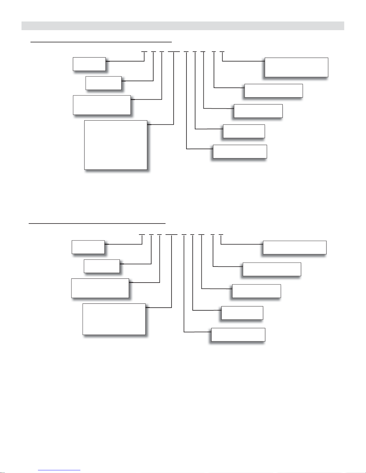
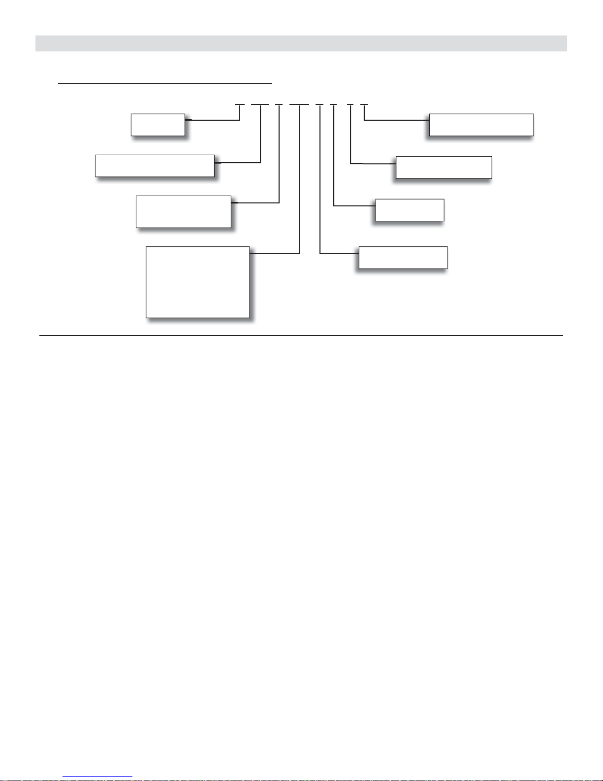
MODEL NUMBER IDENTIFICATION
OUTDOOR SINGLE ZONE HEAT PUMP UNITS
M P A 009 S 4 S - 1 P
Series Type
M = Mini-Split
Unit Type
P = Heat Pump
Major Design Sequence
A = 1st Generation
B = 2nd Generation
Nominal Cooling Capacity
009 = 0.75 tons
012 = 1 tons
018 = 1.5 tons
024 = 2 tons
030 = 2.5 tons
036 = 3 tons
048 = 4 tons
OUTDOOR MULTI-ZONE HEAT PUMP UNITS
M P A 036 S 4 M - 1 P
Voltage
L = 115V-1 phase-60hz
P = 208/230V-1 phase-60hz
Minor Design Sequence
1 = 1st Revision
Refrigerant Circuits
S = Single Circuit
Refrigerant Type
4 = R-410A
Cooling Effi ciency
S = Standard Effi ciency
Series Type
M = Mini-Split
Unit Type
P = Heat Pump
Major Design Sequence
A = 1st Generation
B = 2nd Generation
Nominal Cooling Capacity
018 = 1.5 tons
030 = 2.5 tons
036 = 3 tons
048 = 4 tons
Voltage
P = 208/230V-1 phase-60hz
Minor Design Sequence
1 = 1st Revision
Refrigerant Circuits
M = Multiple Circuits
Refrigerant Type
4 = R-410A
Cooling Effi ciency
S = Standard Effi ciency
Lennox Mini-Split Service Manual / Page 11
Page 12
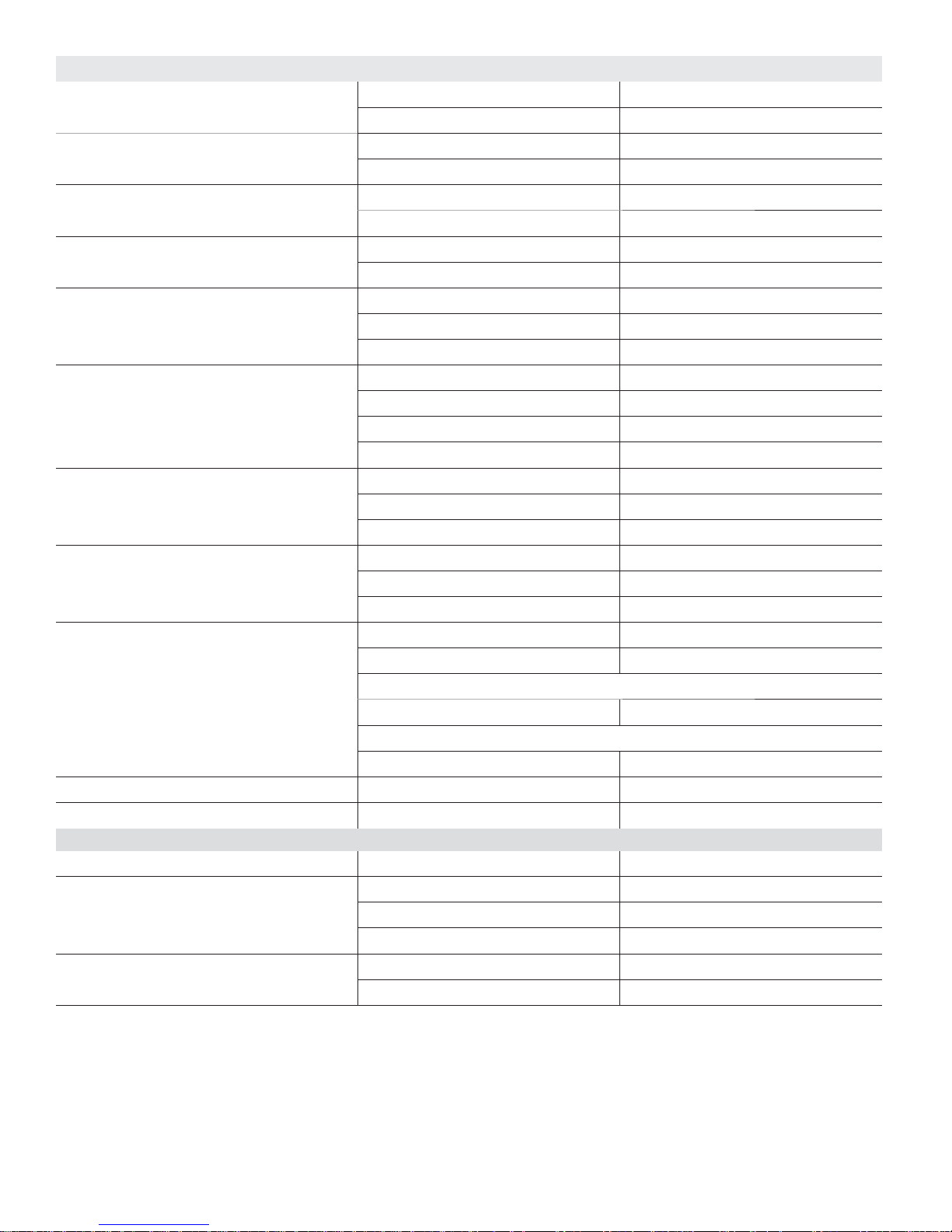
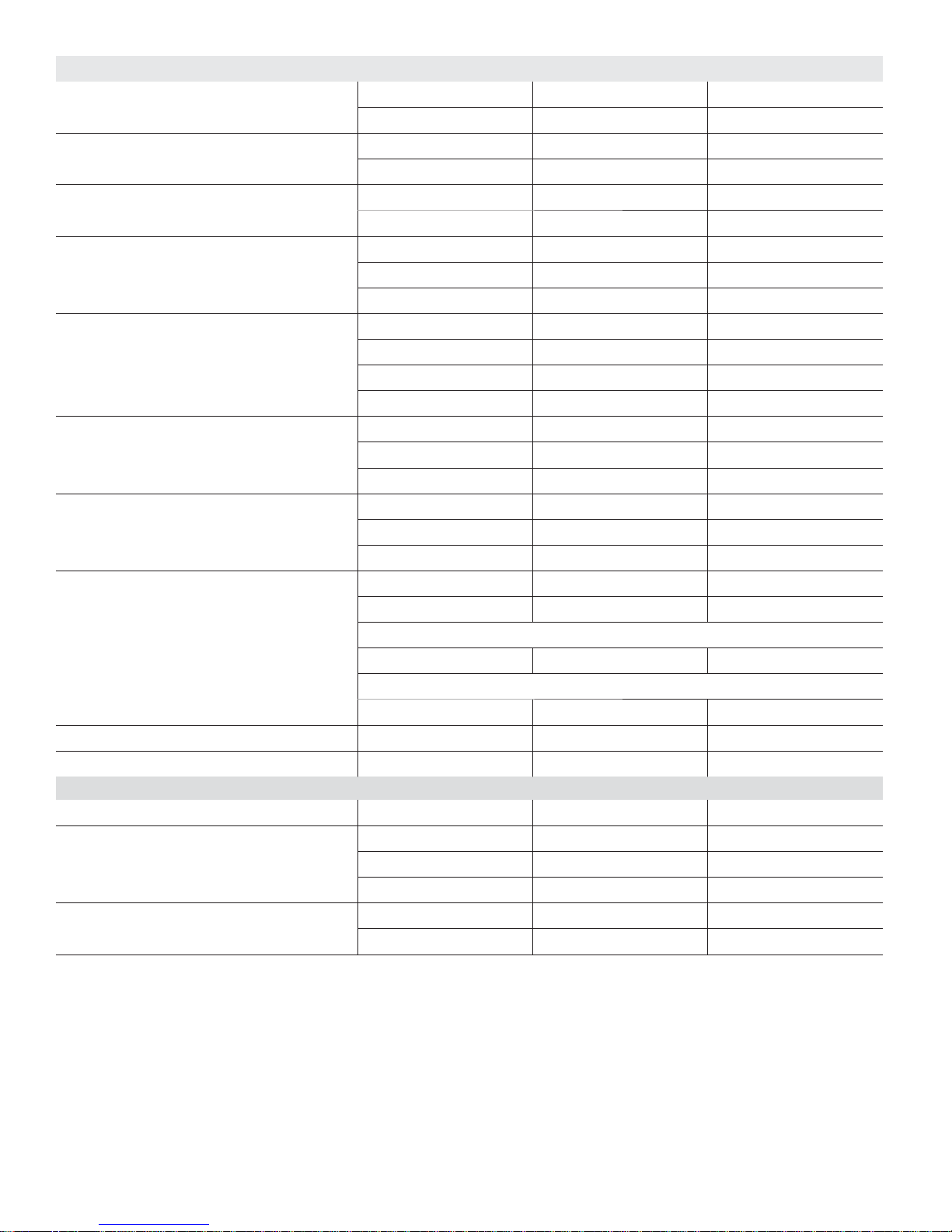
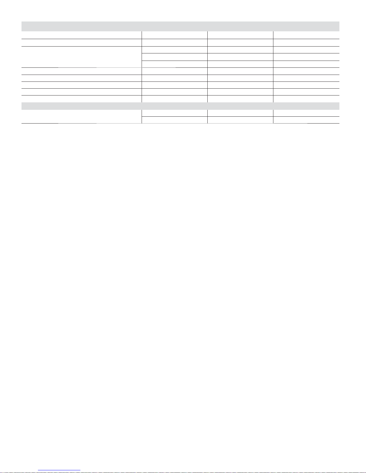
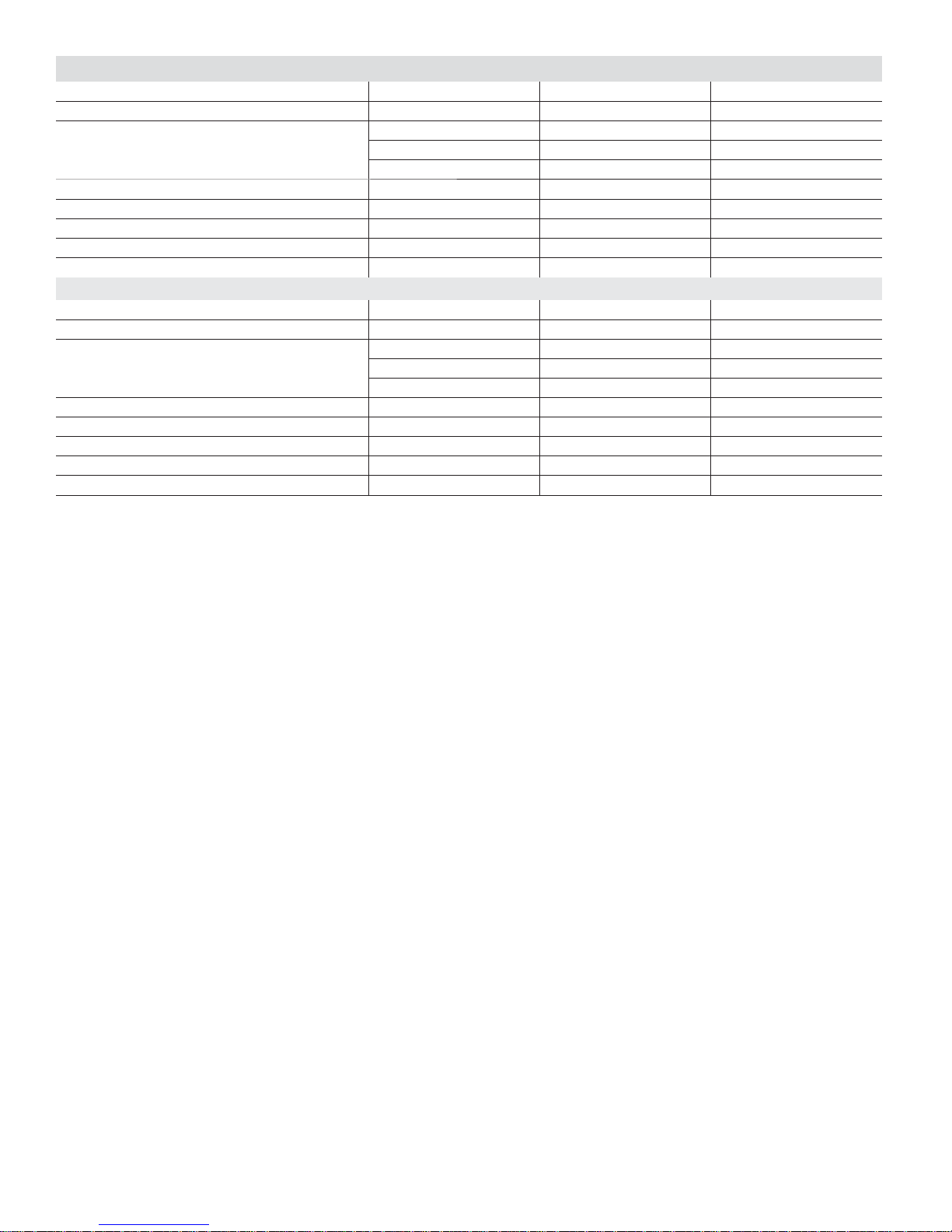
SPECIFICATIONS - 0.75 - 1 TON MPA OUTDOOR UNITS - 115V-1 PHASE
Nominal Size - Tons 0.75 1
Outdoor Unit Model No. MPA009S4S-1L MPA012S4S-1L
Input - Cooling/Heating (W) 620 / 870 888 / 1092
Rated current - Cooling/Heating (A) 5.4 / 7.6 7.7 / 9.5
Ambient Temperature
Operating Range - °F
Sound Data (dBA) Cooling 51 52
Refrigerant Charge furnished (R-410A) 2 lbs. 12 oz. 2 lbs. 12 oz.
Maximum line length with furnished charge - ft. 25 25
Additional charge required per ft. - oz. 0.16 0.16
Compressor No. and Type (1) Rotary (1) Rotary
Refrigerant oil type Ester Oil VG74 Ester Oil VG74
Refrigerant oil charge - oz. 12.5 12.5
Low ambient cut-off -13°F -13°F
Connections - in. Liquid/Gas pipe (fl are) 1/4 / 3/8 1/4 / 1/2
Maximum refrigerant pipe length - ft. 98 98
Max. difference in level of indoor unit - ft. 40 40
Outdoor
Fan
(No.) Diameter - in. (1) - 16.5 (1) - 16.5
Total air volume - cfm 1180 1180
Outdoor Coil Number of rows 2 2
Tube outside diameter - in. 1/4 1/4
Net face area - ft.
Design Pressure PSIG 550/340 550/340
Shipping Data Net/Shipping weight (lbs.) 83 / 88 83 / 88
Electrical Characteristics - 60 Hz - 1 Phase 115V 115V
1
Maximum Overcurrent Protection (amps) 20 20
2
Minimum circuit ampacity 15 15
Compressor Rated load amps 9 10
Outdoor Fan
Rated load amps 0.6 0.6
Motor
NOTE - Extremes of operating range are plus and minus 10% of line voltage.
1
HACR type circuit breaker or fuse.
2
Refer to National or Canadian Electrical Code manual to determine wire, fuse and disconnect size requirements.
Cooling 5 - 122 5 - 122
Heating –13 - 86 –13 - 86
Heating 54 54
rpm 850 850
Fins per inch 21 21
Fin type Hydrophilic aluminium
Tube type Rifl ed copper tubing
2
4.72 4.72
ELECTRICAL DATA
Output - W 40 40
Lennox Mini-Split Service Manual / Page 12
Page 13
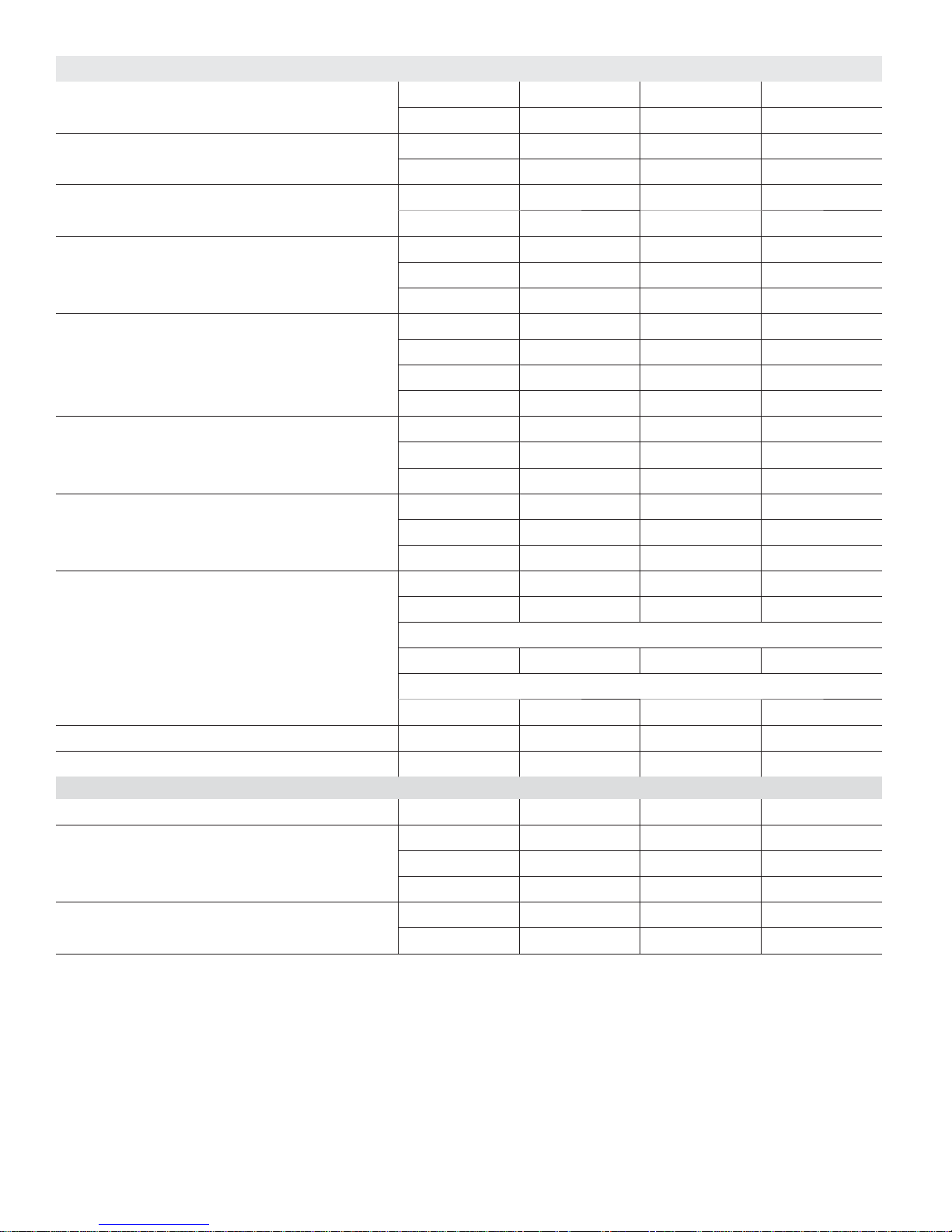
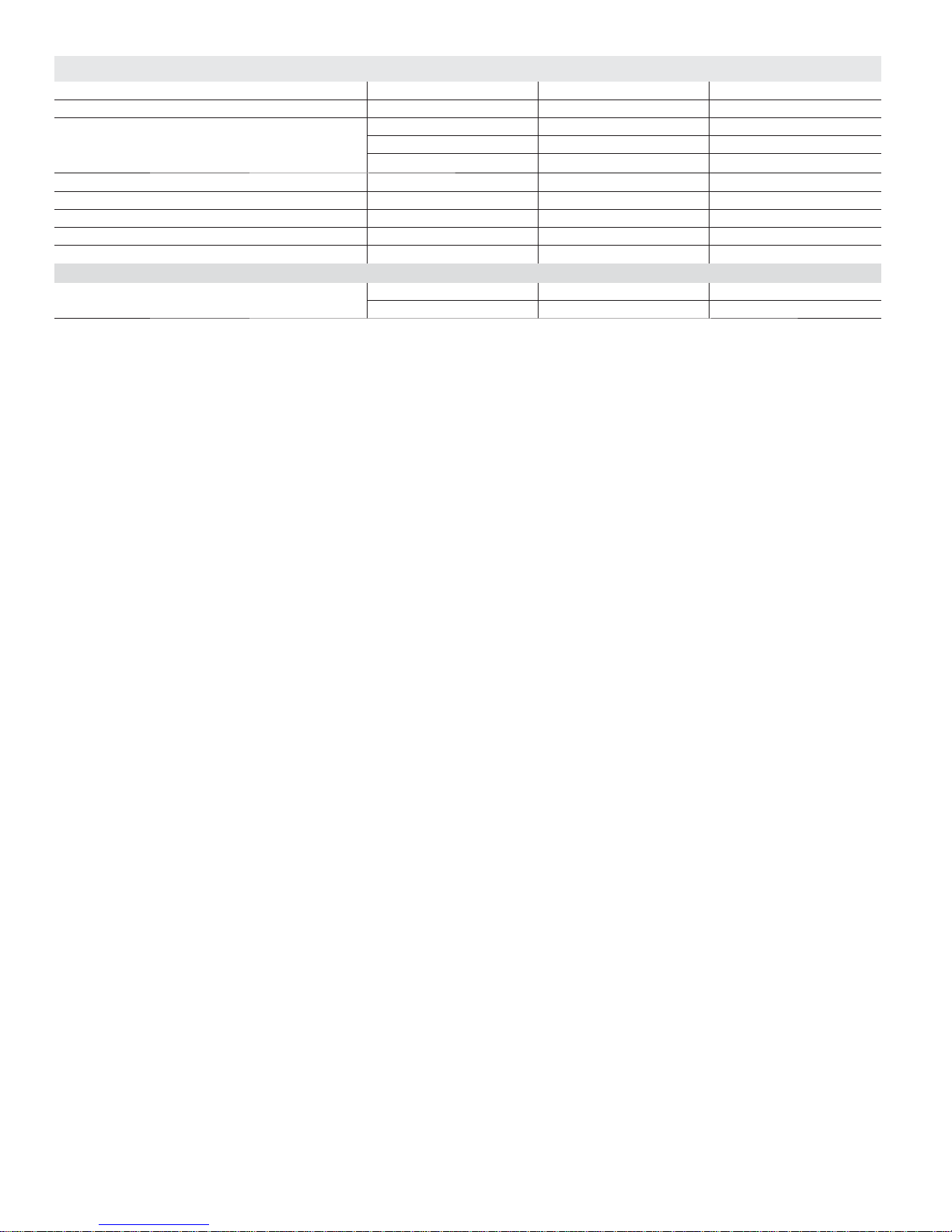
SPECIFICATIONS - 0.75 - 1.5 TON MPA OUTDOOR UNITS - 208/230V-1 PHASE
Nominal Size - Tons 0.75 1 1.5
Outdoor Unit Model No. MPA009S4S-1P MPA012S4S-1P MPA018S4S-1P
Ambient Temperature
Operating Range - °F
Sound Data (dBA) Cooling 53 54 61
Refrigerant Charge furnished (R-410A) 2 lbs. 12 oz. 2 lbs. 12 oz. 4 lbs. 3 oz.
Maximum line length with furnished charge - ft. 25 25 25
Additional charge required per ft. - oz. 0.16 0.16 0.16
Compressor No. and Type (1) Rotary (1) Rotary (1) Rotary
Refrigerant oil type Ester Oil VG74 Ester Oil VG74 Ester Oil VG74
Refrigerant oil charge - oz. 12.5 12.5 15.2
Low ambient cut-off -13°F -13°F -13°F
Connections - in. Liquid/Gas pipe (fl are) 1/4 / 3/8 1/4 / 1/2 1/4 / 1/2
Maximum refrigerant pipe length - ft. 98 98 98
Max. difference in level of indoor unit - ft. 40 40 66
Outdoor
Fan
(No.) Diameter - in. (1) - 16.5 (1) - 16.5 (1) - 18
Total air volume - cfm 1120 1180 1470
Outdoor Coil Number of rows 2 2 3
Tube outside diameter - in. 1/4 1/4 1/4
Net face area - ft.
Design Pressure PSIG 550/340 550/340 550/340
Shipping Data Net/Shipping weight (lbs.) 83 / 88 83 / 88 111 / 120
Electrical Characteristics - 60 Hz - 1 Phase 208/230V 208/230V 208/230V
1
Maximum Overcurrent Protection (amps) 15 15 20
2
Minimum circuit ampacity 15 15 13
Compressor Rated load amps 5.3 5.7 9.5
Outdoor Fan
Rated load amps 0.42 0.42 0.5
Motor
NOTE - Extremes of operating range are plus and minus 10% of line voltage.
1
HACR type circuit breaker or fuse.
2
Refer to National or Canadian Electrical Code manual to determine wire, fuse and disconnect size requirements.
Cooling 5 - 122 5 - 122 5 - 122
Heating –13 - 86 –13 - 86 –13 - 86
Heating 55 57 62
rpm 800 800 800
Fins per inch 21 21 18
Fin type Hydrophilic aluminium
Tube type Rifl ed copper tubing
2
4.72 4.72 5.42
ELECTRICAL DATA
Output - W 40 40 50
Lennox Mini-Split Service Manual / Page 13
Page 14
SPECIFICATIONS - 2 - 4 TON MPA OUTDOOR UNITS - 208/230V-1 PHASE
Nominal Size - Tons 2 2.5 3 4
Outdoor Unit Model No. MPA024S4S-1P MPA030S4S-1P MPA036S4S-1P MPA048S4S-1P
Ambient Temperature Operating
Range - °F
Sound Data (dBA) Cooling 59 59 62 63
Refrigerant Charge furnished (R-410A) 5 lbs. 3 oz. 6 lbs. 10 oz. 7 lbs. 13 oz. 9 lbs. 8 oz.
Maximum line length with furnished charge - ft. 25 25 25 25
Additional charge required per ft. - oz. 0.32 0.32 0.32 0.32
Compressor No. and Type Twin-Rotary Rotary Twin-Rotary Twin-Rotary
Refrigerant oil type Ester Oil VG74 FY50S FV50S FV50S
Refrigerant oil charge - oz. 27.7 36.1 36.1 47.3
Low ambient cut-off -13°F -13°F -13°F -13°F
Connections - in. Liquid/Gas pipe (fl are) 3/8 / 5/8 3/8 / 5/8 3/8 / 5/8 3/8 / 5/8
Maximum refrigerant pipe length - ft. 164 164 213 213
Max. difference in level of indoor unit - ft. 82 82 98 98
Outdoor
Fan
(No.) Diameter - in. (1) - 22 (1) - 22 (1) - 22 (2) - 20
Total air volume - cfm 2355 2530 2940 4240
Outdoor Coil Number of rows 2.6 2.6 2.6 2
Tube outside diameter - in. 1/4 1/4 3/8 5/16
Net face area - ft.
Design Pressure PSIG 550/340 550/340 550/340 550/340
Shipping Data Net/Shipping weight (lbs.) 134 / 144 158 / 170 161 / 183 220 / 251
Electrical Characteristics - 60 Hz - 1 Phase 208/230V 208/230V 208/230V 208/230V
1
Maximum Overcurrent Protection (amps) 25 30 50 60
2
Minimum circuit ampacity 15 20 30 35
Compressor Rated load amps 12 14 22 23.5
Outdoor Fan Motor Rated load amps 0.7 1.0 1.0 (2) 0.7
NOTE - Extremes of operating range are plus and minus 10% of line voltage.
1
HACR type circuit breaker or fuse.
2
Refer to National or Canadian Electrical Code manual to determine wire, fuse and disconnect size requirements.
Cooling 5 - 122 5 - 122 5 - 122 5 - 122
Heating –13 - 86 –13 - 86 –13 - 76 –13 - 76
Heating 63 61 65 65
rpm 850/750/700 950/800/750 950 860
Fins per inch 18 16 14 16
Fin type Hydrophilic aluminium
Tube type Rifl ed copper tubing
2
8.12 7.79 / 4.75 8.16 / 4.75 14.14
ELECTRICAL DATA
Output - W 120 120 120 (2) 85
Lennox Mini-Split Service Manual / Page 14
Page 15

SECTION 1.2 - MPA MULTI-ZONE
CONDENSING UNIT
Lennox Mini-Split Service Manual / Page 15
Page 16
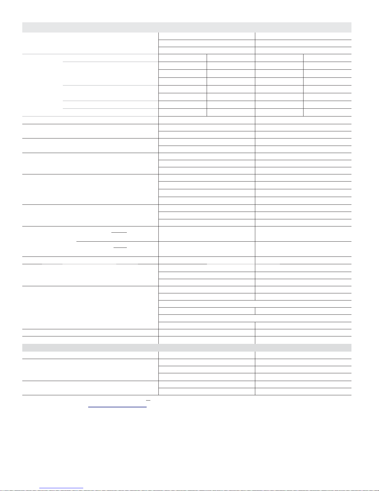
SPECIFICATIONS - 1.5 - 2.5 TON MPA OUTDOOR UNITS
Nominal Size - Tons 1.5 2.5
Outdoor Unit Model No. MPA018S4M-1P MPA030S4M-1P
Number of Zones 2 Up to 3
1
AHRI
Ratings
High Temperature Heating - Btuh 18,000 18,500 32,000 32,000
Low Temperature Heating - Btuh 10,900 11,000 20,000 20,000
AHRI Reference Number 8129621 8129607 8129624 8129613
Energy Star Yes N o
Ambient Temperature Range - °F Cooling 5 - 122 5 - 122
Sound Data (dBA) Cooling 57 59
Refrigerant Charge furnished (R-410A) 4 lbs. 4 oz. 6 lbs. 3 oz.
Maximum line length with furnished charge (per zone) - ft. 25 25
Additional charge required per ft. - oz. 0.161 0.161
Compressor No. and Type Twin-Rotary Twin-Rotary
Refrigerant oil charge - oz. 16.9 27.7
Connections - in. Liquid+Gas pipe (fl are) (2) 1/4 + (2) 3/8 (3) 1/4 + (3) 3/8
Maximum length for all rooms - ft. 98 148
Maximum length for one indoor unit - ft. 66 82
Maximum height
Outdoor unit higher than indoor
difference between
indoor unit and
outdoor unit
Outdoor unit lower than indoor
Maximum difference in level between indoor units - ft. 33 33
Outdoor
Fan
Total air volume - cfm 1470 2060
Outdoor Coil Number of rows 2 1.6
Tube outside diameter - in. 3/8 3/8
Design Pressure PSIG 550/340 550/340
Shipping Data Net/Shipping weight (lbs.) 106 / 115 144 / 155
Electrical Characteristics - 60 Hz - 1 Phase 208/230V 208/230V
2
Maximum Overcurrent Protection (amps) 20 25
3
Minimum circuit ampacity 15 19
Compressor Rated load amps 10 12
Outdoor Fan Motor Rated load amps 0.74 0.90
NOTE - Per AHRI, the certifi ed ratings for systems are valid for all combinations of indoor units with the specifi c outdoor units listed above and in the AHRI Directory of
Certifi ed Equipment. Please visit http://www.ahridirectory.org for further details and latest updates.
1
Ratings are AHRI certifi ed to AHRI Standard 210/240-2008;
• Cooling Ratings - 80°F dry bulb/67°F wet bulb entering indoor coil air and 95°F dry bulb/75°F wet bulb outdoor air temperature.
• High Temperature Heating Ratings - 70°F dry bulb/60°F wet bulb entering indoor coil air and 47°F dry bulb/43°F wet bulb outdoor air temperature.
• Low Temperature Heating Ratings - 70°F dry bulb/60°F wet bulb entering indoor coil air and 17°F dry bulb/15°F wet bulb outdoor air temperature.
NOTE - Extremes of operating range are plus and minus 10% of line voltage.
2
HACR type circuit breaker or fuse.
3
Refer to National or Canadian Electrical Code manual to determine wire, fuse and disconnect size requirements.
NOTE - Adaptors are furnished for the gas pipe connections:
018 - (2) 3/8 x 1/2 in.
030 - (3) 3/8 x 1/2 in.
System Type Ducted Non-Ducted Ducted Non-Ducted
Cooling - Btuh 17,000 18,000 27,000 25,000
SEER 18.00 21.00 16.50 22.00
EER 12.50 12.50 9.50 12.50
HSPF (Region IV) 8.5 9.6 8.8 9.6
Heating –13 - 76 –13 - 76
Heating 62 62
Refrigerant oil type ESTER OIL VG74 ESTER OIL VG74
Low ambient cut-off
33 33
unit - ft.
49 49
unit - ft.
(No.) Diameter - in. (1) - 18 (1) - 22
rpm 750 850
Fins per inch 14 15
Fin type Hydrophilic aluminium
Tube type Rifl ed copper tubing
Net face area - ft.
2
4.9 6.42
ELECTRICAL DATA
Output - W 50 120
Lennox Mini-Split Service Manual / Page 16
Page 17
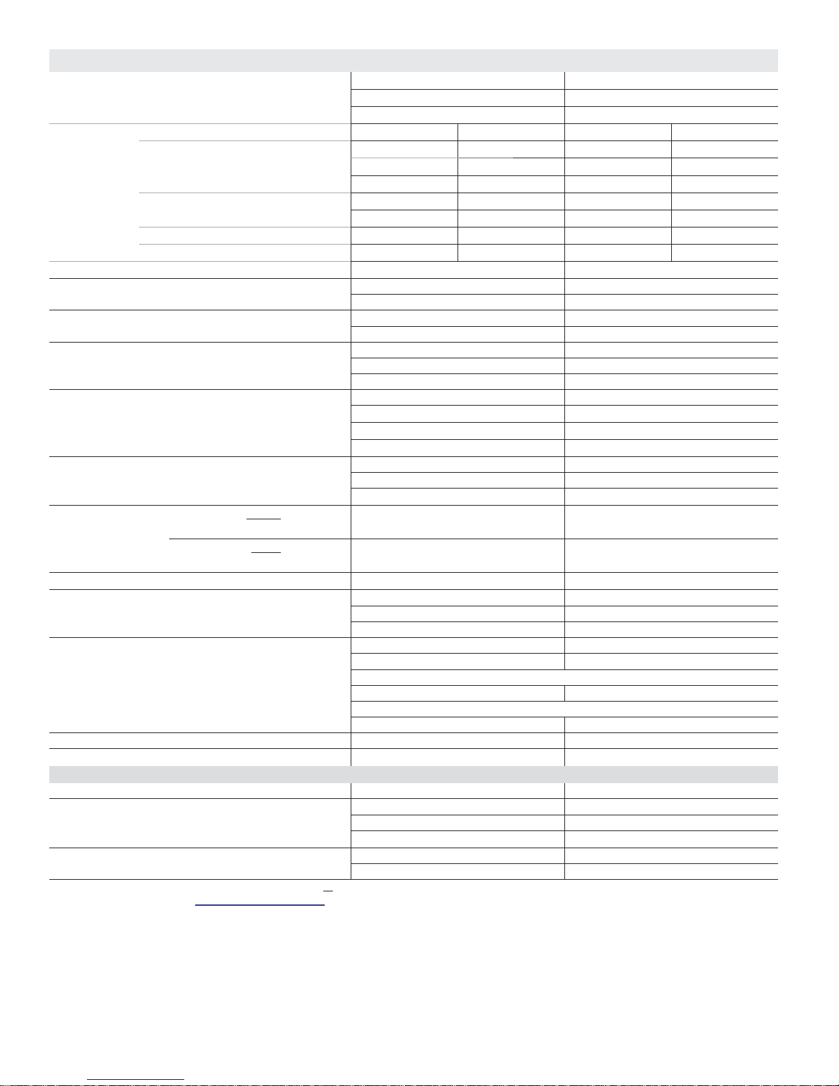
SPECIFICATIONS - 3 - 4 TON MPA OUTDOOR UNITS
Nominal Size - Tons 3 4
Outdoor Unit Model No. MPA036S4M-1P MPA048S4M-1P
Number of Zones Up to 4 Up to 5
1
AHRI
Ratings
High Temperature Heating - Btuh 36,000 36,000 51,000 49,000
Low Temperature Heating - Btuh 24,400 23,400 31,800 31,200
AHRI Reference Number 8129615 8129614 8129617 8129616
Energy Star Yes N o
Ambient Temperature Range - °F Cooling 5 - 122 5 - 122
Sound Data (dBA) Cooling 62 58
Refrigerant Charge furnished (R-410A) 7 lbs. 15 oz. 9 lbs. 8 oz.
Maximum line length with furnished charge (per zone) - ft. 25 25
Additional charge required per ft. - oz. 0.161 0.161
Compressor No. and Type Twin-Rotary Twin-Rotary
Refrigerant oil charge - oz. 36.2 47.3
Connections - in. Liquid+Gas+Gas pipe (fl are) (4) 1/4 + (3) 3/8 + (1) 1/2 (5) 1/4 + (3) 3/8 + (2) 1/2
Maximum length for all rooms - ft. 197 246
Maximum length for one indoor unit - ft. 98 98
Maximum height
Outdoor unit higher than indoor
difference between
indoor unit and
Outdoor unit lower than indoor
outdoor unit
Maximum difference in level between indoor units - ft. 33 33
Outdoor
Fan
Total air volume - cfm 2240 (2) 4240
Outdoor Coil Number of rows 2.6 2
Tube outside diameter - in. 5/16 5/16
Design Pressure PSIG 550/340 550/340
Shipping Data Net/Shipping weight (lbs.) 162 / 174 218 / 245
Electrical Characteristics - 60 Hz - 1 Phase 208/230V 208/230V
2
Maximum Overcurrent Protection (amps) 45 50
3
Minimum circuit ampacity 27 29
Compressor Rated load amps 19.5 22
Outdoor Fan Motor Rated load amps 1.30 (2) 0.9
NOTE - Per AHRI, the certifi ed ratings for systems are valid for all combinations of indoor units with the specifi c outdoor units listed above and in the AHRI Directory of
Certifi ed Equipment. Please visit http://www.ahridirectory.org for further details and latest updates.
1
Ratings are AHRI certifi ed to AHRI Standard 210/240-2008;
• Cooling Ratings - 80°F dry bulb/67°F wet bulb entering indoor coil air and 95°F dry bulb/75°F wet bulb outdoor air temperature.
• High Temperature Heating Ratings - 70°F dry bulb/60°F wet bulb entering indoor coil air and 47°F dry bulb/43°F wet bulb outdoor air temperature.
• Low Temperature Heating Ratings - 70°F dry bulb/60°F wet bulb entering indoor coil air and 17°F dry bulb/15°F wet bulb outdoor air temperature.
NOTE - Extremes of operating range are plus and minus 10% of line voltage.
2
HACR type circuit breaker or fuse.
3
Refer to National or Canadian Electrical Code manual to determine wire, fuse and disconnect size requirements.
NOTE - Adaptors are furnished for the gas pipe connections:
036 - (3) 3/8 x 1/2 in. and (1) 1/2 x 3/8 in.
048 - (3) 3/8 x 1/2 in., (2) 1/2 x 3/8 in., (2) 1/4 x 3/8 in. and (2) 1/2 x 5/8 in.
System Type Ducted Non-Ducted Ducted Non-Ducted
Cooling - Btuh 34,000 36,000 42,000 42,000
SEER 15.00 18.00 18.00 20.00
EER 8.20 8.80 11.00 12.50
HSPF (Region IV) 9.3 10.0 9.5 10.0
Heating –13 - 76 –13 - 76
Heating 64 62
Refrigerant oil type FV50S FV50S
Low ambient cut-off
33 33
unit - ft.
49 49
unit - ft.
(No.) Diameter - in. (1) - 22 (2) - 20
rpm 950 (2) 800
Fins per inch 15 15
Fin type Hydrophilic aluminium
Tube type Rifl ed copper tubing
Net face area - ft.
2
6.42 14.33
ELECTRICAL DATA
Output - W 120 (2) 85
Lennox Mini-Split Service Manual / Page 17
Page 18

SECTION 2 - INDOOR UNIT DATA
Lennox Mini-Split Service Manual / Page 18
Page 19
SECTION 2.1 - M22A COMPACT CASSETTE
UNIT
Lennox Mini-Split Service Manual / Page 19
Page 20
MODEL NUMBER IDENTIFICATION
CASSETTE NON-DUCTED INDOOR UNITS
M 22 A 012 S 4 - 1 P
Series Type
M = Mini-Split
Unit Type
22 = 2x2 Cassette Non-Ducted Unit
33 = 3x3 Cassette Non-Ducted Unit
Major Design Sequence
A = 1st Generation
B = 2nd Generation
Nominal Cooling Capacity
009 = .75 tons
012 = 1 tons
018 = 1.5 tons
024 = 2 tons
036 = 3 tons
048 = 4 tons
Voltage
P = 208/230V-1 phase-60hz
Minor Design Sequence
1 = 1st Revision
Refrigerant Type
4 = R-410A
Cooling Effi ciency
S = Standard Effi ciency
Lennox Mini-Split Service Manual / Page 20
Page 21
SPECIFICATIONS - CASSETTE INDOOR UNITS - M22A009-018
Model No. M22A009S4-1P M22A012S4-1P M22A018S4-1P
Nominal Tons 0.75 1 1.5
Power Supply - 60 hz - 1 phase 208/230V 208/230V 208/230V
Rated load amps 0.9 1.0 1.5
Output (W) 46 46 46
Air Volume - cfm (High/Medium/Low) 380/320/260 400/340/280 420/350/290
Sound Data (dBA) - Low/Medium/High 37/39/41 35/38/41 41/43/46
Piping Connections - Liquid/Gas - o.d. - fl are - in. 1/4 / 3/8 1/4 / 1/2 1/4 / 1/2
Drain connection o.d. - in. 1 1 1
Net/Shipping weights - lbs. Body 36 / 42 36 / 42 40 / 47
REQUIRED COMPONENTS - ORDERED SEPARATELY
Cassette Panel 13X04 (M0STAT62Q-1) 13X04 (M0STAT62Q-1) 13X04 (M0STAT62Q-1)
Net/Shipping weights - lbs. 6 / 10 6 / 10 6 / 10
Lennox Mini-Split Service Manual / Page 21
Page 22

SOUND DATA
Lennox Mini-Split Service Manual / Page 22
Page 23

AIR THROW DATA
Lennox Mini-Split Service Manual / Page 23
Page 24

SECTION 2.2 - M33A CASSETTE UNIT
Lennox Mini-Split Service Manual / Page 24
Page 25

MODEL NUMBER IDENTIFICATION
CASSETTE NON-DUCTED INDOOR UNITS
M 33 A 012 S 4 - 1 P
Series Type
M = Mini-Split
Unit Type
22 = 2x2 Cassette Non-Ducted Unit
33 = 3x3 Cassette Non-Ducted Unit
Major Design Sequence
A = 1st Generation
B = 2nd Generation
Nominal Cooling Capacity
009 = .75 tons
012 = 1 tons
018 = 1.5 tons
024 = 2 tons
036 = 3 tons
048 = 4 tons
Voltage
P = 208/230V-1 phase-60hz
Minor Design Sequence
1 = 1st Revision
Refrigerant Type
4 = R-410A
Cooling Effi ciency
S = Standard Effi ciency
Lennox Mini-Split Service Manual / Page 25
Page 26
SPECIFICATIONS - CASSETTE INDOOR UNITS - M33A024-048
Model No. M33A024S4-1P M33A036S4-1P M33A048S4-1P
Nominal Tons 2 3 4
Power Supply - 60 hz - 1 phase 208/230V 208/230V 208/230V
Rated load amps 2 1.5 1.6
Output (W) 42 124 124
Air Volume - cfm (High/Medium/Low) 820/740/590 1060/940/820 1190/1000/850
Sound Data (dBA) - Low/Medium/High 43/47/51 44/47/52 44/48/52
Piping Connections - Liquid/Gas - o.d. - fl are - in. 3/8 / 5/8 3/8 / 5/8 3/8 / 5/8
Drain connection o.d. - in. 1-1/4 1-1/4 1-1/4
Net/Shipping weights - lbs. Body 46 / 53 56 / 63 64 / 74
REQUIRED COMPONENTS - ORDERED SEPARATELY
Cassette Panel 13X05 (M0STAT63Q-1) 13X05 (M0STAT63Q-1) 13X05 (M0STAT63Q-1)
Net/Shipping weights - lbs. 12 / 18 12 / 18 12 / 18
Lennox Mini-Split Service Manual / Page 26
Page 27
SECTION 2.3 - MMDA DUCTED UNIT
Lennox Mini-Split Service Manual / Page 27
Page 28
MODEL NUMBER IDENTIFICATION
MEDIUM STATIC DUCTED INDOOR UNITS
M MD A 012 S 4 - 1 P
Series Type
M = Mini-Split
Unit Type
MD = Medium Static Ducted Unit
Major Design Sequence
A = 1st Generation
B = 2nd Generation
Nominal Cooling Capacity
009 = .75 tons
012 = 1 tons
018 = 1.5 tons
024 = 2 tons
036 = 3 tons
048 = 4 tons
Voltage
P = 208/230V-1 phase-60hz
Minor Design Sequence
1 = 1st Revision
Refrigerant Type
4 = R-410A
Cooling Effi ciency
S = Standard Effi ciency
Lennox Mini-Split Service Manual / Page 28
Page 29
SPECIFICATIONS - MEDIUM STATIC DUCTED INDOOR UNITS - 009-018
Model No. MMDA009S4-1P MMDA012S4-1P MMDA018S4-1P
Nominal Tons 0.75 1 1.5
Power Supply - 60 hz - 1 phase 208/230V 208/230V 208/230V
Rated load amps 0.9 1 1.5
Output (W) 55 55 90
Air Volume - cfm (High/Medium/Low) 400/330/270 400/330/270 485/380/320
Sound Data (dBA) - Low/Medium/High 31/34/37 32/36/39 31/33/35
Piping Connections - Liquid/Gas - o.d. - fl are - in. 1/4 / 3/8 1/4 / 1/2 1/4 / 1/2
Drain connection o.d. - in. 1 1 1
Net/Shipping weights - lbs. 40 / 51 40 / 51 51 / 64
SPECIFICATIONS - MEDIUM STATIC DUCTED INDOOR UNITS - 024-048
Model No. MMDA024S4-1P MMDA036S4-1P MMDA048S4-1P
Nominal Tons 2 3 4
Power Supply - 60 hz - 1 phase 208/230V 208/230V 208/230V
Rated load amps 2 1.5 1.8
Output (W) 90 150 240
Air Volume - cfm (High/Medium/Low) 800/675/585 910/800/630 1280/1100/920
Sound Data (dBA) - Low/Medium/High 45/47/50 45/49/53 41/44/47
Piping Connections - Liquid/Gas - o.d. - fl are - in. 3/8 / 5/8 3/8 / 5/8 3/8 / 5/8
Drain connection o.d. - in. 1 1 1
Net/Shipping weights - lbs. 58 / 69 78 / 93 100 / 117
Lennox Mini-Split Service Manual / Page 29
Page 30

BLOWER DATA
MMDA009S4-1P, MMDA012S4-1P
Low Speed
0.20
0.18
0.16
0.14
0.12
0.10
0.08
External Static Pressure - in. w.g.
0.06
0.04
0.02
0.00
160 260 360
Air Volume - cfm Air Volume - cfm
Medium Speed
0.20
0.15
0.10
External Static Pressure - in. w.g.
0.05
0.00
150 200 250 300 350 400
High Speed
0.30
0.25
0.20
0.15
0.10
External Static Pressure - in. w.g.
0.05
0.00
170 220 270 320 370 420 470
Air Volume - cfm
MMDA018S4-1P
Low Speed
0.16
0.14
0.12
0.10
0.08
0.06
External Static Pressure - in. w.g.
0.04
0.02
0.00
150 250 350 450
Air Volume - cfm Air Volume - cfm
Medium Speed
0.24
0.22
0.20
0.18
0.16
0.14
0.12
0.10
0.08
External Static Pressure - in. w.g.
0.06
0.04
0.02
0.00
130 230 330 430 530
High Speed
0.28
0.26
0.24
0.22
0.20
0.18
0.16
0.14
0.12
0.10
External Static Pressure - in. w.g.
0.08
0.06
0.04
0.02
0.00
150 250 350 450 550 650
Air Volume - cfm
Lennox Mini-Split Service Manual / Page 30
Page 31

MMDA024S4-1P
Low Speed
0.40
0.35
0.30
0.25
0.20
0.15
External Static Pressure - in. w.g.
0.10
0.05
0.00
260360460560660760860960
Air Volume - cfm Air Volume - cfm
Medium Speed
0.50
0.45
0.40
0.35
0.30
0.25
0.20
External Static Pressure - in. w.g.
0.15
0.10
0.05
0.00
250 450 650 850 1050
High Speed
0.45
0.40
0.35
0.30
0.25
0.20
0.15
External Static Pressure - in. w.g.
0.10
0.05
0.00
500 600 700 800 900 1000 1100 1200
Air Volume - cfm
MMDA036S4-1P
Low Speed
0.40
0.35
0.30
0.25
0.20
0.15
External Static Pressure - in. w.g.
0.10
0.05
Medium Speed
0.40
0.35
0.30
0.25
0.20
0.15
External Static Pressure - in. w.g.
0.10
0.05
High Speed
0.50
0.45
0.40
0.35
0.30
0.25
0.20
External Static Pressure - in. w.g.
0.15
0.10
0.05
0.00
400 500 600 700 800 900 1000 1100 1200
Air Volume - cfm Air Volume - cfm
0.00
600 700 800 900 1000 1100 1200 1300
0.00
400 600 800 1000 1200
Air Volume - cfm
Lennox Mini-Split Service Manual / Page 31
Page 32

MMDA048S4-1P,
Low Speed
0.40
0.35
0.30
0.25
0.20
0.15
External Static Pressure - in. w.g.
0.10
0.05
0.00
700 900 1100 1300 1500 1700
Air Volume - cfm Air Volume - cfm
Medium Speed
0.45
0.40
0.35
0.30
0.25
0.20
0.15
External Static Pressure - in. w.g.
0.10
0.05
0.00
700 900 1100 1300 1500
High Speed
0.50
0.45
0.40
0.35
0.30
0.25
0.20
0.15
External Static Pressure - in. w.g.
0.10
0.05
0.00
700 900 1100 1300 1500 1700
Air Volume - cfm
Lennox Mini-Split Service Manual / Page 32
Page 33

SECTION 2.4 - MWMA WALL MOUNTED UNIT
Lennox Mini-Split Service Manual / Page 33
Page 34

MODEL NUMBER IDENTIFICATION
WALL-MOUNTED INDOOR UNITS
M WM A 012 S 4 - 1 P
Series Type
M = Mini-Split
Unit Type
WM = Wall-Mounted Non-Ducted Unit
Major Design Sequence
A = 1st Generation
B = 2nd Generation
Nominal Cooling Capacity
009 = .75 tons
012 = 1 tons
018 = 1.5 tons
024 = 2 tons
030 = 2.5 tons
Voltage
L = 115V-1 phase-60hz
P = 208/230V-1 phase-60hz
Minor Design Sequence
1 = 1st Revision
Refrigerant Type
4 = R-410A
Cooling Effi ciency
S = Standard Effi ciency
Lennox Mini-Split Service Manual / Page 34
Page 35

SPECIFICATIONS - WALL-MOUNTED INDOOR UNITS - 009-012
Model No. MWMA009S4-1L MWMA009S4-1P MWMA012S4-1L MWMA012S4-1P
Nominal Tons 0.75 0.75 1 1
Power Supply - 60 hz - 1 phase 115V 208/230V 115V 208/230V
Rated load amps 0.19 0.06 0.19 0.06
Output (W) 20 20 20 20
Air Volume - cfm (High/Medium/Low) 340/260/205 340/260/205 340/260/205 340/260/205
Sound Data (dBA) - Low/Medium/High 29/36.4/43.7 29.1/36.2/43.3 28.9/36.4/43.9 29.3/36.2/43
Piping Connections - Liquid/Gas - o.d. - fl are - in. 1/4 / 3/8 1/4 / 3/8 1/4 / 1/2 1/4 / 1/2
Drain connection o.d. - in. 1111
Net/Shipping weights - lbs. 20 / 26 20 / 26 20 / 26 20 / 26
SPECIFICATIONS - WALL-MOUNTED INDOOR UNITS - 018-030
Model No. MWMA018S4-1P MWMA024S4-1P MWMA030S4-1P
Nominal Tons 1.5 2 2.5
Power Supply - 60 hz - 1 phase 208/230V 208/230V 208/230V
Rated load amps 0.13 0.3 0.3
Output (W) 58 60 60
Air Volume - cfm (High/Medium/Low) 595/460/355 750/690/565 750/690/565
Sound Data (dBA) - Low/Medium/High 30.5/38.6/46.6 39.4/44.7/50 39/44.9/50.7
Piping Connections - Liquid/Gas - o.d. - fl are - in. 1/4 / 1/2 3/8 / 5/8 3/8 / 5/8
Drain connection o.d. - in. 1 1 1
Total refrigerant pipe length - ft. 98 98 164
Net/Shipping weights - lbs. 27 / 35 40 / 51 40 / 51
Lennox Mini-Split Service Manual / Page 35
Page 36

SECTION 2.5 - MCFA CEILING/FLOOR UNIT
Lennox Mini-Split Service Manual / Page 36
Page 37

MODEL NUMBER IDENTIFICATION
CEILING/FLOOR NON-DUCTED INDOOR UNITS
M CF A 012 S 4 - 1 P
Series Type
M = Mini-Split
Unit Type
CF = Ceiling/Floor Non-Ducted
Major Design Sequence
A = 1st Generation
B = 2nd Generation
Nominal Cooling Capacity
012 = 1 tons
018 = 1.5 tons
024 = 2 tons
036 = 3 tons
048 = 4 tons
Voltage
P = 208/230V-1 phase-60hz
Minor Design Sequence
1 = 1st Revision
Refrigerant Type
4 = R-410A
Cooling Effi ciency
S = Standard Effi ciency
Lennox Mini-Split Service Manual / Page 37
Page 38

SPECIFICATIONS - CEILING/FLOOR MOUNT INDOOR UNITS - 012-024
Model No. MCFA012S4-1P MCFA018S4-1P MCFA024S4-1P
Nominal Tons 1 1.5 2
Power Supply - 60 hz - 1 phase 208/230V 208/230V 208/230V
Rated load amps 1 1 1
Output (W) 55 55 55
Air Volume - cfm (High/Medium/Low) 470/360/290 470/360/290 880/770/650
Sound Data (dBA) - Low/Medium/High 33/38/44 34/38/46 52/55/58.5
Piping Connections - Liquid/Gas - o.d. - fl are - in. 1/4 / 1/2 1/4 / 1/2 3/8 / 5/8
Drain connection o.d. - in. 1 1 1
Net/Shipping weights - lbs. 47 / 61 53 / 67 56 / 67
SPECIFICATIONS - CEILING/FLOOR MOUNT INDOOR UNITS - 036-048
Model No. MCFA036S4-1P MCFA048S4-1P
Nominal Tons 3 4
Power Supply - 60 hz - 1 phase 208/230V 208/230V
Rated load amps 1 2
Output (W) 115 90
Air Volume - cfm (High/Medium/Low) 970/820/560 1350/1120/1000
Sound Data (dBA) - Low/Medium/High 41/48/55 52/54/57
Piping Connections - Liquid/Gas - o.d. - fl are - in. 3/8 / 5/8 3/8 / 5/8
Drain connection o.d. - in. 1 1
Net/Shipping weights - lbs. 67 / 78 84 / 97
Lennox Mini-Split Service Manual / Page 38
Page 39

SECTION 3 - INSTALLATION DIMENSIONS OF
OUTDOOR UNITS
Lennox Mini-Split Service Manual / Page 39
Page 40

SECTION 3.1 - SINGLE ZONE INSTALLATION
DIMENSIONS
Lennox Mini-Split Service Manual / Page 40
Page 41

MPA009S4S, MPA012S4S, MPA018S4S Dimensions
O
FRONT VIEW SIDE VIEW
2-1/2 (64)
31-7/8 (809)
21-5/8 (549)
22
(559)
TOP VIEW
FRONT VIEW
33-1/4 (845)
22 (559)
11-3/8 (289)
27-1/2
(699)
2-7/8 (73)
13-3/4 (349)
12-3/4 (324)
SIDE VIEW
P VIEW
T
13 (330)
12-3/4 (324)
Lennox Mini-Split Service Manual / Page 41
Page 42

MPA024S4S, MPA030S4S, MPA036S4S Dimensions
31-7/8
(810)
15-1/2
(394)
FRONT VIEW
37-1/4 (946)
25-1/4 (641)
TOP VIEW
3-3/8 (86)
16 (406)
15-1/8 (384)
17-5/8 (448)
SIDE VIEW
Lennox Mini-Split Service Manual / Page 42
Page 43

MPA048S4S Dimensions
25 (635)
15-3/8
(391)
14-1/2
(369)
36-7/8 (937)
TOP VIEW
16
(406)
3-3/8
(86)
53-3/4
(1365)
SIDE VIEW
FRONT VIEW
BOTTOM VIEW
SIDE VIEW
Lennox Mini-Split Service Manual / Page 43
Page 44

SECTION 3.2 - MULTI-ZONE INSTALLATION
DIMENSIONS
Lennox Mini-Split Service Manual / Page 44
Page 45

MPA018S4M Dimensions
MPA018S4M
12-3/4
(324)
22 (559)
TOP VIEW
12-1/4
(312)
27-3/8
(695)
13-1/8
(333)
14-1/8
(359)
33-1/8 (841) 2-3/4 (70)
FRONT VIEW SIDE VIEW
Lennox Mini-Split Service Manual / Page 45
Page 46

MPA030S4M, MPA036S4M Dimensions
31-7/8
(810)
15-1/2
(394)
FRONT VIEW
37-1/4 (946)
25-1/4 (641)
TOP VIEW
3-3/8 (86)
16 (406)
15-1/8 (384)
17-5/8 (448)
SIDE VIEW
Lennox Mini-Split Service Manual / Page 46
Page 47

MPA048S4M Dimensions
25 (635)
15-3/8
(391)
14-1/2
(369)
36-7/8 (937)
TOP VIEW
16
(406)
3-3/8
(86)
53-3/4
(1365)
SIDE VIEW
FRONT VIEW
BOTTOM VIEW
SIDE VIEW
Lennox Mini-Split Service Manual / Page 47
Page 48

SECTION 3.3 - MPA OUTDOOR UNIT
CLEARANCES
Lennox Mini-Split Service Manual / Page 48
Page 49

Outdoor Unit Clearances
A
C A
A
Air Inlet
A
B
Air Outlet
Air Inlet
A
C A
1
Dimension in. mm
1
Clearance dimensions apply to both single-fan cabinets and
double-fan cabinets.
2
Minimum rear clearance can be 6 inches (152 mm) when
mounted on brackets and with no obstructions on the other
three sides.
B
Air Outlet
A 24 610
B 79 2007
2
C 12 305
Lennox Mini-Split Service Manual / Page 49
Page 50

SECTION 4 - INSTALLATION DIMENSIONS OF
INDOOR UNITS
Lennox Mini-Split Service Manual / Page 50
Page 51

SECTION 4.1 - M22A COMPACT CASSETTE
Lennox Mini-Split Service Manual / Page 51
Page 52

M22A Indoor Cassette Units Dimensions
M22A009S4, M22A012S4, M22A018S4
DRAIN
CONNECTION
GAS
PIPE
LIQUID
PIPE
SIDE VIEW
10-3/8
(264)
5-3/4
(146)
6 in. (152 mm)
Diameter
LEFT SIDE VIEW
11-1/4
(286)
INSTALLATION
HANGERS
LEVELING
ADJUSTMENT
NUT (4)
CEILING
AIR
OUTLET
21-1/2 (546)
22-1/2 (572)
BOTTOM VIEW (Body)
DIFFUSER
PANEL
AIR
INLET
20-5/8
(524)
AIR
OUTLET
5-3/4
(146)
6 in. (152 mm)
Diameter
RIGHT SIDE VIEW
11-1/4
(286)
22-1/2
(572)
25-1/2
(648)
23-5/8 (600)
(Ceiling Opening)
SIDE VIEW
25-1/2 (648)
BOTTOM VIEW (Panel)
Lennox Mini-Split Service Manual / Page 52
Page 53

M22A Indoor Cassette Units Clearances
INSTALLATION
HANGERS
LEVELING
ADJUSTMENT
NUT (4)
CEILING
AIR
OUTLET
(914 mm)
DIFFUSER
36”
PANEL
AIR
INLET
23-5/8 (600)
(Ceiling Opening)
36”
(914 mm)
AIR
OUTLET
36”
(914 mm)
Minimum Clearance from Structural Ceiling to Drop Ceiling:
M22A009, M22A012, M22A018 -- 10-1/4” (260 mm)
Minimum Clearance to Floor - 98-1/2” (2500 mm)
36”
(914 mm)
Lennox Mini-Split Service Manual / Page 53
Page 54

SECTION 4.2 - M33A CASSETTE UNIT
Lennox Mini-Split Service Manual / Page 54
Page 55

M33A Indoor Units Dimensions
M33A024S4, M33A036S4, M33A048S4
GAS
PIPE
LIQUID
PIPE
30-3/4
(781)
A
33-1/8
(841)
DRAIN
CONNECTION
AIR
OUTLET
37-3/8
(949)
26-3/4 (679)
33-1/8 (841)
BOTTOM VIEW (Body)
DIFFUSER
PANEL
AIR
INLET
SIDE VIEW
RIGHT SIDE VIEW
AIR
OUTLET
BOTTOM VIEW (Panel)
37-3/8 (949)
Lennox Mini-Split Service Manual / Page 55
Page 56

M33A Indoor Units Clearances
INSTALLATION
HANGERS
LEVELING
ADJUSTMENT
NUT (4)
CEILING
AIR
OUTLET
DIFFUSER
PANEL
36”
(914 mm)
AIR
INLET
23-5/8 (600)
(Ceiling Opening)
36”
(914 mm)
AIR
OUTLET
36”
(914 mm)
Minimum Clearance from Structural Ceiling to Drop Ceiling:
Minimum Clearance to Floor - 98-1/2” (2500 mm)
36”
(914 mm)
M33A024 -- 10-1/4” (260 mm)
M33A036, M33A048 -- 13” (330 mm)
Lennox Mini-Split Service Manual / Page 56
Page 57

SECTION 4.3 - MMDA DUCTED UNIT
Lennox Mini-Split Service Manual / Page 57
Page 58

MMDA Indoor Units Dimensions
FRESH AIR INTAKE
3-5/8 (92) Diameter (015 thru 018)
5 (127) Diameter (024 thru 048)
SIDE VIEW
D
C
MOUNTING
LUGS (4)
MOUNTING
LUGS (4)
P
1 (25) 1 (25)
N
TOP VIEW
H
I
J
F
SUPPLY AIR
OPENING
G
A
E
FRONT VIEW
3/4 (19)3/4 (19)
ELECTRICAL
P
B
CONTROL
BOX
LIQUID
PIPE
GAS
PIPE
DRAIN
CONNECTION
OPTIONAL BOTTON
Size
RETURN AIR OPENING
M
BOTTOM VIEW
L
AIR FILTER
RETURN AIR
OPENING
K
REAR VIEW
ABCDEFGH
in. mm in. mm in. mm in. mm in. mm in. mm in. mm in. mm
AIR FILTER
ELECTRICAL
CONTROL
BOX
009 thru 012 27-5/8 702 8-1/4 210 25 635 22-1/2 572 31-1/8 791 2-5/8 67 19-1/2 495 1-3/8 35
018 36-1/4 921 8-1/4 210 25 635 22-1/2 572 39-3/4 1010 2-5/8 67 28 711 1-3/8 35
024 36-1/4 921 10-5/8 270 25 635 22-1/2 572 39-3/4 1010 2-5/8 67 28 711 1-3/8 35
036 44-7/8 1140 10-5/8 270 30-1/2 775 28 711 48-1/2 1232 2-5/8 67 36-3/4 933 1-3/8 35
048 47-1/4 1200 11-7/8 302 34-1/8 867 31-1/2 800 50-3/4 1289 3-1/8 79 38-1/8 968 1-1/2 38
Size
JKLMNP
in. mm in. mm in. mm in. mm in. mm in. mm
009 thru 012 4-5/8 117 23-1/2 597 7-7/8 200 3-1/8 79 29-1/8 740 13-3/4 349
018 4-5/8 117 32 813 7-7/8 200 3-1/8 79 37-3/4 959 13-3/4 349
024 7 178 32 813 10-1/4 260 3/4 19 37-3/4 959 13-3/4 349
036 7 178 40-3/4 1035 10-1/4 260 3/4 19 46-1/2 1181 19-1/4 489
048 8 203 43 1092 11-3/8 289 1-3/4 44 48-7/8 1241 19-5/8 498
Lennox Mini-Split Service Manual / Page 58
Page 59

MMDA Indoor Units Clearances
Wall
20” (508) Minimum Service Clearance
Wall
Air
DUCTED
UNIT
Flow
24” (610) Minimum Service Clearance
24” (610)
Minimum
Service
Clearance
TOP VIEW
Ceiling
1” (25 mm) Minimum Clearance
SIDE VIEW
Lennox Mini-Split Service Manual / Page 59
Page 60

SECTION 4.4 - MWMA WALL MOUNTED UNIT
Lennox Mini-Split Service Manual / Page 60
Page 61

MWMA Indoor Units Dimensions
MWMA009SA, MWMA012S4, MWMA018SA, MWMA024S4, MWMA030S4
TOP VIEW
B
Size
C
A
D
BOTTOM VIEW
ABCD
in. mm in. mm in. mm in. mm
SIDE VIEWSIDE VIEW
009, 012 32-7/8 835 11 279 29-1/4 743 7-7/8 200
018 39 991 12-3/8 314 34-3/4 883 8-5/8 219
024, 030 46-3/4 1187 13-1/2 343 42-1/2 1080 10-1/4 260
Lennox Mini-Split Service Manual / Page 61
Page 62

MWMA Indoor Units Clearances
Ceiling
6” (152 mm)
Minimum Clearance
Wall
Wall
5”
(127 mm)
Minimum
Vertical Clearance - Clearance to Floor - 72 inches (1829 mm) Minimum
96 inches (2438 mm) Recommended
Floor
FRONT VIEW
5”
(127 mm)
Minimum
Lennox Mini-Split Service Manual / Page 62
Page 63

SECTION 4.5 - MCFA CEILING/FLOOR UNIT
Lennox Mini-Split Service Manual / Page 63
Page 64

MCFA Indoor Units Dimensions
MCFA012S4, MCFA018S4
8
(203)
SIDE VIEW
Condensate Drain
Outlets (4) each corner
39 (991)
FRONT VIEW
BOTTOM VIEW
Mounting Brackets (2)
26
(660)
3/4 (19)
Refrigerant
1-5/8 (41)
Refrigerant
Piping Opening
4 x 4 (100 x 100)
(Furnished,
Field Installed)
Refrigerant
Piping
Piping
1-5/8 (41)
3/4 (19)
Refrigerant
Piping
Opening
4 x 4 (100 x 100)
35-3/4 (908)
BACK VIEW
7-7/8
(200)
7-1/8
(181)
MCFA024S4, MCFA036S4, MCFA048S4
26-5/8
(676)
9-1/4
(235)
FRONT VIEW
SIDE VIEW
Condensate Drain
Outlets (2) each side
BOTTOM VIEW
Model No.
024 42-1/8 1070 39 991
036 50-5/8 1286 47-3/8 1203
048 65 1651 61-3/4 1568
Refrigerant
Piping
2-3/8 (61)
Refrigerant
Piping Opening
3-1/2 x 7-1/4 (89 x 184)
2 (51)
Refrigerant
Piping
2-1/4 (57)
3-1/2 (89)
Refrigerant
Piping Opening
4-3/4 x 5-1/2 (121 x 140)
AB
in. mm in. mm
B
A
BACK VIEW
8-3/4
(222)
Lennox Mini-Split Service Manual / Page 64
Page 65

MCFA Indoor Units Clearances
3/4”
(19)
WALL
1”
(25.4)
WALL WALL
CEILING APPLICA TIONS
SIDE VIEW
CEILING AND FLOOR APPLICATIONS
DROP CEILING
SUPPLY
AIR
24
(610)
FRONT VIEW
24”
(610)
FLOOR APPLICA TIONS
Unit Flush with Wall
SUPPLY
AIR
24”
(610)
(Service Clearance
Front of Unit)
1”
(25.4)
SIDE VIEW
FLOOR
Lennox Mini-Split Service Manual / Page 65
Page 66

SECTION 5 - INDOOR UNIT COMBINATIONS
Lennox Mini-Split Service Manual / Page 66
Page 67

MULTI-ZONE SYSTEM COMBINATIONS
NOTE - For multi-zone systems, the total capacity of all indoor units must be 66% to 133% of the outdoor unit capacity.
Outdoor Unit
Model No.
Number
of
Zones
1
1 012 - - - - - - - - - - - - 11,977 - - - - - - - - - - - - 11,373 - - - - - - - - - - - -
Indoor Unit
Capacity
#1 #2 #3 #4 #5 #1 #2 #3 #4 #5 #1 #2 #3 #4 #5
009 009 - - - - - - - - - 9,000 9,000 - - - - - - - - - 9,250 9,250 - - - - - - - - -
MPA018S4M
2
009 012 - - - - - - - - - 8,379 10,313 - - - - - - - - - 8,538 10,508 - - - - - - - - -
012 012 - - - - - - - - - 9,450 9,450 - - - - - - - - - 9,735 9,735 - - - - - - - - -
1
1 018 - - - - - - - - - - - - 18,345 - - - - - - - - - - - - 19,730 - - - - - - - - - - - -
009 009 - - - - - - - - - 9,258 9,258 - - - - - - - - - 10,961 10,961 - - - - - - - - -
009 012 - - - - - - - - - 9,115 11,219 - - - - - - - - - 10,564 13,002 - - - - - - - - -
009 018 - - - - - - - - - 8,803 17,944 - - - - - - - - - 10,521 21,448 - - - - - - - - -
2
012 012 - - - - - - - - - 11,521 11,521 - - - - - - - - - 12,605 12,605 - - - - - - - - -
012 018 - - - - - - - - - 10,327 17,105 - - - - - - - - - 12,379 20,503 - - - - - - - - -
MPA030S4M
018 018 - - - - - - - - - 15,390 15,390 - - - - - - - - - 18,453 18,453 - - - - - - - - -
009 009 009 - - - - - - 8,915 8,915 8,915 - - - - - - 10,656 10,656 10,656 - - - - - -
009 009 012 - - - - - - 9,244 9,244 11,512 - - - - - - 10,234 10,234 12,596 - - - - - -
3
009 012 012 - - - - - - 8,681 10,684 10,684 - - - - - - 9,605 11,821 11,821 - - - - - -
009 009 018 - - - - - - 7,316 7,316 14,632 - - - - - - 8,197 8,197 16,394 - - - - - -
012 012 012 - - - - - - 9,755 9,755 9,755 - - - - - - 10,929 10,929 10,929 - - - - - -
009 018 - - - - - - - - - 8,788 17,913 - - - - - - - - - 9,540 19,447 - - - - - - - - -
012 012 - - - - - - - - - 10,287 10,287 - - - - - - - - - 11,864 11,864 - - - - - - - - -
2
012 018 - - - - - - - - - 10,052 16,649 - - - - - - - - - 10,913 18,074 - - - - - - - - -
018 018 - - - - - - - - - 17,200 17,200 - - - - - - - - - 18,240 18,240 - - - - - - - - -
009 009 009 - - - - - - 8,900 8,900 8,900 - - - - - - 9,476 9,476 9,476 - - - - - -
009 009 012 - - - - - - 8,265 8,265 10,172 - - - - - - 8,972 8,972 11,043 - - - - - -
009 009 018 - - - - - - 8,518 8,518 17,364 - - - - - - 9,033 9,033 18,414 - - - - - -
009 012 012 - - - - - - 9,228 11,357 11,357 - - - - - - 10,301 12,679 12,679 - - - - - -
009 012 018 - - - - - - 8,202 10,094 16,719 - - - - - - 8,347 10,273 17,015 - - - - - -
3
009 018 018 - - - - - - 7,640 15,575 15,575 - - - - - - 7,664 15,624 15,624 - - - - - -
MPA036S4M
012 012 012 - - - - - - 10,648 10,648 10,648 - - - - - - 11,886 11,886 11,886 - - - - - -
012 012 018 - - - - - - 9,901 9,901 16,399 - - - - - - 10,031 10,031 16,614 - - - - - -
012 018 018 - - - - - - 8,995 14,898 14,898 - - - - - - 9,175 15,197 15,197 - - - - - -
009 009 009 009 - - - 9,000 9,000 9,000 9,000 - - - 9,000 9,000 9,000 9,000 - - -
009 009 009 012 - - - 9,371 9,371 9,371 11,534 - - - 9,031 9,031 9,031 11,115 - - -
009 009 009 018 - - - 8,204 8,204 8,204 16,723 - - - 7,902 7,902 7,902 16,109 - - -
4
009 009 012 012 - - - 8,887 8,887 10,937 10,937 - - - 8,564 8,564 10,540 10,540 - - -
009 009 012 018 - - - 8,062 8,062 9,923 16,435 - - - 7,823 7,823 9,628 15,946 - - -
009 012 012 012 - - - 8,809 10,842 10,842 10,842 - - - 8,485 10,444 10,444 10,444 - - -
012 012 012 012 - - - 10,334 10,334 10,334 10,334 - - - 9,954 9,954 9,954 9,954 - - -
1
One outdoor unit may be matched with one indoor unit for single zone applications. A second indoor unit can be added at a later date for multi-zone applications.
Nominal Cooling Capacity at Rated
System Capacity (Btuh)
Nominal Heating Capacity at Rated
System Capacity (Btuh)
Lennox Mini-Split Service Manual / Page 67
Page 68

MULTI-ZONE SYSTEM COMBINATIONS
NOTE - For multi-zone systems, the total capacity of all indoor units must be 66% to 133% of the outdoor unit capacity.
Outdoor Unit
Model No.
Number
of
Zones
2
Indoor Unit
Capacity
#1 #2 #3 #4 #5 #1 #2 #3 #4 #5 #1 #2 #3 #4 #5
009 024 - - - - - - - - - 8,854 23,432 - - - - - - - - - 9,294 24,601 - - - - - - - - -
012 018 - - - - - - - - - 11,790 17,461 - - - - - - - - - 12,650 18,655 - - - - - - - - -
012 024 - - - - - - - - - 11,691 23,322 - - - - - - - - - 11,961 24,402 - - - - - - - - -
018 018 - - - - - - - - - 16,826 16,826 - - - - - - - - - 18,245 18,245 - - - - - - - - -
018 024 - - - - - - - - - 16,748 23,631 - - - - - - - - - 18,155 25,210 - - - - - - - - -
024 024 - - - - - - - - - 23,294 23,294 - - - - - - - - - 24,855 24,855 - - - - - - - - -
009 009 009 - - - - - - 9,294 9,294 9,294 - - - - - - 9,680 9,680 9,680 - - - - - -
009 009 012 - - - - - - 9,063 9,063 11,906 - - - - - - 9,565 9,565 12,750 - - - - - -
009 009 018 - - - - - - 8,952 8,952 17,965 - - - - - - 9,540 9,540 18,455 - - - - - -
009 009 024 - - - - - - 8,834 8,834 23,332 - - - - - - 9,235 9,235 24,505 - - - - - -
009 012 012 - - - - - - 9,027 12,089 12,089 - - - - - - 9,425 12,850 12,850 - - - - - -
Nominal Cooling Capacity at Rated
System Capacity (Btuh)
Nominal Heating Capacity at Rated
System Capacity (Btuh)
MPA048S4M
009 012 018 - - - - - - 9,001 11,636 17,334 - - - - - - 9,345 12,585 18,119 - - - - - -
009 012 024 - - - - - - 8,922 11,621 23,222 - - - - - - 9,330 11,950 24,395 - - - - - -
009 018 018 - - - - - - 8,844 17,193 17,193 - - - - - - 9,320 17,875 17,875 - - - - - -
009 018 024 - - - - - - 8,685 16,321 22,111 - - - - - - 9,220 16,675 22,660 - - - - - -
3
009 024 024 - - - - - - 8,421 21,121 21,121 - - - - - - 9,021 21,521 21,521 - - - - - -
012 012 012 - - - - - - 11,981 11,981 11,981 - - - - - - 12,648 12,648 12,648 - - - - - -
012 012 018 - - - - - - 11,945 11,945 17,021 - - - - - - 12,355 12,355 18,105 - - - - - -
012 018 018 - - - - - - 10,756 16,530 16,530 - - - - - - 11,550 18,035 18,035 - - - - - -
012 012 024 - - - - - - 11,583 11,583 23,111 - - - - - - 11,910 11,910 24,355 - - - - - -
012 018 024 - - - - - - 11,093 16,210 22,035 - - - - - - 11,755 16,545 22,580 - - - - - -
012 024 024 - - - - - - 9,900 20,768 20,768 - - - - - - 11,440 21,760 21,760 - - - - - -
018 018 018 - - - - - - 16,405 16,405 16,405 - - - - - - 17,170 17,170 17,170 - - - - - -
018 018 024 - - - - - - 15,383 15,383 20,270 - - - - - - 15,865 15,865 22,155 - - - - - -
1
One outdoor unit may be matched with one indoor unit for single zone applications. A second indoor unit can be added at a later date for multi-zone applications.
Lennox Mini-Split Service Manual / Page 68
Page 69

MULTI-ZONE SYSTEM COMBINATIONS
NOTE - For multi-zone systems, the total capacity of all indoor units must be 66% to 133% of the outdoor unit capacity.
Outdoor Unit
Model No.
Number
of
Zones
4
Indoor Unit
Capacity
#1 #2 #3 #4 #5 #1 #2 #3 #4 #5 #1 #2 #3 #4 #5
009 009 009 009 - - - 9,049 9,049 9,049 9,049 - - - 9,595 9,595 9,595 9,595 - - -
009 009 009 012 - - - 8,971 8,971 8,971 11,857 - - - 9,470 9,470 9,470 12,725 - - -
009 009 009 018 - - - 8,883 8,883 8,883 16,875 - - - 9,385 9,385 9,355 17,760 - - -
009 009 009 024 - - - 8,521 8,521 8,521 21,673 - - - 9,155 9,155 9,055 22,755 - - -
009 009 012 012 - - - 8,922 8,922 11,678 11,678 - - - 9,360 9,360 12,280 12,280 - - -
009 009 012 018 - - - 8,865 8,865 11,566 16,469 - - - 9,340 9,340 12,123 17,435 - - -
009 009 012 024 - - - 8,447 8,447 10,888 21,554 - - - 9,140 9,140 11,550 21,675 - - -
009 009 018 018 - - - 8,491 8,491 16,484 16,484 - - - 9,175 9,175 16,535 16,535 - - -
009 009 018 024 - - - 8,252 8,252 15,295 20,113 - - - 9,050 9,050 15,765 21,520 - - -
009 012 012 012 - - - 8,813 11,584 11,584 11,584 - - - 9,330 12,141 12,141 12,141 - - -
009 012 012 018 - - - 8,534 11,256 11,256 16,381 - - - 9,185 12,010 12,010 17,442 - - -
009 012 012 024 - - - 8,354 10,502 10,502 21,165 - - - 9,150 9,150 12,165 21,545 - - -
Nominal Cooling Capacity at Rated
System Capacity (Btuh)
Nominal Heating Capacity at Rated
System Capacity (Btuh)
009 012 018 018 - - - 8,398 10,643 16,371 16,371 - - - 9,155 11,650 16,465 16,465 - - -
MPA048S4M
012 012 012 012 - - - 11,381 11,381 11,381 11,381 - - - 12,035 12,035 12,035 12,035 - - -
012 012 012 018 - - - 10,697 10,697 10,697 16,611 - - - 11,755 11,755 11,755 16,550 - - -
012 012 012 024 - - - 10,130 10,130 10,130 20,666 - - - 11,210 11,210 11,210 20,155 - - -
012 012 018 018 - - - 10,115 10,115 15,774 15,774 - - - 11,240 11,240 16,235 16,235 - - -
009 009 009 009 009 9,000 9,000 9,000 9,000 9,000 9,800 9,800 9,800 9,800 9,800
009 009 009 009 012 8,814 8,814 8,814 8,814 11,729 9,534 9,534 9,534 9,534 12,862
009 009 009 009 018 8,672 8,672 8,672 8,672 16,753 9,355 9,355 9,355 9,355 16,825
009 009 009 009 024 8,295 8,295 8,295 8,295 19,032 9,095 9,095 9,095 9,095 19,535
009 009 009 012 012 8,687 8,687 8,687 11,079 11,079 9,305 9,305 9,335 12,325 12,325
5
009 009 009 012 018 8,486 8,486 8,486 10,849 15,598 9,105 9,105 9,105 12,025 16,325
009 009 012 012 012 8,501 8,501 11,387 11,387 11,387 9,213 9,213 11,870 11,870 11,870
009 009 012 012 018 8,457 8,457 10,815 10,815 14,253 8,933 8,933 10,967 10,967 15,870
009 012 012 012 012 8,550 10,414 10,414 10,414 10,414 8,525 11,525 11,525 11,525 11,525
012 012 012 012 012 10,306 10,306 10,306 10,306 10,306 11,055 11,055 11,055 11,055 11,055
1
One outdoor unit may be matched with one indoor unit for single zone applications. A second indoor unit can be added at a later date for multi-zone applications.
Lennox Mini-Split Service Manual / Page 69
Page 70

SECTION 6 - REFRIGERATION PIPE WORK
Lennox Mini-Split Service Manual / Page 70
Page 71

SECTION 6.1 - SINGLE ZONE REFRIGERANT
CYCLE DIAGRAM
Lennox Mini-Split Service Manual / Page 71
Page 72

Single Zone Refrigerant Cycle Diagram
ROODTUOROODNI
Indoor Coil
T2 Evaporator
temp. sensor
T1 Room temp.
sensor
LIQUID SIDE
2-WAY VALVE
GAS SIDE
3-WAY VALVE
CAPILIARY TUBE
Accumulator
Compressor
Electronic
expansion valve
T4 Ambient
temp. sensor
CAPILIARY TUBE
T3 Condenser
temp. sensor
Outdoor Coil
4-WAY VALVE
T5 Discharge
temp. sensor
COOLING
HEATING
Lennox Mini-Split Service Manual / Page 72
Page 73

SECTION 6.2 - MULTI-ZONE REFRIGERANT
CYCLE DIAGRAM
Lennox Mini-Split Service Manual / Page 73
Page 74

Two-Zone Refrigerant Cycle Diagram
temp. sensor
T3
Condenser
T4 Ambient
CHECK VALVE
CAPILIARY TUBE
Outdoor Coil
temp. sensor
4-WAY VALVE
temp. sensor
T5 Discharge
HEATING
COOLING
CAPILIARY A
EXV A
LIQUID VALVE A
CAPILIARY B
EXV B
LIQUID VALVE B
temp. sensor
T1 Room
Evaporator
temp. sensor outlet
T2B-A
T2B-B
GAS VALVE A
Compressor
Accumulator
GAS VALVE B
INDOOR OUTDOOR
Indoor Coil
temp. sensor
T2 Evaporator
middle
Lennox Mini-Split Service Manual / Page 74
Page 75

Three-Zone Refrigerant Cycle Diagram
temp. sensor
T3
Condenser
CHECK VALVE
CAPILIARY TUBE
temp. sensor
T4 Ambient
COOLING
4-WAY VALVE
temp. sensor
T5 Discharge
HEATING
CAPILIARY A
EXV A
LIQUID VALVE A
CAPILIARY B
EXV B
LIQUID VALVE B
CAPILIARY C
EXV C
LIQUID VALVE C
temp. sensor
T1 Room
Evaporator
temp. sensor outlet
T2B-A
GAS VALVE A
T2B-B
GAS VALVE B
Compressor
Accumulator
T2B-C
GAS VALVE C
INDOOR OUTDOOR
Indoor Coil Outdoor Coil
T2 Evaporator
temp. sensor
middle
Lennox Mini-Split Service Manual / Page 75
Page 76

Four-Zone Refrigerant Cycle Diagram
temp. sensor
T3
Condenser
CHECK VALVE
CAPILIARY TUBE
HEATING
COOLING
temp. sensor
T4 Ambient
switch
High pressure
4-WAY VALVE
temp. sensor
T5 Discharge
CAPILIARY A
EXV A
LIQUID VALVE A
CAPILIARY B
EXV B
LIQUID VALVE B
CAPILIARY C
EXV C
CAPILIARY D
EXV D
LIQUID VALVE C
LIQUID VALVE D
temp. sensor
T1 Room
Evaporator
temp. sensor outlet
T2B-A
T2B-B
GAS VALVE A
GAS VALVE B
Accumulator
T2B-C
GAS VALVE C
Low pressure
T2B-D
GAS VALVE D
Compressor
switch
INDOOR OUTDOOR
Indoor Coil Outdoor Coil
temp. sensor
T2 Evaporator
middle
Lennox Mini-Split Service Manual / Page 76
Page 77

Five-Zone Refrigerant Cycle Diagram
temp. sensor
T3
Condenser
CHECK VALVE
CAPILIARY TUBE
HEATING
COOLING
temp. sensor
T4 Ambient
switch
High pressure
4-WAY VALVE
temp. sensor
T5 Discharge
CAPILIARY A
EXV A
INDOOR OUTDOOR
LIQUID VALVE A
CAPILIARY B
EXV B
CAPILIARY C
EXV C
LIQUID VALVE B
LIQUID VALVE C
CAPILIARY D
EXV D
LIQUID VALVE D
CAPILIARY E
EXV E
LIQUID VALVE E
T1 Room
Compressor
switch
Low pressure
Accumulator
GAS VALVE B
GAS VALVE C
GAS VALVE D
GAS VALVE A
temp. sensor
GAS VALVE E
Indoor Coil Outdoor Coil
temp. sensor
T2 Evaporator
Lennox Mini-Split Service Manual / Page 77
Page 78

SECTION 6.1 - REFRIGERATION PIPE WORK
FOR SINGE ZONE SYSTEMS
Lennox Mini-Split Service Manual / Page 78
Page 79

PIPING LIMITATIONS
Outside Unit BELOW Indoor Unit Outside Unit ABOVE Indoor Unit
INDOOR UNIT
Maximum
Elevation -
Outdooor
Unit BELOW
Indoor Unit
Maximum Line Set
Length
Maximum Line Set
Length
INDOOR UNIT
OUTDOOR UNIT
System Size
(KBtu)
09 1/4 3/8 40 ft. (12 m) 40 ft. (12 m) 82 ft. (25 m)
12 1/4 1/2 40 ft. (12 m) 40 ft. (12 m) 82 ft. (25 m)
18 1/4 1/2 66 ft. (20 m) 66 ft. (20 m) 98 ft. (30 m)
24 3/8 5/8 82 ft. (25 m) 82 ft. (25 m) 164 ft. (50 m)
36 3/8 5/8 98 ft. (30 m) 98 ft. (30 m) 213 ft. (65 m)
48 3/8 5/8 98 ft. (30 m) 98 ft. (30 m) 213 ft. (65 m)
Line Set Diameters
(in.)
Liquid Gas
Maximum Line Set
Elevation
Outdoor Unit Below
ft. (m)
Maximum Line Set
Elevation
Outdoor Unit Above
ft. (m)
Maximum Line
OUTDOOR UNIT
Maximum
Elevation -
Outdooor
Unit ABOVE
Indoor Unit
Set Length
ft. (m)
Lennox Mini-Split Service Manual / Page 79
Page 80

SECTION 6.2 - REFRIGERATION PIPE WORK
FOR MULTI-ZONE SYSTEMS
Lennox Mini-Split Service Manual / Page 80
Page 81

Pipe and Wire Each Zone Separately
outdoor
wire
C
A
B
D
pipe
L4(ft)
Unit D
Unit C
Unit B
Unit A
Connecting Multiple Capacity Indoor Units
L3(ft)
L2(ft)
L1(ft)
C(1/4in)
C(3/8in)
B(1/4in)
B(3/8in)
A(1/4in)
A(1/2in)
indoor
Unit D
Unit C
Unit B
Unit A
Maximum Line Set Length
Include ALL piping in measurement
2-zone 98 ft. (30 m)
3-Zone 148 ft. (45 m)
4-Zone 197 ft. (60 m)
5-Zone 246 ft. (75 m)
Maximum Line Set Length
Furthest Indoor Unit
2-zone 66 ft. (20 m)
3-Zone 82 ft. (25 m)
4-Zone 98 ft. (30 m)
4-Zone 98 ft. (30 m)
INDOOR UNIT
Four-Zone System Example shown above
INDOOR UNIT
INDOOR UNIT
INDOOR UNIT
Maximum Line
Set Elevation
Indoor Units
Above Outdoor Unit
49 ft. (15 m)
Maximum Line Set Elevation
Between Indoor Units
33 ft. (10 m)
OUTDOOR UNIT
Maximum Line
Set Elevation
Indoor Units
Below Outdoor Unit
33 ft. (10 m)
INDOOR UNIT
Five-Zone System Example shown
Lennox Mini-Split Service Manual / Page 81
Page 82

CONNECTIONS AND LINE SET USAGE
Outdoor
Model
No. of
Zones
MPA018S4M
Indoor Unit A
1/4” liq + 3/8” gas
Indoor Unit B
1/4” liq + 3/8” gas
MPA030S4M
Indoor Unit A
1/4” liq + 3/8” gas
Indoor Unit B
1/4” liq + 3/8” gas
Indoor Unit C
1/4” liq + 3/8” gas
MPA036S4M
Indoor Unit A
1/4” liq + 1/2” gas
Indoor Unit B
1/4” liq + 3/8” gas
Indoor Unit C
1/4” liq + 3/8” gas
Indoor Unit D
1/4” liq + 3/8” gas
1
3/8 x 1/2 in. gas pipe adaptor is required for line set connection to outdoor unit
(furnished with outdoor unit).
2
1/4 x 3/8 in. liquid pipe adaptor is required for line set connection to the 048
outdoor unit (furnished with outdoor unit).
3
1/2 x 5/8 in. gas pipe adaptor is required for line set connection to the 048
outdoor unit (furnished with outdoor unit).
Indoor Unit
Capacity
(Unit No.)
1 012 (A)
2
2
2
009 (A) 1/4 in. x 3/8 in.
009 (B) 1/4 in. x 3/8 in.
009 (B) 1/4 in. x 3/8 in.
012 (A)
012 (A)
012 (B)
1 018 (A)
2
2
2
2
2
2
009 (A) 1/4 in. x 3/8 in.
009 (B) 1/4 in. x 3/8 in.
009 (B) 1/4 in. x 3/8 in.
012 (A)
009 (B) 1/4 in. x 3/8 in.
018 (A)
012 (A)
012 (B)
012 (B)1 1/4 in. x 1/2 in.
018 (A)
018 (A)
018 (B)
009 (A) 1/4 in. x 3/8 in.
3
009 (B) 1/4 in. x 3/8 in.
009 (C) 1/4 in. x 3/8 in.
009 (B) 1/4 in. x 3/8 in.
3
009 (C) 1/4 in. x 3/8 in.
012 (A)
009 (C) 1/4 in. x 3/8 in.
3
012 (A)
012 (B)1 1/4 in. x 1/2 in.
009 (B) 1/4 in. x 3/8 in.
3
009 (C) 1/4 in. x 3/8 in.
018 (A)
012 (A)
3
012 (B)
012 (C)
2
2
2
2
009 (B) 1/4 in. x 3/8 in.
018 (A) 1/4 in. x 1/2 in.
012 (A) 1/4 in. x 1/2 in.
012 (B)
012 (B)
018 (A) 1/4 in. x 1/2 in.
018 (A) 1/4 in. x 1/2 in.
018 (B)
Line Set
Required
(Liquid x Gas)
1
1/4 in. x 1/2 in.
1
1/4 in. x 1/2 in.
1
1/4 in. x 1/2 in.
1
1/4 in. x 1/2 in.
1
1/4 in. x 1/2 in.
1
1/4 in. x 1/2 in.
1
1/4 in. x 1/2 in.
1
1/4 in. x 1/2 in.
1
1/4 in. x 1/2 in.
1
1/4 in. x 1/2 in.
1
1/4 in. x 1/2 in.
1
1/4 in. x 1/2 in.
1
1/4 in. x 1/2 in.
1
1/4 in. x 1/2 in.
1
1/4 in. x 1/2 in.
1
1/4 in. x 1/2 in.
1
1/4 in. x 1/2 in.
1
1/4 in. x 1/2 in.
1
1/4 in. x 1/2 in.
1
1/4 in. x 1/2 in.
1
1/4 in. x 1/2 in.
CONNECTIONS AND LINE SET USAGE
Outdoor
Model
No. of
Zones
Indoor Unit
Capacity
(Unit No.)
009 (B) 1/4 in. x 3/8 in.
3
009 (C) 1/4 in. x 3/8 in.
009 (D) 1/4 in. x 3/8 in.
009 (B) 1/4 in. x 3/8 in.
3
009 (C) 1/4 in. x 3/8 in.
012 (A) 1/4 in. x 1/2 in.
009 (B) 1/4 in. x 3/8 in.
3
009 (C) 1/4 in. x 3/8 in.
018 (A) 1/4 in. x 1/2 in.
009 (C) 1/4 in. x 3/8 in.
3
012 (A) 1/4 in. x 1/2 in.
012 (B)
009 (C) 1/4 in. x 3/8 in.
3
012 (B)
018 (A) 1/4 in. x 1/2 in.
009 (C) 1/4 in. x 3/8 in.
3
018 (A) 1/4 in. x 1/2 in.
018 (B)
MPA036S4M
Indoor Unit A
1/4” liq + 1/2” gas
Indoor Unit B
1/4” liq + 3/8” gas
Indoor Unit C
1/4” liq + 3/8” gas
Indoor Unit D
1/4” liq + 3/8” gas
3
3
3
012 (A) 1/4 in. x 1/2 in.
012 (B)
012 (C)
012 (A) 1/4 in. x 1/2 in.
012 (B)
018 (A)
012 (C)
018 (A) 1/4 in. x 1/2 in.
018 (B)
009 (B) 1/4 in. x 3/8 in.
4
009 (C) 1/4 in. x 3/8 in.
009 (D) 1/4 in. x 3/8 in.
009 (A)
009 (B) 1/4 in. x 3/8 in.
4
009 (C) 1/4 in. x 3/8 in.
009 (D) 1/4 in. x 3/8 in.
012 (A) 1/4 in. x 1/2 in.
009 (B) 1/4 in. x 3/8 in.
4
009 (C) 1/4 in. x 3/8 in.
009 (D) 1/4 in. x 3/8 in.
018 (A) 1/4 in. x 1/2 in.
009 (C) 1/4 in. x 3/8 in.
4
009 (D) 1/4 in. x 3/8 in.
012 (A) 1/4 in. x 1/2 in.
012 (B)
1
3/8 x 1/2 in. gas pipe adaptor is required for line set connection to outdoor unit
(furnished with outdoor unit).
2
1/4 x 3/8 in. liquid pipe adaptor is required for line set connection to the 048
outdoor unit (furnished with outdoor unit).
3
1/2 x 5/8 in. gas pipe adaptor is required for line set connection to the 048
outdoor unit (furnished with outdoor unit).
Lennox Mini-Split Service Manual / Page 82
Line Set
Required
(Liquid x Gas)
1
1/4 in. x 1/2 in.
1
1/4 in. x 1/2 in.
1
1/4 in. x 1/2 in.
1
1/4 in. x 1/2 in.
1
1/4 in. x 1/2 in.
1
1/4 in. x 1/2 in.
1
1/4 in. x 1/2 in.
1
1/4 in. x 1/2 in.
1
1/4 in. x 1/2 in.
1
1/4 in. x 3/8 in.
1
1/4 in. x 1/2 in.
Page 83

CONNECTIONS AND LINE SET USAGE
Outdoor
Model
No. of
Zones
Indoor Unit
Capacity
(Unit No.)
009 (C) 1/4 in. x 3/8 in.
009 (D) 1/4 in. x 3/8 in.
012 (B)
018 (A) 1/4 in. x 1/2 in.
009 (D) 1/4 in. x 3/8 in.
012 (A) 1/4 in. x 1/2 in.
012 (B)
012 (C)1 1/4 in. x 1/2 in.
012 (A) 1/4 in. x 1/2 in.
012 (B)
012 (C)
MPA036S4M
Indoor Unit A
1/4” liq + 1/2” gas
Indoor Unit B
1/4” liq + 3/8” gas
Indoor Unit C
1/4” liq + 3/8” gas
Indoor Unit D
1/4” liq + 3/8” gas
4
4
4
012 (D)1 1/4 in. x 1/2 in.
009 (B)
024 (A)
012 (B) 1/4 in. x 1/2 in.
018 (A) 1/4 in. x 1/2 in.
012 (B) 1/4 in. x 1/2 in.
024 (A)
018 (A) 1/4 in. x 1/2 in.
018 (B) 1/4 in. x 1/2 in.
018 (B) 1/4 in. x 1/2 in.
024 (A)
024 (A)
024 (B)
009 (A)
009 (B)
009 (C) 1/4 in. x 3/8 in.
009 (B)
009 (C) 1/4 in. x 3/8 in.
012 (A) 1/4 in. x 1/2 in.
009 (B)
009 (C) 1/4 in. x 3/8 in.
MPA048S4M
Indoor Unit A
1/4” liq + 1/2” gas
Indoor Unit B
1/4” liq + 1/2” gas
Indoor Unit C
1/4” liq + 3/8” gas
Indoor Unit D
1/4” liq + 3/8” gas
Indoor Unit E
1/4” liq + 3/8” gas
2
2
2
2
2
2
3
3
3
018 (A) 1/4 in. x 1/2 in.
009 (B)
3
009 (C) 1/4 in. x 3/8 in.
024 (A)
009 (C) 1/4 in. x 3/8 in.
3
012 (A) 1/4 in. x 1/2 in.
012 (B) 1/4 in. x 1/2 in.
009 (C) 1/4 in. x 3/8 in.
3
012 (B) 1/4 in. x 1/2 in.
018 (A) 1/4 in. x 1/2 in.
1
3/8 x 1/2 in. gas pipe adaptor is required for line set connection to outdoor unit
(furnished with outdoor unit).
2
1/4 x 3/8 in. liquid pipe adaptor is required for line set connection to the 048
outdoor unit (furnished with outdoor unit).
3
1/2 x 5/8 in. gas pipe adaptor is required for line set connection to the 048
outdoor unit (furnished with outdoor unit).
Line Set
Required
(Liquid x Gas)
1
1/4 in. x 1/2 in.
1
1/4 in. x 1/2 in.
1
1/4 in. x 1/2 in.
1
1/4 in. x 1/2 in.
1
1/4 in. x 3/8 in.
2, 3
3/8 in. x 5/8 in.
2, 3
3/8 in. x 5/8 in.
2, 3
3/8 in. x 5/8 in.
2, 3
3/8 in. x 5/8 in.
2, 3
3/8 in. x 5/8 in.
1
1/4 in. x 3/8 in.
1
1/4 in. x 3/8 in.
1
1/4 in. x 3/8 in.
1
1/4 in. x 3/8 in.
1
1/4 in. x 3/8 in.
2, 3
3/8 in. x 5/8 in.
CONNECTIONS AND LINE SET USAGE
Outdoor
Model
No. of
Zones
Indoor Unit
Capacity
(Unit No.)
009 (C) 1/4 in. x 3/8 in.
3
012 (B) 1/4 in. x 1/2 in.
024 (A)
009 (C) 1/4 in. x 3/8 in.
3
018 (A) 1/4 in. x 1/2 in.
018 (B) 1/4 in. x 1/2 in.
009 (C) 1/4 in. x 3/8 in.
3
018 (B) 1/4 in. x 1/2 in.
024 (A)
009 (C) 1/4 in. x 3/8 in.
3
024 (A)
024 (B)
012 (A) 1/4 in. x 1/2 in.
3
012 (B) 1/4 in. x 1/2 in.
012 (C)
012 (B) 1/4 in. x 1/2 in.
MPA048S4M
Indoor Unit A
1/4” liq + 1/2” gas
Indoor Unit B
1/4” liq + 1/2” gas
Indoor Unit C
1/4” liq + 3/8” gas
Indoor Unit D
1/4” liq + 3/8” gas
Indoor Unit E
1/4” liq + 3/8” gas
3
3
3
3
012 (C)
018 (A) 1/4 in. x 1/2 in.
012 (C) 1/4 in. x 1/2 in.
018 (A) 1/4 in. x 1/2 in.
018 (B)
012 (B) 1/4 in. x 1/2 in.
012 (C)
024 (A)
012 (B) 1/4 in. x 1/2 in.
018 (C)
024 (A)
012 (C)
3
024 (A)
024 (B)
018 (A) 1/4 in. x 1/2 in.
3
018 (B) 1/4 in. x 1/2 in.
018 (C)
018 (B) 1/4 in. x 1/2 in.
3
018 (C)
024 (A)
009 (A)
4
009 (B)
009 (C) 1/4 in. x 3/8 in.
009 (D) 1/4 in. x 3/8 in.
009 (B)
4
009 (C) 1/4 in. x 3/8 in.
009 (D) 1/4 in. x 3/8 in.
012 (A) 1/4 in. x 1/2 in.
1
3/8 x 1/2 in. gas pipe adaptor is required for line set connection to outdoor unit
(furnished with outdoor unit).
2
1/4 x 3/8 in. liquid pipe adaptor is required for line set connection to the 048
outdoor unit (furnished with outdoor unit).
3
1/2 x 5/8 in. gas pipe adaptor is required for line set connection to the 048
outdoor unit (furnished with outdoor unit).
Line Set
Required
(Liquid x Gas)
2, 3
3/8 in. x 5/8 in.
2, 3
3/8 in. x 5/8 in.
2, 3
3/8 in. x 5/8 in.
2, 3
3/8 in. x 5/8 in.
1
1/4 in. x 1/2 in.
1
1/4 in. x 1/2 in.
1
1/4 in. x 1/2 in.
1
1/4 in. x 1/2 in.
2, 3
3/8 in. x 5/8 in.
1
1/4 in. x 1/2 in.
2, 3
3/8 in. x 5/8 in.
1
1/4 in. x 1/2 in.
2, 3
3/8 in. x 5/8 in.
2, 3
3/8 in. x 5/8 in.
1
1/4 in. x 1/2 in.
1
1/4 in. x 1/2 in.
2, 3
3/8 in. x 5/8 in.
1
1/4 in. x 3/8 in.
1
1/4 in. x 3/8 in.
1
1/4 in. x 3/8 in.
Lennox Mini-Split Service Manual / Page 83
Page 84

CONNECTIONS AND LINE SET USAGE
4
4
4
4
4
4
4
4
4
4
4
Indoor Unit
Capacity
(Unit No.)
009 (B)
009 (C) 1/4 in. x 3/8 in.
009 (D) 1/4 in. x 3/8 in.
018 (A) 1/4 in. x 1/2 in.
009 (B)
009 (C) 1/4 in. x 3/8 in.
009 (D) 1/4 in. x 3/8 in.
024 (A)
009 (C) 1/4 in. x 3/8 in.
009 (D) 1/4 in. x 3/8 in.
012 (A) 1/4 in. x 1/2 in.
012 (B) 1/4 in. x 1/2 in.
009 (C) 1/4 in. x 3/8 in.
009 (D) 1/4 in. x 3/8 in.
012 (B) 1/4 in. x 1/2 in.
018 (A) 1/4 in. x 1/2 in.
009 (C) 1/4 in. x 3/8 in.
009 (D) 1/4 in. x 3/8 in.
018 (A) 1/4 in. x 1/2 in.
018 (B) 1/4 in. x 1/2 in.
009 (C) 1/4 in. x 3/8 in.
009 (D) 1/4 in. x 3/8 in.
018 (B) 1/4 in. x 1/2 in.
024 (A)
009 (D) 1/4 in. x 3/8 in.
012 (A)
012 (B)
012 (C) 1/4 in. x 1/2 in.
009 (D) 1/4 in. x 3/8 in.
012 (B) 1/4 in. x 1/2 in.
012 (C)1 1/4 in. x 1/2 in.
018 (A) 1/4 in. x 1/2 in.
009 (D) 1/4 in. x 3/8 in.
012 (C)
018 (A) 1/4 in. x 1/2 in.
018 (B) 1/4 in. x 1/2 in.
012 (A) 1/4 in. x 1/2 in.
012 (B) 1/4 in. x 1/2 in.
012 (C)
012 (D)
012 (B) 1/4 in. x 1/2 in.
012 (C)
012 (D)
018 (A) 1/4 in. x 1/2 in.
Outdoor
Model
No. of
Zones
MPA048S4M
Indoor Unit A
1/4” liq + 1/2” gas
Indoor Unit B
1/4” liq + 1/2” gas
Indoor Unit C
1/4” liq + 3/8” gas
Indoor Unit D
1/4” liq + 3/8” gas
Indoor Unit E
1/4” liq + 3/8” gas
1
3/8 x 1/2 in. gas pipe adaptor is required for line set connection to outdoor unit
(furnished with outdoor unit).
2
1/4 x 3/8 in. liquid pipe adaptor is required for line set connection to the 048
outdoor unit (furnished with outdoor unit).
3
1/2 x 5/8 in. gas pipe adaptor is required for line set connection to the 048
outdoor unit (furnished with outdoor unit).
Line Set
Required
(Liquid x Gas)
1
1/4 in. x 3/8 in.
1
1/4 in. x 3/8 in.
2, 3
3/8 in. x 5/8 in.
2, 3
3/8 in. x 5/8 in.
1
1/4 in. x 1/2 in.
1
1/4 in. x 1/2 in.
1
1/4 in. x 1/2 in.
1
1/4 in. x 1/2 in.
1
1/4 in. x 1/2 in.
1
1/4 in. x 1/2 in.
1
1/4 in. x 1/2 in.
CONNECTIONS AND LINE SET USAGE
Outdoor
Model
No. of
Zones
Indoor Unit
Capacity
(Unit No.)
009 (A)
009 (B)
5
009 (C) 1/4 in. x 3/8 in.
009 (D) 1/4 in. x 3/8 in.
009 (E) 1/4 in. x 3/8 in.
009 (B)
009 (C) 1/4 in. x 3/8 in.
5
009 (D) 1/4 in. x 3/8 in.
009 (E) 1/4 in. x 3/8 in.
012 (A) 1/4 in. x 1/2 in.
009 (B)
009 (C) 1/4 in. x 3/8 in.
5
009 (D) 1/4 in. x 3/8 in.
009 (E) 1/4 in. x 3/8 in.
018 (A) 1/4 in. x 1/2 in.
009 (B)
009 (C) 1/4 in. x 3/8 in.
5
009 (D) 1/4 in. x 3/8 in.
009 (E) 1/4 in. x 3/8 in.
024 (A)
MPA048S4M
Indoor Unit A
1/4” liq + 1/2” gas
Indoor Unit B
1/4” liq + 1/2” gas
Indoor Unit C
1/4” liq + 3/8” gas
Indoor Unit D
1/4” liq + 3/8” gas
Indoor Unit E
1/4” liq + 3/8” gas
5
5
009 (C) 1/4 in. x 3/8 in.
009 (D) 1/4 in. x 3/8 in.
009 (E) 1/4 in. x 3/8 in.
012 (A) 1/4 in. x 1/2 in.
012 (B) 1/4 in. x 1/2 in.
009 (C) 1/4 in. x 3/8 in.
009 (D) 1/4 in. x 3/8 in.
009 (E) 1/4 in. x 3/8 in.
012 (B) 1/4 in. x 1/2 in.
018 (A) 1/4 in. x 1/2 in.
009 (D) 1/4 in. x 3/8 in.
009 (E) 1/4 in. x 3/8 in.
5
012 (A) 1/4 in. x 1/2 in.
012 (B) 1/4 in. x 1/2 in.
012 (C)
009 (D) 1/4 in. x 3/8 in.
009 (E) 1/4 in. x 3/8 in.
5
012 (B) 1/4 in. x 1/2 in.
012 (C)
018 (A) 1/4 in. x 1/2 in.
009 (E) 1/4 in. x 3/8 in.
012 (A) 1/4 in. x 1/2 in.
5
012 (B) 1/4 in. x 1/2 in.
012 (C)
012 (D)
012 (A) 1/4 in. x 1/2 in.
012 (B) 1/4 in. x 1/2 in.
5
012 (C)
012 (D)
012 (E)
1
3/8 x 1/2 in. gas pipe adaptor is required for line set connection to outdoor unit
(furnished with outdoor unit).
2
1/4 x 3/8 in. liquid pipe adaptor is required for line set connection to the 048
outdoor unit (furnished with outdoor unit).
3
1/2 x 5/8 in. gas pipe adaptor is required for line set connection to the 048
outdoor unit (furnished with outdoor unit).
Lennox Mini-Split Service Manual / Page 84
Line Set
Required
(Liquid x Gas)
1
1/4 in. x 3/8 in.
1
1/4 in. x 3/8 in.
1
1/4 in. x 3/8 in.
1
1/4 in. x 3/8 in.
1
1/4 in. x 3/8 in.
2, 3
3/8 in. x 5/8 in.
1
1/4 in. x 1/2 in.
1
1/4 in. x 1/2 in.
1
1/4 in. x 1/2 in.
1
1/4 in. x 1/2 in.
1
1/4 in. x 1/2 in.
1
1/4 in. x 1/2 in.
1
1/4 in. x 1/2 in.
Page 85

SECTION 7 - POWER WIRING FOR OUTDOOR
& INDOOR UNITS
Lennox Mini-Split Service Manual / Page 85
Page 86

SECTION 8 - DATA WIRING
036 & 048 SIZES ONLY
Lennox Mini-Split Service Manual / Page 86
Page 87

SECTION 9 - WIRING DIAGRAMS
Lennox Mini-Split Service Manual / Page 87
Page 88

SECTION 9.1 - SINGLE ZONE WIRING
DIAGRAMS
Lennox Mini-Split Service Manual / Page 88
Page 89

115V MPA009S4S-1L and MPA012S4S-1L Outdoor Unit Wiring Diagram
U
BLUE
RED
V
W
BLACK
Y/G
Typical wiring diagram. Refer
to wiring diagram on the unit
for actual wiring.
U
V
W
VALVE
PAN HEATER
CRANKCASE
HEATER
POWER
SUPPLY
115V
GND
N
L
6
CN28
CN26
CN10
CN7
CN5
CN4
CN6
CN34
CN33
CN32
CN31
5
YELLOW
BLUE
BROWN
Y/G
Y/G
CN15
RY3
L2
4
L-A(CN37)
BLACK
BLUE
N-B
L-B(CN36)
BLACK
RED
CN8
N-A
CN9
RED
REACTOR
208/230V MPA009S4S-1P and MPA012S4S-1P Outdoor Unit Wiring Diagram
COMPRESSOR
CN21
OUTDOOR TEMP. SENSOR
6
CN31
CN33
CN26
CN27
CN16
CN1
CN2
4-W AY
VALVE
BLUE
BROWN
PAN
HEATER
1
CRANKCASE
HEATER
CN9-1
WHITE
CN28
CN32-1
WHITE
COMPRESSOR
RED
CN29
BLUE
CN30
BLACK
CN7
3
DC-FAN
DISCHARGE TEMP. SENSOR
CN3
OUTDOOR COIL TEMP. SENSOR
CN22
Y/G
Y/G
REACTOR
2
YELLOW
BLUE
RED
3
L2
Y/G
Typical wiring diagram. Refer to wiring diagram on the unit for actual wiring.
Lennox Mini-Split Service Manual / Page 89
Page 90

208/230V MPA018S4S-1P Outdoor Unit Wiring Diagram
OUT DOOR
FAN
3
CN414
CRANKCASE HEATER
CN15
L-OUT
RY1
RED
CN6
BLUE
CN3
CN4
CN8
CN7
CN2
CN6-1
Y/G
OUTDOOR
CN18
6
MAIN
PCB
CN1
WHITE
OUTDOOR TEMP.SENSOR
CN14
OUTDOOR COIL
TEMP.
4-WAY VALVE
RED
BLACK
YELLOW
Y/G
Y/G
Typical wiring diagram. Refer to wiring diagram on the unit for actual wiring.
BLUE
RED
BLACK
BLACK
CN13
CN12
U
V
W
CN10
COMPRESSOR
TEMP.SENSOR
BLUE
1
RED
2
BLACK
3
W
COMPRESSOR
V
BLUE
BLUE
U
Y/G
208/230V MPA024S4S-1P Outdoor Unit Wiring Diagram
Compressor
L-OUT
Control Board
2
CRANK CASE HEATER
PAN HEATER
Y/G
Y/G
RED
BLACK
COMPRESSOR DISCHARGE
TEMP.SENSOR
S
CN10
YELLOW
RED
BLACK
Typical wiring diagram. Refer to wiring diagram on the unit for actual wiring.
Lennox Mini-Split Service Manual / Page 90
Page 91

208/230V MPA030S4S-1P Outdoor Unit Wiring Diagram
BLACK
W
COMP
Y/G
RED
V
BLUE
U
COMPRESSOR DISCHARGE
TEMP.
CN19
CN55
7
6(1625
V1.0 2015/5/08
Y/G
FM1
CN33
CN12 CN11
Compressor
Control Board
YELLOW
L
CODE PART NAME
COMPRESSOR
COMP
OUTDOOR DC FAN
FM1
HEAT1
CRANKCASE HEATER
+($7
3$1+($7(5
H-PRO
HIGH PRESSURE SWITCH
L-PRO
LOW PRESSURE SWITCH
PFC INDUCTOR
L
SV
4-WAY VALVE
OUTDOOR COIL
T3
TEMP.SENSOR
T4
OUTDOOR TEMP.SENSOR
BLACK
RED
BLUE
BLUE
BLUE
YELLOW
W
CN54
CN51
CN53
CN52
BLUE
V
U
RED
BLACK
SV
&5$1.&$6(+($7(5
3$1+($7(5
BLUE
T3
T4
H-PRO
L-PRO
7
CN3
CN4
CN10
CN8
CN9
CN7
CN22
CN40
HEAT1
CN44
HEAT2
MAIN BOARD
BLACK
CN5
CN6
RED
JXI
S
CN2
CN1
P-1
<*
YELLOW
BLACK
RED
Y/G
RED
%/$&.
2
72,1'22581,7
<(//2:
BLACK
RED
L2
L1
3
L1
32:(56833/<
L2
Typical wiring diagram. Refer to wiring diagram on the unit for actual wiring.
Lennox Mini-Split Service Manual / Page 91
Page 92

208/230V MPA036S4S-1P Outdoor Unit Wiring Diagram
BLACK
W
COMP
Y/G
RED
V
BLUE
U
CN55
CN19
7
COMPRESSOR
DISCHARGE
TEMP. SENSOR
EXV
M
5
CN20
CN34
FM1
CN12 CN11
DRIVER BOARD
YELLOW
L
CODE PART NAME
COMP
EXV
FM1
HEAT1
HEAT2
H-PRO
L
L-PRO
SV
T3
T4
COMPRESSOR
ELECTRIC EXPANSION
VALVE
OUTDOOR DC FAN
CRANKCASE HEATER
PAN HEATER
HIGH PRESSURE SWITCH
PFC INDUCTOR
LOW PRESSURE SWITCH
4 WAY VAL VE
OUTDOOR COIL TEMP.
SENSOR
OUTDOOR TEMP. SENSOR
BLACK
RED
BLUE
BLUE
BLUE
YELLOW
W
CN54
CN51
CN53
CN52
4 WAY
SV
V
U
RED
BLACK
VALVE
HEAT1
HEAT2
T3
T4
H-PRO
L-PRO
7
ORANGE
ORANGE
XT2
CN3
CN4
CN10
ORANGE
ORANGE
Y
E
LL
O
W
S1
G
RAY
CN8
CN9
CN7
S2
CN33
CN22
CN40
CN44
MAIN BOARD
BLACK
CN5
CN6
RED
()
BLACK
CN2
RED
L1
P-1
BLACK
2)(1
L2
CN1
RED
Y/G
RED
BLACK
XT1
L1
L2
TO INDOOR COMM. BUS
NOTEP lease use 2-core
shielded wire.
TO INDOOR UNIT
POWER SUPPLY
MAIN
POWER SUPPLY
Typical wiring diagram. Refer to wiring diagram on the unit for actual wiring.
Lennox Mini-Split Service Manual / Page 92
Page 93

208/230V MPA048S4S-1P Outdoor Unit Wiring Diagram
D
CN8
CN7
CN11
5
CN6
DCFAN1
RED
BLACK
7
5
HEAT_Y
HEAT_D
CODE
COMP
CT1
D
DCFAN1,DCFAN2
HEAT_Y
HEAT_D
H-PRO
L
L-PRO
SV
T5
T3
T4
TH
PART NAME
COMPRESSOR
AC CURRENT DETECTOR
DIODE MODULE
OUTDOOR DC FAN
CRANKCASE HEATER
PAN HEATER
HIGH PRESSURE SWITCH
PFC INDUCTOR
LOW PRESSURE SWITCH
4-WAY VALVE
DISCHARGE
TEMP. SENSOR
OUTDOOR COIL
TEMP. SENSOR
OUTDOOR TEMP. SENSOR
HEATSINK TEMP. SENSOR
Typical wiring diagram.
Refer to wiring diagram
on the unit for actual
wiring.
Compressor and Outdoor
Fan Control Board
W
BLACK
BLUE
V
U
COMP
U
CN55
V
W
RED
Y/G
CN15
CN14
RED
BLUE
CN3
CN9
CN39
DCFAN2
YELLOW
Y/G
BLACK
RED
EY
L
L
ARGY
OW
S2
S1
XT2
Please use 2-core
XT1
L2
L1
MAIN
POWER SUPPLY
L2
L2
L1
1
1
TO INDOOR UNIT
XT3
L
Y/G
BLACK
1
4
2
RED
3
5
5
BLACK
CN4
CN39
YELLOW
CT1
CN2
CH5
P-6
CN5
CN6
CN22
Y/G
BLACK
WHITE
CN3
CN1
MAIN BOARD
TO INDOOR COMM. BUS
NOTEφ
BLUE
BLUE
CN18
CN25
CN20
CN17
CN24
CN19
A
CN15
6
ELECTRONIC
EXPANSION
VALVE A
CN12
4-WAY
SV
shielded wire.
9N
T4
C
T3
YELLOW
01N
H-PRO
C
L-PRO
RED
CN8
T5
TH
Lennox Mini-Split Service Manual / Page 93
Page 94

SECTION 9.1 - MULTI-ZONE WIRING
DIAGRAMS
Lennox Mini-Split Service Manual / Page 94
Page 95

208/230V MPA018S4M-1P Outdoor Unit Wiring Diagram
L-OUT
CN6
2
INDOOR COIL OUTLET
TEMP.SENSOR
CN38
OUTDOOR
T4
TEMP. SENSOR
OUTDOOR
T3
COIL TEMP. SENSOR
T5
COMPRESSOR
DISCHARGE TEMP.
CN11
CN12
RED
BLUE
RED
L1
BLACK
L2
1(A)
BLUE
BROWN
2(A)
BLACK
1(B)
BLUE
BROWN
3(B)3(A)
2(B)
BLACK
4 WAY
VALVE
Typical wiring diagram. Refer to wiring diagram on the unit for actual wiring.
208/230V MPA030S4M-1P Outdoor Unit Wiring Diagram
L-PRO
LOW PRESSURE SWITCH
2
CN11
CN12
RED
BLUE
CN39
CRANKCASE
PAN
HEATER
HEATER
H-PRO
HIGH PRESSURE SWITCH
INDOOR COIL OUTLET
TEMP.SENSOR
RED
YELLOW
4
C
B
ELECTRONIC
EXPANSION
VALVE
A
OUTDOOR
T4
TEMP. SENSOR
OUTDOOR
T3
COIL TEMP. SENSOR
T5
COMPRESSOR
DISCHARGE TEMP .
CN38
6
6
B
6
A
ELECTRONIC
EXPANSION
VALVE
Typical wiring diagram. Refer to wiring diagram on the unit for actual wiring.
RED
BLACK
L2
1(A)
BLUE
BROWN
3(A)
2(A)
BLACK
BROWN
1(B)
2(B)
BLACK
BLUE
1(C)
3(B) 3(C)
BLUE
BROWN
2(C)
BLACK
4 WAY
VALVE
PAN
HEATER
CRANKCASE
HEATER
Lennox Mini-Split Service Manual / Page 95
Page 96

MPA036S4M-1P Outdoor Unit Wiring Diagram
BLACK
W
RED
COMP
V
BLUE
Y/G
DRIVER BOARD
CODE PART NAME
COMP
H-PRO
EEV
FM1
HEAT_Y
HEAT_D
U
YELLOW
L
COMPRESSOR
HIGH PRESSURE SWITCH
ELECTRIC EXPANSIVE
VALVE
OUTDOOR DC FAN
CRANKCASE HEATER
PAN HEATER
BLACK
RED
BLUE
BLUE
BLUE
YELLOW
CN54
CN51
CN53
CN52
CN7
W
V
U
L-PRO
CN55
RED
BLACK
L
T5
SV
T3
T4
7
T3
T4
PART NAMECODE
PFC INDUCTOR
LOW PRESSURE SWITCH
COMPRESSOR
DISCHARGE TEMP.
4-WAY VALVE
CONDENSER
TEMPERATURE SENSOR
OUTDOOR AMBIENT
TEMPERATURE SENSOR
SV
BLUE
HEAT_Y
HEAT_D
H-PRO
L-PRO
4-WAY1
TP
FM1
CN12 CN11
6
CN20
CN30
CN29
A
B
C
D
CN28
CN21
CN17
CN18
CN27
ORANGE
ORANGE
CN4
CN10
ORANGE
ORANGE
CN3
CN7
CN8
CN9
CN33
CN22
CN40
CN44
MAIN BOARD
BLACK
CN5
RED
CN6
P-1
Y/G
CN1
RED
CN2
BLACK
BLUE
7
M
6
M
6
M
EEV
6
M
indoor coil
outlet temp.
sensor
Typical wiring diagram. Refer to wiring diagram on the unit for actual wiring.
MPA048S4M-1P Outdoor Unit Wiring Diagram
YELLOW
L
BLACK
BLUE
RED
Y/G
IPM & PFC BOARD
W
V
U
CN55
V
U
W
COMP
D
BLACK
12
4
CN8
CN7
CN11
5
CN6
DCFAN1
RED
CH2
BLACK
)HUULWHEHDG
7
5
HEA T_Y
HEA T_D
5
5
3
SV
RED
CH1
)HUULWHEHDG
4-W AY
BLACK
BLUE
BLUE
CT1
CN39
CN18
CN25
CN20
ELECTRONIC
EXPANSION
VALVE E
)HUULWHEHDG
CN39
CN14
BLUE
CH3
CN3
CN9
CN15
RED
DCFAN2
CN4
CN17
CN24
CN19
E
CN33
6
YELLOW
CN2
MAIN BOARD
D C
CN30
CN26
6
6
ELECTRONIC
ELECTRONIC
EXPANSION
EXPANSION
VALVE C
VALVE D
CN5
CN6
B
CN23
6
ELECTRONIC
EXPANSION
VALVE B
A
CN15
6
ELECTRONIC
EXPANSION
VALVE A
P-6
T2B-A B C D E
E
INDOOR COIL
OUTLET TEMP.
SENSOR
CN13
C
D
Y/G
PART NAME
COMPRESSOR
AC CURRENT DETECTOR
DIODE MODULE
OUTDOOR DC FAN
CRANKCASE HEATER
PAN HEATER
HIGH PRESSURE SWITCH
PFC INDUCTOR
LOW PRESSURE SWITCH
4-WAY VALVE
DISCHARGE
TEMP. SENSOR
OUTDOOR COIL
TEMP. SENSOR
OUTDOOR TEMP. SENSOR
P-4
P-5
CN13
CN16
CN21
CN29
CN37
L
PPUS R
BLACK
2
L
3
3
3
3
WHITE
3
BLACK
BLUE
BROWN
BLACK
BLUE
BROWN
BLACK
BLUE
BROWN
BLACK
BLUE
BROWN
BLACK
BLUE
BROWN
XT1
XT3
1L
3(E)
2(E)
1(E)
3(D)
2(D)
1(D)
3(C)
2(C)
1(C)
3(B)
2(B)
1(B)
3(A)
2(A)
1(A)
E
WOPY
TO E
TO D
TO C
TO B
TO A
CN3
CN1
BLACK
E
D
C
B
A
CODE
COMP
CT1
D
DCFAN1,DCFAN2
HEAT_Y
HEAT_D
H-PRO
L
L-PRO
SV
T5
T3
T4
XT2
9
T4
N
C
T3
YELLOW
01NC
H-PRO
L-PRO
RED
CN8
BA
T5
Typical wiring diagram. Refer to wiring diagram on the unit for actual wiring.
Lennox Mini-Split Service Manual / Page 96
Page 97

SECTION 9.1 - INDOOR UNIT WIRING
DIAGRAMS
Lennox Mini-Split Service Manual / Page 97
Page 98

MWMA Unit Wiring Diagram
M
M
RED
BLACK
YELLOW
2
3
1
OPTIONAL
Wire Contoller
Typical wiring diagram. Refer to wiring diagram on the unit for actual wiring.
5
CN10A
8
5
SWING MOTOR1
CN3(CN301)
DISPLAY BOARD
CN501
5
Contoller
CN403
X Y E
YELLOW
To CCM
Comm.Bus
RED
BROWN
Lennox Mini-Split Service Manual / Page 98
Page 99

M22A009S4-1P, M22A012S4-1P, M22A018S4-1P, M33A024S4-1P Unit Wiring Diagram
Motor
M
5
PUMP
WATER LEVEL SWITCH
Typical wiring diagram.
Refer to wiring diagram
on the unit for actual
wiring.
TO WIRE
CONTROLLER
P5
CN15
2
CN13
M
2
CN5
Alarm
Output
5
DISPLAY
BOARD
10
CN10A
CN10
ALARM
CN33
INDOOR UNIT
MAINBOARD
CN3
E Y X
To CCM
Comm.Bus
Remote
Control
JR6
Note1:remove the JR6 jumper for
remote on/off control
ON - OFF
CN23
JR6
CN1
CN110
YELLOW
RED(BROWN)
BLUE(BLACK)
123
TO OUTDOOR UNIT
CN6
P1
INDOOR COIL TEMP. SENSOR
4
BLACK
ROOM TEMP.SENSOR
WHITE
Y/G
T2
T1
Lennox Mini-Split Service Manual / Page 99
Page 100

M33A036S4-1P & M33A048S4-1P Unit Wiring Diagram
FAN
M
Note1:remove the JR6 jumper for
remote on/off control
Remote
Control
Alarm
Output
Reactor
Typical wiring diagram. Refer to
wiring diagram on the unit for
actual wiring.
5
JR6
ON - OFF
ALARM
CN15
JR6
CN23
CN33
CN3
E Y X
CN13
CN10(CN10A)
INDOOR UNIT
MAINBOARD
CN2
Q E P
CN1
S1
S2
te bead
i
Ferrite beadFerr
RED(BROWN)
L1
CN5
BLUE(B L A CK )
L2
CN7
CN6
P4
Y/G
2
M
PUMP
10
DISPLAY
BOARD
INDOOR COIL OUTLET TEMP.SENSOR
4
BLACK
WHITE
P1
WATER LEVEL SWITCH
Y/G
5
TO WIRE
CONTROLLE R
T2B
INDOOR COIL TEMP.SENSOR
ROOM TEMP.SENSOR
T2
T1
To CCM
Comm.Bus
To OUTDOOR
Comm.Bus
POWER
Lennox Mini-Split Service Manual / Page 100
 Loading...