

Page 1
HEARTH PRODUCTS
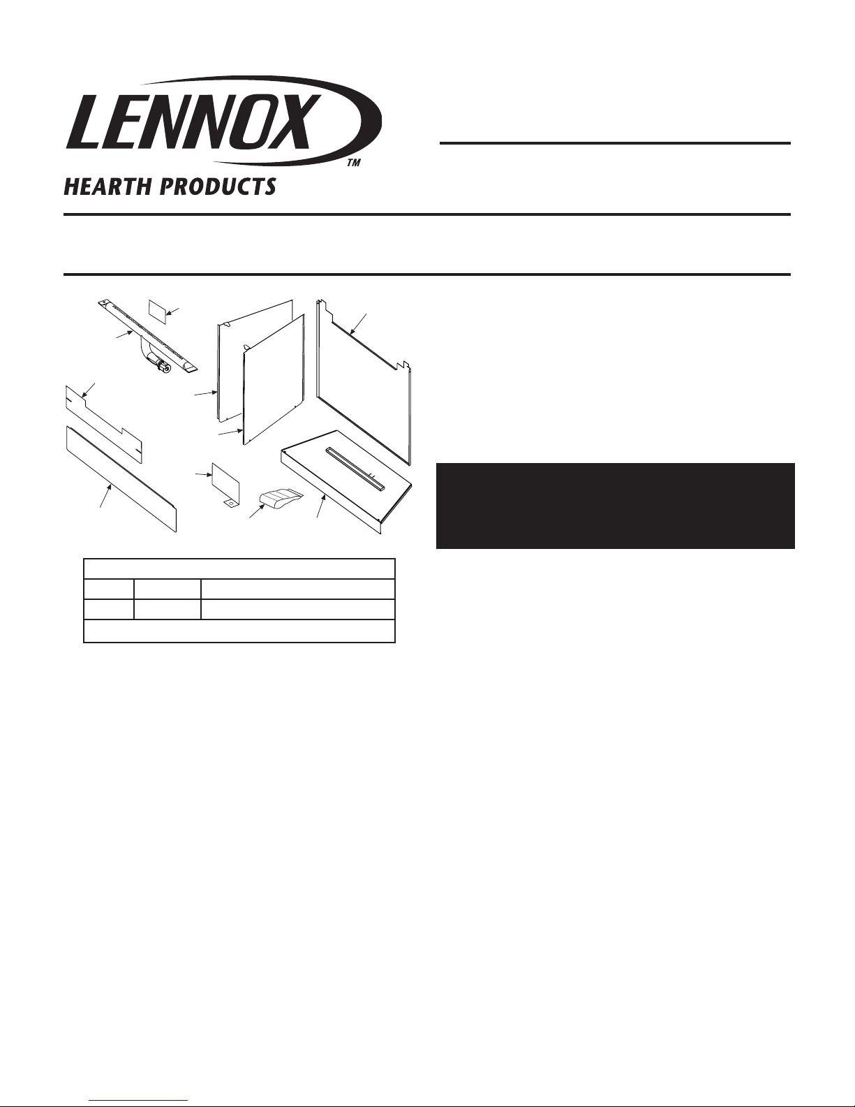
Attaching Parts
Burner
Assembly
Sub-Floor
Front Panel
Sub-Floor
Porcelain Panel
- Rear
Porcelain
Panel - Left
Porcelain
Panel - Right
Lower Baffle
Pilot
Shield
Label
KITS AND ACCESSORIES
INSTALLATION INSTRUCTIONS FOR THE MLDVTCD-35 CONVERSION KIT
FOR USE WITH MERIT™ SERIES MLDVT GAS FIREPLACES
MLDVTCD-35 Conversion Kit
Cat. No. Model No. Description
H7535 MCDK-35 35” Contemporary Conversion Kit
Table 1
506019-41
REV. N/C 04/2009
TURN OFF THE FIREPLACE AND ALLOW IT TO COMPLETELY COOL
BEFORE PROCEEDING.
CAUTION: TURN OF GAS TO THE APPLIANCE AND LOCK OUT ANY
ELECTRICAL SWITCHES.
IMPORTANT: Installation of this kit should be performed by a qualified service technician.
MLDVTCD-35
CONVERSION KIT
REMOVING THE GLASS DOOR
WARNING: Handle this glass with extreme care!
Tempered glass is susceptible to damage – do not
scratch or handle roughly while removing or installing the glass door.
1. To access the glass door securing latches, first open the lower control
compartment door by sliding and pulling the bottom panel forward.
2. Pull the latches forward and down to release them from the door
channel.
TOOLS REQUIRED
1 - Phillips Screwdriver, 1 - 5/16” Nut Driver
GENERAL INFORMATION
This MLDVTCD-35 Conversion Kit is used to convert an existing MLDVT
fireplace to a Contemporary MLDVTCD-35 fireplace. Please read this
instruction sheet in its entirety before beginning the installation.
The conversion kit consists of: One - Burner Assembly, One - Sub-Floor,
One - Sub-Floor Front Panel, One - Lower Baffle, One - Pilot Shield, One
- Porcelain Panel Kit (with Left, Right and Rear Porcelain Panels), One
- Bag of attaching parts, One Conversion Label and these instructions.
Refer to Table 1 for kit catalog and model numbers.
ALL WARNINGS AND PRECAUTIONS IN THE INSTALLATION AND
OPERATION MANUAL PROVIDED WITH THE APPLIANCE APPLY TO
THESE INSTRUCTIONS.
Refer to the appliance Care And Operations manual (P/N 506017-01) for
detailed instructions.
NOTE: DIAGRAMS & ILLUSTRATIONS NOT TO SCALE.
3. Pull the bottom of the door out a few inches and grasp it on the right
and left. Gently lift to release the door from its channel above the door.
Pull the door forward.
INSTALLING THE CONVERSION KIT
Removing The Existing Components (refer to Figure 1 on page 2).
Step 1. Locate the two screws securing the grate (refer to Figure 1 ).
Remove and retain the two screws holding the grate in place. The grate
may be discarded.
Step 2. Locate the two screws retaining the sub-floor in its location
between the burner front edge and the sub-floor (refer to Figure 1 ).
Remove and retain the additional screws and remove the sub-floor. The
sub-floor may be discarded. Re-install the screws.
Step 3. Remove the screw (refer to Figure 1 ) and remove the burner.
The burner may be discarded
Note: Take care when disengaging the burner from the venturi adjustment rod.
1
Page 2
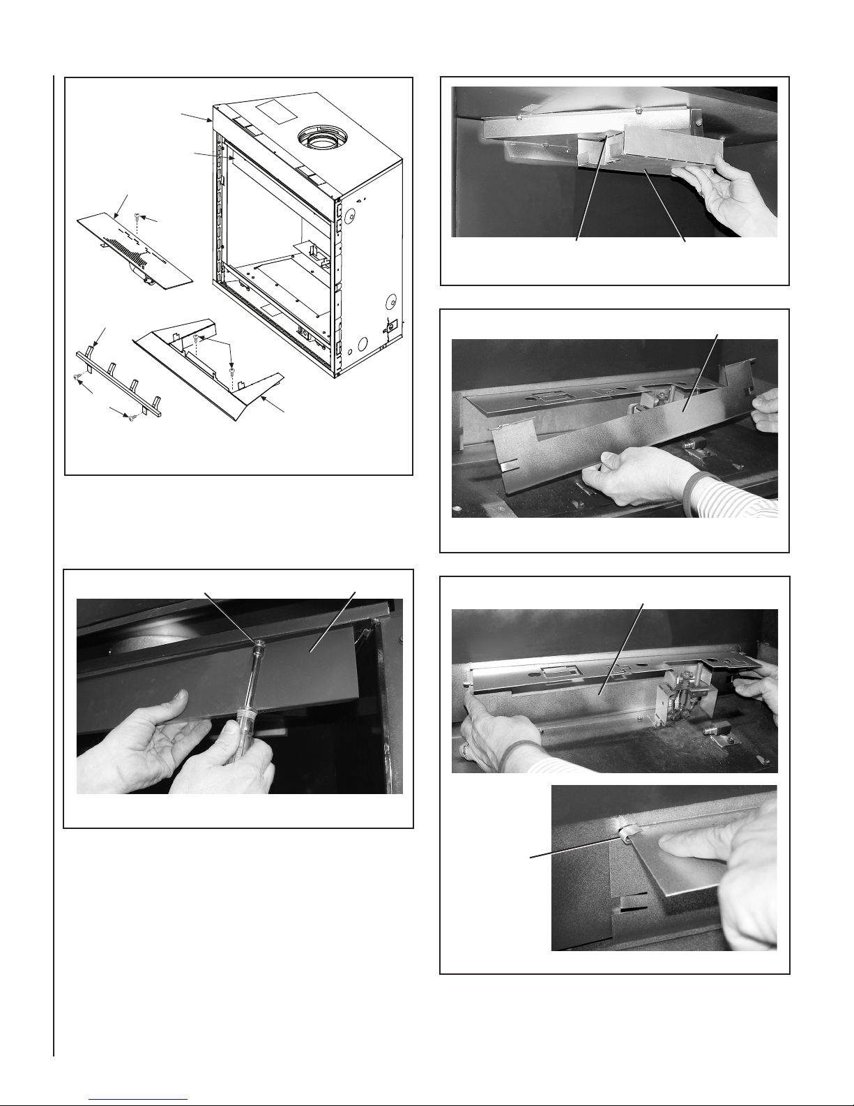
Figure 1 - Existing MLDVT Components
Burner Assembly
Sub-Floor
Grate
Firebox
Step 3
Step 2
Step 1
Lintel
Installing The Kit Components
Figure 3
Screw (2 Places)
Upper Baffle
Lower Baffle
Step 4. Remove (using a 5/16” nut driver) the lintel retaining screws
and then remove the lintel. See Figure 2.
Figure 2
Step 5. Remove the two screws attaching the upper baffle and then
remove the baffle (see Figure 3 ). The baffle may be discarded. Reinstall the screws.
Step 6. Position the lower baffle in place in the lower part of the firebox
(see Figure 4 ).
Lintel Attaching Screw (2 Places)
Lintel
Figure 4
Positioning The Lower Baffle
Left Wing Tab
Bent Into Place
Close the air entity portal by installing the lower baffle. First, insert the
tab on the left, then slide the baffle to the left in order to insert the right
tab. Then rest the lower baffle into place. Secure the baffle in place by
bending over the wing tabs (see Figure 5 ).
2
Figure 5
NOTE: DIAGRAMS & ILLUSTRATIONS NOT TO SCALE.
Page 3

Step 7. Install the Pilot Shield. Locate the screw shown in Figure 6.
Remove the screw. Place the pilot shield as shown and reinstall the
screw.
Step 9. Bend flat the log placement tabs on the existing log placement
bracket (see Figure 8 ).
Bend Down Existing Log Placement Tabs
Figure 8
Pilot Shield
Attaching Screw
(2 Places)
Pilot Shield
Figure 6
Step 8. Install the Burner. Locate the burner adjustment rod and secure
the burner in place, as shown in Figure 7.
Burner
Adjustment Rod
Step 10. Install the new sub-floor over the existing log placement bracket
(see Figure 9 ). Ensure the tabs on the bottom front edge of the subfloor are placed behind the front lip of the lower firebox.
Placing The New Sub-Floor
Figure 9
Step 11. Install the Porcelain Panels (refer to Figure 10 ).
Position the rear panel in place against the firebox back wall. Place the
side panels in position by sliding them into the groves at the outer edges
of the sub-floor (holes in the side panels down). The side panels lock
the rear panel in place by capturing the rear panel alignment flanges
(right and left) between them.
Note: Bend the tabs (shown in Figure 11 ) at the front top corner of
the side porcelain panels before installing them.
Burner
Bracket
Figure 7
Step 12. Bend up the tab on the top front of the side panels (refer to
Figure 11 ), so that they are behind the lintel when it is re-installed.
Step 13. Reinstall the lintel (refer to Figure 2 ).
NOTE: DIAGRAMS & ILLUSTRATIONS NOT TO SCALE.
3
Page 4

Groove In Edge Of Sub-Floor
Rear Panel Alignment Flange
Step 14. If loose floor media, such as sand or crushed glass is to be
used, install the sub-floor front panel (see Figure 12 ).
Hole At Bottom Of Side Panel
Side Panel In Place
Figure 10
Rear Panel
Alignment Flange Behind
Side Panel - Top Front Tab
Sub-Floor Front Panel
Figure 12
Re-Installing The Glass Door
1. Retrieve the glass door. Visually inspect the gasket on the backside
of the frame. Gasket surface must be clean, free of irregularities and
seated firmly.
2. Position the door in front of the firebox opening with the bottom of
the door held away from the fireplace. Hook the top flange of the door
frame over the top of the firebox frame.
3. Let the bottom of the door frame swing gently in towards the fireplace
ensuring that the gasket seats evenly as the door frame draws shut.
Fasten the two latches located underneath the firebox floor to the door's
vee-flange. Close both the latches securely.
4. Turn on the gas. Restore electrical power.
Figure 11
Lennox Hearth Products reserves the right to make changes at any time, without notice, in design, materials, specifications, prices and also to discontinue colors, styles and products.
Consult your local distributor for fireplace code information.
Printed in U.S.A. © 2009 by LENNOX HEARTH PRODUCTS
P/N 506019-41 REV. N/C 04/2009
4
NOTE: DIAGRAMS & ILLUSTRATIONS NOT TO SCALE.
NOTE: DIAGRAMS & ILLUSTRATIONS NOT TO SCALE.
LHP
1110 West Taft Avenue • Orange, CA 92865
 Loading...