

Page 1
Corp. 1903-L1
Service Literature
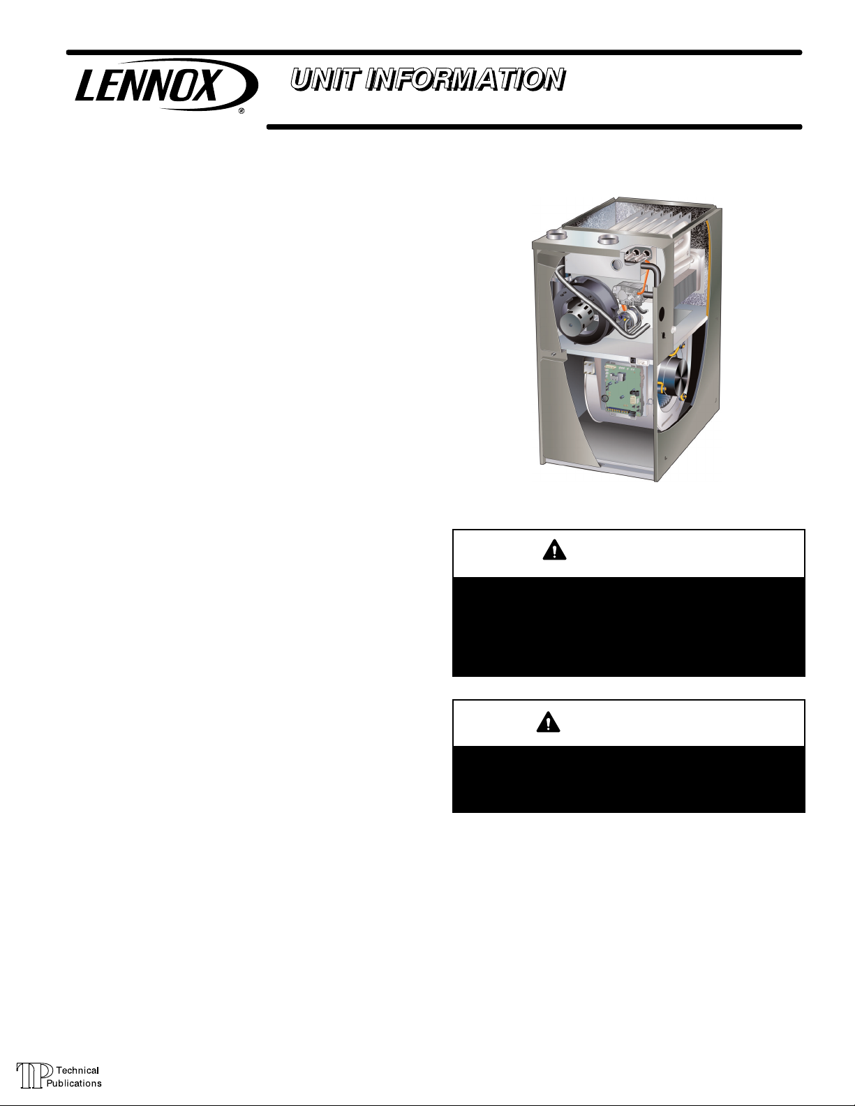
ML296UHV(X) SERIES UNITS
ML296UHV(X) series units are 90% efficiency gas fur
naces used for upflow or horizontal applications only,
manufactured with Lennox Duralokt heat exchangers
formed of aluminized steel. ML296UHV(X) units are avail
able in heating capacities of 44,000 to 132,000 Btuh and
cooling applications up to 5 tons. Refer to Engineering
Handbook for proper sizing.
Units are factory equipped for use with natural gas. Kits are
available for conversion to LPG operation. ML296UHV(X)
unit meets the California Nitrogen Oxides (NO
and California Seasonal Efficiency requirements. All units
use a redundant gas valve to assure safety shut-off as re
quired by C.S.A.
All specifications in this manual are subject to change. Pro
cedures outlined in this manual are presented as a recom
mendation only and do not supersede or replace local or
state codes. In the absence of local or state codes, the
guidelines and procedures outlined in this manual (except
where noted) are recommendations only and do not consti
tute code.
TABLE OF CONTENTS
Specifications Page 2.............................
Blower Data Page 3..............................
I Unit Components Page 9........................
II Installation Page 21.............................
III Start Up Page 43..............................
IV Heating System Service Checks Page 44.........
V Typical Operating Characteristics Page 47.........
VI Maintenance Page 47..........................
VII Wiring and Sequence of Operation Page 50......
) Standards
x
ML296UHV(X)
WARNING
Improper installation, adjustment, alteration, service
or maintenance can cause property damage, person
al injury or loss of life. Installation and service must
be performed by a licensed professional HVAC in
staller (or equivalent), service agency or the gas sup
plier.
CAUTION
As with any mechanical equipment, contact with
sharp sheet metal edges can result in personal in
jury. Take care while handling this equipment and
wear gloves and protective clothing.
Page 1
© 2019 Lennox Industries Inc.
Page 2

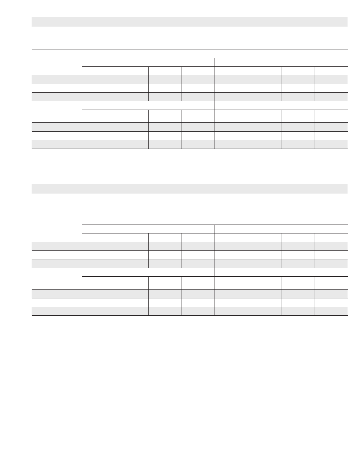
SPECIFICATIONS
Gas
Heating
AHRI Reference No. N/A N/A
Performance
High
Fire
Temperature rise range - °F 35 - 65 50 - 80
Gas Manifold Pressure (in. w.g.)
Nat. Gas / LPG/Propane
Low
Fire
Temperature rise range - °F 20 - 50 25 - 55
Gas Manifold Pressure (in. w.g.)
Nat. Gas / LPG/Propane
High static - in. w.g. Heating 0.8 0.8
Connections
Intake / Exhaust Pipe (PVC) 2 / 2 2 / 2
in.
Condensate Drain Trap (PVC pipe) - i.d. 3/4 3/4
with furnished 90° street elbow 3/4 slip x 3/4 Mipt 3/4 slip x 3/4 Mipt
with eld supplied (PVC coupling) - o.d. 3/4 slip x 3/4 MPT 3/4 slip x 3/4 MPT
Indoor
Wheel nominal diameter x width - in. 10 x 9 10 x 9
Blower
Tons of add-on cooling 2 - 3 2 - 3
Air Volume Range - cfm 485 - 1370 500 - 1365
Electrical Data Voltage 120 volts - 60 hertz - 1 phase
Blower motor full load amps 7.7 7.7
Maximum overcurrent protection 15 15
Shipping Data lbs. - 1 package 130 138
NOTE - Filters and provisions for mounting are not furnished and must be eld provided.
1
Annual Fuel Utilization Eciency based on DOE test procedures and according to FTC labeling regulations. Isolated combustion system rating for non-weatherized furnaces.
Model No. ML296UH045XV36B ML296UH070XV36B
1
AFUE 96% 96%
Input - Btuh 44,000 66,000
Output - Btuh 42,000 62,000
3.5 / 10.0 3.5 / 10.0
Input - Btuh 29,000 43,000
Output - Btuh 28,000 41,000
1.7 / 4.9 1.7 / 4.9
Cooling 1.0 1.0
Gas pipe size IPS 1/2 1/2
Motor output - hp 1/2 1/2
Gas
Heating
Performance
AHRI Reference No. N/A N/A
High
Fire
Model No. ML296UH090XV48C ML296UH110XV60C
1
AFUE 96% 96%
Input - Btuh 88,000 110,000
Output - Btuh 84,000 106,000
Temperature rise range - °F 45 - 75 45 - 75
Gas Manifold Pressure (in. w.g.)
3.5 / 10.0 3.5 / 10.0
Nat. Gas / LPG/Propane
Low
Fire
Input - Btuh 57,000 72,000
Output - Btuh 55,000 70,000
Temperature rise range - °F 30 - 60 35 - 65
Gas Manifold Pressure (in. w.g.)
1.7 / 4.9 1.7 / 4.9
Nat. Gas / LPG/Propane
High static - in. w.g. Heating 0.8 0.8
Cooling 1.0 1.0
Connections
in.
Intake / Exhaust Pipe (PVC) 2 / 2 2 / 2
Gas pipe size IPS 1/2 1/2
Condensate Drain Trap (PVC pipe) - i.d. 3/4 3/4
with furnished 90° street elbow 3/4 slip x 3/4 Mipt
3/4 slip x 3/4 Mipt
with eld supplied (PVC coupling) - o.d. 3/4 slip x 3/4 MPT 3/4 slip x 3/4 MPT
Indoor
Blower
Wheel nominal diameter x width - in. 11 x 11 11 x 11
Motor output - hp 3/4 1
Tons of add-on cooling 2.5 - 4 3 - 5
Air Volume Range - cfm 680 - 1770 790 - 1955
Electrical Data Voltage 120 volts - 60 hertz - 1 phase
Blower motor full load amps 10.1 12.8
Maximum overcurrent protection 15 20
Shipping Data lbs. - 1 package 163 174
NOTE - Filters and provisions for mounting are not furnished and must be eld provided.
1
Annual Fuel Utilization Eciency based on DOE test procedures and according to FTC labeling regulations. Isolated combustion system rating for non-weatherized furnaces.
Page 2
Page 3
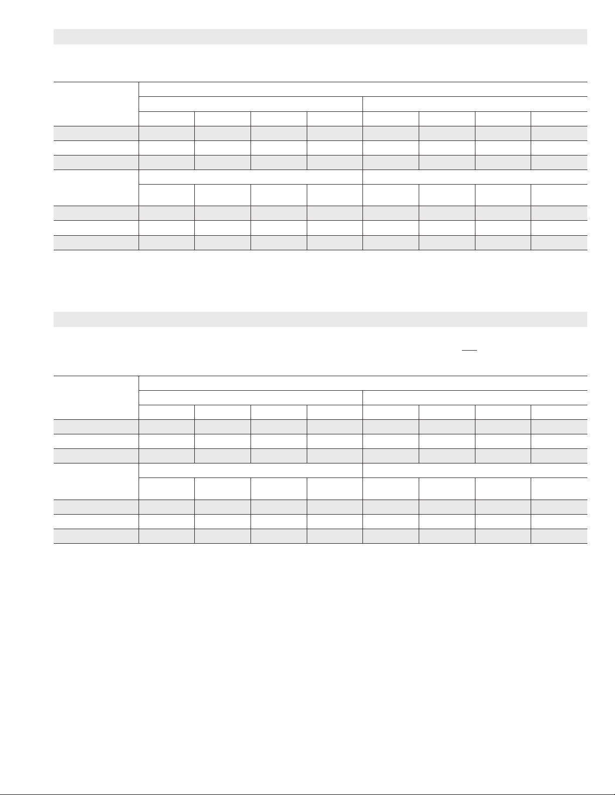
BLOWER DATA
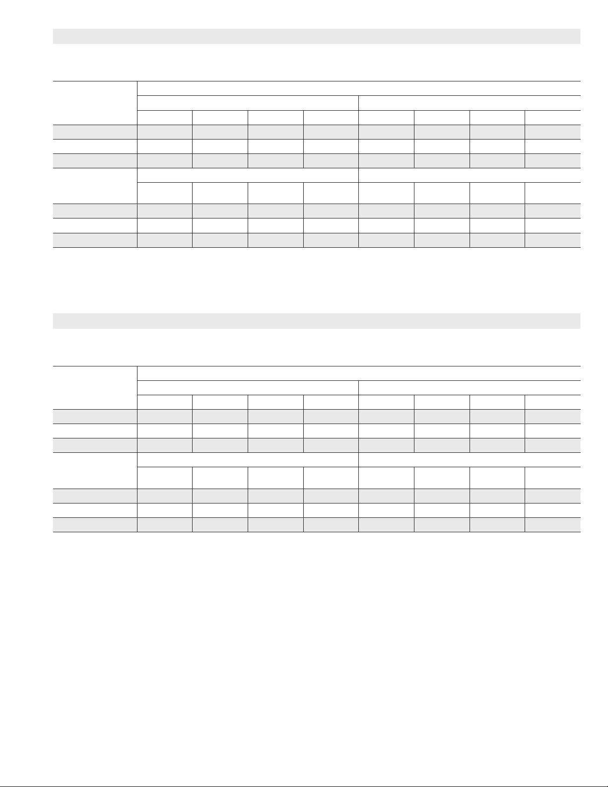
ML296UH045XV36B BLOWER PERFORMANCE (less lter)
BOTTOM RETURN AIR
0 through 0.8 in. w.g. (Heating) and 0 through 1.0 in. w.g. (Cooling) External Static Pressure Range
“ADJUST”
Switch
Positions
Second Stage “HEAT” Speed - cfm Second Stage “COOL” Speed - cfm
1
D
C B A D C B
+ 745 875 990 1005 905 1075 1210 1370
1
NORM 685 765 895 910 815 980 1120 1255
— 610 695 785 810 720 885 1020 1135
“ADJUST”
Switch
Positions
First Stage “HEAT” Speed - cfm First Stage “COOL” Speed - cfm
D
1
C B A D C B
+ 685 765 895 910 595 760 865 980
1
NORM 620 705 800 820 540 660 785 890
— 545 625 715 725 485 600 695 790
1
Factory default jumper setting.
NOTES - The eect of static pressure is included in air volumes shown.
First stage HEAT is approximately 91% of the same second stage HEAT speed position.
First stage COOL (two-stage air conditioning units only) is approximately 70% of the same second stage COOL speed
position. Continuous Fan Only speed is approximately 38% of the same second stage COOL speed position - minimum
500 cfm. Lennox Harmony III™ Zoning System Applications - Minimum blower speed is 453 cfm.
BLOWER DATA
ML296UH045XV36B BLOWER PERFORMANCE (less lter)
SINGLE SIDE RETURN AIR
0 through 0.8 in. w.g. (Heating) and 0 through 1.0 in. w.g. (Cooling) External Static Pressure Range
“ADJUST”
Switch
Positions
+ 780 880 990 1010 920 1065 1205 1340
1
NORM 705 795 905 925 815 985 111 0 1245
— 640 715 805 810 745 890 1020 1130
“ADJUST”
Switch
Positions
+ 705 795 905 925 610 760 845 975
1
NORM 645 725 810 815 550 680 770 880
— 570 655 735 750 465 610 720 775
1
Factory default jumper setting.
NOTES - The eect of static pressure is included in air volumes shown.
First stage HEAT is approximately 91% of the same second stage HEAT speed position.
First stage COOL (two-stage air conditioning units only) is approximately 70% of the same second stage COOL speed
position. Continuous Fan Only speed is approximately 38% of the same second stage COOL speed position - minimum
500 cfm. Lennox Harmony III™ Zoning System Applications - Minimum blower speed is 453 cfm.
Second Stage “HEAT” Speed - cfm Second Stage “COOL” Speed - cfm
1
D
C B A D C B
First Stage “HEAT” Speed - cfm First Stage “COOL” Speed - cfm
D
1
C B A D C B
Speed Switch Positions
Speed Switch Positions
1
A
1
A
1
A
1
A
Page 3
Page 4
BLOWER DATA
ML296UH045XV36B BLOWER PERFORMANCE (less lter)
SINGLE SIDE RETURN AIR
0 through 0.8 in. w.g. (Heating) and 0 through 1.0 in. w.g. (Cooling) External Static Pressure Range
“ADJUST”
Switch
Positions
Second Stage “HEAT” Speed - cfm Second Stage “COOL” Speed - cfm
1
D
C B A D C B
Speed Switch Positions
+ 780 880 990 1010 920 1065 1205 1340
1
NORM 705 795 905 925 815 985 111 0 1245
— 640 715 805 810 745 890 1020 1130
“ADJUST”
Switch
Positions
First Stage “HEAT” Speed - cfm First Stage “COOL” Speed - cfm
D
1
C B A D C B
+ 705 795 905 925 610 760 845 975
1
NORM 645 725 810 815 550 680 770 880
— 570 655 735 750 465 610 720 775
1
Factory default jumper setting.
NOTES - The eect of static pressure is included in air volumes shown.
First stage HEAT is approximately 91% of the same second stage HEAT speed position.
First stage COOL (two-stage air conditioning units only) is approximately 70% of the same second stage COOL speed
position. Continuous Fan Only speed is approximately 38% of the same second stage COOL speed position - minimum
500 cfm. Lennox Harmony III™ Zoning System Applications - Minimum blower speed is 453 cfm.
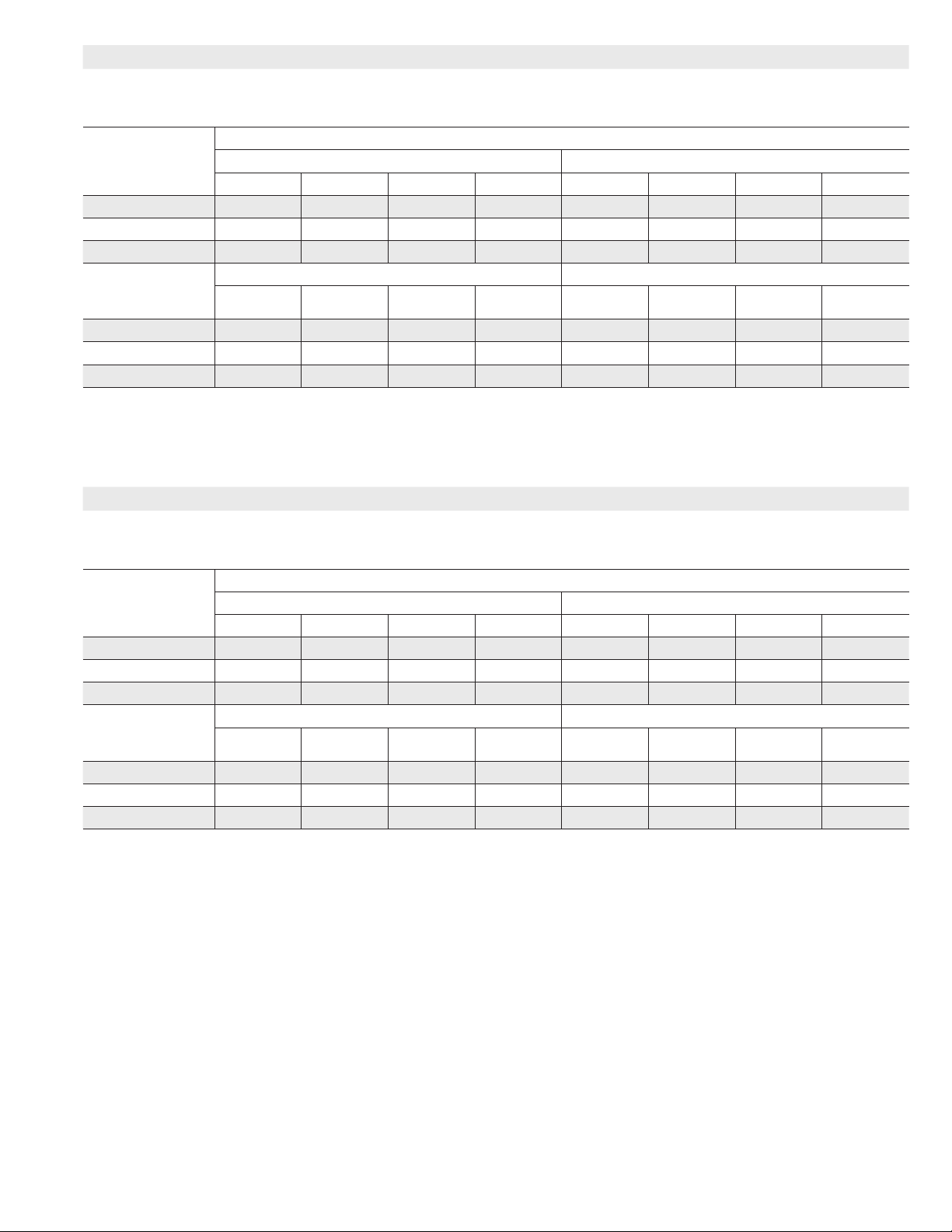
BLOWER DATA
ML296UH070XV36B BLOWER PERFORMANCE (less lter)
BOTTOM RETURN AIR
0 through 0.8 in. w.g. (Heating) and 0 through 1.0 in. w.g. (Cooling) External Static Pressure Range
“ADJUST”
Switch
Positions
Second Stage “HEAT” Speed - cfm Second Stage “COOL” Speed - cfm
1
D
C B A D C B
+ 965 1130 1255 1400 860 1060 1215 1365
1
NORM 880 990 1140 1295 810 960 1130 1265
— 810 890 1030 1170 705 840 1005 1140
“ADJUST”
Switch
Positions
First Stage “HEAT” Speed - cfm First Stage “COOL” Speed - cfm
D
1
C B A D C B
+ 940 1070 1195 1345 600 740 840 970
1
NORM 830 965 1100 1235 555 665 770 855
— 755 840 975 1130 500 600 680 790
1
Factory default jumper setting.
NOTES - The eect of static pressure is included in air volumes shown.
First stage HEAT is approximately 91% of the same second stage HEAT speed position.
First stage COOL (two-stage air conditioning units only) is approximately 70% of the same second stage COOL speed
position. Continuous Fan Only speed is approximately 38% of the same second stage COOL speed position - minimum
500 cfm. Lennox Harmony III™ Zoning System Applications - Minimum blower speed is 453 cfm.
Speed Switch Positions
1
A
1
A
1
A
1
A
Page 4
Page 5
BLOWER DATA
ML296UH070XV36B BLOWER PERFORMANCE (less lter)
SINGLE SIDE RETURN AIR
0 through 0.8 in. w.g. (Heating) and 0 through 1.0 in. w.g. (Cooling) External Static Pressure Range
“ADJUST”
Switch
Positions
Second Stage “HEAT” Speed - cfm Second Stage “COOL” Speed - cfm
1
D
C B A D C B
Speed Switch Positions
+ 980 1095 1225 1395 840 1050 1205 1355
1
NORM 855 1005 1120 1250 750 945 1130 1230
— 755 870 1020 1170 685 805 990 1110
“ADJUST”
Switch
Positions
First Stage “HEAT” Speed - cfm First Stage “COOL” Speed - cfm
D
1
C B A D C B
+ 920 1055 1205 1325 590 705 805 955
1
NORM 800 950 1075 1215 540 640 725 820
— 730 810 960 1095 500 580 665 720
1
Factory default jumper setting.
NOTES - The eect of static pressure is included in air volumes shown.
First stage HEAT is approximately 91% of the same second stage HEAT speed position.
First stage COOL (two-stage air conditioning units only) is approximately 70% of the same second stage COOL speed
position. Continuous Fan Only speed is approximately 38% of the same second stage COOL speed position - minimum
500 cfm. Lennox Harmony III™ Zoning System Applications - Minimum blower speed is 453 cfm.
BLOWER DATA
ML296UH070XV36B BLOWER PERFORMANCE (less lter)
SIDE RETURN AIR WITH OPTIONAL RETURN AIR BASE
0 through 0.8 in. w.g. (Heating) and 0 through 1.0 in. w.g. (Cooling) External Static Pressure Range
“ADJUST”
Switch
Positions
Second Stage “HEAT” Speed - cfm Second Stage “COOL” Speed - cfm
1
D
C B A D C B
+ 975 1095 1245 1385 855 1045 1205 1350
1
NORM 870 995 1130 1280 790 945 1090 1255
— 790 885 1010 1155 720 845 985 1130
“ADJUST”
Switch
Positions
First Stage “HEAT” Speed - cfm First Stage “COOL” Speed - cfm
D
1
C B A D C B
+ 925 1050 1175 1330 595 715 815 950
1
NORM 810 945 1070 1220 520 655 755 840
— 730 840 955 1095 490 595 670 745
1
Factory default jumper setting.
NOTES - The eect of static pressure is included in air volumes shown.
First stage HEAT is approximately 91% of the same second stage HEAT speed position.
First stage COOL (two-stage air conditioning units only) is approximately 70% of the same second stage COOL speed
position. Continuous Fan Only speed is approximately 38% of the same second stage COOL speed position - minimum
500 cfm. Lennox Harmony III™ Zoning System Applications - Minimum blower speed is 453 cfm.
Speed Switch Positions
1
A
1
A
1
A
1
A
Page 5
Page 6

BLOWER DATA
ML296UH090XV48C BLOWER PERFORMANCE (less lter)
BOTTOM RETURN AIR, RETURN AIR FROM BOTH SIDES OR RETURN AIR FROM BOTTOM AND ONE SIDE
0 through 0.8 in. w.g. (Heating) and 0 through 1.0 in. w.g. (Cooling) External Static Pressure Range
“ADJUST”
Switch
Positions
Second Stage “HEAT” Speed - cfm Second Stage “COOL” Speed - cfm
1
D
C B A D C B
+ 1230 1310 1360 1605 1165 1375 1580 1770
1
NORM 1115 1195 1255 1455 1075 1265 1440 1645
— 1005 1070 1130 1335 935 1145 1320 1465
“ADJUST”
Switch
Positions
First Stage “HEAT” Speed - cfm First Stage “COOL” Speed - cfm
D
1
C B A D C B
+ 1165 1250 1315 1520 840 1005 1155 1315
1
NORM 1075 1140 1195 1405 780 915 1045 1190
— 935 1030 1065 1285 690 835 955 1070
1
Factory default jumper setting.
NOTES - The eect of static pressure is included in air volumes shown.
First stage HEAT is approximately 91% of the same second stage HEAT speed position.
First stage COOL (two-stage air conditioning units only) is approximately 70% of the same second stage COOL speed
position. Continuous Fan Only speed is approximately 38% of the same second stage COOL speed position - minimum
500 cfm. Lennox Harmony III™ Zoning System Applications - Minimum blower speed is 453 cfm.
Speed Switch Positions
1
A
1
A
BLOWER DATA
ML296UH090XV48C BLOWER PERFORMANCE (less lter)
SINGLE SIDE RETURN AIR
0 through 0.8 in. w.g. (Heating) and 0 through 1.0 in. w.g. (Cooling) External Static Pressure Range
“ADJUST”
Switch
Positions
Second Stage “HEAT” Speed - cfm Second Stage “COOL” Speed - cfm
1
D
C B A D C B
+ 1210 1275 1320 1555 1140 1340 1525 1725
1
NORM 1115 1175 1230 1400 1040 1235 1395 1565
— 990 1070 1125 1295 910 1120 1275 1400
“ADJUST”
Switch
Positions
First Stage “HEAT” Speed - cfm First Stage “COOL” Speed - cfm
D
1
C B A D C B
+ 1140 1230 1280 1455 820 1005 1135 1290
1
NORM 1040 1135 1180 1370 755 880 1025 1150
— 910 1000 1075 1250 680 815 925 1065
1
Factory default jumper setting.
NOTES - The eect of static pressure is included in air volumes shown.
First stage HEAT is approximately 91% of the same second stage HEAT speed position.
First stage COOL (two-stage air conditioning units only) is approximately 70% of the same second stage COOL speed
position. Continuous Fan Only speed is approximately 38% of the same second stage COOL speed position - minimum
500 cfm. Lennox Harmony III™ Zoning System Applications - Minimum blower speed is 453 cfm.
Speed Switch Positions
1
A
1
A
Page 6
Page 7
BLOWER DATA
ML296UH110XV60C BLOWER PERFORMANCE (less lter)
BOTTOM RETURN AIR, RETURN AIR FROM BOTH SIDES OR RETURN AIR FROM BOTTOM AND ONE SIDE
0 through 0.8 in. w.g. (Heating) and 0 through 1.0 in. w.g. (Cooling) External Static Pressure Range
“ADJUST”
Switch
Positions
Second Stage “HEAT” Speed - cfm Second Stage “COOL” Speed - cfm
1
D
C B A D C B
Speed Switch Positions
1
A
+ 1560 1760 1905 2080 1312 1560 1744 1955
1
NORM 1415 1610 1740 1930 1219 1405 1569 1796
— 1285 1485 1560 1745 1075 1272 1428 1634
“ADJUST”
Switch
Positions
First Stage “HEAT” Speed - cfm First Stage “COOL” Speed - cfm
D
1
C B A D C B
1
A
+ 1155 1325 1420 1565 937 1064 1247 1407
1
NORM 1055 1200 1310 1480 864 972 1146 1282
— 935 1075 1170 1315 790 888 1025 1167
1
Factory default jumper setting.
NOTES - The eect of static pressure is included in air volumes shown.
First stage HEAT is approximately 91% of the same second stage HEAT speed position.
First stage COOL (two-stage air conditioning units only) is approximately 70% of the same second stage COOL speed
position. Continuous Fan Only speed is approximately 38% of the same second stage COOL speed position - minimum
500 cfm. Lennox Harmony III™ Zoning System Applications - Minimum blower speed is 478 cfm.
BLOWER DATA
ML296UH110XV60C BLOWER PERFORMANCE (less lter)
SINGLE SIDE RETURN AIR − Air volumes in bold (over 1800 cfm) require Optional Return Air Base and eld fabricated transition
to accommodate 20 x 25 x 1 in. air lter in order to maintain proper air velocity.
0 through 0.8 in. w.g. (Heating) and 0 through 1.0 in. w.g. (Cooling) External Static Pressure Range
“ADJUST”
Switch
Positions
Second Stage “HEAT” Speed - cfm Second Stage “COOL” Speed - cfm
1
D
C B A D C B
+ 1530 1735 1845 2025 1270 1519 1712 1899
1
NORM 1380 1555 1705 1860 1170 1363 1555 1774
— 1235 1440 1540 1710 1059 1218 1401 1581
“ADJUST”
Switch
Positions
First Stage “HEAT” Speed - cfm First Stage “COOL” Speed - cfm
D
1
C B A D C B
+ 1140 1280 1390 1550 918 1053 1198 1366
1
NORM 1040 1175 1260 1430 820 964 1095 1231
— 910 1080 1150 1265 722 852 987 1116
1
Factory default jumper setting.
NOTES - The eect of static pressure is included in air volumes shown.
First stage HEAT is approximately 91% of the same second stage HEAT speed position.
First stage COOL (two-stage air conditioning units only) is approximately 70% of the same second stage COOL speed
position. Continuous Fan Only speed is approximately 38% of the same second stage COOL speed position - minimum
500 cfm. Lennox Harmony III™ Zoning System Applications - Minimum blower speed is 478 cfm.
Speed Switch Positions
1
A
1
A
Page 7
Page 8
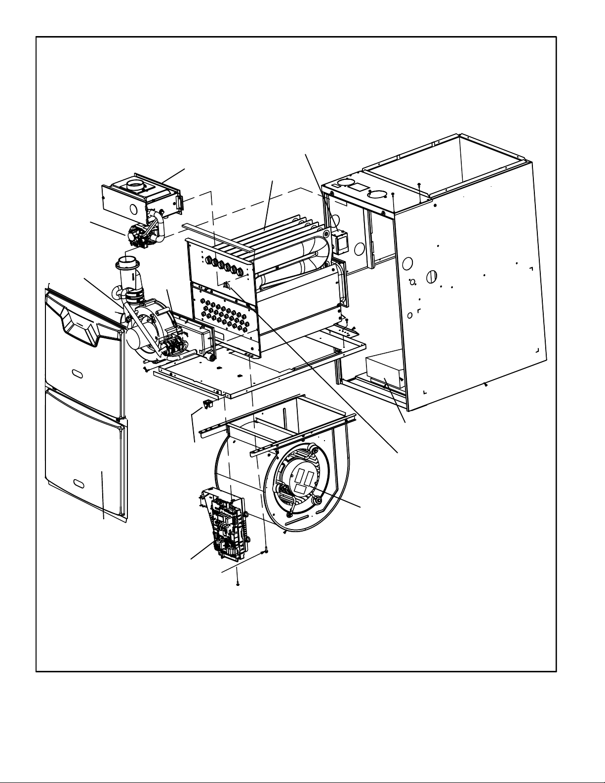
Gas Valve
ML296UHV PARTS IDENTIFICATION
Field Make Up Box
Burner Box Assembly
Heat Exchanger
Combustion
Air Inducer
Access Panel
Pressure
Switch
Assembly
Door
Interlock
Switch
Bag Assemblies
(shipping location)
Primary Limit
Variable Speed Motor
Two-Stage Integrated Control
FIGURE 1
Page 8
Page 9
I-UNIT COMPONENTS
ML296UHV(X) unit components are shown in figure 1. The
gas valve, combustion air inducer and burners can be ac
cessed by removing the access panel. Electrical compo
nents are in the control box (figure 2) found in the blower
section.
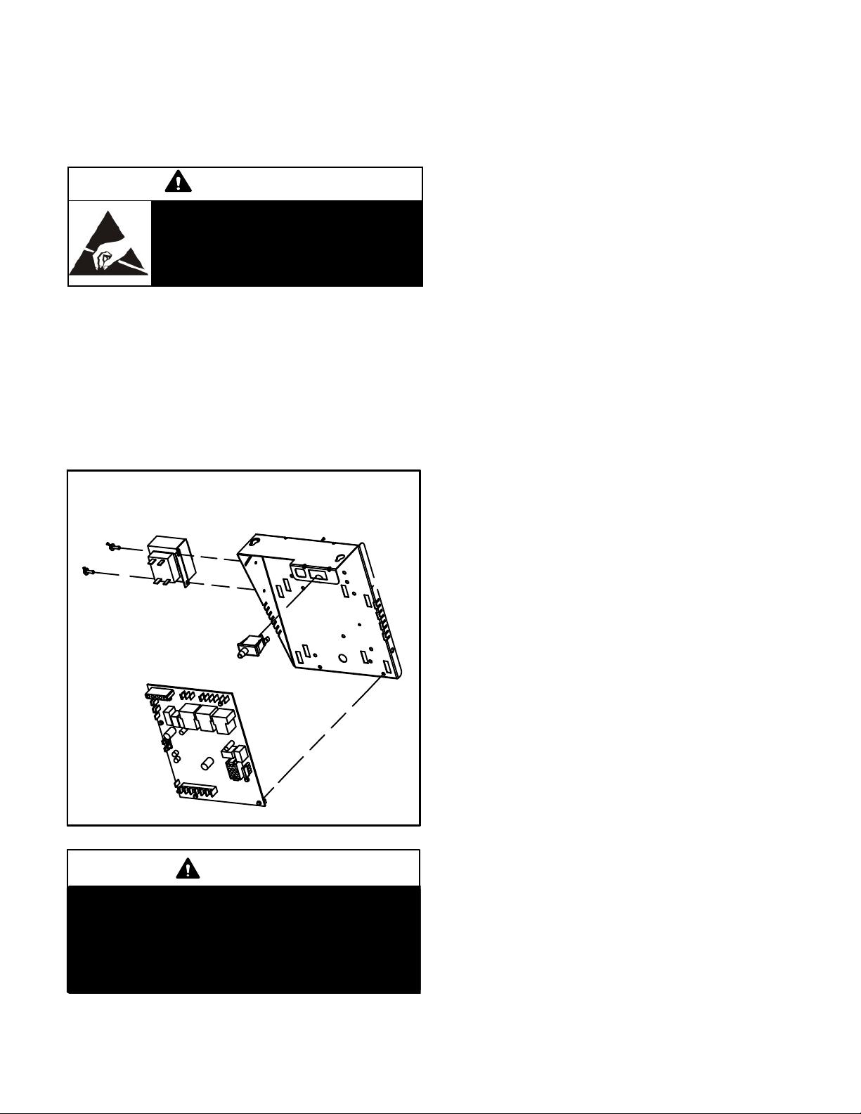
CAUTION
Electrostatic discharge can affect elec
tronic components. Take precautions
to neutralize electrostatic charge by
touching your hand and tools to metal
prior to handling the control.
A- Control Box
1. Control Transformer (T1)
A transformer located in the control box provides power to
the low voltage section of the unit. Transformers on all
models are rated 40VA with a 120V primary and a 24V sec
ondary.
2. Door Interlock Switch (S51)
A door interlock switch rated 14A at 125VAC is wired in se
ries with line voltage. When the inner blower access panel
is removed the unit will shut down.
Control Box Components
Transformer
3. Integrated Control (A92)
Units are equipped with a two-stage, variable speed inte
grated control. The system consists of a ignition / blower
control (figure 3) with control pin designations in tables 3
and 4 and ignitor. The control and ignitor work in combina
tion to ensure furnace ignition and ignitor durability. The
control provides gas ignition, safety checks and indoor
blower control with two-stage gas heating. The furnace
combustion air inducer, gas valve and indoor blower are
controlled in response to various system inputs such as
thermostat signal, pressure and limit switch signal and
flame signal.
The furnace has a built-in, self-diagnostic capability. If a
system problem occurs, a fault code is shown by a red LED
on the control. The control continuously monitors its own
operation and the operation of the system. If a failure oc
curs, the LED will indicate the failure code. The flash codes
are presented in table 2.
Fault Code History Button
The control stores the last five fault codes in memory. A
pushbutton switch is located on the control. When the
pushbutton switch is pressed and released, the control
flashes the stored fault codes. The most recent fault code is
flashed first; the oldest fault code is flashed last. To clear
the fault code history, press and hold the pushbutton switch
in for more than 5 seconds before releasing.
Door Interlock Switch
Integrated Control
FIGURE 2
WARNING
Shock hazard.
Disconnect power before servicing. Integrated
control is not field repairable. If control is inoper
able, simply replace entire control.
Can cause injury or death. Unsafe operation will re
sult if repair is attempted.
Single Stage Thermostat Operation
The automatic heat staging option allows a single stage
thermostat to be used with two stage furnace models. To
activate this option, move the jumper pin (see Figure 3) to
desired setting (5 minutes or 10 minutes). The furnace will
start on 1st stage heat and stay at 1st stage heat for the
duration of the selected time before switching to 2nd stage
heat.
W1 on the integrated control must be connected to W1 on
the thermostat.
High Heat State LED
A green LED is provided on the control board to indicate
high heat state
(see Table 1).
CFM LED
An amber LED is provided on the control board to display
CFM. To determine what CFM the motor is delivering at any
time, count the number of times the amber LED flashes.
Each flash signifies 100 CFM; count the flashes and multi
ply by 100 to determine the actual CFM delivered (for ex
ample: 5 flashes x 100 = 500 CFM).
Page 9
Page 10
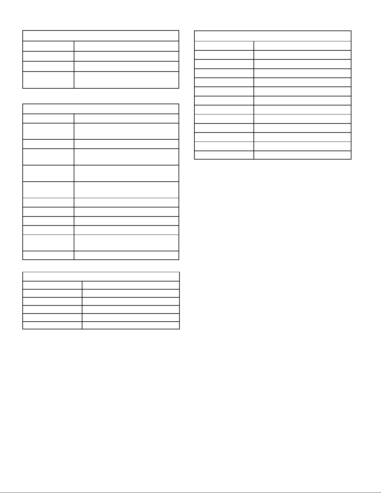
TABLE 1
High Heat State Green LED
LED Status DESCRIPTION
LED Off No demand for high heat
LED On High heat demand, operating normally
LED Flashing
High heat demand, high pressure
switch not closed
TABLE 2
Diagnostic Codes Red LED
LED Status DESCRIPTION
LED Off
LED On Normal operation.
1 Flash
2 Flashes
3 Flashes
4 Flashes Primary limit switch open.
5 Flashes Not used
6 Flashes Pressure switch cycle lockout.
7 Flashes Lockout, burners fail to light.
8 Flashes
9 Flashes Line voltage polarity incorrect.
Control 5 Pin Terminal Designation
PIN # Function
1 Ignitor (Hot)
2 Combustion Air Inducer High Speed
3 Combustion Air Inducer Low Speed
4 Combustion Air Inducer Neutral
5 Ignitor Neutral
Airflow Adjustments
Cooling Mode
The units are factory set for the highest airflow for each model.
Adjustments can be made to the cooling airflow by reposi
tioning the jumper plug marked COOL – A, B, C, D (see Fig
ure 3). To determine what CFM the motor is delivering at
any time, count the number of times the amber LED on the
control board flashes. Each flash signifies 100 CFM; count
the flashes and multiply by 100 to determine the actual CFM
delivered (for example: 5 flashes x 100 = 500 CFM).
No power to control or control harware
fault detected.
Flame present with gas vavle
de-energized.
Pressure switch closed with combustion
air inducer de-energized.
Low-fire pressure, rollout or limit
switch open.
Lockout, buners lost flame too many
times.
TABLE 3
TABLE 4
12 Pin Terminal Designation
PIN # Function
1 Gas Valve Second Stage
2 Second Stage Prove Switch
3 Rollout Switch In
4 Ground
5 24V Hot
6 Primary Limit In
7 Gas Valve First Stage
8 Gas Valve Common
9 24V Neutral
10 Ground
11 Rollout Switch Out
12 First Stage Prove Switch
Heating Mode
These units are factory set to run at the middle of the heating
rise range as shown on the unit rating plate. If higher or lower
rise is desired, reposition the jumper plug marked HEAT - A,
B, C, C (see Figure 3) . To determine what CFM the motor is
delivering at any time, count the number of times the amber
LED on the control board flashes. Each flash signifies 100
CFM; count the flashes and multiply by 100 to determine the
actual CFM delivered (for example: 5 flashes x 100= 500.
Adjust Tap
Airflow amounts may be increased or decreased by 10% by
moving the ADJUST jumper plug (see Figure 3) from the
NORM position to the (+) or (-) position. Changes to the AD
JUST tap will affect both cooling and heating airflows. The
TEST position on the ADJUST tap is not used.
Continuous Blower Operation
The comfort level of the living space can be enhanced
when using this feature by allowing continuous circulation
of air between calls for cooling or heating. The circulation of
air occurs at half the full cooling airflow rate.
To engage the continuous blower operation, place the fan
switch on the thermostat into the ON position. A call for fan
from the thermostat closes R to G on the ignition control
board. The control waits for a 1 second thermostat delay
before responding to the call for fan by ramping the circulat
ing blower up to 50% of the cooling speed. When the call for
continuous fan is satisfied, the control immediately ramps
down the circulating blower.
Page 10
Page 11
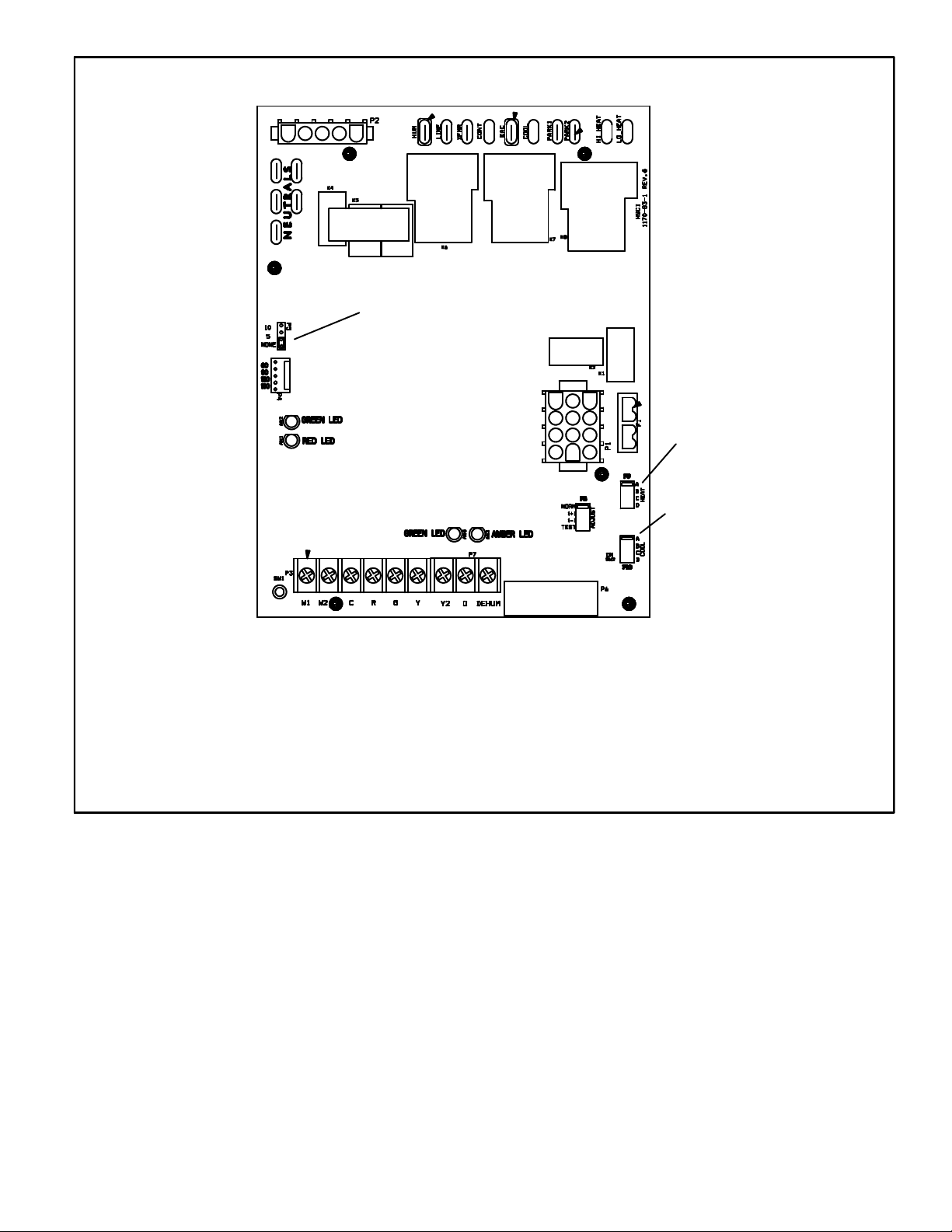
INTEGRATED CONTROL
Heat Stage Jumper
(single stage shown)
Air Flow
Jumper
TERMINAL DESIGNATIONS
HUM -Humidifier (120VAC)
Line - Input (120VAC)
XFMR - Transformer (120VAC)
Cont - Continuous blower
EAC - Indoor Air Accessory (120VAC)
Cool - Cool Speed (120VAC)
Park 1 - Dead terminal for alternate speed tap
Park 2 - Dead terminal for alternate speed tap
HI Heat - High heat speed
LO Heat - Low heat speed
FIGURE 3
Heat
Taps
Cool
Taps
Page 11
Page 12
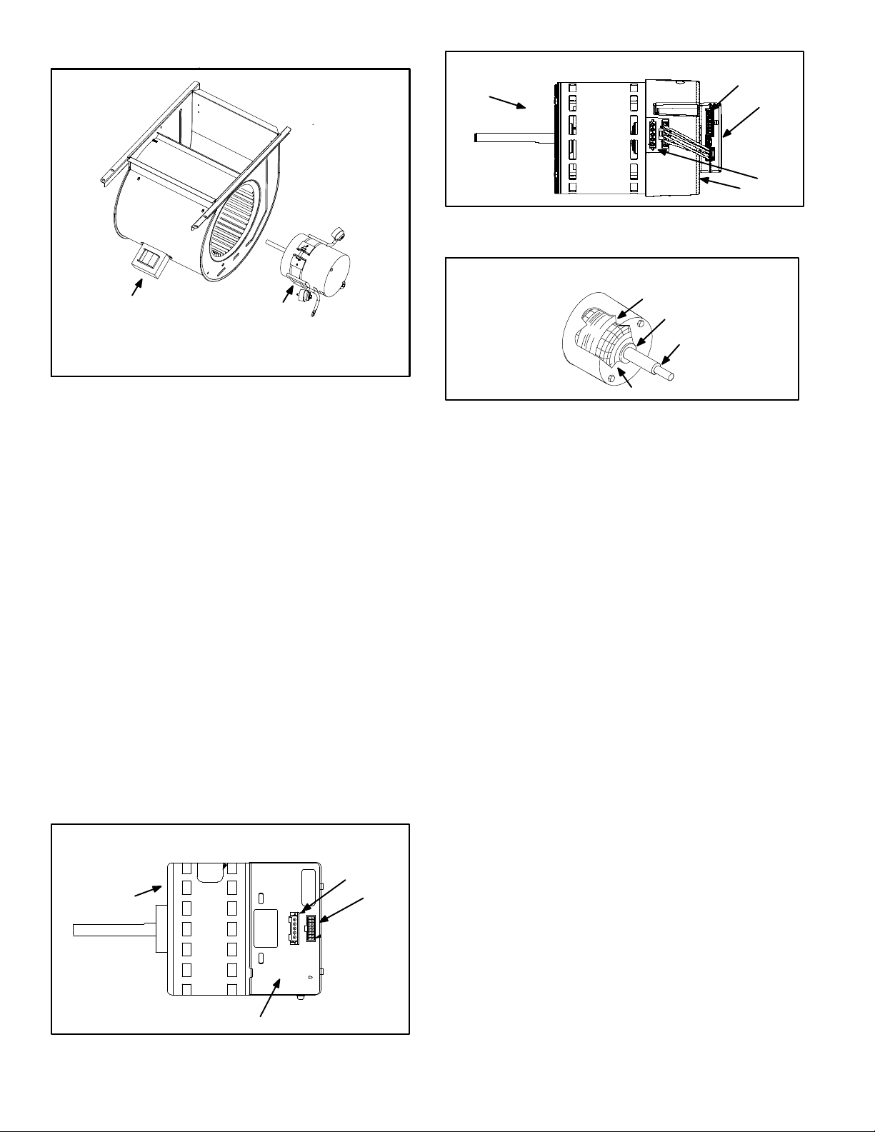
B- Indoor Blower Motor
Power Choke
(5 Ton Only)
To Remove Blower From Unit: Remove Bolts and
Wiring Jackplugs. Then Slide Out Front of Unit.
Blower Motor
(B3)
FIGURE 4
Blower Motor (B3)
Blower motors are manufactured by GenTeq and Nidec. See
figures 5 and 6. Motors operate the same and are only differ
ent in physical appearance. They are both three‐phase, elec
tronically controlled DC brushless motors (controller converts
single-phase AC to three-phase DC), with a permanent mag
net type rotor (figure 5). Because these motors have a per
manent magnet rotor it does not need brushes like conven
tional DC motors.
Internal components for both manufactured motors are simi
lar and shown in figure 7. The stator windings are split into
three poles which are electrically connected to the controller.
This arrangement allows motor wi ndings to tu r n on and off
in sequence by the controller.
NIDEC BLOWER MOTOR B3
MOTOR
J49
16X4W
J48
CONTROLLER
FIGURE 6
BLOWER MOTOR COMPONENTS
STATOR
(WINDINGS)
BEARING
OUTPUT
SHAFT
ROTOR
FIGURE 7
The controller uses sensing devices to sense what position
the rotor is in at any given time. By sensing the position of the
rotor and then switching the motor windings on and off in se
quence, the rotor shaft turns the blower.
All blower motors use single phase power. An external
run capacitor is not used. The motor uses permanently
lubricated ball‐type bearings.
Internal Operation
A solid‐state controller is attached to the motor. The
controller is primarily an AC to DC converter. Converted
DC power is used to drive the motor. The controller con
tains a microprocessor which monitors varying condi
tions inside the motor (such as motor workload). The
controller on the Emerson motor includes the 16X4W
control with three LED's PW, RX and TX located on the
face for troubleshooting. Figure 6 shows the location of
the 16X4W and table 5 the LED codes.
GenTeq BLOWER MOTOR B3
J48
MOTOR
CONTROLLER
J49
FIGURE 5
Each time the controller switches a stator winding (figure 7) on
and off, it is called a “pulse.” The length of time each pulse
stays on is called the “pulse width.” By varying the pulse width
(figure 10), the controller varies motor speed (called “pulse‐
width modulation”). This allows for precise control of motor
speed and allows the motor to compensate for varying load
conditions as sensed by the controller. In this case, the control
ler monitors the static workload on the motor and varies motor
rpm in order to maintain constant airflow (cfm).
The motor controller is driven by the Two-stage Variable
Speed Integrated control board. The board receives its
demand (PWM signal or fixed 24 VAC or VDC signal) from
optional controls such as the Harmony IIIt zoning system,
SignatureStatt, Efficiency Plus Humidity Control (CCB1) or a
conventional thermostat.
Page 12
Page 13
TABLE 5
Emerson Motor Only
PW
LEDRXLEDTXLED
Off Blink Blink
Blink Blink Blink Rotating Normal. PW blink is 100cfm/blink
Blink Off Blink
Off Off Off
Motor rpm is continually adjusted internally to maintain
constant cfm. The controller monitors the static work load on
the motor and motor amp‐draw to determine the amount of
rpm adjustment. Blower rpm may be adjusted any amount in
order to maintain a constant cfm as shown in Blower Ratings
Tables. The cfm remains relatively stable over a broad range
of static pressure. Since the blower constantly adjusts rpm to
maintain a specified cfm, motor rpm is not rated. Hence, the
terms “cool speed” , “heat speed ” or “speed tap” in this manu
al, on the unit wiring diagram and on blower B3, refer to blower
cfm regardless of motor rpm.
The unit control indicates the desired cfm. The blower will
maintain the desired cfm as long as external static pressure
does not exceed 0.8”. If the system exceeds this amount, the
blower may enter a “cut back”, mode wherein it then slows
down to protect itself from electrical damage. During this “cut
back” mode the unit control will still indicate the same desired
cfm regardless of actual motor rpm.
When Harmony is used, speed taps are overridden and a
PWM signal generated by the Harmony controller continuous
ly varies motor speed based upon zone demands.
Initial Power Up
When line voltage is applied to B3, there will be a large inrush
of power lasting less than 1/4 second. This inrush charges a
bank of DC filter capacitors inside the controller. If the discon
nect switch is bounced when the disconnect is closed, the dis
connect contacts may become welded. Try not to bounce the
disconnect switch when applying power to the unit.
Motor Start‐Up
When B3 begins start‐up, the motor gently vibrates back and
forth for a moment. This is normal. During this time the elec
tronic controller is determining the exact position of the rotor.
Once the motor begins turning, the controller slowly eases
the motor up to speed (this is called “soft‐start”). The motor
may take as long as 10‐15 seconds to reach full speed. If the
Motor
Blower
Not
Rotating
Not
Rotating
Not
Rotating
Turn off power for 1 minute then restart. If motor still
Verify power to the 16X4W. Turn off power then restart.
Action
Normal
Verify 16X4W and motor control hp match. Verify
power to motor control.
does not rotate replace the controller.
If LED's are still out, replace controller.
motor does not reach 200rpm within 13 seconds, the motor
shuts down. Then the motor will immediately attempt a re
start. The shutdown feature provides protection in case of a
frozen bearing or blocked blower wheel. The motor may at
tempt to start eight times. If the motor does not start after the
eighth try, the controller locks out. Reset controller by momen
tarily turning off power to unit.
The DC filter capacitors inside the controller are connected
electrically to the speed tap wires. The capacitors take
approximately 5 minutes to discharge when the disconnect
is opened. For this reason it is necessary to wait at least 5
minutes after turning off power to the unit before attempt
ing to change speed taps.
DANGER
Disconnect power from unit and
wait at least five minutes to allow
capacitors to discharge before at
tempting to adjust motor speed tap
settings. Failure to wait may cause
personal injury or death.
External Operation (Speed Tap Priority)
Figures 8 and 9 show the two quick‐connect jacks (J48 and
J49) which connect the motor to the ML296UHV. Jack J48
is the power plug and jack J49 connects the unit controls to
the motor.
Jack J48 is the power plug. Line voltage must be applied to
J48 pins 4 and 5 in order for the motor to operate. When
using 120VAC pins 1 and 2 must be jumpered.
Jack J49 connects the unit controls to the motor. The motor
assigns priority to J49 pin 2 so that if a call for cooling and a
call for heating are concurrent, heating call overrides and
the blower operates on high speed heating tap.
Page 13
Page 14
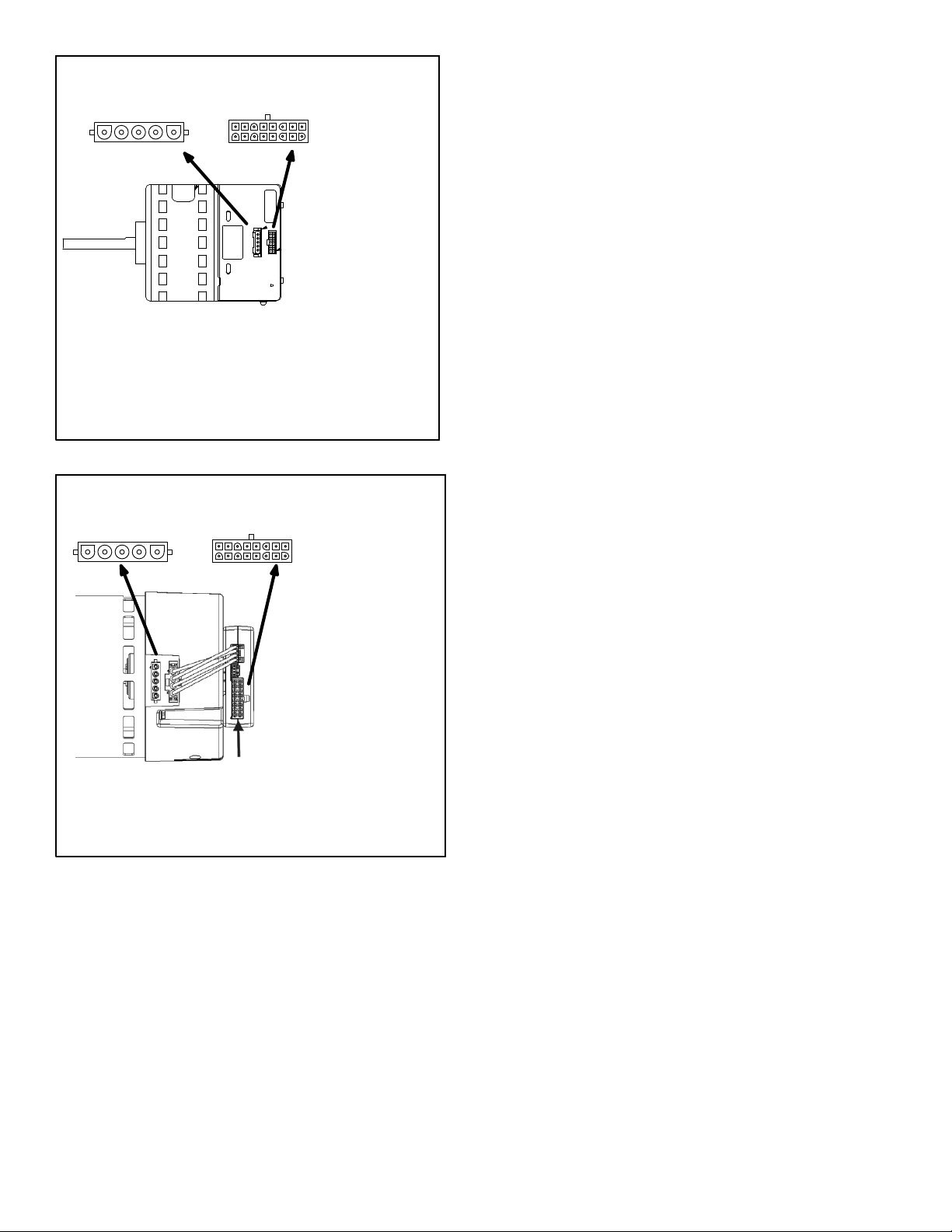
GenTeq HARNESS CONNECTORS
POWER
CONNECTOR J48
1
J48
PIN 1 ‐ Jumper PIN 1 to PIN2 for 120VAC line input only.
PIN 2 ‐ Jumper PIN 1 to PIN2 for 120VAC line input only.
PIN 3 ‐ Ground
PIN 4 ‐ AC Line
PIN 5 ‐ AC Line
CONTROL
CONNECTOR J49
16
J49
1
PIN 1 ‐ C1
PIN 2 ‐ W / W1
PIN 3 ‐ C2
PIN 4 - Delay
PIN 5 ‐ Cool
PIN 6 ‐ Y1
PIN 7 ‐ Adjust
PIN 8 ‐ Out
PIN 9 ‐ O
PIN 10 ‐ DS(PWM)
PIN 11 ‐ Heat
PIN 12 ‐ R
PIN 13 ‐ EM / W2
PIN 14 ‐ Y / Y2
PIN 15 ‐ G
PIN 16 ‐ Out +
FIGURE 8
EMERSON MOTOR HARNESS CONNECTORS
POWER
CONNECTOR J48
1
J48
PIN 1 ‐ Jumper PIN 1 to PIN2 for 120VAC line input only.
PIN 2 ‐ Jumper PIN 1 to PIN2 for 120VAC line input only.
PIN 3 ‐ Ground
PIN 4 ‐ AC Line
PIN 5 ‐ AC Line
CONTROL
CONNECTOR J49
16
J49
PIN 1 ‐ C1
1
PIN 2 ‐ W / W1
PIN 3 ‐ C2
PIN 4 - Delay
PIN 5 ‐ Cool
PIN 6 ‐ Y1
PIN 7 ‐ Adjust
PIN 8 ‐ Out
PIN 9 ‐ O
PIN 10 ‐ DS(PWM)
PIN 11 ‐ Heat
PIN 12 ‐ R
PIN 13 ‐ EM / W2
PIN 14 ‐ Y / Y2
PIN 15 ‐ G
PIN 16 ‐ Out +
FIGURE 9
Power Choke (L13)
A choke coil is used on 5 ton 1 hp units. The choke is lo
cated on the blower housing and is used to suppress transient
current spikes.
Precautions
If the furnace or its electronically controlled blower motor is im
properly or inadequately grounded, it may cause television in
terference (commonly known as RFI or radio frequency inter
ference).
This interference is caused by internal switching fre
quencies of the motor controller. TV interference may
show u p as small speck s or l ines which randomly appear
on the TV screen accompanied by pops or clicks in the sound.
Before attempting any service, make sure the indoor unit is
causing the interference. To check, disconnect power to indoor
unit then check TV for continued signs of interference.
TV interference may be stopped by making sure the mo
tor is solidly grounded to the cabinet (metal to metal) and
by making sure the cabinet is solidly grounded. If TV in
te r ference persist s, mak e sure the television (and all af
fected RF appliances) are moved away from the furnace. Also
make sure affected appliances are connected to a separate
electrical circuit.
Page 14
Page 15
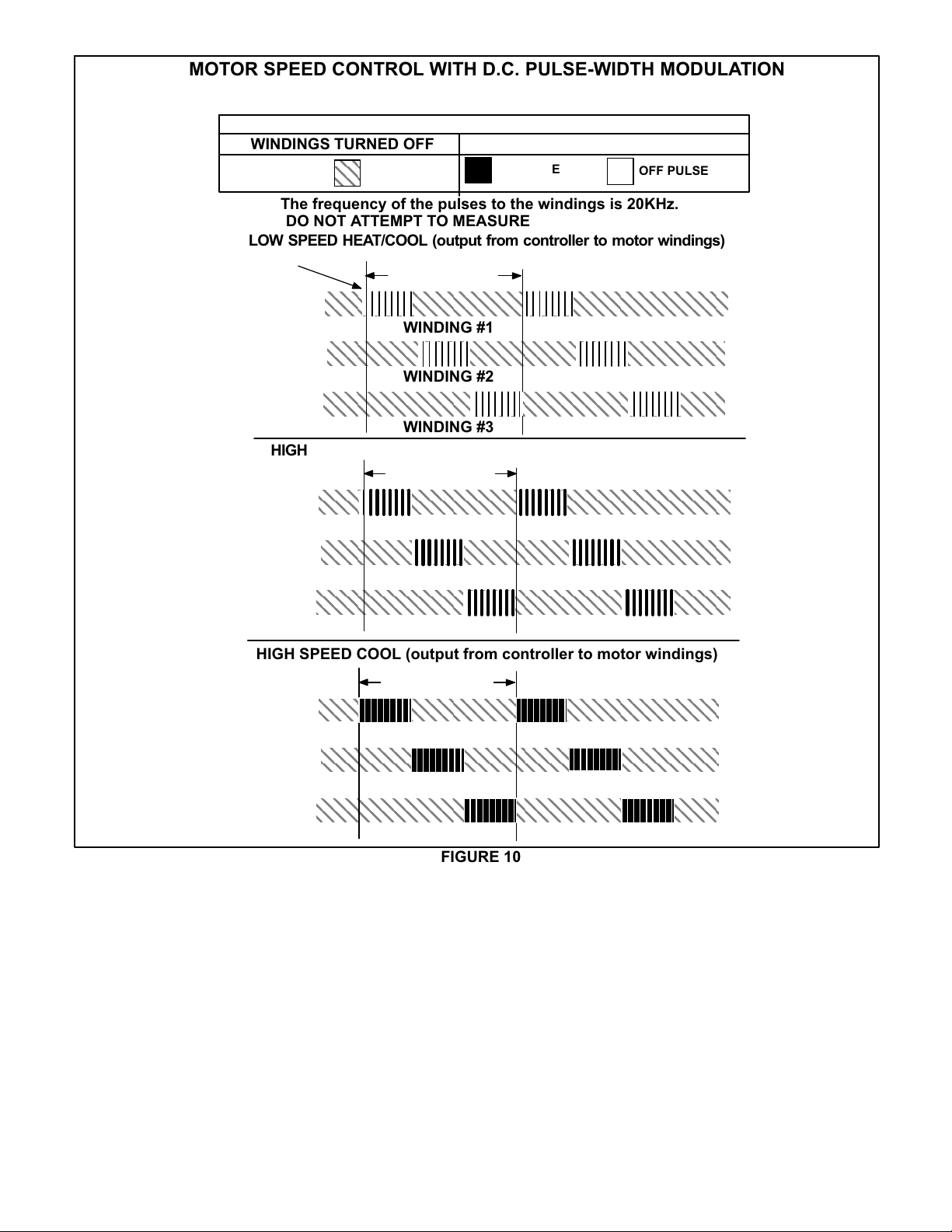
MOTOR SPEED CONTROL WITH D.C. PULSE‐WIDTH MODULATION
ÇÇ
Motor speed is determined by the size of the electrical pulse sent to
the motor windings. The longer the pulse, the faster the motor.
OUTPUT FROM CONTROLLER TO MOTOR WINDINGS
WINDINGS TURNED OFF
The frequency of the pulses to the windings is 20KHz.
DO NOT ATTEMPT TO MEASURE THESE VOLTAGES.
LOW SPEED HEAT/COOL (output from controller to motor windings)
One
Pulse
One revolution
325VDC
O volts
WINDING #1
325VDC
O volts
WINDING #2
325VDC
O volts
WINDING #3
HIGH SPEED HEAT (output from controller to motor windings)
One revolution
325VDC
O volts
WINDING #1
325VDC
O volts
WINDING #2
325VDC
O volts
WINDING #3
WINDINGS TURNED ON
ON PULSE
OFF PULSE
HIGH SPEED COOL (output from controller to motor windings)
One revolution
325VDC
O volts
WINDING #1
325VDC
O volts
WINDING #2
325VDC
O volts
WINDING #3
FIGURE 10
Page 15
Page 16
C- Heating Components
1. Ignitor
The ignitor is made of durable silicon nitride. Ignitor longev
ity is enhanced by controlling voltage to the ignitor. The in
tegrated control provides a regulated 120 volts to the igni
tor for a consistent ignition and long ignitor life. Ohm value
should be 39 to 70. See figure 11 for ignitor location and fig
ure 12 for ignitor check out.
NOTE - The ML296UHV(X) furnace contains electronic
components that are polarity sensitive. Make sure that the
furnace is wired correctly and is properly grounded.
2. Flame Sensor
A flame sensor is located on the left side of the burner sup
port. See figure 11. The sensor tip protrudes into the flame
envelope of the left-most burner. The sensor can be re
moved for service without removing any part of the burn
ers. During operation, flame is sensed by current passed
through the flame and sensing electrode. The SureLight
control allows the gas valve to remain open as long as
flame signal is sensed. See table 6 for flame signal.
TABLE 6
Flame Signal in Microamps
Normal
1.5 or greater 1.0 or less 0.5
3. Gas Valve
The valve (figure 49) is internally redundant to assure safe
ty shut-off. If the gas valve must be replaced, the same type
valve must be used.
24VAC terminals and gas control knob are located on the
valve. A wire harness connects the terminals from the gas
valve to the electronic ignition control. 24V applied to the termi
nals energizes the valve.
Inlet and outlet pressure taps are located on the valve. A regu
lator adjustment screw is located on the valve.
Low Drop Out
LPG change over kits are available from Lennox. Kits include
burner orifices and a gas valve.
4. Flame Rollout Switches (S47)
Flame rollout switch is a high temperature limit located on
top of the burner box, one on each side.- See figure 11. The
limit is a N.C. SPST manual‐reset limit. When S47 senses
rollout, the circuit breaks and the ignition control immedi
ately stops ignition and closes the gas valve. Rollout can be
caused by a blocked heat exchanger, flue or lack of com
bustion air. The switch is factory set to trip (open) at 210°F
and cannot be adjusted. The switch can be manually reset.
To manually reset a tripped switch, push the reset button lo
cated on the control.
5. Burners
All units use inshot burners. Burners are factory set and re
quire no adjustment. Always operate the unit with the burner
box front panel in place. Each burner uses an orifice (see
table 21 for orifice size) that is precisely matched to the burn
er input. Burners can be removed as a one piece assembly
for service. If burner assembly has been removed, it is critical
to align center of each burner to the center of the clamshell
when re-installing. See more detail in Section VI- MAINTE
NANCE.
6. Primary Limit Control (S10)
The primary limit (S10) is located in the heating vestibule pan
el. When excess heat is sensed in the heat exchanger, the
limit will open. If the limit is open, the furnace control energizes
the supply air blower and closes the gas valve. The limit auto
matically resets when unit temperature returns to normal. The
switch must reset within three minutes or the SureLight control
will go into Watch guard for one hour. The switch is factory
set and cannot be adjusted. The switch may have a different
set point for each unit model number. See Lennox Repair
Parts Handbook if limit switch must be replaced,
Page 16
Page 17

Intake Air Top Cap
Rollout Switch
ML296UHV HEATING COMPONENTS
Burner Assembly
Sensor
Rollout Switch
Ignitor
Burner Box Cover
Manifold And Gas Orifices
Two-Stage Gas Valve
FIGURE 11
Page 17
Page 18

Check ignitor circuit for correct resistance.
Test 1
Remove 4-pin plug from control.
Check ohms reading across terminals 1 and 5.
Reading should be between 39 and 70 ohms. If
value is correct, this is the only test needed.
If the reading on the meter is not correct, (0 or
infinity) then a second test is needed.
Meter
(set to ohms)
ML296UHV Ignitor Check
Integrated Control Detail
Seperate the 2-pin jack-plug near the manifold and check
Check ignitor for correct resistance.
resistance of ignitor at the plug. Reading should be
between 39 and 70 ohms. If the reading is correct, then
the problem is with the wiring between the jack-plug and
the control. If reading is not correct, the issue is the ignitor.
Test 2
Meter
(set to ohms)
Insert meter probes into terminals 1 and 5 (use small
Check ignitor for correct voltage
diameter probes in order not to damage plug).
Check voltage during 20 second ignitor warm up period.
Voltage should read 120 volts +
these values, check for correct supply voltage to furnace.
Test 3
10%. If voltage reads below
Integrated Control Detail
Meter
(set to AC volts)
Integrated Control Detail
FIGURE 12
Page 18
Page 19

7. Combustion Air Inducer (B6) and
Cold End Header Box
All ML296UHV(X) units use a two-stage combustion air in
ducer to move air through the burners and heat exchanger
during heating operation. The blower uses a 120VAC mo
tor. The motor operates during all heating operation and is
controlled by integrated control control A92. The inducer
also operates for 15 seconds before burner ignition (pre‐
purge) and for 5 seconds after the gas valve closes (post‐
purge). The inducer operates on low speed during firststage heat, then switches to high speed for second stage
heat.
NOTE - Each furnace model uses a unique CAI. Refer to
Lennox Repair Parts listing for correct inducer for replace
ment.
The combustion air inducer is installed on the cold end
header box. The cold end header box is a single piece
made of hard plastic. The box has an internal channel
where the combustion air inducer creates negative pres
sure at unit start up. The channel contains an orifice used
to regulate flow created by the combustion air inducer.
The box has pressure taps for the combustion air inducer
pressure switch hoses. The pressure switch measures
the pressure differential across the combustion air induc
er orifice or difference in the channel and the box. If re
placement is necessary the gaskets used to seal the
box to the vestibule panel and the combustion air in
ducer to the box, must also be replaced.
A proving switch connected to the combustion air inducer ori
fice plate is used to prove inducer operation. The combustion
air inducer orifice will be different for each model. See table 7
for orifice sizes. The pressure switch measures the pressure
differential across the combustion air inducer orifice. When
the proving switch opens, the furnace control (A92) immedi
ately closes the gas valve to prevent burner operation.
TABLE 7
ML296UHV(X) Unit C.A.I. Orifice Size
-045 0.618
-070 0.920
-090 0.920
-110 1.040
8. Combustion Air Inducer
Pressure Switch (S18)
ML296UHV(X) series units are equipped with a dual com
bustion air pressure switch (first and second stage) located
on the combustion air inducer orifice bracket. See figure 13.
The switch is connected to the combustion air inducer hous
ing by means of a flexible silicone hose. It monitors negative
air pressure in the combustion air inducer housing.
The switches are a single‐pole single‐throw proving switch
electrically connected to the integrated control. The purpose
of the switch is to prevent burner operation if the combustion
air inducer is not operating or if the flue becomes obstructed.
On heat demand (first or second stage) the switch senses
that the combustion air inducer is operating. It closes a cir
cuit to the integrated control when pressure inside the com
bustion air inducer decreases to a certain set point.
Set points vary depending on unit size. See table 8. The
pressure sensed by the switch is negative relative to atmo
spheric pressure. If the flue becomes obstructed during op
eration, the switch senses a loss of negative pressure
(pressure becomes more equal with atmospheric pres
sure) and opens the circuit to the furnace control and gas
valve. A bleed port on the switch allows relatively dry air in
the vestibule to purge switch tubing, to prevent condensate
build up.
COMBUSTION AIR PRESSURE SWITCH
Tap (negative - )
Tap (positive +)
Low Fire Switch
3/16 Terminals
" Terminals
1/4
High Fire Switch
FIGURE 13
NOTE - The switch is factory set and is not field adjustable.
It is a safety shut‐down control in the furnace and must not
be by-passed for any reason. If switch is closed or bypassed, the control will not initiate ignition at start up.
TABLE 8 0 - 4500'
ML296UHV(X)
Unit
-045 0.35 0.60
-070 0.50 0.85
-090 0.50 0.90
-110 0.45 0.90
Set Point Low
Heat
Set Point High Heat
TABLE 9 4501 - 7500'
ML296UHV(X)
Unit
-045 0.35 0.55
-070 0.45 0.75
-090 0.50 0.85
-110 0.45 0.81
Set Point Low
Heat
Set Point High Heat
TABLE 10 7501 - 10,000'
ML296UHV(X)
Unit
-045 0.35 0.50
-070 0.40 0.70
-090 0.45 0.81
-110 0.41 0.74
Set Point Low
Heat
Set Point High Heat
Page 19
Page 20

Pressure Switch Check
To check pressure switch differential, refer to figure 14 and
use the provided fittings and tubing to follow the steps be
low.
1 - Remove thermostat demand and allow unit to cycle
off.
2 - Remove the tubing from the negative side (red and black
or red) and positive side (black) of the pressure switch
(leave both connected to cold end header box).
3 - Take the 2” length square tubing and connect to the
positive (+) side of the pressure switch. Take the 10”
length square tubing and tee into the tubing from the
positive side of the cold end header box and the other
side of the 2” square tubing. Connect the other end of
the 10” square tubing the the positive (+) side of the
measuring device.
4 - Take a second piece the 2” length square tubing and
connect to the negative (-) side of the pressure switch.
Take a second piece of 10” length square tubing and
tee into the tubing from the negative (-) side of the cold
end header box and the other side of the 2” square tub
ing. Connect the other end of the 10” square tubing the
the negative (-) side of the measuring device.
PRESSURE SWITCH CHECK
Black Tubing
(positive +)
Te e
5 - Operate unit and observe manometer reading.
Readings will change as heat exchanger warms.
a. Take one reading immediately after start‐up.
b. Take a second reading after unit has reached steady
state (approximately 5 minutes). This will be the pres
sure differential.
The pressure differential should be at least
0.15” greater than those listed in the tables 8, 9 and
10. Readings in table are the set points or “break
points”.
6 - Remove thermostat demand and allow to cycle off.
7 - Replace original pressure switch tubing.
NOTE - Pressure differential values (set point) in table are
the ”break”, or ”open” specifications. ”Make”, or ”close”
pressure differentials are 0.15” greater than the set points
listed in table.
2” long Square
Tubing
Red and Black
or Red Tubing
(negative -)
10” Long Square Tubing
Measuring Device
FIGURE 14
Page 20
Page 21

II-PLACEMENT AND INSTALLATION
All pipe, fittings, primer and solvent cement must conform
with American National Standard Institute and the Ameri
can Society for Testing and Materials (ANSI/ASTM) stan
dards. The solvent shall be free flowing and contain no
lumps, undissolved particles or any foreign matter that ad
versely affects the joint strength or chemical resistance of
the cement. The cement shall show no gelation, stratifica
tion, or separation that cannot be removed by stirring. Re
fer to the table 11 below for approved piping and fitting ma
terials.
CAUTION
Solvent cements for plastic pipe are flammable liq
uids and should be kept away from all sources of
ignition. Do not use excessive amounts of solvent
cement when making joints. Good ventilation should
be maintained to reduce fire hazard and to minimize
breathing of solvent vapors. Avoid contact of ce
ment with skin and eyes.
Low temperature solvent cement is recommended during
cooler weather. Metal or plastic strapping may be used for
vent pipe hangers. Uniformly apply a liberal coat of PVC
primer for PVC or use a clean dry cloth for ABS to clean in
side socket surface of fitting and male end of pipe to depth
of fitting socket.
Canadian Applications Only - Pipe, fittings, primer
and solvent cement used to vent (exhaust) this ap
pliance must be certified to ULC S636 and supplied by a
single manufacturer as part of an approved vent (ex
haust) system. In addition, the first three feet of vent
pipe from the furnace flue collar must be accessible for
inspection.
PIPING AND FITTINGS SPECIFICATIONS
TABLE 11
Schedule 40 PVC (Pipe) D1785
Schedule 40 PVC (Cellular Core Pipe) F891
Schedule 40 PVC (Fittings) D2466
Schedule 40 CPVC (Pipe) F441
Schedule 40 CPVC (Fittings) F438
SDR-21 PVC or SDR-26 PVC (Pipe) D2241
SDR-21 CPVC or SDR-26 CPVC (Pipe) F442
Schedule 40 ABS Cellular Core DWV (Pipe) F628
Schedule 40 ABS (Pipe) D1527
Schedule 40 ABS (Fittings) D2468
ABS-DWV (Drain Waste & Vent)
(Pipe & Fittings)
PVC-DWV (Drain Waste & Vent)
Pipe & Fittings)
PRIMER & SOLVENT CEMENT
PVC & CPVC Primer F656
PVC Solvent Cement D2564
CPVC Solvent Cement F493
ABS Solvent Cement D2235
PVC/CPVC/ABS All Purpose Cement For
Fittings & Pipe of the same material
ABS to PVC or CPVC Transition Solvent
Cement
CANADA PIPE & FITTING & SOLVENT
CEMENT
PVC & CPVC Pipe and Fittings
PVC & CPVC Solvent Cement
ABS to PVC or CPVC Transition Cement
POLYPROPYLENE VENTING SYSTEM
PolyPro® by Duravent
InnoFlue® by Centrotherm ULC-S636
D2661
D2665
ASTM
SPECIFICATION
D2564, D2235, F493
D3138
MARKING
ULCS636
ULC-S636
IMPORTANT
ML296UHV exhaust and intake connections are
made of PVC. Use PVC primer and solvent cement
when using PVC vent pipe. When using ABS vent
pipe, use transitional solvent cement to make con
nections to the PVC fittings in the unit.
Use PVC primer and solvent cement or ABS solvent cement
meeting ASTM specifications, refer to Table 11. As an alter
nate, use all purpose cement, to bond ABS, PVC, or CPVC
pipe when using fittings and pipe made of the same materi
als. Use transition solvent cement when bonding ABS to ei
ther PVC or CPVC.
Page 21
Page 22

Input Size
045
070
090
110
OUTDOOR TERMINATION USAGE*
TABLE 12
STANDARD CONCENTRIC
Flush
Vent
Pipe
Dia. in.
2-1/2
2-1/2
2-1/2
2-1/2 YES YES
Mount
Kit
51W11
(US)
51W12
(CA)
2
3
2
3
2
3
2 YES YES YES
3 YES YES
3
YES YES
3
YES YES
3
YES YES
3
YES YES
3
YES YES
3
YES YES
3
YES YES YES
3
YES YES YES
3
YES YES YES
2 inch 3 inch 2 inch
22G44 (US)
4
30G28 (CA)
Wall Kit Wall Ring Kit
44J40
(US)
4
81J20 (CA)
1
YES
1
YES
1
YES
1
YES
1
YES
1
YES
15F74
1
YES
1
YES
1
YES
1
YES
1
YES
1
YES
1-1/2 inch 2 inch 3 inch
Field
Fabricated
5
YES
5
YES
5
YES
5
YES
5
YES
5
YES
5
YES YES YES
5
YES YES YES
5
YES YES YES
5
YES YES YES
5
YES YES YES
5
YES YES YES
71M80
(US)
4
44W92
(CA)
2
YES
2
YES
2
YES
2
YES
2
YES
2
YES
69M29
(US)
4
44W92
(CA)
60L46 (US)
4
44W93 (CA)
NOTE - Standard Terminations do not include any vent pipe or elbows external to the structure. Any vent pipe or elbows external to the structure must be included in total vent length
calculations. See vent length tables.
* Kits must be properly installed according to kit instructions.
1
Requires field-provided outdoor 1-1/2” exhaust accelerator.
2
Concentric kits 71M80 and 44W92 include 1-1/2” outdoor accelerator, when used with 045 and 070 input models.
3
Flush mount kits 51W11 and 51W12 includes 1-1/2 in. outdoor exhaust accelerator, required when used with 045, 070 and 090 input models.
4
Termination kits 30G28, 44W92, 44W93 and 81J20 are certified to ULC S636 for use in Canada only.
5
See table 17 for vent accelerator requirements.
NOTE - Time is critical at this stage. Do not allow prim
Joint Cementing Procedure
All cementing of joints should be done according to the
specifications outlined in ASTM D 2855.
er to dry before applying cement.
6 - Promptly apply solvent cement to end of pipe and in
side socket surface of fitting. Cement should be ap
plied lightly but uniformly to inside of socket. Take
DANGER
care to keep excess cement out of socket. Apply sec
ond coat to end of pipe.
DANGER OF EXPLOSION!
Fumes from PVC glue may ignite during system
check. Allow fumes to dissipate for at least 5 minutes
before placing unit into operation.
7 - Immediately after applying last coat of cement to pipe,
and while both inside socket surface and end of pipe
are wet with cement, forcefully insert end of pipe into
socket until it bottoms out. Turn PVC pipe 1/4 turn dur
1 - Measure and cut vent pipe to desired length.
2 - Debur and chamfer end of pipe, removing any ridges
or rough edges. If end is not chamfered, edge of pipe
may remove cement from fitting socket and result in a
leaking joint.
NOTE - Check the inside of vent pipe thoroughly for
any obstruction that may alter furnace operation.
3 - Clean and dry surfaces to be joined.
4 - Test fit joint and mark depth of fitting on outside of pipe.
5 - Uniformly apply a liberal coat of PVC primer for PVC or
use a clean dry cloth for ABS to clean inside socket
surface of fitting and male end of pipe to depth of fitting
socket.
ing assembly (but not after pipe is fully inserted) to dis
tribute cement evenly. DO NOT turn ABS or cellular
core pipe.
NOTE - Assembly should be completed within 20 sec
onds after last application of cement. Hammer blows
should not be used when inserting pipe.
8 - After assembly, wipe excess cement from pipe at end
of fitting socket. A properly made joint will show a
bead around its entire perimeter. Any gaps may indi
cate an improper assembly due to insufficient sol
vent.
9 - Handle joints carefully until completely set.
Page 22
Page 23

Venting Practices
Piping Suspension Guidelines
Conduct the following test while each appliance is operat
ing and the other appliances (which are not operating) re
main connected to the common venting system. If the
venting system has been installed improperly, you must
correct the system as indicated in the general venting re
quirements section.
SCHEDULE 40
PVC - 5'
all other pipe* - 3'
* See table 11 for allowable pipe.
NOTE - Isolate piping at the point where it exits the outside wall or
roof in order to prevent transmission of vibration to the structure.
NOTE - All horizontal runs of exhaust pipe must slope back to
ward unit a minimum of 1/4” (6mm) drop for each 12” (305mm).
Wall Thickness Guidelines
24” maximum
3/4” minimum
inside outside
FIGURE 15
9. In areas where piping penetrates joists or interior
walls, hole must be large enough to allow clearance on
all sides of pipe through center of hole using a hanger.
10. When furnace is installed in a residence where unit is
shut down for an extended period of time, such as a
vacation home, make provisions for draining conden
sate collection trap and lines.
Removal of the Furnace from Common Vent
In the event that an existing furnace is removed from a
venting system commonly run with separate gas ap
pliances, the venting system is likely to be too large to
properly vent the remaining attached appliances.
Wall
WARNING
CARBON MONOXIDE POISONING HAZARD
Failure to follow the steps outlined below for each
appliance connected to the venting system being
placed into operation could result in carbon mon
oxide poisoning or death.
The following steps shall be followed for each ap
pliance connected to the venting system being
placed into operation, while all other appliances
connected to the venting system are not in
operation:
1 - Seal any unused openings in the common venting sys
tem.
2 - Inspect the venting system for proper size and horizontal
pitch. Determine that there is no blockage, restriction,
leakage, corrosion, or other deficiencies which could
cause an unsafe condition.
3 - Close all building doors and windows and all doors be
tween the space in which the appliances remaining
connected to the common venting system are located
and other spaces of the building. Turn on clothes dry
ers and any appliances not connected to the common
venting system. Turn on any exhaust fans, such as
range hoods and bathroom exhausts, so they will oper
ate at maximum speed. Do not operate a summer ex
haust fan. Close fireplace dampers.
4 - Follow the lighting instructions. Turn on the appliance
that is being inspected. Adjust the thermostat so that
the appliance operates continuously.
5 - After the main burner has operated for 5 minutes, test
for leaks of flue gases at the draft hood relief opening.
Use the flame of a match or candle.
6 - After determining that each appliance connected to the
common venting system is venting properly, (step 3)
return all doors, widows, exhaust fans, fireplace damp
ers, and any other gas-burning appliances to their pre
vious mode of operation.
Page 23
Page 24

7 - If a venting problem is found during any of the preced
ing tests, the common venting system must be modi
fied to correct the problem.
Resize the common venting system to the minimum
vent pipe size determined by using the appropriate
tables in Appendix G. (These are in the current stan
dards of the National Fuel Gas Code ANSI Z223.1.
CHIMNEY
OR GAS
VENT
(Check sizing
for water
heater only)
FURNACE
(Replaced
by EL296)
If an ML296UHV furnace replaces a furnace which was
commonly vented with another gas appliance, the size of
the existing vent pipe for that gas appliance must be
checked. Without the heat of the original furnace flue prod
ucts, the existing vent pipe is probably oversized for the
single water heater or other appliance. The vent should be
checked for proper draw with the remaining appliance.
REPLACING FURNACE THAT
WAS PART OF A COMMON
VENT SYSTEM
WATER
HEATER
OPENINGS
(To Adjacent
Room)
FIGURE 16
Exhaust Piping (Figures 17, 19 and 20)
Route piping to outside of structure. Continue with installa
tion following instructions given in piping termination sec
tion.
quirements stated in the unit installation instruction – min
imum & maximum vent lengths, termination clearances,
etc. – apply and must be followed. Follow the instructions
provided with PoyPro by DuraVent and InnoFlue by Cen
trotherm venting system for assembly or if requirements
are more restrictive. The PolyPro by Duravent and In
noFlue by Centrotherm venting system must also follow
the uninsulated and unconditioned space criteria listed in
table 16.
The ML296UHV can be installed as either a Non-Direct
Vent or a Direct Vent gas central furnace.
NOTE - In Non‐Direct Vent installations, combustion air is
taken from indoors or ventilated attic or crawlspace and flue
gases are discharged outdoors. In Direct Vent installations,
combustion air is taken from outdoors and flue gases are
discharged outdoors.
Intake and exhaust pipe sizing -- Size pipe according to
tables 13 and
14. Count all elbows inside and outside the
home. Table 13 lists the minimum vent pipe lengths per
mitted. Table
14 lists the maximum pipe lengths permitted.
Regardless of the diameter of pipe used, the standard roof
and wall terminations described in section Exhaust Piping
Terminations should be used. Exhaust vent termination
pipe is sized to optimize the velocity of the exhaust gas as
it exits the termination. Refer to table 17.
In some applications which permit the use of several differ
ent sizes of vent pipe, a combination vent pipe may be
used. Contact Lennox' Application Department for assis
tance in sizing vent pipe in these applications.
NOTE - The exhaust collar on all models is sized to ac
commodate 2” Schedule 40 vent pipe. In horizontal ap
plications, any transition to exhaust pipe larger than 2”
must be made in vertical runs of the pipe. Therefore a 2”
elbow must be added before the pipe is transitioned to
any size larger than 2”. This elbow must be added to the
elbow count used to determine acceptable vent lengths.
Contact the Application Department for more information
concerning sizing of vent systems which include multiple
pipe sizes.
CAUTION
Do not discharge exhaust into an existing stack or
stack that also serves another gas appliance. If verti
cal discharge through an existing unused stack is re
quired, insert PVC pipe inside the stack until the end
is even with the top or outlet end of the metal stack.
CAUTION
The exhaust vent pipe operates under positive pres
sure and must be completely sealed to prevent leak
age of combustion products into the living space.
Vent Piping Guidelines
NOTE - Lennox has approved the use of DuraVent
Centrotherm manufactured vent pipe and terminations as
an option to PVC. When using the PolyPro
InnoFlue
®
by Centrotherm venting system the vent pipe re
®
by DuraVent or
®
and
Page 24
Horizontal Installation Offset Requirements
Exhaust Pipe
Horizontal
12” Max.
Gas Furnace
NOTE - All horizontal runs of exhaust pipe must slope back to
ward unit. A minimum of 1/4” (6mm) drop for each 12” (305mm)
of horizontal run is mandatory for drainage.
NOTE - Exhaust pipe MUST be glued to furnace exhaust fittings.
NOTE - Exhaust piping should be checked carefully to make
sure there are no sags or low spots.
12” Min.
FIGURE 17
Page 25

MINIMUM VENT PIPE LENGTHS
ML296UHV
MODEL
045, 070, 090, 110
*Any approved termination may be added to the minimum length listed.
TABLE 13
MIN. VENT LENGTH*
15 ft. or
5 ft. plus 2 elbows or
10 ft. plus 1 elbow
Use the following steps to correctly size vent pipe diameter.
Piping Size Process
What is the
furnace capacity?
1
045, 070, 090,
110
Which style termination
2
3
4
being used?
Standard or concentric?
See table 12.
Which needs
most elbows?
Intake or
exhaust?
How many elbows?
Count all elbows inside
and outside house.
Desired pipe size?
5
6
7
2”, 2-1/2”, 3”
What is the altitude of
the furnace installation?
Use table 14 or 15 to find
max intake or exhaust pipe
length. Includes all vent
pipe and elbows inside
and outside the house.
FIGURE 18
IMPORTANT
Do not use screens or perforated metal in exhaust or
intake terminations. Doing so will cause freeze-ups
and may block the terminations.
Page 25
Page 26

Maximum Allowable Intake or Exhaust Vent Length in Feet
TABLE 14
NOTE - Size intake and exhaust pipe length separately. Values in table are for Intake OR Exhaust, not combined total. Both Intake and Exhaust must be same pipe
size.
NOTE - Additional vent pipe and elbows used to terminate the vent pipe outside the structure must be included in the total vent length calculation.
Standard Termination at Elevation 0 - 4500 ft
Number Of 90°
Elbows Used
045 070 090 110 045 070 090 11 0 045 070 090 110
1 81 66 44 24 11 5 115 93 58 138 137 118 11 8
2 76 61 39 19 11 0 110 88 53 133 132 113 11 3
3 71 56 34 14 105 105 83 48 128 127 108 108
4 66 51 29
5 61 46 24 95 95 73 38 118 11 7 98 98
6 56 41 19 90 90 68 33 113 11 2 93 93
7 51 36 14 85 85 63 28 108 107 88 88
8 46 31
9 41 26 75 75 53 18 98 97 78 78
10 36 21 70 70 48 13 93 92 73 73
2” Pipe 2-1/2” Pipe 3” Pipe
Model Model Model
100 100 78 43 123 122 103 103
n/a
80 80 58 23 103 102 83 83
n/a
Standard Termination Elevation 4500 - 10,000 ft
Number Of 90°
Elbows Used
045 070 090 110 045 070 090 11 0 045 070 090 110
1 81 66 44
2 76 61 39 110 110 88 53 133 132 11 3 11 3
3 71 56 34 105 105 83 48 128 127 108 108
4 66 51 29 100 100 78 43 123 122 103 103
5 61 46 24 95 95 73 38 118 11 7 98 98
6 56 41 19 90 90 68 33 113 11 2 93 93
7 51 36 14 85 85 63 28 108 107 88 88
8 46 31
9 41 26 75 75 53 18 98 97 78 78
10 36 21 70 70 48 13 93 92 73 73
2” Pipe 2-1/2” Pipe 3” Pipe
Model Model Model
115 115 93 58 138 137 11 8 118
n/a
80 80 58 23 103 102 83 83
n/a
See concentric terminations next page.
Page 26
Page 27

Maximum Allowable Intake or Exhaust Vent Length in Feet
TABLE 14 Continued
Size intake and exhaust pipe length separately. Values in table are for Intake OR Exhaust, not combined total. Both Intake and Exhaust must be same pipe size.
Concentric Termination at Elevation 0 - 4500 ft
Number Of 90°
Elbows Used
045 070 090 11 0 045 070 090 11 0 045 070 090 11 0
1 73 58 42 22 105 105 89 54 121 121 114 11 4
2 68 53 37 17 100 100 84 49 116 116 109 109
3 63 48 32 12 95 95 79 44 111 111 104 104
4 58 43 27
5 53 38 22 85 85 69 34 101 101 94 94
6 48 33 17 80 80 64 29 96 96 89 89
7 43 28 12 75 75 59 24 91 91 84 84
8 38 23
9 33 18 65 65 49 14 81 81 74 74
10 28 13 60 60 44 n/a 76 76 69 69
2” Pipe 2-1/2” Pipe 3” Pipe
Model Model Model
90 90 74 39 106 106 99 99
n/a
70 70 54 19 86 86 79 79
n/a
Concentric Termination Elevation 4501 - 10,000 ft
Number Of 90°
Elbows Used
045 070 090 11 0 045 070 090 11 0 045 070 090 11 0
1 73 58 42
2 68 53 37 100 100 84 49 11 6 116 109 109
3 63 48 32 95 95 79 44 111 111 104 104
4 58 43 27 90 90 74 39 106 106 99 99
5 53 38 22 85 85 69 34 101 101 94 94
6 48 33 17 80 80 64 29 96 96 89 89
7 43 28 12 75 75 59 24 91 91 84 84
8 38 23
9 33 18 65 65 49 14 81 81 74 74
10 28 13 60 60 44 n/a 76 76 69 69
2” Pipe 2-1/2” Pipe 3” Pipe
Model Model Model
105 105 89 54 121 121 114 114
n/a
70 70 54 19 86 86 79 79
n/a
Page 27
Page 28

Maximum Allowable Exhaust Vent Lengths With Furnace Installed in a Closet or Basement Using Ventilated
TABLE 15
Attic or Crawl Space For Intake Air in Feet
NOTE - Size intake and exhaust pipe length separately. Values in table are for Intake OR Exhaust, not combined total. Both Intake and Exhaust must be same pipe
size.
NOTE - Additional vent pipe and elbows used to terminate the vent pipe outside the structure must be included in the total vent length calculation.
Standard Termination at Elevation 0 - 4500 ft
Number Of 90°
Elbows Used
045 070 090 110 045 070 090 11 0 045 070 090 110
1 71 56 34 14 100 100 78 43 11 8 11 7 98 98
2 66 51 29 9 95 95 73 38 11 3 11 2 93 93
3 61 46 24 4 90 90 68 33 108 107 88 88
4 56 41 19
5 51 36 14 80 80 58 23 98 97 78 78
6 46 31 9 85 75 63 18 93 92 73 73
7 41 26 4 70 70 48 13 88 87 68 68
8 36 21
9 31 16 60 60 38 3 78 77 58 58
10 26 11 55 55 33 n/a 73 72 53 53
2” Pipe 2-1/2” Pipe 3” Pipe
Model Model Model
85 85 63 28 103 102 83 83
n/a
65 65 43 8 83 82 63 63
n/a
Standard Termination Elevation 4500 - 10,000 ft
Number Of 90°
Elbows Used
045 070 090 110 045 070 090 11 0 045 070 090 110
1 71 56 34
2 66 51 29 95 95 73 38 113 11 2 93 93
3 61 46 24 90 90 68 33 108 107 88 88
4 56 41 19 85 85 63 28 103 102 83 83
5 51 36 14 80 80 58 23 98 97 78 78
6 46 31 9 85 85 53 18 93 92 73 73
7 41 26 4 70 70 48 13 88 87 68 68
8 36 21
9 31 16 60 60 38 3 78 77 58 58
10 26 11 55 55 33 n/a 73 72 53 53
2” Pipe 2-1/2” Pipe 3” Pipe
Model Model Model
100 100 78 43 118 11 7 98 98
n/a
65 65 43 8 83 82 63 63
n/a
Page 28
Page 29

TYPICAL EXHAUST AND INTAKE PIPE CONNECTIONS IN UPFLOW DIRECT OR
NON-DIRECT VENT APPLICATIONS
EXHAUST
2”
INTAKE
2”
EXHAUST INTAKE
TRANSITION
3”
*2”
2”
3”
TRANSITION
*2”
2”
or
DO NOT transition
from smaller to larger
pipe in horizontal runs
of exhaust pipe.
* When transitioning up in pipe size, use the shortest length of 2” PVC pipe possible.
FIGURE 19
2”
2”
TYPICAL EXHAUST AND INTAKE PIPE CONNECTIONS IN HORIZONTAL DIRECT OR NON-DIRECT VENT
APPLICATIONS
12” max.
EXHAUST
2”
INTAKE
EXHAUST
*2”
(RIGHT HAND DISCHARGE SHOWN)
2”
or
2”
2”
3”
*2”
2”
2”
TRANSITION
*2”
2”
or
2”
3”
*2”
45°
MAX
2”
*2”
2”
SIDE VIEW
45°
MAX
DO NOT transition
from smaller to larger
pipe in horizontal runs
of exhaust pipe.
INTAKE
* When transitioning up in pipe size, use the shortest length of 2” PVC pipe possible.
FIGURE 20
Page 29
Page 30

Intake Piping
The ML296UHV furnace may be installed in either direct
vent or non-direct vent applications. In non-direct vent
applications, when intake air will be drawn into the furnace
from the surrounding space, the indoor air quality must be
considered and guidelines listed in Combustion, Dilution
and Ventilation Air section must be followed.
Follow the next two steps when installing the unit in Direct
Vent applications, where combustion air is taken from
outdoors and flue gases are discharged outdoors. The
provided air intake screen must not be used in direct
vent applications (outdoors).
1 - Use transition solvent cement or a sheet metal screw
to secure the intake pipe to the inlet air connector.
2 - Route piping to outside of structure. Continue with
installation following instructions given in general
guidelines for piping terminations and intake and ex
haust piping terminations for direct vent sections. Re
fer to table
14 for pipe sizes.
TYPICAL AIR INTAKE PIPE CONNECTIONS
HORIZONTAL NON−DIRECT VENT APPLICATIONS
(Horizontal Right−Hand Air Discharge Application Shown)
PVC pipe
coupling
OR
INTAKE
DEBRIS
SCREEN
(Provided)
NOTE - Debris screen may be positioned straight out
(preferred) or with an elbow rotated to face down.
TYPICAL AIR INTAKE PIPE CONNECTIONS
UPFLOW NON−DIRECT
VENT APPLICATIONS
INTAKE
DEBRIS
SCREEN
(Provided)
NOTE - Debris screen and elbow may be rotated, so that
screen may be positioned to face forward or to either side.
FIGURE 21
FIGURE 22
Follow the next two steps when installing the unit in Non‐
Direct Vent applications where combustion air is taken
from indoors or ventilated attic or crawlspace and flue
gases are discharged outdoors.
1 - Use field-provided materials and the factory-provided
air intake screen to route the intake piping as shown in
figure 21 or 22. Maintain a minimum clearance of 3”
(76mm) around the air intake opening. The air intake
opening (with the protective screen) should always be
directed forward or to either side in the upflow position,
and either straight out or downward in the horizontal
position.
The air intake piping must not terminate too close
to the flooring or a platform. Ensure that the intake
air inlet will not be obstructed by loose insulation
or other items that may clog the debris screen.
2 - If intake air is drawn from a ventilated attic (figure 23)
or ventilated crawlspace (figure 24) the exhaust vent
length must not exceed those listed in table 15. If 3” di
ameter pipe is used, reduce to 2” diameter pipe at the
termination point to accommodate the debris screen.
3 - Use a sheet metal screw to secure the intake pipe to
the connector, if desired.
Page 30
Page 31

CAUTION
If this unit is being installed in an application with
combustion air coming in from a space serviced by
an exhaust fan, power exhaust fan, or other device
which may create a negative pressure in the space,
take care when sizing the inlet air opening. The in
let air opening must be sized to accommodate the
maximum volume of exhausted air as well as the
maximum volume of combustion air required for
all gas appliances serviced by this space.
(Inlet Air from Ventilated Attic and Outlet Air to Outside)
Roof Terminated
Exhaust Pipe
* See table 15 for maximum vent lengths
NOTE-The inlet and outlet air openings shall each have a free area
of at least one square inch per 4,000 Btu (645mm
hour of the total input rating of all equipment in the enclosure.
(Inlet Air from Ventilated Crawlspace and Outlet Air to Outside)
Roof Terminated
Exhaust Pipe
EQUIPMENT IN CONFINED SPACE
Ventilation Louvers
12 in.(305mm) Above
*Intake Debris
Screen
(Provided)
Furnace
2
per 1.17kW) per
FIGURE 23
EQUIPMENT IN CONFINED SPACE
Inlet Air
(Minimum
attic floor)
General Guidelines for Vent Terminations
In Non‐Direct Vent applications, combustion air is taken
from indoors or ventilated attic or crawlspace and the flue
gases are discharged to the outdoors. The ML296UHV is
then classified as a non‐direct vent, Category IV gas fur
nace.
In Direct Vent applications, combustion air is taken from
outdoors and the flue gases are discharged to the out
doors. The ML296UHV is then classified as a direct vent,
Category IV gas furnace.
In both Non‐Direct Vent and Direct Vent applications, the
vent termination is limited by local building codes. In the
absence of local codes, refer to the current National Fuel
Gas Code ANSI Z223-1/NFPA 54 in U.S.A., and current
CSA-B149 Natural Gas and Propane Installation Codes in
Canada for details.
Position termination according to location given in figure 26
or 27. In addition, position termination so it is free from any
obstructions and 12” above the average snow accumula
tion.
At vent termination, care must be taken to maintain
protective coatings over building materials (prolonged
exposure to exhaust condensate can destroy protective
coatings). It is recommended that the exhaust outlet not be
located within 6 feet (1.8m) of an outdoor AC unit because
the condensate can damage the painted coating.
NOTE - See table 16 for maximum allowed exhaust pipe
length without insulation in unconditioned space during
winter design temperatures below 32°F (0°C). If required
exhaust pipe should be insulated with 1/2” (13mm) Arma
flex or equivalent. In extreme cold climate areas, 3/4”
(19mm) Armaflex or equivalent may be necessary. Insula
tion must be protected from deterioration. Armaflex with
UV protection is permissable. Basements or other en
closed areas that are not exposed to the outdoor ambient
temperature and are above 32 degrees F (0°C) are to be
considered conditioned spaces.
Inlet Air
(Minimum
Ventilation
Louvers
(Crawl space)
Coupling or
3 in. to 2 in.
Transition
(Field Provided)
Furnace
12 in.(305mm)
Above crawl
space floor)
*Intake Debris Screen Provided)
* See table 15 for maximum vent lengths
NOTE-The inlet and outlet air openings shall each have a free area
of at least one square inch per 4,000 Btu (645mm
hour of the total input rating of all equipment in the enclosure.
2
per 1.17kW) per
FIGURE 24
IMPORTANT
Do not use screens or perforated metal in exhaust
terminations. Doing so will cause freeze-ups and
may block the terminations.
IMPORTANT
For Canadian Installations Only:
In accordance to CSA International B149 installation
codes, the minimum allowed distance between the
combustion air intake inlet and the exhaust outlet of
other appliances shall not be less than 12 inches
(305mm).
Page 31
Page 32

Maximum Allowable Exhaust Vent Pipe Length (in ft.)Without Insulation In Unconditioned Space For
TABLE 16
Winter Design Temperatures Two - Stage High Efficiency Furnace
Winter Design
Temperatures
32 to 21
(0 to -6)
1
°F (°C)
Vent Pipe
Diameter
045 070 090 110
PVC
2
PP PVC
2 in. 21 18 33 30 46 42 30 30
2-1/2 in. 16 N/A 26 N/A 37 N/A 36 N/A
Unit Input Size
2
PP PVC
2
PP PVC
2
PP
3 in. 12 12 21 21 30 30 29 29
2 in 11 9 19 17 28 25 27 24
20 to 1
(-7 to -17)
2-1/2 in. 7 N/A 14 N/A 21 N/A 20 N/A
3 in. N/A N/A 9 9 16 16 14 14
2 in. 6 4 12 10 19 16 18 15
0 to -20
(-18 to -29)
2-1/2 in. N/A N/A 7 N/A 13 N/A 12 N/A
3 in. N/A N/A N/A N/A 8 8 7 7
1Refer to 99% Minimum Design Temperature table provided in the current edition of the ASHRAE Fundamentals Handbook.
2
Poly-Propylene vent pipe (PP) by Duravent and Centrotherm.
NOTE - Concentric terminations are the equivalent of 5' and should be considered when measuring pipe length.
NOTE - Maximum uninsulated vent lengths listed may include the termination(vent pipe exterior to the structure) and cannot exceed 5 linear feet or the
maximum allowable intake or exhaust vent length listed in table 14 or 15 which ever is less.
NOTE - If insulation is required in an unconditioned space, it must be located on the pipe closest to the furnace. See figure25.
Conditioned
Space
Conditioned
Space
FIGURE 25
Pipe Insulation
Unconditioned
Space
Exhaust
Pipe
Intake
Pipe
Page 32
Page 33

VENT TERMINATION CLEARANCES
FOR NON-DIRECT VENT INSTALLATIONS IN THE US AND CANADA
INSIDE CORNER
DETAIL
G
D
A
E
B
L
C
Fixed
F
Closed
Operable
B
Operable
B
B
VENT TERMINAL
AIR SUPPLY INLET
US Installations
A =
Clearance above grade, veranda,
porch, deck or balcony
B =
Clearance to window or
door that may be opened
C =
Clearance to permanently
closed window
Vertical clearance to ventilated soffit
D =
located above the terminal within a
12 inches (305mm) or 12 in. (305mm)
above average snow accumulation.
4 feet (1.2 m) below or to side of opening;
1 foot (30cm) above opening
* 12”
* Equal to or greater than soffit depth.
horizontal distance of 2 feet (610 mm)
from the center line of the terminal
E =
F =
G =
H =
Clearance to unventilated soffit
Clearance to outside corner
Clearance to inside corner
Clearance to each side of center line ex
tended above meter / regulator assembly
I =
Clearance to service regulator
vent outlet
J =
Clearance to non-mechanical air
supply inlet to building or the com
bustion air inlet to any other ap
* Equal to or greater than soffit depth.
* No minimum to outside corner * No minimum to outside corner
**
3 feet (.9m) within a height 15 feet (4.5m)
*
above the meter / regulator assembly
* 3 feet (.9m)
4 feet (1.2 m) below or to side of opening;
1 foot (30 cm) above opening
pliance
K =
L =
Clearance to mechanical air sup
ply inlet
Clearance above paved sidewalk or
3 feet (.9m) above if within 10 feet
(3m) horizontally
7 feet (2.1m)†
paved driveway located on public property
Clearance under veranda, porch, deck or balcony
M =
1
In accordance with the current ANSI Z223.1/NFPA 54 Natural Fuel Gas Code
2
In accordance with the current CSA B149.1, Natural Gas and Propane Installation Code
† A vent shall not terminate directly above a sidewalk or paved driveway that is
located between two single family dwellings and serves both dwellings.
‡ Permitted only if veranda, porch, deck or balcony is fully open
on a minimum of two sides beneath the floor. Lennox recommends
avoiding this location if possible.
*12 inches (305mm)‡
FIGURE 26
H
B
Fixed
Closed
A
J
I
M
AREA WHERE TERMINAL
IS NOT PERMITTED
1
Canadian Installations
12 inches (305mm) or 12 in. (305mm)
above average snow accumulation.
6 inches (152mm) for appliances <10,000
Btuh (3kw), 12 inches (305mm) for
appliances > 10,000 Btuh (3kw) and
<100,000 Btuh (30kw), 36 inches (.9m)
for appliances > 100,000 Btuh (30kw)
* 12”
* Equal to or greater than soffit depth.
* Equal to or greater than soffit depth.
3 feet (.9m) within a height 15 feet (4.5m)
above the meter / regulator assembly
3 feet (.9m)
6 inches (152mm) for appliances <10,000
Btuh (3kw), 12 inches (305mm) for
appliances > 10,000 Btuh (3kw) and
<100,000 Btuh (30kw), 36 inches (.9m)
for appliances > 100,000 Btuh (30kw)
6 feet (1.8m)
7 feet (2.1m)†
12 inches (305mm)‡
*For clearances not specified in ANSI Z223.1/NFPA 54 or CSA
B149.1, clearance will be in accordance with local installation
codes and the requirements of the gas supplier and these instal
lation instructions.”
K
2
Page 33
Page 34

VENT TERMINATION CLEARANCES
FOR DIRECT VENT INSTALLATIONS IN THE US AND CANADA
INSIDE CORNER
DETAIL
G
D
A
E
B
L
C
Fixed
F
Closed
Operable
B
Operable
B
B
VENT TERMINAL
AIR SUPPLY INLET
US Installations
A =
B =
Clearance above grade, veranda,
porch, deck or balcony
Clearance to window or
door that may be opened
12 inches (305mm) or 12 in. (305mm)
above average snow accumulation.
6 inches (152mm) for appliances <10,000
Btuh (3kw), 9 inches (228mm) for ap
pliances > 10,000 Btuh (3kw) and <50,000
Btuh (15 kw), 12 inches (305mm) for ap
pliances > 50,000 Btuh (15kw)
C =
Clearance to permanently
* 12”
closed window
Vertical clearance to ventilated soffit
D =
located above the terminal within a
* Equal to or greater than soffit depth
horizontal distance of 2 feet (610mm)
from the center line of the terminal
E =
F =
G =
H =
Clearance to unventilated soffit
Clearance to outside corner
Clearance to inside corner
Clearance to each side of center line ex
tended above meter / regulator assembly
I =
Clearance to service regulator
vent outlet
J =
Clearance to non-mechanical air
supply inlet to building or the com
bustion air inlet to any other ap
pliance
* Equal to or greater than soffit depth * Equal to or greater than soffit depth
* No minimum to outside corner
*
3 feet (.9m) within a height 15 feet (4.5m)
above the meter / regulator assembly
*
3 feet (.9m)
6 inches (152mm) for appliances <10,000
Btuh (3kw), 9 inches (228mm) for ap
pliances > 10,000 Btuh (3kw) and <50,000
Btuh (15 kw), 12 inches (305mm) for ap
pliances > 50,000 Btuh (15kw)
K =
Clearance to mechanical air sup
ply inlet
L =
Clearance above paved sidewalk or
paved driveway located on public property
Clearance under veranda, porch, deck or balcony
M =
1
In accordance with the current ANSI Z223.1/NFPA 54 Natural Fuel Gas Code
2
In accordance with the current CSA B149.1, Natural Gas and Propane Installation Code
† A vent shall not terminate directly above a sidewalk or paved driveway that is located
between two single family dwellings and serves both dwellings.
‡ Permitted only if veranda, porch, deck or balcony is fully open on a minimum of
two sides beneath the floor. Lennox recommends avoiding this location if possible.
3 feet (.9m) above if within 10 feet
(3m) horizontally
* 7 feet (2.1m)
*12 inches (305mm)‡
FIGURE 27
H
B
Fixed
Closed
A
J
I
M
K
AREA WHERE TERMINAL
IS NOT PERMITTED
1
Canadian Installations
2
12 inches (305mm) or 12 in. (305mm)
above average snow accumulation.
6 inches (152mm) for appliances <10,000
Btuh (3kw), 12 inches (305mm) for
appliances > 10,000 Btuh (3kw) and
<100,000 Btuh (30kw), 36 inches (.9m)
for appliances > 100,000 Btuh (30kw)
* 12”
* Equal to or greater than soffit depth* Equal to or greater than soffit depth
* No minimum to outside corner
*
3 feet (.9m) within a height 15 feet (4.5m)
above the meter / regulator assembly
3 feet (.9m)
6 inches (152mm) for appliances <10,000
Btuh (3kw), 12 inches (305mm) for
appliances > 10,000 Btuh (3kw) and
<100,000 Btuh (30kw), 36 inches (.9m)
for appliances > 100,000 Btuh (30kw)
6 feet (1.8m)
7 feet (2.1m)†
12 inches (305mm)‡
*For clearances not specified in ANSI Z223.1/NFPA 54 or CSA
B149.1, clearance will be in accordance with local installation
codes and the requirements of the gas supplier and these
installation instructions.”
Page 34
Page 35

Details of Intake and Exhaust Piping Terminations for
Direct Vent Installations
NOTE - In Direct Vent installations, combustion air is tak
en from outdoors and flue gases are discharged to out
doors.
NOTE - Flue gas may be slightly acidic and may adversely
affect some building materials. If any vent termination is
used and the flue gasses may impinge on the building ma
terial, a corrosion-resistant shield (minimum 24 inches
square) should be used to protect the wall surface. If the
optional tee is used, the protective shield is recommended.
The shield should be constructed using wood, plastic,
sheet metal or other suitable material. All seams, joints,
cracks, etc. in the affected area should be sealed using an
appropriate sealant. See figure 36.
Intake and exhaust pipes may be routed either horizontally
through an outside wall or vertically through the roof. In at
tic or closet installations, vertical termination through the
roof is preferred. Figures 28 through 35 show typical
terminations.
1. Intake and exhaust terminations are not required to be
in the same pressure zone. You may exit the intake on
one side of the structure and the exhaust on another
side (figure 29). You may exit the exhaust out the roof
and the intake out the side of the structure (figure 30).
2. Intake and exhaust pipes should be placed as close
together as possible at termination end (refer to il
lustrations). Maximum separation is 3” (76MM) on roof
terminations and 6” (152MM) on side wall termina
tions.
NOTE - When venting in different pressure zones, the
maximum separation requirement of intake and ex
haust pipe DOES NOT apply.
3. On roof terminations, the intake piping should termi
nate straight down using two 90° elbows (See figure
28).
4. Exhaust piping must terminate straight out or up as
shown. A reducer may be required on the exhaust pip
ing at the point where it exits the structure to improve
the velocity of exhaust away from the intake piping.
See table 17.
NOTE - Care must be taken to avoid recirculation of
exhaust back into intake pipe.
5. On field-supplied terminations for side wall exit, ex
haust piping may extend a maximum of 12 inches
(305MM) for 2” PVC and 20 inches (508MM) for 3”
(76MM) PVC beyond the outside wall. Intake piping
should be as short as possible. See figure 36.
6. On field-supplied terminations, a minimum distance
between the end of the exhaust pipe and the end of
the intake pipe without a termination elbow is 8” and a
minimum distance of 6” with a termination elbow. See
figure 36.
Inches(MM)
8” (203MM) MIN
12” (305MM) ABOVE
AVERAGE SNOW
ACCUMULATION
3” (76MM) OR
2” (51MM) PVC
PROVIDE SUPPORT
FOR INTAKE AND
EXHAUST LINES
DIRECT VENT ROOF TERMINATION KIT
3”(76MM) MAX.
(15F75 or 44J41)
SIZE TERMINATION
PIPE PER TABLE 17.
UNCONDITIONED
ATTIC SPACE
FIGURE 28
Exiting Exhaust and Intake Vent
(different pressure zones)
Exhaust
Pipe
Furnace
(Minimum 12 in.
305 MM) above
grade or snow
accumulation
FIGURE 29
Exiting Exhaust and Intake Vent
(different pressure zones)
Roof T
erminated
Exhaust Pipe
Furnace
(Minimum 12 in.
305 MM) above
grade or snow
FIGURE 30
TABLE 17
EXHAUST PIPE TERMINATION SIZE REDUCTION
ML296UHV
MODEL
*045 and 070
*090 2” (51MM)
110 2” (51MM)
Termination
Pipe Size
1-1/2” (38MM)
Inlet Air
Inlet Air
accumulation
Page 35
Page 36

7. If intake and exhaust piping must be run up a side wall
to position above snow accumulation or other ob
structions, piping must be supported. At least one
bracket must be used within 6” from the top of the el
bow and then every 24” (610mm) as shown in figure
36, to prevent any movement in any direction. When
exhaust and intake piping must be run up an outside
wall, the exhaust piping must be terminated with pipe
sized per table 17.The intake piping may be equipped
with a 90° elbow turndown. Using turndown will add 5
feet (1.5m) to the equivalent length of the pipe.
*ML296UHV-045, -070 and -090 units with the flush mount
termination must use the 1-1/2”accelerator supplied with the
kit.
8. A multiple furnace installation may use a group of up to
four terminations assembled together horizontally, as
shown in figure 34.
9. A multiple furnace installation may use a group of up to
four terminations assembled together horizontally, as
shown in figure 34.
2” EXTENSION FOR 2” PVC
PIPE1” EXTENSION FOR 3”
PVC PIPE
FURNACE
4''
EXHAUST
PIPE
FURNACE
INTAKE
PIPE
GLUE EXHAUST
END FLUSH INTO
TERMINATION
FLAT
SIDE
1-1/2” ACCELERATOR
FLUSH-MOUNT SIDE WALL TERMINATION
51W11 (US) or 51W12 (Canada)
FIGURE 31
1 1/2” (38mm) accelerator
EXHAUST
12” (305mm)
Minimum
Above Average
Snow
Accumulation
VENT
provided on 71M80 & 44W92
kits for ML296UHV045P24B,
070P24B & 070P36B
INTAKE
AIR
FLASHING
(Not Furnished)
SHEET METAL STRAP
(Clamp and sheet metal strap
must be field installed to support
the weight of the termination kit.)
CLAMP
FIELD-PROVIDED
REDUCER MAY BE REQUIRED
TO ADAPT LARGER VENT
PIPE SIZE TO TERMINATION
DIRECT VENT CONCENTRIC ROOFTOP TERMINATION
71M80, 69M29 or 60L46 (US)
44W92 or 44W93 (Canada)
FIGURE 32
FIELD-PROVIDED
REDUCER MAY BE REQUIRED
TO ADAPT LARGER VENT
PIPE SIZE TO TERMINATION
EXHAUST
OUTSIDE
WALL
INTAKE
AIR
VENT
INTAKE
AIR
CLAMP
(Not Furnished)
INTAKE
AIR
12” (305mm) Min.
above grade or
average snow
accumulation.
GRADE
DIRECT VENT CONCENTRIC WALL TERMINATION
71M80, 69M29 or 60L46 (US)
44W92 or 44W93 (Canada)
FIGURE 33
EXHAUST
VENT
INTAKE
AIR
Inches (MM)
optional intake elbow
5”
(127MM)
18” MAX.
(457MM)
EXHAUST VENT
INTAKE
AIR
12”
(305MM)
5-1/2”
(140mm)
Front View
12” (305MM) Min.
above grade or
average snow
accumulation.
Side View
OPTIONAL VENT TERMINATION FOR MULTIPLE UNIT
INSTALLATION OF DIRECT VENT WALL TERMINATION KIT
(30G28 or 81J20)
FIGURE 34
ML296UHV DIRECT VENT APPLICATION
USING EXISTING CHIMNEY
STRAIGHT-CUT OR
3”-8”
(76MM-203MM)
ANGLE-CUT IN DIRECTION
OF ROOF SLOPE *
8” - 12”
(203MM - 305MM)
Minimum 12” (305MM)
above chimney top
plate or average snow
accumulation
NOTE - Do not discharge exhaust gases directly into any
chimney or vent stack. If vertical discharge through an
existing unused chimney or stack is required, insert pip
ing inside chimney until the pipe open end is above top
of chimney and terminate as illustrated. In any exterior
portion of chimney, the exhaust vent must be insulated.
INTAKE PIPE
INSULATION (optional)
SHEET
METAL TOP
PLATE
INSULATE
TO FORM
SEAL
SHOULDER OF FITTINGS
PROVIDE SUPPORT
OF PIPE ON TOP PLATE
3” - 8”
(76MM-
203MM)
FIGURE 35
EXHAUST
VENT
ALTERNATE
INTAKE PIPE
EXTERIOR
PORTION OF
CHIMNEY
Page 36
Page 37

NOTE − FIELD−PROVIDED
REQUIRED TO ADAPT
LARGER VENT PIPE SIZE
C1
* WALL
SUPPORT
C1
B
2
B
2
REDUCER MAY BE
TO TERMINATION
A
D
B
STRAIGHT
Intake
Elbow
D
B
C2
A
A− Minimum clearance
above grade or average
snow accumulation
B− Maximum horizontal
separation between
intake and exhaust
C1 -Minimum from end of
exhaust to inlet of intake
C2 -Minimum from end of
exhaust to inlet of intake
APPPLICATION
D− Maximum exhaust
pipe length
E
D
E
B
A
C2
D
B
A
EXTENDED
APPLICATION
E− Maximum wall support
distance from top of each
pipe (intake/exhaust)
See maximum allowable venting tables for venting
lengths with this arrangement.
* Use wall support every 24” (610 mm). Use two
wall supports if extension is greater than
24” (610 mm) but less than 48” (1219 mm).
NOTE − One wall support must be within 6” (152 mm)
from top of each pipe (intake and exhaust) to prevent
movement in any direction.
ALTERNATE TERMINATIONS (TEE & FORTY−FIVE DEGREE ELBOWS ONLY)
FIELD FABRICATED WALL TERMINATION
D
B
Exhaust
D
1
C
A
D
E
C
1
12”
Intake
Elbow
C
A
E
B
C
2
A
A
1
The exhaust termination tee should be connected to the 2” or 3” PVC flue pipe as shown in the illustration. In
horizontal tee applications there must be be a minimum of 3 ft away from covered patios or any living ares and
cannot be within 3 ft of a window. Do not use an accelerator in applications that include an exhaust termination
tee. The accelerator is not required.
2
As required. Flue gas may be acidic and may adversely affect some building materials. If a side wall vent
termination is used and flue gases will impinge on the building materials, a corrosion−resistant shield
(24 inches square) should be used to protect the wall surface. If optional tee is used, the protective shield
is recommended. The shield should be constructed using wood, sheet metal or other suitable material.
All seams, joints, cracks, etc. in affected area, should be sealed using an appropriate sealant.
3
Exhaust pipe 45° elbow can be rotated to the side away from the combustion air inlet to direct exhaust
away from adjacent property. The exhaust must never be directed toward the combustion air inlet.
3
D
1
12”
A− Clearance above
grade or average snow
accumulation
B− Horizontal
separation between
intake and exhaust
C− Minimum from
end of exhaust to
inlet of intake
D− Exhaust pipe length
E− Wall support distance
from top of each pipe
(intake/exhaust)
Front View of
Intake and Exhaust
Intake
Exhaust
2” (51mm)
Vent Pipe
12” (305 mm)
12” (305 mm)
6” (152 mm)
2” (51MM)
Vent Pipe
12” (305 mm) Min. 12” (305 mm) Min.
6” (152 mm) Min.
24” (610 mm) Max.
9” (227 mm) Min.
12” (305 mm) Min.
16” (405 mm) Max.
6” (152 mm) Max.
3” (76mm)
Vent Pipe
12” (305 mm)
6” (152 mm)6” (152 mm)
8” (203 mm)8” (203 mm)
6” (152 mm)6” (152 mm)
20” (508 mm)
6” (152 mm)
3” (76MM)
Vent Pipe
6” (152 mm) Min.
24” (610 mm) Max.
9” (227 mm) Min.
12” (305 mm) Min.
20” (508 mm) Max.
6” (152 mm) Max.
FIGURE 36
Page 37
Page 38

Details of Exhaust Piping Terminations for Non‐Direct
Vent Applications
Exhaust pipes may be routed either horizontally through an
outside wall or vertically through the roof. In attic or closet
installations, vertical termination through the roof is pre
ferred. Figures 37 and 38 show typical terminations.
1. Exhaust piping must terminate straight out or up as
shown. The termination pipe must be sized as listed in
table 17.The specified pipe size ensures proper
velocity required to move the exhaust gases away
from the building.
2. On field supplied terminations for side wall exit, ex
haust piping may extend a maximum of 12 inches
(305MM) for 2” PVC and 20 inches (508MM) for 3”
(76MM) PVC beyond the outside wall.
ML296UHV NON-DIRECT VENT APPLICATION
USING EXISTING CHIMNEY
STRAIGHT-CUT OR
ANGLE-CUT IN DIRECTION
OF ROOF SLOPE
Minimum 12” (305MM)
above chimney top
plate or average snow
accumulation
SHEET
METAL TOP
PLATE
INSULATE
TO FORM
SEAL
SHOULDER OF FITTINGS
PROVIDE SUPPORT
OF PIPE ON TOP PLATE
EXTERIOR
PORTION OF
CHIMNEY
12” (305MM)
ABOVE AVE.
SNOW
ACCUMULATION
3” (76MM) OR
2” (51MM) PVC
PROVIDE SUPPORT
FOR EXHAUST LINES
NON-DIRECT VENT ROOF TERMINATION KIT
(15F75 or 44J41)
UNCONDITIONED
ATTIC SPACE
FIGURE 37
3. If exhaust piping must be run up a side wall to position
above snow accumulation or other obstructions, pip
ing must be supported every 24 inches (610MM).
When exhaust piping must be run up an outside wall,
any reduction in exhaust pipe size must be done after
the final elbow.
4. Distance between exhaust pipe terminations on mul
tiple furnaces must meet local codes.
Crawl Space and Extended Horizontal Venting
Lennox provides kit 51W18 to install 2” or 3” PVC exhaust
piping through the floor joists and into the the crawl space.
See figure 39.
This kit can also be used as a supplemental drain for instal
lations with condensate run back in the vent pipe (ie. long
horizontal runs, unconditioned spaces, etc.).
NOTE - Do not discharge exhaust gases directly into any chimney or vent stack. If ver
tical discharge through an existing unused chimney or stack is required, insert piping
inside chimney until the pipe open end is above top of chimney and terminate as illus
trated. In any exterior portion of chimney, the exhaust vent must be insulated.
FIGURE 38
Venting In A Crawl Space
Basement Floor
KIT 51W81
(USA)
KIT 51W81
(CANADA)
FIGURE 39
Page 38
Page 39

Condensate Piping
This unit is designed for either right‐ or left‐side exit of con
densate piping in upflow applications. In horizontal applica
tions, the condensate trap must extend below the unit. An
8” service clearance is required for the condensate trap.
Refer to figures 40 and 42 for condensate trap locations.
Figure 48 shows trap assembly using 1/2” PVC or 3/4”
PVC.
NOTE - If necessary the condensate trap may be installed
up to 5’ away from the furnace. Use PVC pipe to connect
trap to furnace condensate outlet. Piping from furnace
must slope down a minimum of 1/4” per ft. toward trap.
1 - Determine which side condensate piping will exit the
unit, location of trap, field-provided fittings and length of
PVC pipe required to reach available drain.
2 - Use a large flat head screw driver or a 1/2” drive socket
extension and remove plug (figure 40) from the cold
end header box at the appropriate location on the side
of the unit. Install provided 3/4 NPT street elbow fitting
into cold end header box. Use Teflon tape or appropri
ate pipe dope.
NOTE - Cold end header box drain plugs are factory in
stalled. Check the unused plug for tightness to prevent
leakage.
3 - Install the cap over the clean out opening at the base
of the trap. Secure with clamp. See figure 48.
4 - Install drain trap using appropriate PVC fittings, glue
all joints. Glue the provided drain trap as shown in fig
ure 48. Route the condensate line to an open drain.
Condensate line must maintain a 1/4” downward slope
from the furnace to the drain.
5 - Figures 43 and 44 show the furnace and evaporator
coil using a separate drain. If necessary the conden
sate line from the furnace and evaporator coil can
drain together. See figures 45, 46 and 47.
Upflow furnace (figure 46) - In upflow furnace applica
tions the field provided vent must be a minimum 1” to a
maximum 2” length above the condensate drain outlet
connection. Any length above 2” may result in a
flooded heat exchanger if the combined primary drain
line were to become restricted.
Horizontal furnace (figure 47) - In horizontal furnace
applications the field provided vent must be a mini
mum 4” to a maximum 5” length above the condensate
drain outlet connection. Any length above 5” may re
sult in a flooded heat exchanger if the combined pri
mary drain line were to become restricted.
CONDENSATE TRAP AND PLUG LOCATIONS
(Unit shown in upflow position)
Trap
(same on
right side)
1-1/2 in.
Plug
(same on left side)
NOTE - In upflow applications where side return
air filter is installed on same side as the conden
sate trap, filter rack must be installed beyond
condensate trap or trap must be re-located to
avoid interference.
FIGURE 40
NOTE - In horizontal applications it is recommended to
install a secondary drain pan underneath the unit and
trap assembly.
NOTE - Appropriately sized tubing and barbed fitting
may be used for condensate drain. Attach to the drain
on the trap using a hose clamp. See figure 41.
Field Provided Drain Components
Elbow
Barbed Fitting
Tubing
Hose Clamp
FIGURE 41
Page 39
Page 40

CAUTION
Do not use copper tubing or existing copper conden
sate lines for drain line.
6 - If unit will be started immediately upon completion of
installation, prime trap per procedure outlined in Unit
Start-Up section.
CONDENSATE TRAP LOCATIONS
(Unit shown in upflow position with remote trap)
FieldProvidedVent
Min. 1” AboveCondensate
Drain
Connection
1”
Min.
2” Max.
*5’ max.
PVCPipeOnly
Condensate line must slope downward away from the
trap to drain. If drain level is above condensate trap,
condensate pump must be used. Condensate drain
line should be routed within the conditioned space to
avoid freezing of condensate and blockage of drain
line. If this is not possible, a heat cable kit may be used
on the condensate trap and line. Heating cable kit is
available from Lennox in various lengths; 6 ft. (1.8m) kit no. 26K68; 24 ft. (7.3m) - kit no. 26K69; and 50 ft.
(15.2m) - kit no. 26K70.
ML296UHV With Evaporator
Coil Using A Separate Drain
Evaporator drain
line required
(Trap at coil is optional)
Field Provided Vent
(1” min. 2” max. above
condensate connection)
Trap can be installed a
maximum 5' from furnace
To Drain
*Piping from furnace must slope down a minimum of
1/4” per ft. toward trap.
FIGURE 42
ML296UHV with Evaporatoir Coil Using a Separate Drain
(Unit shown in horizontal left-hand discharge position)
Evaporator
Coil
Condensate
DrainConnection
Condensate
DrainConnection
FIGURE 43
Field Provided Vent
(4” min. to 5” max. above
condensate connection)
4”min
5”max
5’ max.
PVC Pipe Only
Drain
Pan
(Trap at coil is optional)
Piping from furnace and evaporator coil must slope down a minimum 1/4” per ft. toward trap
FIGURE 44
IMPORTANT
When combining the furnace and evaporator
coil drains together, the A/C condensate drain
outlet must be vented to relieve pressure in or
der for the furnace pressure switch to operate
properly.
.
Page 40
Page 41

Condensate Trap With Optional Overflow Switch
From Evaporator Coil
Optional
Field Provided Vent
1” min. 2” max. above
condensate drain.
FurnaceCondensate
Drain
Connection
ML296UHV with Evaporator
Coil Using a Common Drain
(Trap at coil is optional)
(1” min. to 2”Max.above
condensatedrain connection)
Condensate
Drain
Connection
Evaporator drain
line required
Drain
Pan
FIGURE 45
FIGURE 46
ML296UHV with Evaporator Coil Using a Common Drain
(Unit shown in horizontal left−hand discharge position)
Evaporator
Coil
4”min
5”max
5’ max.
PVC Pipe Only
CondensateDrain
Connection
(Trap at coil is optional)
Piping from furnace and evaporator coil must slope down a minimum 1/4” per ft. toward trap
FIGURE 47
(4” min. to 5” Max.above
condensatedrain
connection)
Page 41
Page 42

TRAP / DRAIN ASSEMBLY USING 1/2” PVC OR 3/4” PVC
Optional Condensate Drain Connection
Adapter 3/4 inch slip X
3/4 inch mpt (not furnished)
90° Street Elbow
3/4 inch PVC
(not furnished)
Condensate Drain
Connection In Unit
90° Street Elbow
3/4 inch PVC
( furnished)
To
Trap
Optional Drain Piping FromTrap
Drain Assembly for 1/2 inch Drain Pipe
1/2 inch PVC Pipe
(Not Furnished)
90° Elbow
1/2 inch PVC
(Not Furnished)
To
Drain
Drain Assembly for 3/4 inch Drain Pipe
1 (25 mm) Min.
2 (50 mm) Max.
Above Top Of
Condensate Drain
Connection In Unit
Elbow 3/4 inch PVC
90°
(Not Furnished)
1/2 inch PVC Pipe
(Not Furnished)
Adapter 3/4 inch slip X
3/4 inch mpt (not furnished)
V
ent
5 Feet
Maximum
3/4 inch PVC Pipe
(Not Furnished)
Coupling 3/4 inch slip X slip
(Not Furnished)
Drain Trap
Assembly
(Furnished)
Condensate Drain
Connection In Unit
90° Elbow
3/4 inch PVC
(Not Furnished)
To
Drain
DrainTrap Assembly
(Furnished)
7
(178)
Drain Trap
Clean Out
90° Elbow
3/4 inch PVC
(Not Furnished)
T
o
Coupling 3/4 inch slip X slip
Drain
DrainTrap Assembly with 1/2 inch Piping
1 (25 mm) Min. 2 (50 mm) Max. Above Top
Of Condensate Drain Connection In Unit
(Not Furnished)
Vent
1/2 inch
Condensate Drain
Connection In Unit
To
Drain
DrainTrap Assembly with 3/4 inch Piping
1 (25 mm) Min. 2 (50 mm) Max. Above Top
Of Condensate Drain Connection In Unit
Vent
3/4 inch
Condensate Drain
Connection In Unit
To
Drain
FIGURE 48
Page 42
Page 43

III-START‐UP
A-Preliminary and Seasonal Checks
1 - Inspect electrical wiring, both field and factory installed
for loose connections. Tighten as required.
2 - Check voltage at disconnect switch. Voltage must be with
in range listed on the nameplate. If not, consult th e pow e r
company and have voltage condition corrected be
fore starting unit.
3 - Inspect condition of condensate traps and drain as
sembly. Disassemble and clean seasonally.
B-Heating Start‐Up
BEFORE LIGHTING the unit, smell all around the fur
nace area for gas. Be sure to smell next to the floor be
cause some gas is heavier than air and will settle on the
floor.
The gas valve on the ML296UHV is equipped with a gas
control switch. Use only your hand to move the switch.
Never use tools. If the the switch will not move by hand,
replace the valve. Do not try to repair it. Force or at
tempted repair may result in a fire or explosion.
Placing the furnace into operation:
ML296UHV units are equipped with a SureLight
system. Do not
attempt to manually light burners on this
®
ignition
furnace. Each time the thermostat calls for heat, the
burners will automatically light The ignitor does not get
hot when there is no call for heat on units with SureLight
ignition system.
Priming Condensate Trap
The condensate trap should be primed with water prior to
start-up to ensure proper condensate drainage. Either
pour 10 fl. oz. (300 ml) of water into the trap, or follow
these steps to prime the trap:
1 - Follow the lighting instructions to place the unit into op
eration.
2 - Set the thermostat to initiate a heating demand.
3 - Allow the burners to fire for approximately 3 minutes.
4 - Adjust the thermostat to deactivate the heating de
mand.
5 - Wait for the combustion air inducer to stop. Set the
thermostat to initiate a heating demand and again al
low the burners to fire for approximately 3 minutes.
6 - Adjust the thermostat to deactivate the heating de
mand and again wait for the combustion air inducer to
stop. At this point, the trap should be primed with suffi
cient water to ensure proper condensate drain opera
tion.
WARNING
If you do not follow these instructions exactly, a fire
or explosion may result causing property damage,
personal injury or death.
Gas Valve Operation (Figure 49)
1 - STOP! Read the safety information at the beginning of
this section.
2 - Set the thermostat to the lowest setting.
3 - Turn off all electrical power to the unit.
4 - This furnace is equipped with an ignition device which
automatically lights the burners. Do not try to light the
burners by hand.
5 - Remove the upper access panel.
6 - Move gas valve switch to OFF. See figure 49.
7 - Wait five minutes to clear out any gas. If you then smell
gas, STOP! Immediately call your gas supplier from a
neighbor's phone. Follow the gas supplier's instruc
tions. If you do not smell gas go to next step.
8 - Move gas valve switch to ON. See figure 49.
WHITE RODGERS GAS VALVE
MANIFOLD
PRESSURE POST
INLET PRESSURE
POST
GAS VALVE SHOWN IN OFF POSITION
HIGH FIRE ADJUSTMENT
SCREW
(under cap)
LOW FIRE ADJUSTMENT
SCREW
(under cap)
FIGURE 49
9 - Replace the upper access panel.
10- Turn on all electrical power to to the unit.
11- Set the thermostat to desired setting.
NOTE - When unit is initially started, steps 1 through 11
may need to be repeated to purge air from gas line.
12- If the appliance will not operate, follow the instructions
“Turning Off Gas to Unit” and call your service techni
cian or gas supplier.
Turning Off Gas to Unit
1 - Set the thermostat to the lowest setting.
2 - Turn off all electrical power to the unit if service is to be
performed.
3 - Remove the upper access panel.
4 - Move gas valve switch to OFF.
5 - Replace the upper access panel.
Failure To Operate
If the unit fails to operate, check the following:
1 - Is the thermostat calling for heat?
2 - Are access panels securely in place?
3 - Is the main disconnect switch closed?
4 - Is there a blown fuse or tripped breaker?
5 - Is the filter dirty or plugged? Dirty or plugged filters will
cause the limit control to shut the unit off.
6 - Is gas turned on at the meter?
7 - Is the manual main shut‐off valve open?
8 - Is the internal manual shut‐off valve open?
9 - Is the unit ignition system in lockout? If the unit locks out
again, inspect the unit for blockages.
Page 43
Page 44

IV-HEATING SYSTEM SERVICE CHECKS
A-CSA Certification
All units are CSA design certified without modifications.
Refer to the ML296UHV(X) Installation Instruction.
B-Gas Piping
CAUTION
If a flexible gas connector is required or allowed by
the authority that has jurisdiction, black iron pipe
shall be installed at the gas valve and extend outside
the furnace cabinet.
WARNING
Do not exceed 600 in-lbs (50 ft-lbs) torque when
attaching the gas piping to the gas valve.
Gas supply piping should not allow more than 0.5”W.C. drop
in pressure between gas meter and unit. Supply gas pipe
must not be smaller than unit gas connection.
Compounds used on gas piping threaded joints should be
resistant to action of liquefied petroleum gases.
C-Testing Gas Piping
IMPORTANT
through Lennox under part number 31B2001. See Corp.
8411-L10, for further details.
Do not use matches, candles, flame or any other
source of ignition to check for gas leaks.
D-Testing Gas Supply Pressure
An inlet pressure post located on the gas valve provides ac
cess to the supply pressure. See figure 49. Back out the
3/32 hex screw one turn, connect a piece of 5/16 tubing and
connect to a manometer to measure supply pressure. See
table 21 for supply line pressure.
E-Check Manifold Pressure
NOTE - Pressure test adapter kit (10L34) is available from
Lennox to facilitate manifold pressure measurement.
A manifold pressure post located on the gas valve provides
access to the manifold pressure. See figure 49. Back out
the 3/32 hex screw one turn, connect a piece of 5/16 tubing
and connect to a manometer to measure manifold pres
sure.
To correctly measure manifold pressure, the differential
pressure between the positive gas manifold and the nega
tive burner box must be considered.
IMPORTANT
For safety, connect a shut‐off valve between the ma
nometer and the gas tap to permit shut off of gas
pressure to the manometer.
In case emergency shutdown is required, turn off
the main shut‐off valve and disconnect the main
power to unit. These controls should be properly
labeled by the installer.
When pressure testing gas lines, the gas valve must be dis
connected and isolated. Gas valves can be damaged if
subjected to more than 0.5 psig (14” W.C.). See figure 50. If
the pressure is greater than 0.5psig (14”W.C.), use the
manual shut-off valve before pressure testing to isolate fur
nace from gas supply.
GAS PIPING TEST PROCEDURE
MANUAL MAIN SHUT-OFF VALVE
WILL NOT HOLD TEST PRESSURE
IN EXCESS OF 0.5 PSIG (14”W.C.)
1/8 NPT PLUG
GAS VALVE
FIGURE 50
When checking piping connections for gas leaks, use pre
ferred means. Kitchen detergents can cause harmful corro
sion on various metals used in gas piping. Use of a specialty
Gas Leak Detector is strongly recommended. It is available
CAP
1 - Connect the test gauge positive side “+“ to manifold
pressure tap on gas valve as noted above.
2 - Tee into the gas valve regulator vent hose and connect
to test gauge negative “-”.
3 - Ignite unit on low fire and let run for 5 minutes to allow
for steady state conditions.
4 - After allowing unit to stabilize for 5 minutes, record low
fire manifold pressure and compare to value given in
table 21. If necessary, make adjustment. Figure 49
shows location of low fire adjustment screw.
5 - Repeat on high fire and compare to value given in
table 21. If necessary, make adjustment. Figure 49
shows location of high fire adjustment screw.
6 - Shut unit off and remove manometer as soon as an ac
curate reading has been obtained.
7 - Start unit and perform leak check. Seal leaks if found.
The gas valve is factory set and should not require adjust
ment. All gas valves are factory regulated.
F- Proper Gas Flow (Approximate)
Furnace should operate at least 5 minutes before check
ing gas flow. Determine time in seconds for two revolu
tions of gas through the meter. (Two revolutions assures a
more accurate time.) Divide by two and compare to time
in table 18 below. If manifold pressure matches table 21
and rate is incorrect, check gas orifices for proper size and
restriction.
Page 44
Page 45

NOTE- To obtain accurate reading, shut off all other gas
appliances connected to meter.
TABLE 18
GAS METER CLOCKING CHART
Seconds for One Revolution
ML296
Unit
Natural LP
1 cu ft
Dial
2 cu ft
Dial
1 cu ft
Dial
2 cu ft
DIAL
-045 80 160 200 400
-70 55 110 136 272
-90 41 82 102 204
-110 27 54 68 136
Natural-1000 btu/cu ft LP-2500 btu/cu ft
IMPORTANT
For safety, shut unit off and remove manometer as
soon as an accurate reading has been obtained.
Take care to replace pressure tap plug.
G- Proper Combustion
Furnace should operate minimum 15 minutes with correct
manifold pressure and gas flow rate before checking com
bustion. See sections E- and F-. Take combustion sample
beyond the flue outlet. Table 19 shows acceptable com
bustions. The maximum carbon monoxide reading
should not exceed 100 ppm.
TABLE 19
EL296
Model
CO2%
For Nat
Low Fire High Fire Low Fire High Fire
CO2%
For L.P
045 5.4 - 6.4 7.5 - 8.5 6.4 - 7.4 8.8 - 9.8
070 5.3 - 6.3 7.4 - 8.4 6.3 - 7.3 8.7 - 9.7
090 5.8 - 6.8 7.6 - 8.6 6.8 - 7.8 8.9 - 9.9
110 6.1 - 7.1 8.0 - 9.0 7.1 - 8.1 9.3 - 10.3
The maximum carbon monoxide reading should not exceed 100ppm.
H- High Altitude
The manifold pressure, gas orifice and pressure switch
may require adjustment or replacement to ensure proper
operation at higher altitudes. See table 20 for gas conver
sion and pressure switch kits. See table 21 for manifold
pressures
TABLE 20
LP/Propane Conversion Kit and Pressure Switch Requirements at Varying Altitudes
ML296
Unit
-045
Natural to
LP/Propane
0 - 7500 ft
(0 - 2286m)
High Altitude
Natural Burner
Orifice Kit
7501 - 10,000 ft
(2286 - 3038m)
High Altitude
LP/Propane Burner
Orifice Kit
7501 - 10,000 ft
(2286 - 3038m)
High Altitude Pressure Switch
4501 - 7500 ft
(1373 - 2286m)
7501 -10,000 ft
(2286 - 3048m)
14A47 14A50
-070 14A54 14A53
-090 14A57 14A54
*11K51 73W37 *11K46
-110 14A46 14A51
* Conversion requires installation of a gas valve manifold spring which is provided with the gas conversion kit.
Pressure switch is factory set. No adjustment necessary. All models use the factory-installed pressure switch from 0-4500 feet (0-1370 m).
TABLE 21
Manifold Pressure Settings
Supply Line
Pressure
in. w.g.
0 - 10000 ft.
Min Max
ML296
Unit
All
Sizes
Manifold Pressure in. wg.
Gas
Natural 1.7 3.5 1.6 3.3 1.5 3.2 1.5 3.1 1.7 3.5 4.5 13.0
LP/
propane
0-4500 ft. 4501-5500 ft. 5501-6500 ft. 6501 - 7500ft. 7501 - 10000ft.
Low
Fire
4.9 10.0 4.6 9.4 4.4 9.1 4.3 8.9 4.9 10.0 11.0 13.0
High
Fire
Low
Fire
High
Fire
Low
Fire
High
Fire
Low
Fire
High
Fire
Low
Fire
High
Fire
NOTE - A natural to L.P. propane gas changeover kit is necessary to convert this unit. Refer to the changeover kit installation instruction for the conversion
procedure.
Page 45
Page 46

I- Proper Ground and Voltage
A poorly grounded furnace can contribute to premature ig
nitor failure. Use the following procedure to check for
ground and voltage to the integrated control.
1 - Measure the AC voltage between Line Neutral (spade
terminals) and “C” terminal (low voltage terminal
block) on the integrated control. See figure 51. A wide
variation in the voltage between Line Neutral and “C”
as a function of load indicates a poor or partial ground.
Compare the readings to the table below. If the read
ings exceed the maximum shown in table 1, make re
pairs before operating the furnace.
2 - In addition, measure the AC voltage from Line Hot to
Line Neutral (spade terminals) on the integrated con
trol. See figure 51. This voltage should be in the range
of 97 to 132 Vac
TABLE 22
Furnace Status
Power On Furnace Idle 0.3 2
CAI / Ignitor Energized 0.75 5
Indoor Blower Energized Less than 2 10
Measurement VAC
Expected Maximum
CHECK VOLTAGE BETWEEN LINE NEUTRAL
AND LOW VOLTAGE “C” TERMINAL
CHECK VOLTAGE BETWEEN LINE HOT
AND LINE NEUTRAL
W1 W2 GY2Y1
CC
RDHLODS
FIGURE 51
Page 46
Page 47

V-TYPICAL OPERATING CHARACTERISTICS
A-Blower Operation and Adjustment
1 - Blower operation is dependent on thermostat control
system.
2 - Generally, blower operation is set at thermostat sub
base fan switch. With fan switch in ON position, blower
operates continuously. With fan switch in AUTO position,
blower cycles with demand or runs continuously while
heating or cooling circuit cycles.
3 - Depending on the type of indoor thermostat, blower
and entire unit will be off when the system switch is in
OFF position.
B-Temperature Rise (Figure 52)
Temperature rise for ML296UHV units depends on unit in
put, blower speed, blower horsepower and static pressure
as marked on the unit rating plate. The blower speed must
be set for unit operation within the range of “TEMP. RISE
°F” listed on the unit rating plate.
3 - With only the blower motor running and the evaporator
coil dry, observe the manometer reading. Adjust blow
er motor speed to deliver the air desired according to
the job requirements. For heating speed (second
stage heat speed) external static pressure drop must
not be more than 0.8” W.C. For cooling speed (second
stage cool speed) external static pressure drop must
not be more than 1.0” W.C.
4 - Seal the hole when the check is complete.
EXTERNAL STATIC PRESSURE
Supply Duct Static ________
Return Duct Static + _____
Total Duct Static = ________(dry coil)
Supply Air
TEMPERATURE RISE
Supply Duct Temperature ________
Return Duct Temperature
Temperature Rise = ________
FIGURE 52
C-External Static Pressure
1 - Tap locations shown in figure 53.
2 - Punch a 1/4” diameter hole in supply and return air ple
nums. Insert manometer hose flush with inside edge of
hole or insulation. Seal around the hose with perma
gum. Connect the zero end of the manometer to the
discharge (supply) side of the system. On ducted sys
tems, connect the other end of manometer to the return
duct as above.
_
_____
SUPPLY
AIR
Temperatures
RETURN AIR
Duct Static
or
Return Air
FIGURE 53
VI-MAINTENANCE
WARNING
ELECTRICAL SHOCK, FIRE,
OR EXPLOSION HAZARD.
Failure to follow safety warnings exactly could result
in dangerous operation, serious injury, death or
property damage.
Improper servicing could result in dangerous opera
tion, serious injury, death, or property damage.
Before servicing, disconnect all electrical power to
furnace.
When servicing controls, label all wires prior to dis
connecting. Take care to reconnect wires correctly.
Verify proper operation after servicing.
At the beginning of each heating season, system should be
checked as follows by a qualified service technician:
Blower
Check the blower wheel for debris and clean if necessary.
The blower motors are prelubricated for extended bearing
life. No further lubrication is needed.
Page 47
Page 48

WARNING
The blower access panel must be securely in place
when the blower and burners are operating. Gas
fumes, which could contain carbon monoxide, can
be drawn into living space resulting in personal inju
ry or death.
Filters
All air filters are installed external to the unit. Filters should
be inspected monthly. Clean or replace the filters when
necessary to ensure proper furnace operation. Table 23
lists recommended filter sizes.
IMPORTANT
If a highefficiency filter is being installed as part of
this system to ensure better indoor air quality, the fil
ter must be properly sized. Highefficiency filters
have a higher static pressure drop than standardef
ficiency glass/foam filters. If the pressure drop is too
great, system capacity and performance may be re
duced. The pressure drop may also cause the limit to
trip more frequently during the winter and the indoor
coil to freeze in the summer, resulting in an increase
in the number of service calls.
Before using any filter with this system, check the
specifications provided by the filter manufacturer
against the data given in the appropriate Lennox
Product Specifications bulletin. Additional informa
tion is provided in Service and Application Note
ACC002 (August 2000).
TABLE 23
Furnace
Cabinet Width
17-1/2”
21”
Exhaust and air intake pipes
Check the exhaust and air intake pipes and all connections
for tightness and to make sure there is no blockage.
NOTE - After any heavy snow, ice or frozen fog event the
furnace vent pipes may become restricted. Always check
the vent system and remove any snow or ice that may be
obstructing the plastic intake or exhaust pipes.
Electrical
1 - Check all wiring for loose connections.
2 - Check for the correct voltage at the furnace (furnace
operating).
3 - Check amp-draw on the blower motor.
Motor Nameplate__________Actual__________
Winterizing and Condensate Trap Care
1 - Turn off power to the furnace.
2 - Have a shallow pan ready to empty condensate water.
3 - Remove the clean out cap from the condensate trap
and empty water. Inspect the trap then reinstall the
clean out cap.
Minimum Filter Size
16 x 25 x 1 (1)
Condensate Hose Screen (Figure 54)
Check the condensate hose screen for blockage and clean
if necessary.
1 - Turn off power to the unit.
2 - Remove hose from cold end header box. Twist and pull
screen to remove.
3 - Inspect screen and rinse with tap water if needed.
4 - Reinstall screen and turn on power to unit.
Condensate Hose Screen
Hose
FIGURE 54
Cleaning Heat Exchanger
If cleaning the heat exchanger becomes necessary, follow
the below procedures and refer to figure 1 when disassem
bling unit. Use papers or protective covering in front of fur
nace while removing heat exchanger assembly.
1 - Turn off electrical and gas supplies to the furnace.
2 - Remove the furnace access panels.
3 - Disconnect the 2 wires from the gas valve.
4 - Remove gas supply line connected to gas valve. Re
move the burner box cover (if equipped) and remove
gas valve/manifold assembly.
5 - Remove sensor wire from sensor. Disconnect 2‐pin
plug from the ignitor.
6 - Disconnect wires from flame roll-out switches.
7 - Disconnect combustion air intake pipe. It may be nec
essary to cut the existing pipe to remove burner box
assembly.
8 - Remove four burner box screws at the vestibule panel
and remove burner box. Set burner box assembly
aside.
NOTE - If necessary, clean burners at this time. Follow
procedures outlined in Burner Cleaning section.
9 - Loosen the clamps to the flexible exhaust coupling.
10 - Disconnect condensate drain line from the cold end
header box.
11 - Disconnect condensate drain tubing from flue collar.
Remove screws that secures the flue collar into place.
Remove flue collar. It may be necessary to cut the exit
ing exhaust pipe for removal of the fitting.
12 - Mark and disconnect all combustion air pressure tub
ing from cold end header collector box.
13 - Mark and remove wires from pressure switch assemb
ly. Remove the assembly. Keep tubing attached to
pressure switches.
14 - Disconnect the plug from the combustion air inducer.
Remove two screws which secure combustion air in
ducer to collector box. Remove combustion air induc
er assembly. Remove ground wire from vest panel.
15 - Disconnect the condensate drain line.
16 - Remove cold end header box.
Page 48
Page 49

17 - Remove electrical junction box from the side of the fur
nace.
18 - Mark and disconnect any remaining wiring to heating
compartment components. Disengage strain relief
bushing and pull wiring and bushing through the hole in
the blower deck.
19 - Remove the primary limit from the vestibule panel.
20 - Remove two screws from the front cabinet flange at
the blower deck. Spread cabinet sides slightly to allow
clearance for removal of heat exchanger.
21 - Remove screws along vestibule sides and bottom
which secure vestibule panel and heat exchanger as
sembly to cabinet. Remove two screws from blower
rail which secure bottom heat exchanger flange. Re
move heat exchanger from furnace cabinet.
22 - Back wash heat exchanger with soapy water solution
or steam. If steam is used it must be below 275°F
(135°C) .
23 - Thoroughly rinse and drain the heat exchanger. Soap
solutions can be corrosive. Take care to rinse entire
assembly.
24 - Reinstall heat exchanger into cabinet making sure that
the clamshells of the heat exchanger assembly is en
gaged properly into the support bracket on the blower
deck. Remove the indoor blower to view this area
through the blower opening.
25 - Re‐secure the supporting screws along the vestibule
sides and bottom to the cabinet.
26 - Reinstall cabinet screws on front flange at blower
deck.
27 - Reinstall the primary limit on the vestibule panel.
28 - Route heating component wiring through hole in blow
er deck and reinsert strain relief bushing.
29 - Reinstall electrical junction box.
30 - Reinstall the cold end header box.
31 - Reinstall the combustion air inducer. Reconnect the
plug to the wire harness.
32 - Reinstall pressure switches and reconnect pressure
switch wiring.
33 - Carefully connect combustion air pressure switch
tubing from pressure switches to proper ports on
cold end header collector box.
34 - Reconnect condensate drain line to the cold end
header box.
35 - Use securing screws to reinstall flue collar to the top
cap on the furnace. Reconnect exhaust piping and ex
haust drain tubing.
36 - Replace flexible exhaust adapter on combustion air in
ducer and flue collar. Secure using two existing hose
clamps.
37 - Reinstall burner box assembly in vestibule area. Se
cure burner box assembly to vestibule panel using
four existing screws. Make sure burners line up in
center of burner ports
38 - Reconnect flame roll-out switch wires.
39 - Reconnect sensor wire and reconnect 2-pin plug from
ignitor.
40 - Reinstall gas valve manifold assembly. Reconnect
gas supply line to gas valve.
41 - Reconnect the combustion air intake pipe.
42 - Reinstall burner box cover.
43 - Reconnect wires to gas valve.
44 - Replace the blower compartment access panel.
45 - Reconnect gas supply piping. Turn on power and gas
supply to unit.
46- Follow lighting instructions on unit nameplate to light
and operate furnace for 5 minutes to ensure the fur
nace is operating properly.
47- Check all piping connections, factory and field, for gas
leaks. Use a leak detecting solution or other preferred
means.
48- Replace heating compartment access panel.
CAUTION
Some soaps used for leak detection are corrosive to
certain metals. Carefully rinse piping thoroughly af
ter leak test has been completed. Do not use
matches, candles, flame or other sources of ignition
to check for gas leaks.
Cleaning the Burner Assembly (if needed)
1 - Turn off electrical and gas power supplies to furnace.
Remove upper and lower furnace access panels.
2 - Disconnect the wires from the gas valve.
3 - Remove the burner box cover (if equipped).
4 - Disconnect the gas supply line from the gas valve. Re
move gas valve/manifold assembly.
5 - Mark and disconnect sensor wire from the sensor. Dis
connect wires from flame rollout switches.
6 - Disconnect combustion air intake pipe. It may be nec
essary to cut the existing pipe to remove burner box
assembly.
7 - Remove four screws which secure burner box assem
bly to vest panel. Remove burner box from the unit.
8 - Use the soft brush attachment on a vacuum cleaner to
gently clean the face of the burners. Visually inspect
the inside of the burners and crossovers for any block
age caused by foreign matter. Remove any blockage.
9 - Reinstall the burner box assembly using the existing
four screws. Make sure that the burners line up in the
center of the burner ports.
10 - Reconnect the sensor wire and reconnect the 2-pin
plug to the ignitor wiring harness. Reconnect wires to
flame rollout switches.
11 - Reinstall the gas valve manifold assembly. Reconnect
the gas supply line to the gas valve. Reinstall the burn
er box cover.
12 - Reconnect wires to gas valve.
13 - Replace the blower compartment access panel.
14 - Refer to instruction on verifying gas and electrical con
nections when re-establishing supplies.
15 - Follow lighting instructions to light and operate fur
nace for 5 minutes to ensure that heat exchanger is
clean and dry and that furnace is operating properly.
16 - Replace heating compartment access panel.
Page 49
Page 50

VII- Wiring and Sequence of Operation
Page 50
Page 51

On a call for heat from the room thermostat, the control
board performs a 1 second self check. Upon confirmation
that the pressure switch contacts are in an open position,
the control energizes the combustion blower on high
speed. The control then checks for adequate combustion
air by making sure the low-fire pressure switch contacts are
closed.
The igniter energizes and is allowed to warm up for 20 sec
onds before the gas valve energizes on 1st stage and burn
ers ignite. 45 seconds after the control confirms ignition
has occurred, the control drops the combustion blower to
low speed.
The circulating blower ramps up to 50% of 1st stage heat
speed and operates at that speed for one minute (including
ramp up time), then at 75% of 1st stage heat speed for an
additional minute. After that, the circulating blower oper
ates at full 1st stage heat speed until either the heat call is
satisfied or the thermostat initiates a call for 2nd stage heat.
On a call for 2nd stage heat, the control energizes the circu
lating air blower on full CFM 2nd stage heat.
If the automatic heat staging option is being used the fur
nace does not switch to 2nd stage heat in response to a call
from the thermostat but instead operates at 1st stage heat
for the duration of the selected time before automatically
switching to 2nd stage heat.
When the call for heat is satisfied, the gas valve and com
bustion air blower shut down. The control board shuts off
the gas valve and runs the combustion blower for an addi
tional 15 seconds. The circulating air blower continues to
run for 2 minutes at 82% of the selected heating speed (low
fire or high fire) before ramping down.
In the event the unit loses ignition, the control will attempt to
recycle up to five times before it goes into a 1 hour lockout.
Lockout may be manually reset by removing power from
the control for more than 1 second or removing the thermo
stat call for heat for more than 3 seconds.
If during a heating cycle the limit control senses an abnor
mally high temperature and opens, the control board deenergizes the gas valve and the combustion blower while
the circulating blower ramps up to 2nd stage heat speed.
The circulating blower remains energized until the limits
are closed.
Fan On
When the thermostat is set for continuous fan operation
and there is no demand for heating or cooling, a call for fan
closes the R to G circuit and the circulating blower motor
runs at50% of the selected cooling CFM until switched off.
When the call for fan is turned off, the control de-energizes
the circulating blower.
Cooling
The unit is set up at the factory for single stage cooling. For
two stage cooling operation, clip the jumper wire located
between the Y to Y2 terminals on the integrated ignition/
blower control board. If the active dehumidification feature
is enabled, the circulating blower runs at 70% of the se
lected cooling speed as long as there is a call for dehumidi
fication.
WARNING
The system must not be in either the passive or ac
tive dehumidification mode when charging a cooling
system.
Single Stage Cooling
A call for cooling from the thermostat closes the R to Y cir
cuit on the integrated ignition/blower control board. The
control waits for a 1-second delay before energizing the cir
culating blower to 82% of the selected cooling CFM (pas
sive dehumidification mode). After 7.5 minutes, the circu
lating blower automatically ramps up to 100% of the se
lected cooling airflow. When the call for cooling is satisfied,
the circulating blower ramps back down to 82% of the se
lected cooling airflow for 1 minute, then shuts off.
Two-Stage Cooling
A call for 1st stage cooling from the thermostat closes the R
to Y circuit on the control board. The control waits for a 1second delay before energizing the circulating blower. The
blower motor runs at 57% of the selected air flow for the first
7.5 minutes of the 1st stage cooling demand (passive de
humidification mode). After 7.5 minutes, the blower motor
runs at 70% of the selected cooling air flow until 1st stage
cooling demand is satisfied.
A call for 2nd stage cooling from the thermostat closes the
R to Y2 circuit on the control board. The blower motor
ramps up to 100% of the selected cooling air flow. When the
demand for cooling is met, the blower ramps down to Y1
until satisfied, then ramps down to 57% for 1 minute, then
turns off.
Heat Pump
For heat pump operation, clip the jumper wire located bel
low the O terminal on the integrated ignition/blower control
board. In heat pump mode, a call for heat will result in the
circulating air blower operating at the selected cooling air
flow after a brief ramp-up period.
Page 51
 Loading...