

Lennox ML180UH Merit Series Installation Instructions Manual
INSTALLATION
2015 Lennox Industries Inc.
Dallas, Texas, USA
INSTRUCTIONS
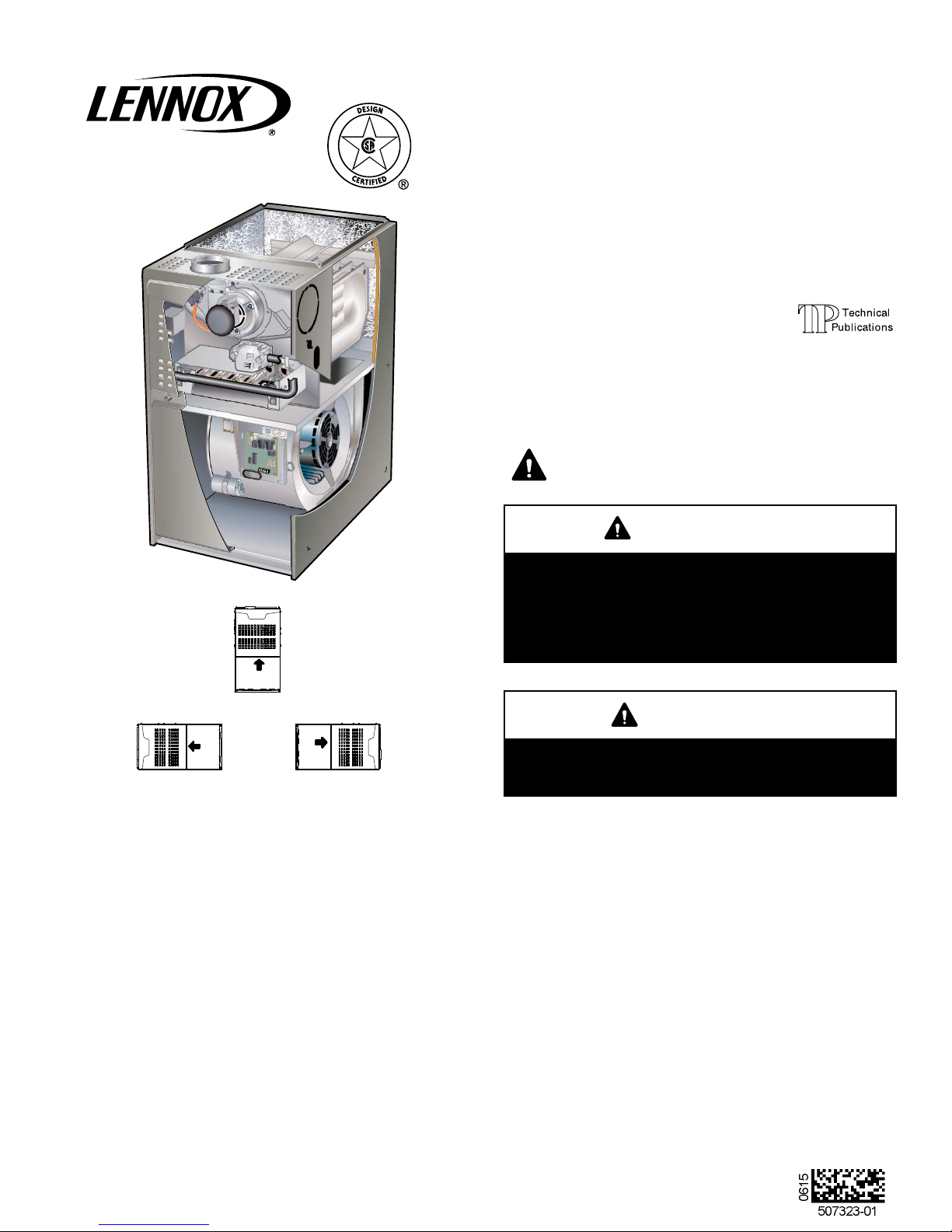
ML180UH
MERIT® SERIES GAS FURNACE
UPFLOW / HORIZONTAL AIR DISCHARGE
507323-01
06/2015
Supersedes 507009-01
Litho U.S.A.
THIS MANUAL MUST BE LEFT WITH THE
HOMEOWNER FOR FUTURE REFERENCE
This is a safety alert symbol and should never be ignored.
When you see this symbol on labels or in manuals, be alert
to the potential for personal injury or death.
WARNING
Improper installation, adjustment, alteration, service
or maintenance can cause property damage, person
al injury or loss of life. Installation and service must
be performed by a licensed professional HVAC in
staller (or equivalent), service agency or the gas sup
plier.
AIR FLOW
AIR FLOW
HORIZONTAL LEFT
UPFLOW
AIR FLOW
HORIZONTAL RIGHT
Table of Contents
Unit Dimensions 2................................
ML180UH Gas Furnace 3..........................
Shipping and Packing List 3........................
Safety Information 3...............................
Use of Furnace as a Construction Heater 4...........
General 4........................................
Combustion, Dilution & Ventilation Air 5..............
Setting Equipment 8...............................
Filters 11..........................................
Duct System 12....................................
Venting 13........................................
CAUTION
As with any mechanical equipment, personal injury
can result from contact with sharp sheet metal
edges. Be careful when you handle this equipment.
Gas Piping 20.....................................
Electrical 22.......................................
Integrated Control 24...............................
Unit Start-Up 26...................................
Gas Pressure Adjustment 26........................
High Altitude 26....................................
Proper Combustion 26..............................
Other Unit Adjustments 28..........................
Twinning the ML180UH 29..........................
Service 30........................................
Repair Parts 32....................................
Page 1
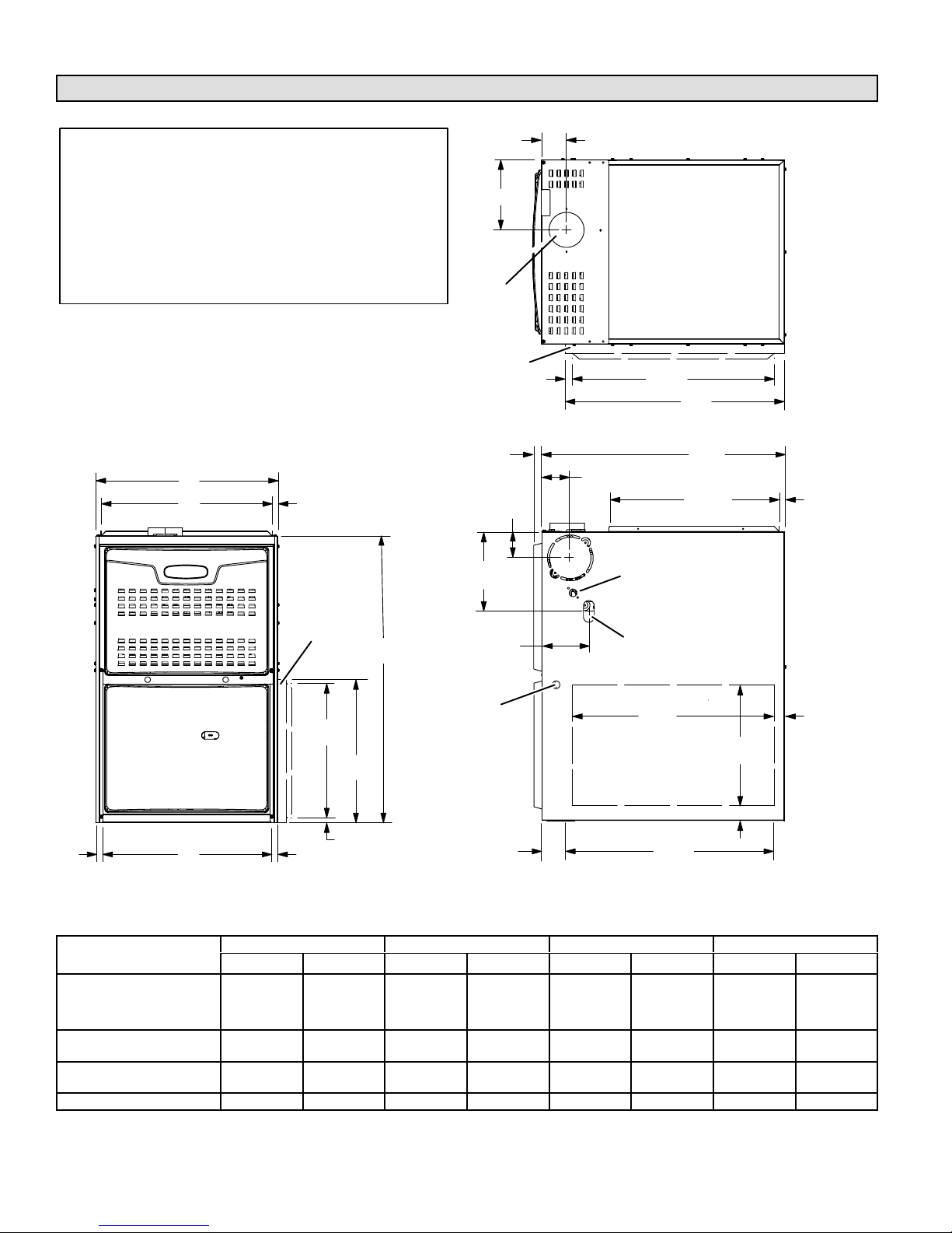
Unit Dimensions - inches (mm)
1
NOTE - 60C and 60D units that require air volumes
over 1800 cfm (850 L/s) must have one of the following:
1. Single side return air with transition to accommodate
20 x 25 x 1 in. (508 x 635 x 25 mm) cleanable air
filter. (Required to maintain proper air velocity.)
2. Single side return with optional return air base.
3. Bottom return air.
4. Return air from both sides.
5. Bottom and one side return air.
See Blower Performance Tables for additional informa
tion.
2
Flue outlet may be horizontal but furnace must be
vented vertically
3
Optional external side return air filter kit cannot be used
with the optional RAB Return Air Base.
A
B
9/16 (14)
3
OPTIONAL
EXTERNAL
SIDE RETURN
AIR FILTER KIT
(Either Side)
33
(838)
D
FLUE OUTLET
(Top)
3
OPTIONAL
EXTERNAL
SIDE RETURN
AIR FILTER KIT
(Either Side)
3/4(19)
Front Panel
3 (76) Right
6−3/4 (171) Left
9−1/8 (232) Right
8−5/8 (219) Left
5−3/8 (137) Right
1−9/16 (40) Left
3−1/8 (79)
TOP VIEW
3−1/4 (83)
2
FLUE OUTLET
(Either Side)
ELECTRICAL INLET
(Either Side)
GAS PIPING INLET
(Either Side)
SUPPLY AIR
OPENING
23−3/4
(603)
25
(635)
27−3/4
(705)
19−7/16
(494)
9/16
(14)
3/4
(19)
FRONT VIEW
ML180UH Model No.
045P24A
045P36A
070P24A
070P36A
090P36B
090P48B
110P48C
110P60C
135P60D
C
1
Bottom Return
Air Opening
3/4
(19)
14−3/4
(375)
(16)
(406)
5/8
16
ELECTRICAL
INLET (Either Side)
(Either Side)
3−1/4
(83)
23
(584)
1
Side Return
Air Opening
(Either Side)
23−1/2
(597)
1
Bottom Return
Air Opening
14
(356)
1−15/16 (49)
1−1/2
(38)
SIDE VIEW
A B C D
in. mm in. mm in. mm in. mm
14-1/2 368 13-3/8 340 13 330 4-3/4 121
17-1/2 446 16-3/8 416 16 406 6-1/4 159
21 533 19-7/8 504 19-1/2 495 8 203
24-1/2 622 23-3/8 546 23 584 9-3/4 248
Page 2
ML180UH Gas Furnace
The ML180UH unit is shipped ready for installation in the
upflow or horizontal right position (for horizontal left posi
tion the combustion air pressure switch must be moved).
The furnace is shipped with the bottom panel in place. The
bottom panel must be removed if the unit is to be installed in
a horizontal application. The panel may also be removed in
upflow applications.
Shipping and Packing List
Package 1 of 1 contains
1 - Assembled ML180UH unit
1 - Bag assembly containing the following:
2 - Screws
1 - Snap bushing
1 - Snap plug
1 - Wire tie
1 - Vent warning label
1 - Owner's manual and warranty card
The following items may be ordered separately:
1 - Thermostat
1 - Suspension kit (for horizontal installations)
1 - Propane/LP changeover kit
1 - Return air base
1 - High altitude kit
1 - Side filter kit
Check equipment for shipping damage. If you find any
damage, immediately contact the last carrier.
Safety Information
DANGER
Danger of explosion.
There are circumstances in which odorant used with
LP/propane gas can lose its scent. In case of a leak,
LP/propane gas will settle close to the floor and may
be difficult to smell. An LP/propane leak detector
should be installed in all LP applications.
WARNING
Improper installation, adjustment, alteration, service
or maintenance can cause property damage, person
al injury or loss of life. Installation and service must
be performed by a licensed professional installer (or
equivalent), service agency or the gas supplier.
CAUTION
As with any mechanical equipment, personal injury
can result from contact with sharp sheet metal
edges. Be careful when you handle this equipment.
Certifications
ML180UH units are CSA International certified to ANSI
Z21.47.
In the USA, installation of gas furnaces must conform with
local building codes. In the absence of local codes, units
must be installed according to the current National Fuel
Gas Code (ANSI‐Z223.1). The National Fuel Gas Code is
available from the following address:
American National Standards Institute, Inc.
11 West 42nd Street
New York, NY 10036
Clearances
Adequate clearance must be made around the air open
ings into the vestibule area. In order to ensure proper unit
operation, combustion and ventilation air supply must be
provided according to the current National Fuel Gas Code.
Vent installations must be consistent with the venting
tables (in this instruction) and applicable provisions of local
building codes.
This furnace is CSA International certified for installation
clearances to combustible material as listed on the unit
nameplate and in the tables in figures 7 and 11. Accessibil
ity and service clearances must take precedence over fire
protection clearances.
NOTE - For installation on combustible floors, the furnace
shall not be installed directly on carpeting, tile, or other
combustible material other than wood flooring.
Installed Locations
For installation in a residential garage, the furnace must be
installed so that the burner(s) and the ignition source are
located no less than 18 inches (457 mm) above the floor.
The furnace must be located or protected to avoid physical
damage by vehicles. When a furnace is installed in a public
garage, hangar, or other building that has a hazardous at
mosphere, the furnace must be installed according to rec
ommended good practice requirements and current Na
tional Fuel Gas Code.
Temperature Rise
NOTE - Furnace must be adjusted to obtain a temperature
rise within the range specified on the unit nameplate. Fail
ure to do so may cause erratic limit operation and may re
sult in premature heat exchanger failure.
This ML180UH furnace must be installed so that its electri
cal components are protected from water.
Page 3
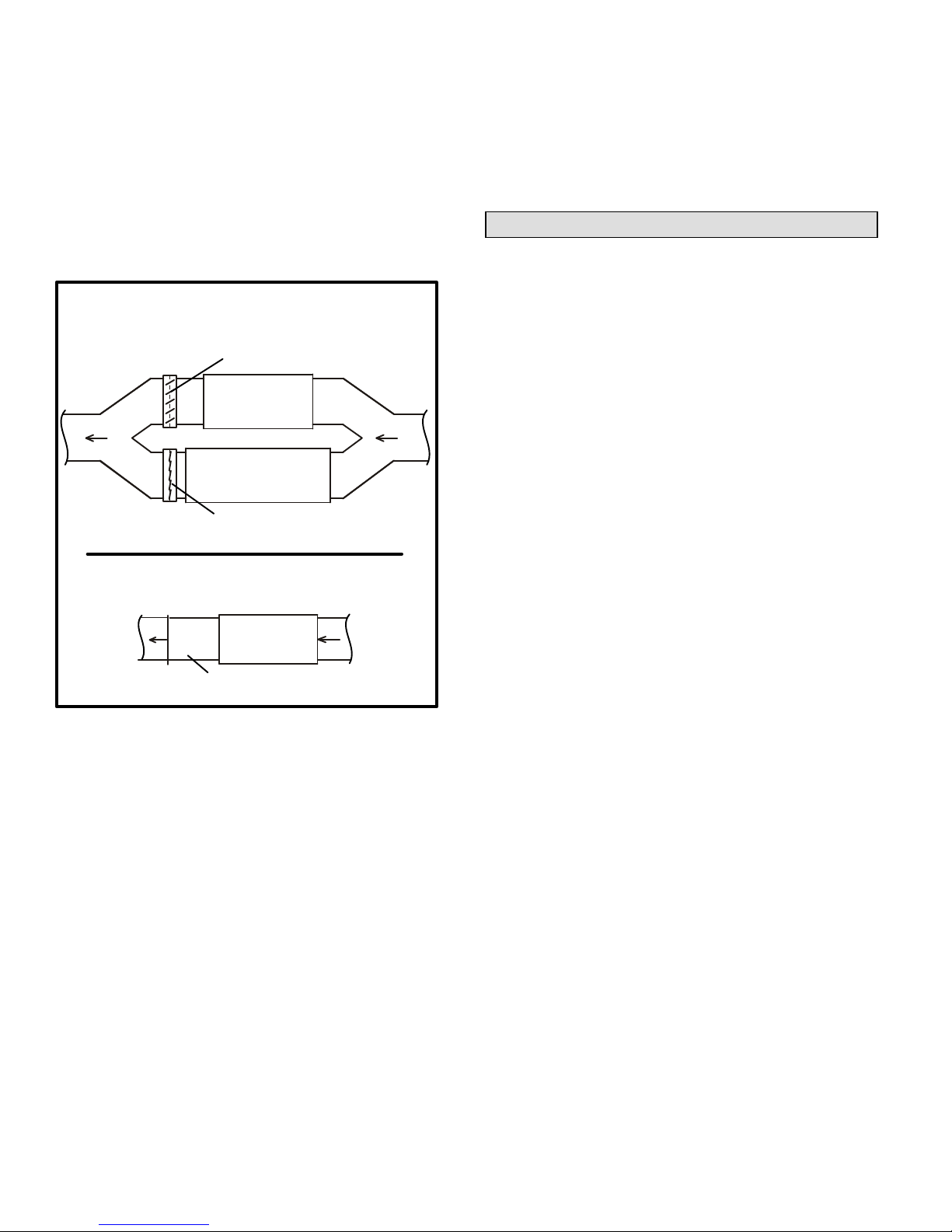
Installed in Combination with a Cooling Coil
When this furnace is used with cooling units, it shall be
installed in parallel with, or on the upstream side of, cooling
units to avoid condensation in the heating compartment.
See figure 1. With a parallel flow arrangement, a damper
(or other means to control the flow of air) must adequately
prevent chilled air from entering the furnace. If the damper
is manually operated, it must be equipped to prevent op
eration of either the heating or the cooling unit, unless it is in
the full HEAT or COOL setting. See figure 1.
Heating Unit Installed Parallel to Cooling Coil
Dampers
(open during heating operation only)
Gas Unit
Cooling Coil
Dampers
(open during cooling operation only)
Heating Unit Installed Upstream of Cooling Unit
The ML180UH furnace may be installed in alcoves, clos
ets, attics, basements, garages, crawl spaces and utility
rooms in the upflow or horizontal position.
This furnace design has not been CSA International
certified for installation in mobile homes, recreational
vehicles, or outdoors.
Use of Furnace as Construction Heater
Lennox does not recommend the use of ML180UH units as
a construction heater during any phase of construction.
Very low return air temperatures, harmful vapors and op
eration of the unit with clogged or misplaced filters will dam
age the unit.
ML180UH units may be used for heating of buildings or
structures under construction, if the following conditions
are met:
D The vent system must be permanently installed per
these installation instructions.
D A room thermostat must control the furnace. The use of
fixed jumpers that will provide continuous heating is not
allowed.
D The return air duct must be provided and sealed to the
furnace.
D Return air temperature range between 60°F (16°C) and
80°F (27°C) must be maintained.
Gas Unit
Cooling Coil
FIGURE 1
When installed, this furnace must be electrically grounded
according to local codes. In addition, in the United States,
installation must conform with the current National Electric
Code, ANSI/NFPA No. 70. The National Electric Code
(ANSI/NFPA No. 70) is available from the following ad
dress:
National Fire Protection Association
1 Battery March Park
Quincy, MA 02269
NOTE - This furnace is designed for a minimum continuous
return air temperature of 60°F (16°C) or an intermittent op
eration down to 55°F (13°C) dry bulb for cases where a
night setback thermostat is used. Return air temperature
must not exceed 85°F (29°C) dry bulb.
D Air filters must be installed in the system and must be
maintained during construction.
D Air filters must be replaced upon construction comple
tion.
D The input rate and temperature rise must be set per the
furnace rating plate.
D One hundred percent (100%) outdoor air must be pro
vided for combustion air requirements during construc
tion. Temporary ducting may supply outdoor air to the
furnace. Do not connect duct directly to the furnace.
Size the temporary duct following these instructions in
section for Combustion, Dilution and Ventilation Air in a
confined space with air from outside.
D The furnace heat exchanger, components, duct sys
tem, air filters and evaporator coils must be thoroughly
cleaned following final construction clean-up.
D All furnace operating conditions (including ignition, in
put rate, temperature rise and venting) must be verified
according to these installation instructions.
Page 4
General
These instructions are intended as a general guide and do
not supersede local codes in any way. Consult authorities
having jurisdiction before installation.
In addition to the requirements outlined previously, the fol
lowing general recommendations must be considered
when installing a ML180UH furnace:
Place the furnace as close to the center of the air dis
tribution system as possible. The furnace should also be
located close to the chimney or vent termination point.
Do not install the furnace where drafts might blow direct
ly into it. This could cause improper combustion and un
safe operation.
Do not block the furnace combustion air openings with
clothing, boxes, doors, etc. Air is needed for proper
combustion and safe unit operation.
When the furnace is installed in an attic or other insu
lated space, keep insulation away from the furnace.
• Please consult the manufacturer of your evaporator coil
for their recommendations on distance required
between the heat exchanger and their drain pan. Ad
equate space must be provided between the drain pan
and the furnace heat exchanger.
NOTE - The Commonwealth of Massachusetts stipu
lates these additional requirements:
D Gas furnaces shall be installed by a licensed plumb
er or fitter only.
D The gas cock must be “T handle” type.
D When a furnace is installed in an attic, the passage
way to and service area surrounding the equipment
shall be floored.
WARNING
The State of California has determined that this prod
uct may contain or produce a chemical or chemicals,
in very low doses, which may cause serious illness
or death. It may also cause cancer, birth defects or
reproductive harm.
will build to the point that a downdraft can occur in the fur
nace vent pipe or chimney. As a result, combustion gases
enter the living space creating a potentially dangerous situ
ation.
In the absence of local codes concerning air for combus
tion and ventilation, use the guidelines and procedures in
this section to install ML180UH furnaces to ensure efficient
and safe operation. You must consider combustion air
needs and requirements for exhaust vents and gas piping.
A portion of this information has been reprinted with per
mission from the National Fuel Gas Code (ANSI‐Z223.1).
This reprinted material is not the complete and official posi
tion of the ANSI on the referenced subject, which is repre
sented only by the standard in its entirety.
CAUTION
Do not install the furnace in a corrosive or contami
nated atmosphere. Meet all combustion and ventila
tion air requirements, as well as all local codes.
CAUTION
Insufficient combustion air can cause headaches,
nausea, dizziness or asphyxiation. It will also cause
excess water in the heat exchanger resulting in rust
ing and premature heat exchanger failure. Excessive
exposure to contaminated combustion air will result
in safety and performance related problems. Avoid
exposure to the following substances in the com
bustion air supply:
Permanent wave solutions
Chlorinated waxes and cleaners
Chlorine base swimming pool chemicals
Water softening chemicals
De‐icing salts or chemicals
Carbon tetrachloride
Halogen type refrigerants
Cleaning solvents (such as perchloroethylene)
Printing inks, paint removers, varnishes, etc.
Hydrochloric acid
Cements and glues
Antistatic fabric softeners for clothes dryers
Masonry acid washing materials
Combustion, Dilution & Ventilation Air
In the past, there was no problem in bringing in sufficient
outdoor air for combustion. Infiltration provided all the air
that was needed. In today's homes, tight construction prac
tices make it necessary to bring in air from outside for com
bustion. Take into account that exhaust fans, appliance
vents, chimneys, and fireplaces force additional air that
could be used for combustion out of the house. Unless out
side air is brought into the house for combustion, negative
pressure (outside pressure is greater than inside pressure)
All gas‐fired appliances require air for the combustion pro
cess. If sufficient combustion air is not available, the fur
nace or other appliances will operate inefficiently and un
safely. Enough air must be provided to meet the needs of
all fuel‐burning appliances and appliances such as ex
haust fans which force air out of the house. When fire
places, exhaust fans, or clothes dryers are used at the
same time as the furnace, much more air is necessary to
ensure proper combustion and to prevent a downdraft. In
sufficient air causes incomplete combustion which can re
sult in carbon monoxide.
Page 5
In addition to providing combustion air, fresh outdoor air di
lutes contaminants in the indoor air. These contaminants
may include bleaches, adhesives, detergents, solvents
and other contaminants which can corrode furnace compo
nents.
The requirements for providing air for combustion and ven
tilation depend largely on whether the furnace is installed in
an unconfined or a confined space.
Unconfined Space
An unconfined space is an area such as a basement or
large equipment room with a volume greater than 50 cubic
feet (1.42 m
3
) per 1,000 Btu (.29 kW) per hour of the com
bined input rating of all appliances installed in that space.
This space also includes adjacent rooms which are not
separated by a door. Though an area may appear to be un
confined, it might be necessary to bring in outdoor air for
combustion if the structure does not provide enough air by
infiltration. If the furnace is located in a building of tight
construction with weather stripping and caulking around
the windows and doors, follow the procedures in the air
from outside section.
Confined Space
A confined space is an area with a volume less than 50 cu
bic feet (1.42 m
3
) per 1,000 Btu (.29 kW) per hour of the
combined input rating of all appliances installed in that
space. This definition includes furnace closets or small
equipment rooms.
When the furnace is installed so that supply ducts carry air
circulated by the furnace to areas outside the space con
taining the furnace, the return air must be handled by ducts
which are sealed to the furnace casing and which terminate
outside the space containing the furnace. This is especially
important when the furnace is mounted on a platform in a
confined space such as a closet or small equipment room.
Even a small leak around the base of the unit at the platform
or at the return air duct connection can cause a potentially
dangerous negative pressure condition. Air for combustion
and ventilation can be brought into the confined space ei
ther from inside the building or from outside.
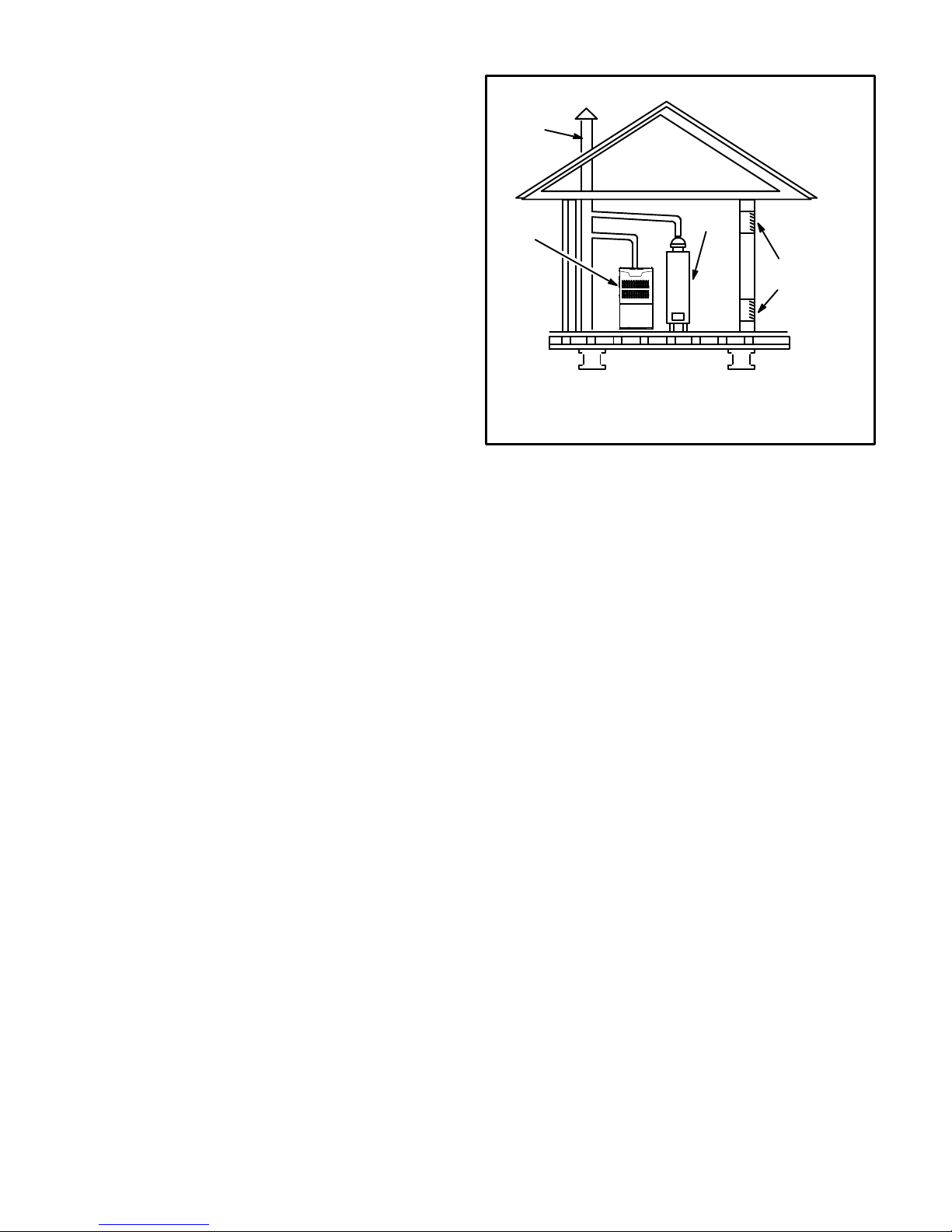
EQUIPMENT IN CONFINED
SPACE ALL AIR FROM INSIDE
CHIMNEY
OR GAS
VENT
WATER
FURNACE
NOTE - Each opening shall have a free area of at least one square
inch (645 mm
ing of all equipment in the enclosure, but not less than 100 square
inches (64516 mm
2
) per 1,000 Btu (.29 kW) per hour of the total input rat
2
).
HEATER
OPENINGS
(To Adjacent
Room)
FIGURE 2
Air from Inside
If the confined space that houses the furnace adjoins a
space categorized as unconfined, air can be brought in by
providing two permanent openings between the two
spaces. Each opening must have a minimum free area of 1
square inch (645 mm
2
) per 1,000 Btu (.29 kW) per hour of
total input rating of all gas-fired equipment in the confined
space. Each opening must be at least 100 square inches
(64516 mm
2
). One opening shall be within 12 inches (305
mm) of the top of the enclosure and one opening within 12
inches (305 mm) of the bottom. See figure 2.
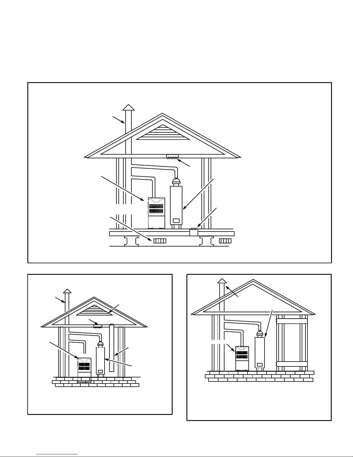
Air from Outside
If air from outside is brought in for combustion and ventila
tion, the confined space must have two permanent open
ings. One opening shall be within 12 inches (305 mm) of the
top of the enclosure and one opening within 12 inches (305
mm) of the bottom. These openings must communicate di
rectly or by ducts with the outdoors or spaces (crawl or at
tic) that freely communicate with the outdoors or indirectly
through vertical ducts. Each opening shall have a minimum
free area of 1 square inch (645 mm
2
) per 4,000 Btu (1.17
kW) per hour of total input rating of all equipment in the en
closure. See figures 3 and 4. When communicating with
the outdoors through horizontal ducts, each opening shall
have a minimum free area of 1 square inch (645 mm
2
) per
2,000 Btu (.56 kW) per total input rating of all equipment in
the enclosure. See figure 5.
Page 6
When ducts are used, they shall be of the same cross-sec
tional area as the free area of the openings to which they
connect. The minimum dimension of rectangular air ducts
shall be no less than 3 inches (75 mm). In calculating free
area, the blocking effect of louvers, grilles, or screens must
be considered. If the design and free area of protective cov
ering is not known for calculating the size opening required,
(Inlet Air from Crawlspace and Outlet Air to Ventilated Attic)
CHIMNEY OR
GAS VENT
VENTILATION LOUVERS
(Each end of attic)
FURNACE
it may be assumed that wood louvers will have 20 to 25 per
cent free area and metal louvers and grilles will have 60 to
75 percent free area. Louvers and grilles must be fixed in
the open position or interlocked with the equipment so that
they are opened automatically during equipment opera
tion.
EQUIPMENT IN CONFINED SPACE
ALL AIR FROM OUTSIDE
OUTLET
AIR
WATER
HEATER
CHIMNEY
OR GAS
VENT
FURNACE
VENTILATION
LOUVERS
(For unheated crawl space)
NOTE-The inlet and outlet air openings shall each have a free area of at least one square inch (645
2
mm
) per 4,000 Btu (1.17 kW) per hour of the total input rating of all equipment in the enclosure.
INLET
AIR
FIGURE 3
EQUIPMENT IN CONFINED SPACE
ALL AIR FROM OUTSIDE
(All Air Through Ventilated Attic)
CHIMNEY
OR GAS
VENT
OUTLET
AIR
VENTILATION LOUVERS
(Each end of attic)
INLET AIR
(Ends 12 in.
above bottom)
WATER
HEATER
FURNACE
WATER
HEATER
EQUIPMENT IN
CONFINED SPACE
ALL AIR FROM
OUTSIDE
OUTLET AIR
INLET AIR
NOTE-The inlet and outlet air openings shall each have a
free area of at least one square inch (645 mm
Btu (1.17 kW) per hour of the total input rating of all equip
ment in the enclosure.
FIGURE 4
2
) per 4,000
Page 7
NOTE - Each air duct opening shall have a free area of at least one
square inch (645 mm
2
) per 2,000 Btu (.59 kW) per hour of the total
input rating of all equipment in the enclosure. If the equipment room
is located against an outside wall and the air openings communi
cate directly with the outdoors, each opening shall have a free area
of at least one square inch (645 mm
2
) per 4,000 Btu (1.17 kW) per
hour of the total input rating of all other equipment in the enclosure.
FIGURE 5

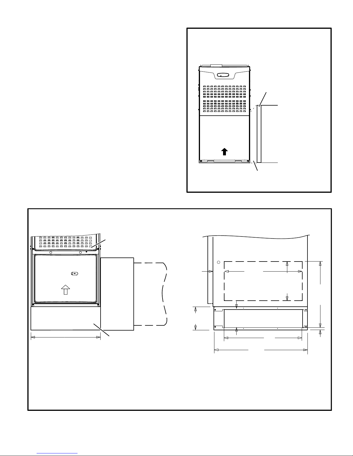
Setting Equipment
WARNING
Do not install the furnace on its front or its back. Do
not connect the return air ducts to the back of the fur
nace. Doing so will adversely affect the operation of
the safety control devices, which could result in per
sonal injury or death.
NOTE - As an option, rubberlike pads defined as having an
elastic texture resembling rubber in flexibility or toughness,
may be placed under each corner of the furnace as ap
propriate to the application.
The ML180UH gas furnace can be installed as shipped in
either the upflow position or the horizontal position.
Select a location that allows for the required clearances
that are listed on the unit nameplate. Also consider gas
supply connections, electrical supply, vent connection, and
installation and service clearances [24 inches (610 mm) at
unit front]. The unit must be level.
NOTE - Units with 1/2 hp blower motors are equipped with
three flexible legs and one rigid leg. See figure 6. The rigid
leg is equipped with a shipping bolt and a flat white plastic
washer (rather than the rubber mounting grommet used
with a flexible mounting leg). The bolt and washer must
be removed before the furnace is placed into opera
tion. After the bolt and washer have been removed, the rig
id leg will not touch the blower housing.
ML180UH09048B with 1/2 HP
BLOWER MOTOR
RIGID LEG
remove shipping bolt and washer
Upflow Applications
Allow for clearances to combustible materials as indicated
on the unit nameplate. Minimum clearances for closet or al
cove installations are shown in figure 7.
Upflow Application Installation Clearances
Top
Left Side
Bottom
Type of Vent
Connector
Top 1 in. (25 mm) 1 in. (25 mm)
*Front 2-1/4 in. (57 mm)** 2-1/4 in. (57 mm)
Back 0 0
Sides 0† 0
Vent 6 in. (152 mm) 1 in. (25 mm)
Floor 0‡ 0‡
*Front clearance in alcove installation must be 24 in. (610 mm).
Maintain a minimum of 24 in. (610 mm) for front service access.
** 4-1/2 in. if single wall vent pipe is used.
‡For installation on a combustible floor, do not install the furnace
directly on carpeting, tile or other combustible materials other
than wood flooring.
†Left side requires 3 inches if a single wall vent is used on 14-1/2
in. cabinets, or 2inches if a single wall vent pipe is used on 17-1/2
in. cabinets.
Type C Type B1
Right Side
FIGURE 7
FIGURE 6
Page 8
Return Air -- Upflow Applications
Return air can be brought in through the bottom or either
side of the furnace installed in an upflow application. If the
furnace is installed on a platform with bottom return, make
an airtight seal between the bottom of the furnace and the
platform to ensure that the furnace operates properly and
safely. The furnace is equipped with a removable bottom
panel to facilitate installation.
Markings are provided on both sides of the furnace cabinet
for installations that require side return air. Cut the furnace
cabinet at the maximum dimensions shown on page 2.
Single Side Return Air
(with transition and filter)
20” X 25” X 1”
(508mm X 635mm X 25mm)
Cleanable Filter
NOTE -
60C and 60D units that require air volumes over 1800
cfm (850 L/s) must have one of the following:
1 - Single side return air with transition to accommodate 20
x 25 x 1 in. (508 x 635 x 25 mm) cleanable air filter. (Re
quired to maintain proper air velocity.) See figure 8.
2 - Single side return air with optional return airbase. See
figure 9.
3 - Bottom return air.
4 - Return air from both sides.
5 - Bottom and one side return air.
Refer to Engineering Handbook for additional information.
Optional Return Air Base
(Upflow Applications Only -- For use with A, B, C and D cabinets)
FURNACE
FRONT
IF BASE
IS USED
WITHOUT
IAQ CABINET,
A SINGLE
RETURN AIR
PLENUM
MUST
COVER BOTH
UNIT AND
RETURN
AIR BASE
OPENINGS
AIR FLOW
INDOOR AIR
QUALITY
CABINET
(PCO, Filter
Cabinet, etc.)
3−1/4
(83)
7−1/4
(184)
AIR FLOW
1
Unit side return air
5−5/8
(143)
Return Air
Transition
FIGURE 8
1
23 (584)
Overall
(Maximum)
Opening
SIDE RETURN
AIR OPENINGS
(Either Side)
Plenum
1
Minimum
11 (279)
2
Maximum
14 (356)
1
22−7/16
(570)
Overall
(Maximum)
14−1/2 (368) A Width (65W75)
17−1/2 (446) B Width (50W98)
21 (533) C Width (50W99)
24−1/2 (622) D Width (51W00)
NOTE- Optional Side Return Air Filter Kits are not for use with Optional Return Air Base.
1
Both the unit return air opening and the base return air opening must be covered by a single plenum or IAQ cabinet.
OPTIONAL
RETURN
AIR BASE
Minimum unit side return air opening dimensions for units requiring 1800 cfm or more of air (W x H): 23 x 11 in. (584 x 279 mm).
The opening can be cut as needed to accommodate plenum or IAQ cabinet while maintaining dimensions shown.
Side return air openings must be cut in the field. There are cutting guides stenciled on the cabinet for the side return air
opening. The size of the opening must not extend beyond the markings on the furnace cabinet.
2
To minimize pressure drop, the largest opening height possible (up to 14 inches 356 mm) is preferred.
FIGURE 9
Page 9
23
(584)
26−7/8
(683)
SIDE VIEW
3/4
(19)
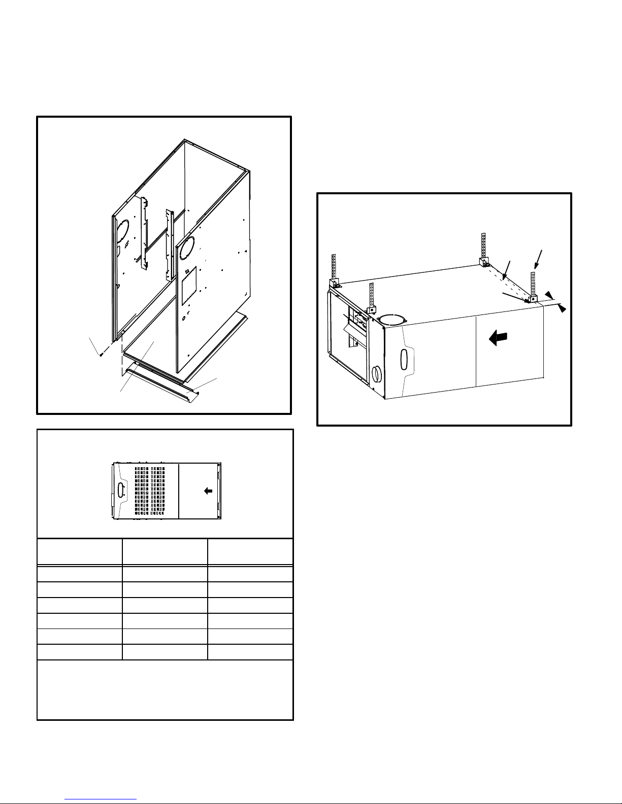
Removing the Bottom Panel
Remove the two screws that secure the bottom cap to the
furnace. Pivot the bottom cap down to release the bottom
panel. Once the bottom panel has been removed, reinstall
the bottom cap. See figure 10.
Removing the Bottom Panel
Horizontal Applications
The ML180UH furnace can be installed in horizontal ap
plications. Order horizontal suspension kit (51W10) from
Lennox, or use equivalent suspension method.
Allow for clearances to combustible materials as indicated
on the unit nameplate. Minimum clearances for closet or al
cove installations are shown in figure 11.
This furnace may be installed in either an attic or a crawl
space. Either suspend the furnace from roof rafters or floor
joists, as shown in figure 12, or install the furnace on a plat
form, as shown in figure 13.
Typical Horizontal Application
Unit Suspended in Attic or Crawlspace
Metal
Internal
Strap
Brace
Screw
Bottom Cap
Bottom Panel
FIGURE 10
Horizontal Application
Installation Clearances
Left
End
Vent Connector
Type
Top 0 0
*Front 2-1/4 in. (57 mm)** 2-1/4 in. (57 mm)
Back 0 0
Ends 2 in. (51 mm) 2 in. (51 mm)
Vent 6 in. (152 mm) 1 in. (25 mm)
Floor 0‡ 0‡
*Front clearance in alcove installation must be 24 in. (610 mm).
Maintain a minimum of 24 in. (610 mm) for front service access.
** 4-1/2 in. if singlewall vent pipe is used.
‡For installations on a combustible floor, do not install the fur
nace directly on carpeting, tile or other combustible materials oth
er than wood flooring.
Top
Right
AIR FLOW
End
Bottom
Type C Type B1
Bracket
3/16
Air Flow
FIGURE 12
NOTE - Heavy-gauge perforated sheet metal straps may
be used to suspend the unit from roof rafters or ceiling
joists. When straps are used to suspend the unit in this way,
support must be provided for both the ends. The straps
must not interfere with the plenum or exhaust piping instal
lation. Cooling coils and supply and return air plenums
must be supported separately.
NOTE - When the furnace is installed on a platform in a
crawlspace, it must be elevated enough to avoid water
damage and to allow the evaporator coil to drain.
Return Air -- Horizontal Applications
Return air must be brought in through the end of a furnace
installed in a horizontal application. The furnace is
equipped with a removable bottom panel to facilitate instal
lation. See figure 10.
FIGURE 11
Page 10
 Loading...