

Lennox ML180DF045P36A, ML180DF070P36A, ML180DF090P48B, ML180DF090XP48B, ML180DF110P60C Unit Information
...Page 1
Corp. 1219-L4
Service Literature
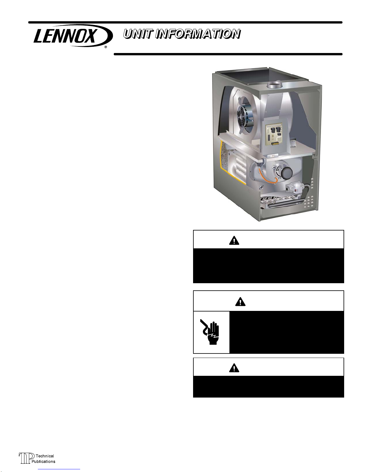
ML180DF series units are mid-efficiency gas furnaces
used for downflow applications only, manufactured with
Lennox Duralokt heat exchangers formed of aluminized
steel. ML180DF units are available in heating capacities of
44,000 to 110,000 Btuh and cooling applications 1.5 to 5
tons. Refer to Product Specifications bulletin for proper siz
ing.
Units are factory equipped for use with natural gas. Kits are
available for conversion to LP/Propane operation.
ML180DF model units are equipped with a hot surface igni
tion system. All units use a redundant gas valve to assure
safety shut-off as required by C.S.A.
All specifications in this manual are subject to change. Pro
cedures outlined in this manual are presented as a recom
mendation only and do not supersede or replace local or
state codes. In the absence of local or state codes, the
guidelines and procedures outlined in this manual (except
where noted) are recommended only and do not constitute
code.
TABLE OF CONTENTS
Specifications Page 2.............................
Blower Data Page 4..............................
Parts Identification Page 5.........................
I Unit Components Page 6........................
II Installation Page 14.............................
III Start Up Page 14..............................
IV Heating System Service Checks Page 14.........
Revised 02/2013
ML180DF(X)
IMPORTANT
Improper installation, adjustment, alteration, service
or maintenance can cause property damage, person
al injury or loss of life. Installation and service must
be performed by a qualified installer, service agency
or the gas supplier.
WARNING
Electric shock hazard. Can cause injury
or death. Before attempting to perform
any service or maintenance, turn the
electrical power to unit OFF at discon
nect switch(es). Unit may have multiple
power supplies.
V Typical Operating Characteristics Page 19.........
VI Maintenance Page 19..........................
VII Wiring and Sequence of Operation Page 22......
VIII Twinning Page 27.............................
Page 1
WARNING
Sharp edges.
Be careful when servicing unit to avoid sharp edges
which may result in personal injury.
© 2013 Lennox Industries Inc.
Page 2
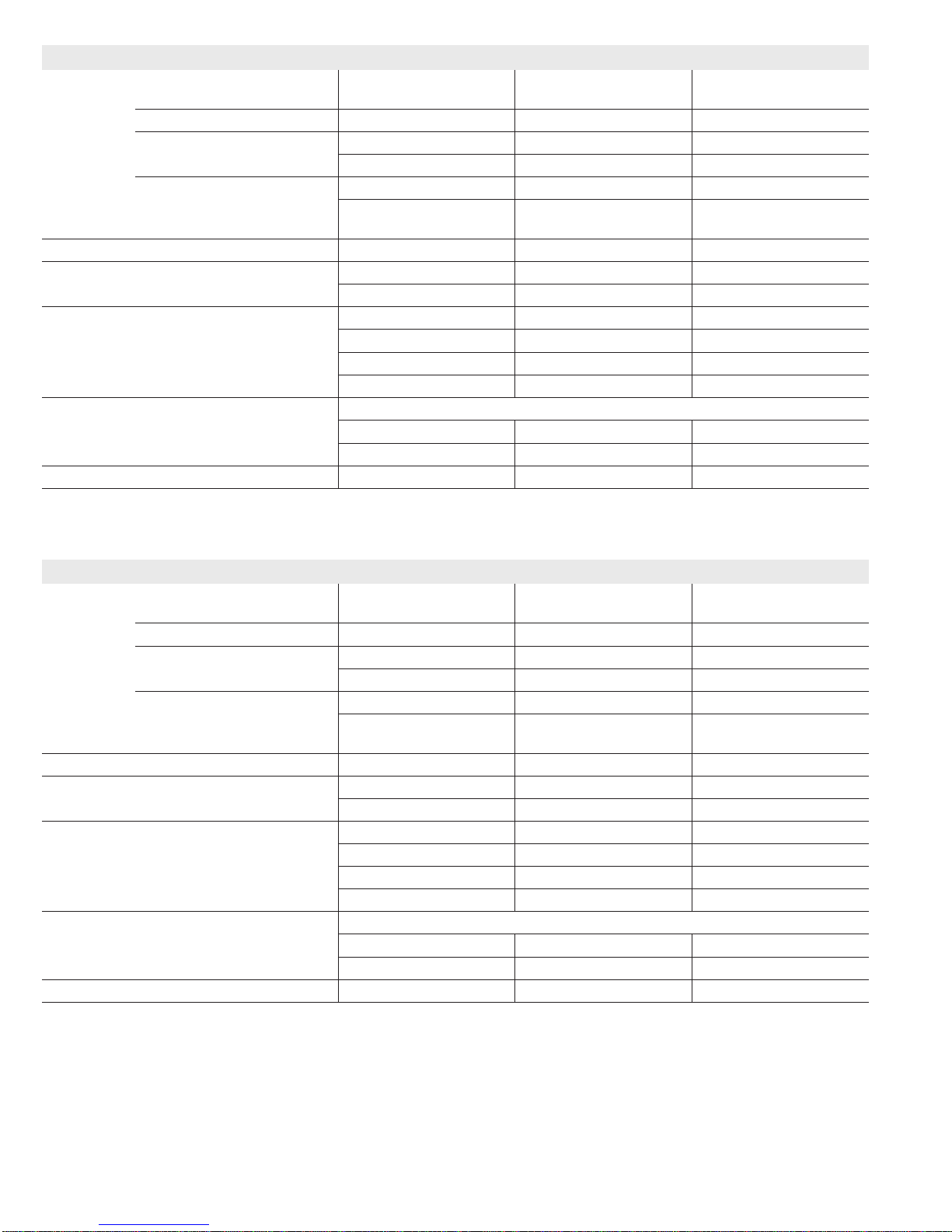
SPECIFICATIONS
Gas
Heating
Model No. - Low NO
Performance
Temperature rise range - °F 25 - 55 15 - 45 25 - 55
Gas Manifold Pressure (in. w.g.)
Nat. Gas / LPG/Propane
High Static - in. w.g. 0.50 0.50 0.50
Connections
Flue connection - in. round 4 4 4
in.
Indoor
Wheel nom. dia. x width - in. 10 x 7 10 x 8 10 x 8
Blower
Tons of add-on cooling 1.5 - 2 2 - 3 2 - 3
Air Volume Range - cfm 401 - 1157 739 - 1524 717 - 1562
Electrical
Data
Blower motor full load amps 3.1 6.1 6.1
Maximum overcurrent protection 15 15 15
Shipping Data lbs. - 1 package 105 113 128
NOTE - Filters and provisions for mounting are not furnished and must be eld provided.
1
Annual Fuel Utilization Efciency based on DOE test procedures and according to FTC labeling regulations. Isolated combustion system rating for non-weatherized furnaces.
Model No.
1
AFUE 80% 80% 80%
ML180DF045P24A
x
- - -
ML180DF045P36A
- - -
ML180DF070P36A
ML180DF070XP36A
Input - Btuh 44,000 44,000 66,000
Output - Btuh 35,000 36,000 53,000
3.5 / 10.0 3.5 / 10.0 3.5 / 10.0
Gas pipe size IPS 1/2 1/2 1/2
Motor output - hp 1/5 1/3 1/3
Voltage 120 volts - 60 hertz - 1 phase
SPECIFICATIONS
Gas
Heating
Model No. - Low NO
Performance
Temperature rise range - °F 35 - 65 25 - 55 30 - 60
Gas Manifold Pressure (in. w.g.)
Nat. Gas / LPG/Propane
High Static - in. w.g. 0.50 0.50 0.50
Connections
Flue connection - in. round 4 4 4
in.
Indoor
Wheel nom. dia. x width - in. 10 x 9 10 x 10 11-1/2 x 10
Blower
Tons of add-on cooling 2 - 3 3 - 4 4 - 5
Air Volume Range - cfm 743 -1695 917 - 1929 1517 - 2760
Electrical
Data
Blower motor full load amps 6.1 8.2 10.0
Maximum overcurrent protection 15 15 15
Shipping Data lbs. - 1 package 131 140 160
NOTE - Filters and provisions for mounting are not furnished and must be eld provided.
1
Annual Fuel Utilization Efciency based on DOE test procedures and according to FTC labeling regulations. Isolated combustion system rating for non-weatherized furnaces.
Model No.
1
AFUE 80% 80% 80%
ML180DF090P36B
x
- - -
ML180DF090P48B
ML180DF090XP48B
ML180DF110P60C
ML180DF110XP60C
Input - Btuh 88,000 88,000 110,000
Output - Btuh 71,000 71,000 89,000
3.5 / 10.0 3.5 / 10.0 3.5 / 10.0
Gas pipe size IPS 1/2 1/2 1/2
Motor output - hp 1/3 1/2 1
Voltage 120 volts - 60 hertz - 1 phase
Page 2
Page 3
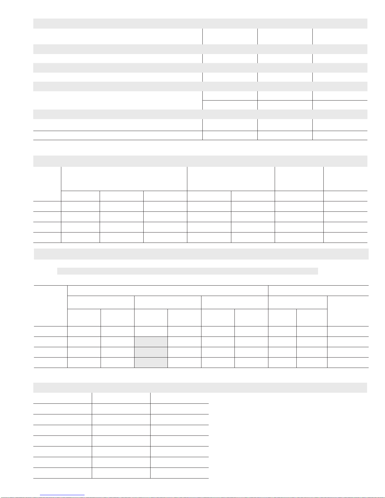
OPTIONAL ACCESSORIES - ORDER SEPARATELY
“A” Width
Models
CABINET ACCESSORIES
Downow Combustible Flooring Base 11M59 11M60 11M61
CONTROLS
Twinning Kit 15L38 15L38 15L38
FILTERS
1
Downow Filter Cabinet 51W06 51W07 51W08
No. and Size of lter - in. (1) 20 x 20 x 1 (2) 20 x 16 x 1 (2) 20 x 16 x 1
service kits
Night Service Kit 51W03 51W03 51W03
Universal Service Kit - Switches 89W19 89W19 89W19
1
Cleanable polyurethane, frame-type lter.
“B” Width
Models
“C” Width
Models
GAS HEAT ACCESSORIES
Natural Gas
High Altitude
Orice Kit
Input
High Altitude
Pressure Switch Kit
Natural Gas to
LPG/Propane Kit
LPG/Propane
to Natural Gas Kit
0 - 4500 ft. 4501 - 7500 ft. 7501 - 10,000 ft. 0 - 7500 ft. 7501 - 10,000 ft. 0 - 7500 ft. 7501 - 10,000 ft.
045 No Change No Change 80W51 70W89 76W15 73W81 73W37
070 No Change 80W52 80W51 70W89 76W15 73W81 73W37
090 No Change No Change 80W51 70W89 76W15 73W81 73W37
110 No Change 80W52 80W51 70W89 76W15 73W81 73W37
HIGH ALTITUDE DERATE
NOTE - Units may be installed at altitudes up to 4500 ft. above sea level without any modications.
At altitudes above 4500 ft. units must be derated to match information in the shaded areas shown below.
NOTE - This is the only permissible derate for these units.
Gas Manifold Pressure (Outlet) in. w.g. Line Pressure - in. w.g.
Input
0 - 4500 Feet 4501 - 7500 Feet 7501 - 10,000 ft. Minimum
1
Natural
Gas
LPG/
Propane
Natural
Gas
LPG/
Propane
Natural
Gas
LPG/
Propane
Natural
Gas
LPG/
Propane
045 3.5 10 3.5 10 3.5 10 4.5 11 13
070 3.5 10 3.3 10 3.5 10 4.5 11 13
090 3.5 10 3.3 10 3.5 10 4.5 11 13
110 3.5 10 3.3 10 3.5 10 4.5 11 13
1
Natural Gas High Alitude Orice Kit required.
INSTALLATION CLEARANCES
Vent Type Type B1 Type C
Sides 0 in. (0 mm)
1
in. (0 mm)
Rear 0 in. (0 mm) 0 in. (0 mm)
Top 1 in. (25 mm) 1 in. (25 mm)
Front 2-1/4 in. (57 mm) 2-1/4 in. (57 mm)
Front (service/alcove) 24 in. (610 mm) 24 in. (610 mm)
Floor
2
Combustible
2
Combustible
Flue 1 in. (25 mm) 6 in. (152 mm)
NOTE − Air for combustion must conform to the methods outlined in the
National Fuel Gas Code (NFPA 54/ANSI-Z223.1).
NOTE − In the U.S. ue sizing must conform to the methods outlined in the
current National Fuel Gas Code (NFPA 54/ANSI-Z223.1) or applicable
provisions of local building codes.
1
Left side requires 4 in. if single wall vent is used on 14-1/2 in. “A” width
cabinets, 2 in. on 17-1/2 in. “B” width cabinets.
2
Clearance for installation on combustible oor if Optional Downow
Combustible Flooring Base is installed between furnace and combustible oor.
Not required in add-on cooling applications if installed in accordance with local
codes, National Fuel Gas Code ANSI-Z223.1 or National Standard of Canada
CAN/CSA-B149.1 and CAN/CSA-B149.2 Installation Code for Gas Burning
Appliances”. Do not install the furnace directly on carpeting, tile, or other
combustible materials other than wood ooring.
Maximum
Page 3
Page 4
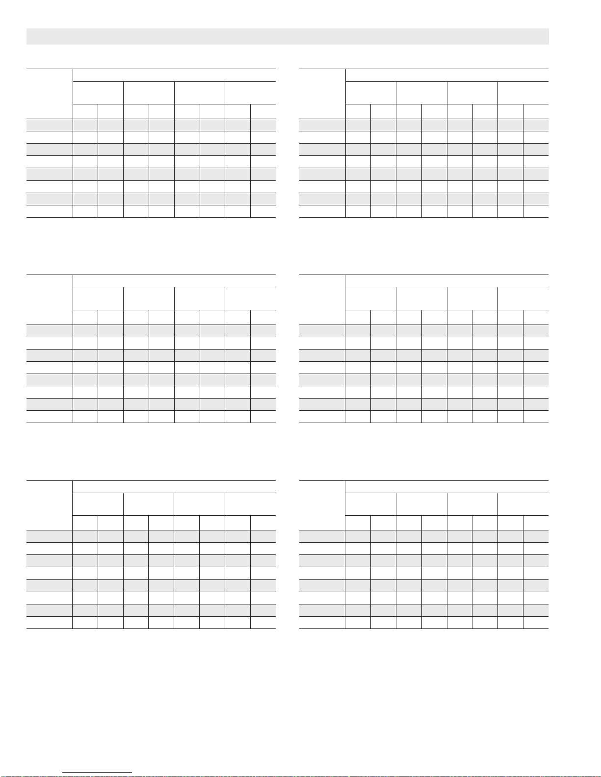
BLOWER DATA
ML180DF045P24A PERFORMANCE (Less Filter)
External
Static
Pressure
in. w.g.
0.10 1157 399 938 333 764 273 699 243
0.20 1120 381 924 322 745 264 677 237
0.30 1084 362 890 311 723 258 650 230
0.40 1027 349 864 298 695 250 633 224
0.50 975 334 814 283 674 238 605 215
0.60 902 322 764 268 623 225 564 203
0.70 831 305 682 248 549 208 477 186
0.80 713 280 576 228 470 192 401 171
ML180DF070P36A PERFORMANCE (Less Filter)
External
Static
Pressure
in. w.g.
0.10 1562 591 1386 539 1159 436 956 374
0.20 1506 553 1355 504 1149 418 953 361
0.30 1459 528 1314 473 1119 392 941 343
0.40 1390 500 1264 442 1082 374 915 323
0.50 1306 477 1200 415 1048 352 904 305
0.60 1213 441 1129 391 987 332 849 288
0.70 1140 417 1066 361 901 304 798 270
0.80 1038 395 975 342 836 283 717 244
Air Volume / Watts at Various Blower Speeds
High
cfm Watts cfm Watts cfm Watts cfm Watts
Air Volume / Watts at Various Blower Speeds
High
cfm Watts cfm Watts cfm Watts cfm Watts
Medium-
High
Medium-
High
Medium-
Low
Medium-
Low
Low
Low
ML180DF045P36A PERFORMANCE (Less Filter)
External
Static
Pressure
in. w.g.
0.10 1524 567 1385 528 1144 431 947 366
0.20 1465 542 1351 490 1129 407 943 354
0.30 1414 517 1293 463 1111 393 950 341
0.40 1343 489 1236 436 1083 371 945 329
0.50 1255 464 1190 409 1038 356 897 311
0.60 1205 443 1106 380 999 333 870 292
0.70 1140 421 1059 366 943 317 816 275
0.80 1031 388 962 335 870 297 739 252
ML180DF090P36B PERFORMANCE (Less Filter)
External
Static
Pressure
in. w.g.
0.10 1695 647 1431 546 1180 468 973 379
0.20 1641 611 1405 516 1162 443 967 368
0.30 1595 589 1384 492 1146 420 958 349
0.40 1525 548 1344 472 1136 399 954 337
0.50 1438 515 1271 432 1110 374 929 319
0.60 1370 489 1197 400 1057 352 886 299
0.70 1260 451 1119 374 983 328 823 273
0.80 1164 425 1020 344 900 300 743 249
Air Volume / Watts at Various Blower Speeds
High
cfm Watts cfm Watts cfm Watts cfm Watts
Air Volume / Watts at Various Blower Speeds
High
cfm Watts cfm Watts cfm Watts cfm Watts
Medium-
High
Medium-
High
Medium-
Low
Medium-
Low
Low
Low
ML180DF090P48B PERFORMANCE (Less Filter)
External
Static
Pressure
in. w.g.
0.10 1929 755 1794 668 1585 572 1332 489
0.20 1864 717 1745 623 1544 540 1321 463
0.30 1779 683 1676 588 1496 510 1296 440
0.40 1694 647 1600 558 1443 473 1265 417
0.50 1596 607 1502 511 1363 440 1212 393
0.60 1483 577 1413 485 1258 406 1148 370
0.70 1340 544 1273 449 1148 374 1042 339
0.80 1221 505 1138 416 1018 350 917 307
Air Volume / Watts at Various Blower Speeds
High
cfm Watts cfm Watts cfm Watts cfm Watts
Medium-
High
Medium-
Low
Low
ML180DF110P60C PERFORMANCE (Less Filter)
External
Static
Pressure
in. w.g.
0.10 2760 1401 2325 1045 1888 871 1531 686
0.20 2670 1362 2319 1003 1937 847 1565 679
0.30 2557 1292 2257 964 1945 832 1605 674
0.40 2536 1287 2220 949 1935 812 1622 661
0.50 2384 1230 2152 9 11 1918 782 1626 644
0.60 2273 1191 2063 884 1884 762 1617 630
0.70 2197 1151 2021 875 1822 737 1574 610
0.80 2115 1140 1950 854 1749 708 1517 579
Air Volume / Watts at Various Blower Speeds
High
cfm Watts cfm Watts cfm Watts cfm Watts
Medium-
High
Medium-
Low
Low
Page 4
Page 5
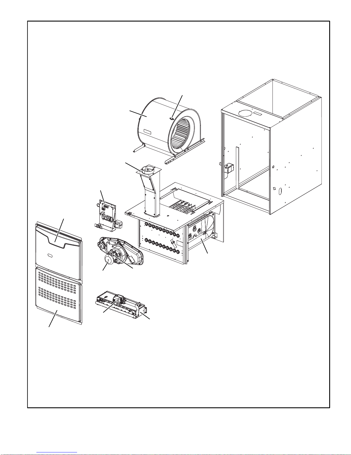
Blower Assembly
Flue Chase
Control Box
(includes integrated control,
interlock switch and transformer)
ML180DF PARTS ARRANGEMENT
Secondary Limit
Blower Access Panel
Heating Compartment
Access Panel
Primary Limit
(under combustion
air inducer)
Gas Valve
Heat Exchanger
Combustion
Air Inducer
Burner Box
(includes sensor, ignitor
and rollout switches)
FIGURE 1
Page 5
Page 6

I-UNIT COMPONENTS
ML180DF unit components are shown in figure 1.The gas
valve, combustion air inducer and burners can be ac
cessed by removing the heating compartment access pan
el. Electrical components are in the control box (figure 2)
found in the blower section.
CAUTION
Electrostatic discharge can affect elec
tronic components. Take precautions
to neutralize electrostatic charge by
touching your hand and tools to metal
prior to handling the control.
1. Control Transformer (T1)
A transformer located in the control box provides power to
the low voltage section of the unit. Transformers on all
models are rated 40VA with a 120V primary and a 24V sec
ondary.
2. Door Interlock Switch (S51)
A door interlock switch rated 14A at 125VAC is wired in se
ries with line voltage. When the blower door is removed the
unit will shut down.
CONTROL BOX ML180DF
Integrated Control
Door
Interlock
Switch
FIGURE 2
Transformer
3. Integrated Control (A92)
WARNING
Shock hazard.
Disconnect power before servicing. Control is not
field repairable. If control is inoperable, simply re
place entire control.
Can cause injury or death. Unsafe operation will re
sult if repair is attempted.
The hot surface ignition control system consisting of an in
tegrated control (figure 3 with control terminal designa
tions in tables 1 and 2), flame sensor and ignitor (figure 6).
The integrated control and ignitor work in combination to
ensure furnace ignition and ignitor durability. The inte
grated control, controls all major furnace operations. The
integrated control also features a RED LED for trouble
shooting and two accessory terminals rated at (1) one
amp. See table 3 for troubleshooting diagnostic codes.
The 120 volt ignitor is made from a high strength, silicon
nitride material that provides long life and trouble free
maintenance.
Electronic Ignition (Figure 4)
On a call for heat the integrated control monitors the com
bustion air inducer pressure switch. The control will not be
gin the heating cycle if the pressure switch is closed (bypassed). Once the pressure switch is determined to be
open, the combustion air inducer is energized. When the
differential in the pressure switch is great enough, the pres
sure switch closes and a 15-second pre-purge begins. If
the pressure switch is not proven within 2-1/2 minutes, the
integrated control goes into Watchguard-Pressure Switch
mode for a 5-minute re-set period.
After the 15-second pre-purge period, the ignitor warms up
for 20 seconds after which the gas valve opens for a 4-sec
ond trial for ignition. The ignitor remains energized for the
first 3 seconds of trial for ignition. If ignition is not proved
during the trial for ignition, the integrated control will try four
more times with an inter purge and warm-up time between
trials of 30 seconds. After a total of five trials for ignition (in
cluding the initial trial), the integrated control goes into
Watchguard-Flame Failure mode. After a 60-minute reset
period, the integrated control will begin the ignition se
quence again.
Page 6
Page 7
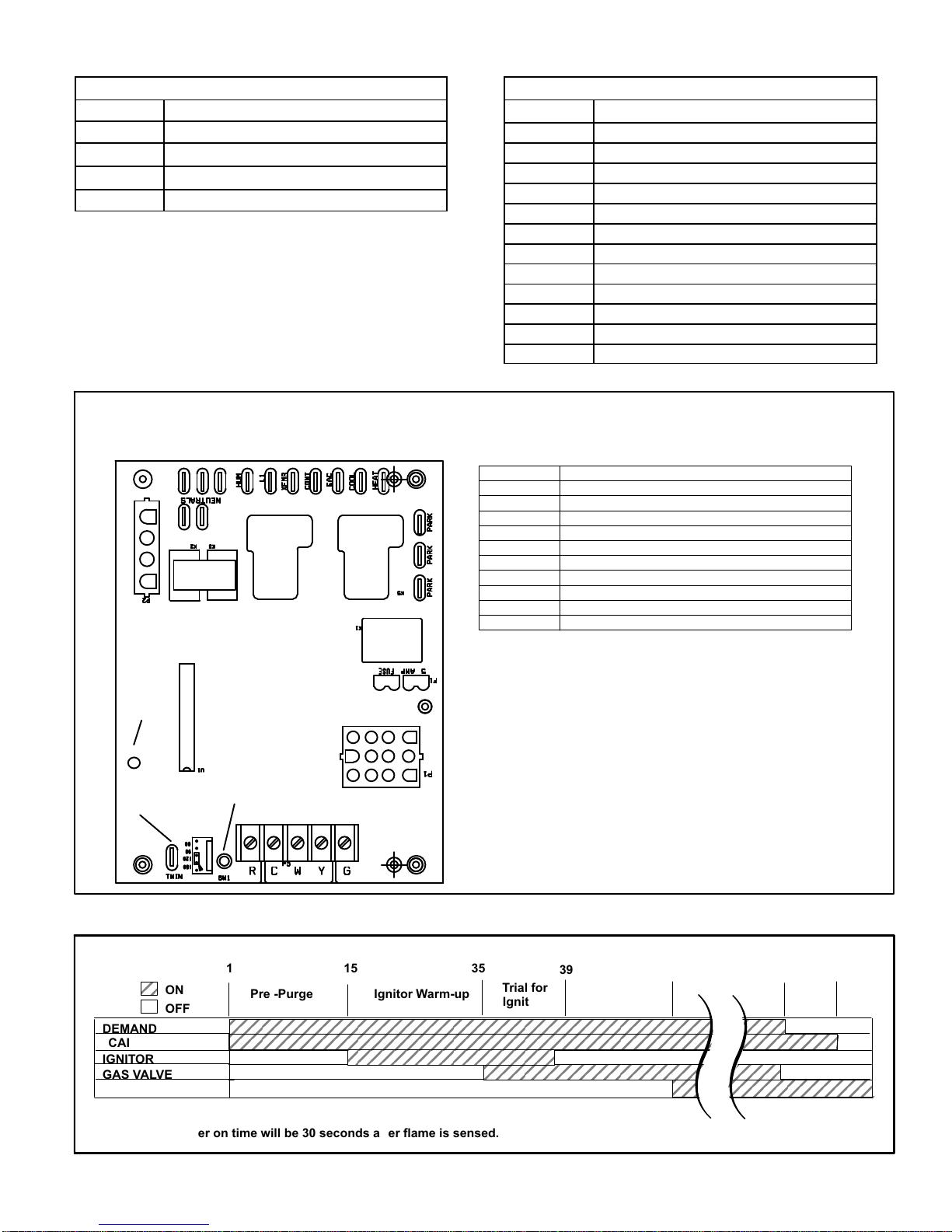
TABLE 1
4-Pin Terminal Designation
PIN # FUNCTION
1 Combustion Air Inducer Line
2
3
4
Ignitor Line
Combustion Air Inducer Neutral
Ignitor Neutral
12-Pin Terminal Designations
PIN # FUNCTION
1 High Limit Output
2 Sensor
3 24V Line
4 Not Used
5 Rollout Switch Out
6 24V Neutral
7 High Limit Input
8 Ground
9 Gas Valve Common
10 Pressure Switch In
11 Rollout Switch In
12 Gas Valve Out
INTEGRATED CONTROL
(Automatic Hot Surface Ignition System)
TERMINAL DESIGNATIONS
HUM
LINE
XFMR
EAC
COOL
HEAT
PARK
CONT
NEUTRALS
TWIN
Humidifier (120VAC)
Input (120VAC)
Transformer (120VAC)
Indoor Air Qality Accessory Air Cleaner (120VAC)
Blower - Cooling Speed (120VAC)
Blower - Heating Speed (120VAC)
Dead terminals to park alternate spd taps
Continuous blower
Neutral terminals (120VAC)
Twinning Terminal (24VAC)
TABLE 2
LED
TWIN
ON
OFF
DEMAND
CAI
IGNITOR
GAS VALVE
INDOOR BLOWER
*Blower on time will be 30 seconds after flame is sensed. Blower off time will depend on “OFF TIME” Setting.
PUSH BUTTON
1
Pre -Purge Ignitor Warm-up
15
FIGURE 3
ELECTRONIC IGNITION
35
Trial for
Ignition
39
Blower “On”*
Delay
5 SEC69
Post
Purge
FIGURE 4
Page 7
Page 8

TABLE 3
Note - This control is equipped with a push button switch for
diagnostic code recall. The control stores the last 5 fault
codes in non-volatile memory. The most recent fault code is
flashed first, the oldest fault code is flashed last. There is a
2 second pause between codes. When the push button
switch is pressed for less than 5 seconds, the control will
flash the stored fault codes when the switch is released.
The fault code history may be cleared by pressing the push
button switch for more than 5 seconds.
Integrated Control Diagnostic Codes
DIAGNOSTIC CODES
LED Status DESCRIPTION
LED Off
LED On Normal operation.
No power to control or control harware
fault detected.
Fan Time Control
Heating Fan On Time
The fan on time of 30 seconds is not adjustable.
Heating Fan Off Time
Fan off time (time that the blower operates after the heat
demand has been satisfied) can be adjusted by moving the
jumper to a different setting. The unit is shipped with a fac
tory fan off setting of 120 seconds. For customized comfort,
monitor the supply air temperature once the heat demand
is satisfied. Note the supply air temperature at the instant
the blower is de-energized.
Adjust the fan-off delay to achieve a supply air temperature
between 90° - 110° at the instant the blower is de-ener
gized. (Longer delay times allow for lower air temperature,
shorter delay times allow for higher air temperature). See
figure 5.
Cooling Fan On Time
The fan on time is 2 seconds and is not adjustable.
Cooling Fan Off Time
The control has a 60 second fan off delay after cooling de
mand has been met. This delay is factory set and not ad
justable.
1 Flash
2 Flashes
3 Flashes
4 Flashes Primary limit switch open.
5 Flashes Rollout switch open.
6 Flashes Pressure switch cycle lockout.
7 Flashes Lockout, burners fail to light.
8 Flashes
Flame present with gas vavle
de-energized.
Pressure switch closed with combustion
air inducer de-energized.
Pressure switch open with combus
tion air inducer energized.
Lockout, buners lost flame too many
times.
9 Flashes Line voltage polarity incorrect.
HEAT FAN‐OFF TIME IN SECONDS
NO JUMPER
To adjust fan-off timing, reposition jumper across pins to
60 Second
off Time
60
90
120
180
achieve desired setting.
90 Second
off Time
60
90
120
180
120 Second
off Time
60
90
120
180
FIGURE 5
180 Second
off Time
60
90
120
180
Page 8
Page 9
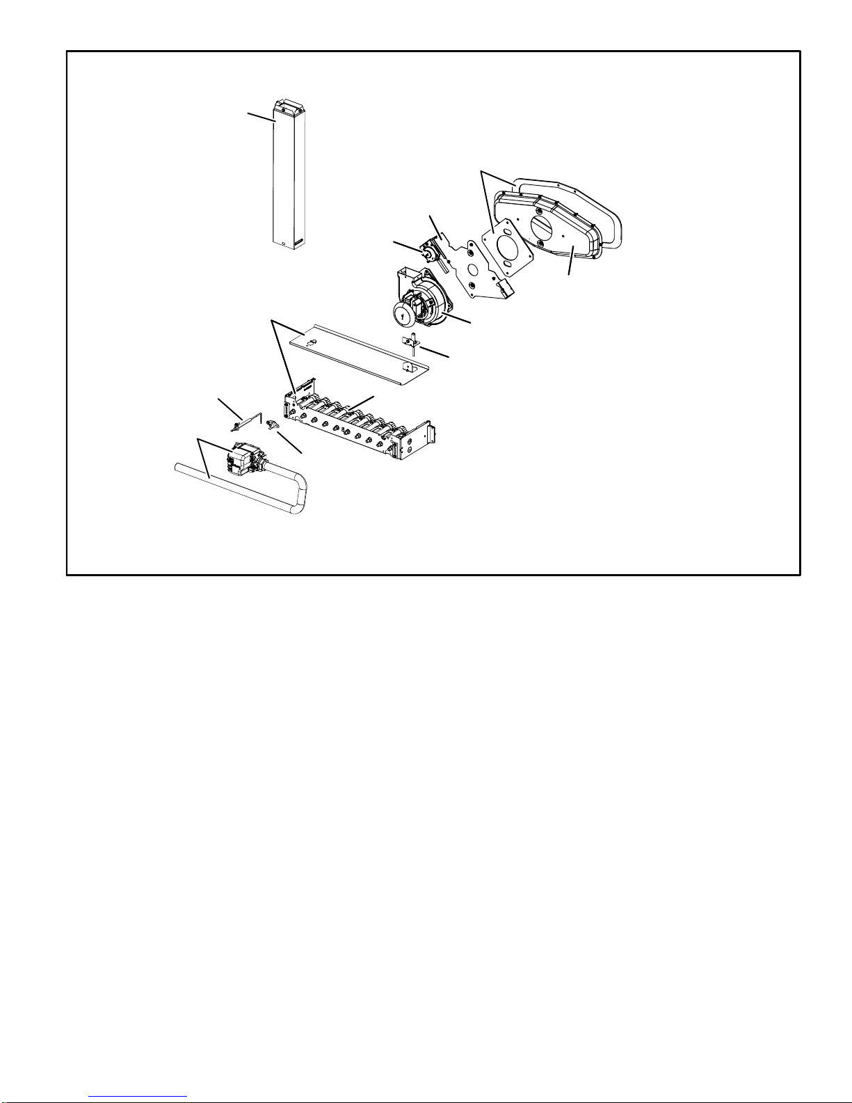
Internal flue pipe
Burner box
assembly
ML180DF HEATING COMPONENTS
Gasket
Orifice plate
Pressure switch
Collector box
Combustion air inducer
Ignitor
Rollout
switch
Burners
Manifold and
Gas valve
Sensor
FIGURE 6
4. Flame Rollout Switch (Figure 6)
Flame rollout switch (S47) is a high temperature limit. The
limit is a N.C. SPST manual‐reset limit connected in series
with the integrated control A92. When S47 senses rollout,
the integrated control immediately stops ignition and
closes the gas valve. If unit is running and flame rollout is
detected, the gas valve will close and integrated control will
be disabled. Rollout can be caused by a blocked heat ex
changer, blocked flue or lack of combustion air. The switch
has a factory setpoint of 210°F and cannot be adjusted. To
manually reset a tripped switch, push the reset button located
on the control.
5. Primary Limit Control
The primary limit on ML180DF units is located in the heating
vestibule panel under the combustion air inducer. When ex
cess heat is sensed in the heat exchanger, the limit will open. If
the limit is open, the integrated control energizes the supply air
blower and closes the gas valve. The limit automatically resets
when unit temperature returns to normal. The switch must re
set within three minutes or the control will go into Watchguard
for one hour. The switch is factory set and cannot be ad
justed. The switch may have a different setpoint for each unit
model number. If limit switch must be replaced, refer to Len
nox ProductZone repair parts list on Lennox DaveNet®.
6. Flame Sensor (Figure 6)
A flame sensor is located on the left side of the burner sup
port. The sensor is mounted on the flame rollout plate and
the tip protrudes into the flame envelope of the left-most
burner. The sensor can be removed for service (clean us
ing steel wool) without removing any part of the burners.
During operation, flame is sensed by current passed
through the flame and sensing electrode. The integrated
control allows the gas valve to remain open as long as
flame signal is sensed.
A microamp DC meter is needed to check the flame signal
on the integrated control.
Flame (microamp) signal is an electrical current which passes
from the integrated control to the sensor during unit operation.
Current passes from the sensor through the flame to ground to
complete a safety circuit.
Page 9
Page 10

To Measure Flame Signal - Integrated Control:
Use a digital readout meter capable of reading DC micro
amps. See figure 7 and table 4 for flame signal check.
1 - Set the meter to the DC amps scale.
2 - Turn off supply voltage to control.
3 - Remove sensor wire from integrated control.
4 - Connect (-) lead to flame sensor wire.
5 - Connect (+) lead to Terminal FS on integrated control.
Measuring Flame Signal
(upflow furnace shown)
6 - Turn supply voltage on and close thermostat contacts to
cycle system.
7 - When main burners are in operation for two minutes, take
reading.
TABLE 4
Flame Signal in Microamps
Normal Low Drop Out
1.5
0.5 - 1.4
0.4
Flame
Sensor
Flame Sensor
Wire
Integrated
Control
(+)
Flame Sensor
Terminal
(+) To Control
Sensor
Terminal
Remove Sensor Wire from
Integrated Control and
Connect Alligator Clip (−)
to Flame Sensor Lead
DIGITAL METER
Set dial to measure dc microamps
Red Collar
Indicates
Positive Lead
(+)
(-) To
flame
sensor
Remove Sensor Wire from
Integrated Control and
Connect Alligator Clip (+)
to Terminal on Control
FIGURE 7
Page 10
Page 11

7. Ignitor (Figure 6)
The nitride ignitor used on ML180DF units is made from a
proprietary ceramic material. To check ignitor, measure its
resistance and voltage. A value of 39 to 70 ohms indicates
a good ignitor. Voltage to the ignitor should be 120VAC.
See figure 8 for resistance, and voltage check.
NOTE - The ML180DF furnace contains electronic
components that are polarity sensitive. Make sure that
the furnace is wired correctly and is properly grounded.
Check ignitor circuit for correct resistance.
Test 1
Remove 4-pin plug from control.
Check ohms reading across terminals 2 and 4.
If value is correct (39 to 70 ohms), this is the only test
needed.If the reading on the meter is not correct,
(0 or infinity) then a second test is needed.
Test 2
Check ignitor for correct resistance.
Seperate the 2-pin jack-plug near the manifold and check
resistance of ignitor at the plug. Reading should be
between 39 and 70 ohms. If the reading is correct, then
the problem is with the wiring between the jack-plug and
the control. If reading is not correct, the issue is the ignitor.
Test 2
Test 1
Integrated Control Board
Detail
Insert meter probes into terminals 2 and 4 (use small
Check ignitor for correct voltage
diameter probes in order not to damage plug).
Check voltage during 20 second ignitor warm up period.
Voltage should read 120 volts +
these values, check for correct supply voltage to furnace.
Test 3
10%. If voltage reads below
Integrated Control Board
Detail
Test 3
Integrated Control Board
Detail
FIGURE 8
Page 11
Page 12

8. Gas Valve (Figure 6)
The ML180DF uses internally redundant gas valve to as
sure safety shut-off. If the gas valve must be replaced, the
same type valve must be used.
24VAC terminals and valve switch are located on the valve. All
terminals on the gas valve are connected to wires from the in
tegrated control. 24V applied to the terminals energizes the
valve.
Inlet and outlet pressure taps are located on the valve. A regu
lator adjustment screw is located on the valve.
LPG changeover kits are available from Lennox. Kits include
burner orifices and a gas valve regulator spring.
9. Combustion Air Inducer (B6)
All ML180DF units use a combustion air inducer to move air
through the burners and heat exchanger during heating op
eration. The blower uses a 120VAC motor. The motor oper
ates during all heating operation and is controlled by inte
grated control A92. The inducer also operates for 15 sec
onds before burner ignition (pre‐purge) and for 5 seconds
after the gas valve closes (post‐purge).
A pressure switch mounted on the combustion air inducer ori
fice plate is used to prove inducer operation. The combustion
air inducer orifice will be different for each model. See table 5
for orifice sizes. The switch monitors air pressure in the induc
er housing. During normal operation, the pressure in the
housing is negative. If pressure becomes less negative (sig
nifying any obstruction in the flue) the pressure switch opens.
When the proving switch opens, the integrated control (A92)
immediately de-energizes the gas valve to prevent burner
operation.
TABLE 5
ML180DF Unit
C.A.I. Orifice Size
045P24A 1.094
045P36A 1.063
070(X)P36A 1.344
090P36B 1.531
090(X)P48B 1.531
110(X)P60C 1.718
10. Combustion Air Inducer
Pressure Switch (S18)
ML180DF series units are equipped with a combustion air
pressure switch located on the combustion air inducer ori
fice bracket. The switch is connected to the combustion air
inducer housing by means of a flexible silicone hose. It mon
itors negative air pressure in the combustion air inducer
housing.
The switch is a SPST Normally open proving switch electri
cally connected to the furnace control. The purpose of the
switch is to prevent burner operation if the combustion air in
ducer is not operating or if the flue becomes obstructed.
On start‐up, the switch senses that the combustion air in
ducer is operating. It closes a circuit to the integrated con
trol when pressure inside the combustion air inducer de
creases to a certain set point. Set points vary depending on
unit size. See table 6. The pressure sensed by the switch is
negative relative to atmospheric pressure. If the flue be
comes obstructed during operation, the switch senses a
loss of negative pressure (pressure becomes more equal
with atmospheric pressure) and opens the circuit to the in
tegrated control and gas valve. A bleed port on the switch
allows relatively dry air in the vestibule to purge switch tub
ing, to prevent condensate build up.
TABLE 6
ML180DF Set Point inches w.c.
045P24A 0.60
045P36A 0.60
070(X)P36A 0.65
090P36B 0.60
090(X)P48B 0.60
110(X)P60C 0.65
110P60C 0.69
The switch is factory set and is not field adjustable. It is a
safety shut‐down control in the furnace and must not be bypassed for any reason. If switch is closed or by-passed, the
integrated control will not initiate ignition at start up.
Troubleshooting
See figure 9 for measuring operating pressure and check
ing resistance in the pressure switch.
Page 12
Page 13

MULTI−METER
SET TO MEASURE OHMS
Pressure Switch
FIGURE 9
Remove tubing from CAI and
insert “Tee” and additional tubing.
To
Field Provided
Tubing To CAI Port
High
or
Low
11. Blower Motors and Capacitors
All ML180DF units use direct drive blower motors. All motors
are 120V permanent split capacitor motors to ensure maxi
mum efficiency. See Specifications section at the front of this
manual for motor specifications. Ratings for capacitors will
be on motor nameplate.
12. Secondary Limit Control
The secondary limit is located in the blower compartment on
the back side of the blower housing. See figure 10. When ex
cess heat is sensed in the blower compartment, the limit will
open. If the limit is open, the furnace control energizes the sup
ply air blower and closes the gas valve. The limit automatically
resets when unit temperature returns to normal. The secon
dary limit cannot be adjusted.
Supply Air Blower
To Remove Blower From Unit:
1. Disconnect Power, 2. Remove internal flue pipe and chase
3. Remove Control Box 4. Remove Bolts. 5. Unplug Motor
Wires From Control Board. Then Slide Out Front of Unit.
FIGURE 10
Page 13
Page 14

II- PLACEMENT AND INSTALLATION
Make sure unit is installed in accordance with installation
instructions and applicable codes.
III- START‐UP
A- Heating Start‐Up
WARNING
Shock and burn hazard.
ML180DF units are equipped with a hot surface igni
tion system. Do not attempt to light manually.
Gas Valve Operation
MANIFOLD
PRESSURE
ADJUSTMENT
SCREW
INLET
PRESSURE
PORT
1 - STOP! Read the safety information at the beginning of
this section.
2 - Set the thermostat to the lowest setting.
3 - Turn off all electrical power to the unit.
4 - This furnace is equipped with an ignition device which
automatically lights the burners. Do not try to light the
burners by hand.
5 - Remove the heating compartment access panel.
6 - Move gas valve switch to OFF position. Do not
force. See figure 11.
7 - Wait five minutes to clear out any gas. If you then smell
gas, STOP! Immediately call your gas supplier from a
neighbor's phone. Follow the gas supplier's instruc
tions. If you do not smell gas go to next step.
8 - Move gas valve switch to ON position. Do not force.
See figure 11.
9 - Replace the heating compartment access panel.
10- Turn on all electrical power to to the unit.
11- Set the thermostat to desired setting.
NOTE - When unit is initially started, steps 1 through 11
may need to be repeated to purge air from gas line.
12- If the appliance will not operate, follow the instructions
“Turning Off Gas to Unit” and call the gas supplier.
Turning Off Gas to Unit
1 - Set the thermostat to the lowest setting.
GAS VALVE SHOWN IN ON POSITION
FIGURE 11
MANIFOLD
PRESSURE
OUTLET
PORT
2 - Turn off all electrical power to the unit if service is to be
performed.
3 - Remove the heating compartment access panel.
4 - Move gas valve switch to OFF position. Do not
force. See figure 11.
5 - Replace the heating compartment access panel.
B- Safety or Emergency Shutdown
Disconnect main power to unit. Close manual and main gas
valves.
C- Extended Period Shutdown
Turn off thermostat or set to “UNOCCUPIED” mode. Close
all gas valves (both internal and external to unit) to guaran
tee no gas leaks into combustion chamber. Turn off power
to unit. All access panels and covers must be in place and
secured.
IV-HEATING SYSTEM SERVICE CHECKS
A- C.S.A. Certification
All units are C.S.A. design certified without modifications.
Refer to the ML180DF Installation Instruction.
B- Gas Piping
Gas supply piping should not allow more than 0.5”W.C. drop
in pressure between gas meter and unit. Supply gas pipe
must not be smaller than unit gas connection.
Compounds used on gas piping threaded joints should be
resistant to action of liquefied petroleum gases.
C- Testing Gas Piping
CAUTION
If a flexible gas connector is required or allowed by
the authority that has jurisdiction, black iron pipe
shall be installed at the gas valve and extend outside
the furnace cabinet.
IMPORTANT
In case emergency shutdown is required, turn off
the main shut‐off valve and disconnect the main
power to unit. These controls should be properly
labeled by the installer.
WARNING
Do not exceed 600 in-lbs (50 ft-lbs) torque when at
taching the gas piping to the gas valve.
When pressure testing gas lines, the gas valve must be dis
connected and isolated. Gas valves can be damaged if
subjected to more than 0.5 psig (14” W.C.). See figure 12. If
the pressure is equal to or greater than 0.5 psig (14”W.C.),
close the manual shut-off valve before pressure testing to
isolate furnace from gas supply.
Page 14
Page 15

GAS PIPING TEST PROCEDURE
MANUAL MAIN SHUT-OFF VALVE
WILL NOT HOLD TEST PRESSURE
IN EXCESS OF 0.5 PSIG (14”W.C.)
CAP
GAS VALVE
FIELD PROVIDED
LINE PRESSURE TAP
FIGURE 12
When checking piping connections for gas leaks, use pre
ferred means. Kitchen detergents can cause harmful corro
sion on various metals used in gas piping. Use of a specialty
Gas Leak Detector is strongly recommended. It is available
through Lennox under part number 31B2001. See Corp.
8411-L10, for further details.
Do not use matches, candles, flame or any other source of
ignition to check for gas leaks.
D- Gas Pressure Adjustment
Gas Flow (Approximate)
TABLE 7
GAS METER CLOCKING CHART
Seconds for One Revolution
ML180DF
Unit
Natural LP
1 cu ft
Dial
2 cu ft
Dial
1 cu ft
Dial
2 cu ft
DIAL
-045 80 160 200 400
-070 55 110 136 272
-090 41 82 102 204
-110 33 66 82 164
-135 27 54 68 136
Natural-1000 btu/cu ft LP-2500 btu/cu ft
Furnace should operate at least 5 minutes before check
ing gas flow. Determine time in seconds for two revolu
tions of gas through the meter. (Two revolutions assures a
more accurate time.) Divide by two and compare to time
in table 7. If manifold pressure matches table 9 and rate is
incorrect, check gas orifices for proper size and restric
tion. Remove temporary gas meter if installed.
NOTE - To obtain accurate reading, shut off all other gas
appliances connected to meter.
E- Supply and Manifold Pressure
Supply Pressure Measurement
1 - Remove the threaded plug from the inlet side of the
gas valve and install a field-provided barbed fitting.
Connect to a test gauge to measure supply pressure.
2 - Start unit and allow 5 minutes for unit to reach steady
state.
3 - After allowing unit to stabilize for 5 minutes, record
supply pressure and compare to value given in table 9.
Manifold Pressure Measurement
1 - Remove the threaded plug from the outlet side of the
gas valve and install a field-provided barbed fitting.
Connect to a test gauge to measure manifold pres
sure.
2 - Start unit and allow 5 minutes for unit to reach steady
state.
3 - While waiting for the unit to stabilize, observe the
flame. Flame should be stable and should not lift from
burner. Natural gas should burn blue.
4 - After allowing unit to stabilize for 5 minutes, record
manifold pressure and compare to value given in table
9.
NOTE - Shut unit off and remove manometer as soon as an
accurate reading has been obtained. Take care to remove
barbed fitting and replace threaded plug.
F- Proper Combustion
Furnace should operate a minimum 15 minutes with cor
rect manifold pressure and gas flow rate before checking
combustion. Take combustion sample beyond the flue out
let and compare to the tables below. The maximum carbon
monoxide reading should not exceed 50 ppm.
TABLE 8
ML180DF Unit
CO2%
Nat
For
CO2%
L.P.
For
-045
-070
-090
6.0 - 7.5 6.9 - 8.5
-110
G- High Altitude
The manifold pressure may require adjustment and com
bustion air pressure switch may need replacing to ensure
proper combustion at higher altitudes. Refer to table 9 for
manifold pressure and table 10 for pressure switch change
and gas conversion kits.
IMPORTANT
For safety, shut unit off and remove manometer as
soon as an accurate reading has been obtained.
Take care to replace pressure tap plug.
Page 15
Page 16

TABLE 9
Manifold Pressure Settings at all Altitudes
Model
Input Size
045
070
090
110
Model
Input Size
045
070 80W52
090 No Change
090(X)
110
High Altitude Pressure Switch Kit
0-4500 ft 4501-7500 ft 7501 - 10,000 ft 7501 - 10,000 ft 0 - 7500 ft 7501 - 10,000 ft 0 - 7500 ft
No Change
LP/propane 10.0 10.0 10.0 11.0 13.0
LP/propane 10.0 10.0 10.0 11.0 13.0
LP/propane 10.0 10.0 10.0 11.0 13.0
LP/propane 10.0 10.0 10.0 11.0 13.0
No Change
Supply Pressure
Gas 0-4500 ft 4501-7500 ft 7501 - 10,000 ft
Nat 3.5 3.5 3.5 4.5 13.0
Nat 3.5 3.3 3.5 4.5 13.0
Nat 3.5 3.3 3.5 4.5 13.0
Nat 3.5 3.3 3.5 4.5 13.0
in.wg.
Min Max
TABLE 10
Pressure Switch and Gas Conversion Kits at all Altitudes
80W52
High Altitude
Natural Gas Burner
Orifice Kit
80W51 73W37 70W89 76W15 73W81
Natural Gas to LP/Propane
Gas Change Over Kit
LP/Propane to
Natural Gas
Change Over Kit
NOTE - A natural to L.P. propane gas changeover kit is necessary to convert this unit. Refer to the changeover kit installation instruction for the conversion
procedure.
Page 16
Page 17

H- Proper Ground and Voltage
A poorly grounded furnace can contribute to premature ig
nitor failure. Use the following procedure to check for
ground and voltage to the integrated control.
1 - Measure the AC voltage between Line Neutral (spade
terminals) and “C” terminal (low voltage terminal
block) on the integrated control. See figure 13. A wide
variation in the voltage between Line Neutral and “C”
as a function of load indicates a poor or partial ground.
Compare the readings to the table below. If the read
ings exceed the maximum shown in table 1, make re
pairs before operating the furnace.
2 - In addition, measure the AC voltage from Line Hot to
Line Neutral (spade terminals) on the integrated con
trol. See figure 14. This voltage should be in the range
of 97 to 132 Vac
TABLE 11
Furnace Status
Power On Furnace Idle 0.3 2
CAI / Ignitor Energized 0.75 5
Indoor Blower Energized Less than 2 10
Measurement VAC
Expected Maximum
CHECK VOLTAGE BETWEEN LINE NEUTRAL
AND LOW VOLTAGE “C” TERMINAL
CHECK VOLTAGE BETWEEN LINE HOT
AND LINE NEUTRAL
FIGURE 13
FIGURE 14
Page 17
Page 18

V-TYPICAL OPERATING CHARACTERISTICS
A-Blower Operation and Adjustment
NOTE- The following is a generalized procedure and
does not apply to all thermostat controls.
1 - Blower operation is dependent on thermostat control
system.
2 - Generally, blower operation is set at thermostat sub
base fan switch. With fan switch in ON position, blower
operates continuously. With fan switch in AUTO position,
blower cycles with demand or runs continuously while
heating or cooling circuit cycles.
3 - Depending on the type of indoor thermostat, blower
and entire unit will be off when the system switch is in
OFF position.
B-Temperature Rise (Figure 15)
Temperature rise for ML180DF units depends on unit input,
blower speed, blower horsepower and static pressure as
marked on the unit rating plate. The blower speed must be
set for unit operation within the range of “TEMP. RISE °F”
listed on the unit rating plate.
C-External Static Pressure
1 - Tap locations shown in figure 16 .
2 - Punch a 1/4” diameter hole in supply and return air ple
nums. Insert manometer hose flush with inside edge of
hole or insulation. Seal around the hose with perma
gum. Connect the zero end of the manometer to the
discharge (supply) side of the system. On ducted sys
tems, connect the other end of manometer to the return
duct as above.
3 - With only the blower motor running and the evaporator
coil dry, observe the manometer reading. Adjust blow
er motor speed to deliver the air desired according to
the job requirements. For heating speed external static
pressure drop must not be more than 0.5” W.C. For
cooling speed external static pressure drop must not
be more than 0.8” W.C.
4 - Seal the hole when the check is complete.
EXTERNAL STATIC PRESSURE
Supply Duct Static
Return Duct Static +
Total Duct Static =
(dry coil)
Upflow Furnace Shown
TEMPERATURE RISE
Supply Duct Temperature _____
Return Duct Temperature - ____
Temperature Rise = _________
Upflow Furnace Shown
Supply Air
Return Air
FIGURE 15
Supply Air
High
Low
or
+
Return Air
-
FIGURE 16
D-Blower Speed Taps
Blower speed tap changes are made on the integrated con
trol. See figure 3. The heating tap is connected to the
“HEAT” terminal and the cooling tap is connected to the
“COOL” terminal. The continuous blower tap is connected
to the “CONT” terminal. Unused taps must be secured on
dummy terminals labeled ”PARK. To change out existing
speed tap, turn off power and switch out speed tap with tap
connected to “PARK”. See blower speed tap table on unit
diagram for motor tap colors for each speed.
Page 18
Page 19

VI-MAINTENANCE
A-Preliminary and Seasonal Checks
1 - Inspect electrical wiring, both field and factory installed
for loose connections. Tighten as required.
2 - Check voltage at disconnect switch. Voltage must be
within range listed on the nameplate. If not, consult the
power company and have voltage condition corrected
before starting unit.
At the beginning of each heating season, the system
should be checked as follows:
B-Filters
Filters should be inspected monthly. Clean or replace the
filters when necessary to ensure that the furnace operates
properly. Replacement filters must be rated for high veloc
ity airflow. See table 12.
IMPORTANT
If a highefficiency filter is being installed as part of
this system to ensure better indoor air quality, the fil
ter must be properly sized. Highefficiency filters
have a higher static pressure drop than standardef
ficiency glass/foam filters. If the pressure drop is too
great, system capacity and performance may be re
duced. The pressure drop may also cause the limit to
trip more frequently during the winter and the indoor
coil to freeze in the summer, resulting in an increase
in the number of service calls.
Before using any filter with this system, check the
specifications provided by the filter manufacturer
against the data given in the appropriate Lennox
Product Specifications bulletin. Additional informa
tion is provided in Service and Application Note
ACC002 (August 2000).
TABLE 12
Cabinet Width Return Air Filter Size (inches)
A (14-1/2”) 14 x 25 x 1 (1)
B (17-1/2”) 16 x 25 x 1 (1)
C (21”) 20 x 25 x 1 (1)
Cleaning the Heat Exchanger and Burners
NOTE - Use papers or protective covering in front of the fur
nace during cleaning.
1 - Turn off both electrical and gas power supplies to fur
nace.
2 - Remove flue pipe, top cap, flue chase and internal flue
pipe assembly from the unit.
3 - Label the wires from gas valve, rollout switches, prima
ry limit switch and make-up box then disconnect them.
4 - Remove the screws that secure the combustion air in
ducer/pressure switch assembly to the collector box.
Carefully remove the combustion air inducer to avoid
damaging blower gasket. If gasket is damaged, it must
be replaced to prevent leakage.
5 - Remove the collector box located behind the combus
tion air inducer. Be careful with the collector box gas
ket. If the gasket is damaged, it must be replaced to
prevent leakage.
6 - Disconnect gas supply piping. Remove the four screws
securing the burner manifold assembly to the vestibule
panel and remove the assembly from the unit.
7 - NOX units only - Remove screw securing NOX insert.
Remove NOX insert.
8 - Remove screws from both sides, top and bottom of
vestibule panel.
9 - Remove heat exchanger. It may be necessary to
spread cabinet side to allow more room. If so, remove
five screws from the left side or right side of cabinet.
See figure 18.
10- Back wash using steam. Begin from the burner opening
on each clam. Steam must not exceed 275°F.
11- To clean burners, run a vacuum cleaner with a soft brush
attachment over the face of burners. Visually inspect in
side the burners and crossovers for any blockage
caused by foreign matter. Remove any blockage. Figure
17 shows burner detail.
12- To clean the combustion air inducer visually inspect and
using a wire brush clean where necessary. Use com
pressed air to clean off debris and any rust.
13- Reinstall heat exchanger in vestibule. (Replace the
five screws in the cabinet from step 10 if removed).
14- NOX units only - replace NOX inserst.
15- Reinstall collector box, combustion air assembly, inter
nal flue pipe and flue chase. Seal with high tempera
ture RTV. Reinstall all screws to the collector box and
combustion air inducer. Failure to replace all screws
may cause leaks. Inspect gaskets for any damage and
replace if necessary.
Page 19
Page 20

Gasket
ML180DF BURNER, COMBUSTION AIR INDUCER ASSEMBLY &
HEAT EXCHANGER REMOVAL
Internal flue pipe
Gasket
Combustion air inducer
Ignitor
Manifold and
Gas valve
Glue chase
Burner box
assembly
Sensor
Pressure switch
Burners
Rollout
switch
Orifice plate
FIGURE 17
16- Reinstall burner box, manifold assembly and burner box
cover.
17- Reconnect all wires.
Collector box
Heat exchanger
Nox insert
(if applicable)
Retention rings
Cross over
Remove five screws if necessary
(either side of cabinet)
18- Reconnect top cap and vent pipe to combustion air in
ducer outlet.
19- Reconnect gas supply piping.
20- Turn on power and gas supply to unit.
21- Set thermostat and check for proper operation.
22- Check all piping connections, factory and field, for gas
leaks. Use a leak detecting solution or other preferred
means.
CAUTION
Some soaps used for leak detection are corrosive to
certain metals. Carefully rinse piping thoroughly af
ter leak test has been completed. Do not use
matches, candles, flame or other sources of ignition
to check for gas leaks.
23- If a leak is detected, shut gas and electricity off and
repair leak.
24- Repeat steps 22 and 23 until no leaks are detected.
25- Replace access panel.
4
3
5
2
1
FIGURE 18
Page 20
Page 21

C-Supply Air Blower
1 - Check and clean blower wheel.
2 - Motors used on the Lennox ML180DF series units
are permanently lubricated and need no further lu
brication.
D-Flue and Chimney
Flue must conform to local codes. In the absence of local
codes, flue must meet the National Fuel Gas Code
ANSI-Z223.1 venting requirements. Flue pipe deteriorates
from the inside out and must be disconnected in order to
check thoroughly. Check flue pipe, chimney and all con
nections for tightness and to make sure there is no block
age or leaks.
E-Electrical
1 - Check all wiring for loose connections.
2 - Check for the correct voltage at the furnace (furnace
operating). Correct voltage is 120VAC +
10%
3 - Check amp-draw using a true RMS meter on the blow
er motor with blower access panel in place. See figure
19.
Furnace Nameplate__________Actual__________
Check Motor AMP Draw
(upflow furnace shown)
OFF
P
−
EX
MR
W
3
2
1
kWh
kVAr
COMMV3V1
V2
True RMS Meter
FIGURE 19
Page 21
Page 22

VII- WIRING AND SEQUENCE OF OPERATION
ML180DF Schematic Wiring Diagram and Sequence of Operation
3
10
1
4
5
5
1
1 - Line voltage is applied to L1 and N. the T1 low voltage transformer is energized, and line voltage is applied to B3 indoor blower.
2 - S47 rollout switch must be closed in order for 24V from transformer to be output on integrated control ”R” to power thermostat.
3 - When there is a call for heat, W1 of the thermostat energizes W of the furnace control with 24VAC.
4 - A92 integrated control runs a self-check. S10 primary limit and S21 secondary limit contacts are found to be closed. Call for heat can continue.
5 - A92 integrated control energizes B6 combustion air inducer. S18 combustion air pressure switch closes . Once S18 closes, a 15-second
pre-purge follows.
6 - A92 integrated control energizes R33 ignitor. A 20-second warm-up period begins.
7 - GV1 gas valve opens for a 4-second trial for ignition
8 - Flame is sensed, gas valve remains open for the heat call.
9 - After 30-second delay (from flame sensed), A92 integrated control applies 24VAC to Heat speed of B3 indoor blower.
10 - When heat demand is satisfied, W1 of the indoor thermostat de-energizes W of A92ignition control which de-energizes GV1 gas valve.
B6 combustion air inducer continues a 5-second post-purge period, and B3 indoor blower completes a selected OFF time delay.
6
8
9
2
7
Page 22
Page 23

Troubleshooting: Heating Sequence of Operation
HEATING SEQUENCE OF OPERATION
NORMAL HEATING MODE
POWER ON
CONTROL SELF-CHECK OKAY?
YES
IS POLARITY CORRECT?
YES
IS THERE A PROPER GROUND?
YES
IS VOLTAGE
ABOVE 90 VOLTS?
YES
ROLLOUT SWITCH CLOSED?
YES
NO
NO
NO
ABNORMAL HEATING MODE
GAS VALVE OFF. COMBUSTION AIR INDUCER OFF.
NO
NO
CONTROL WILL NOT RESPOND TO CALL FOR HEAT
IGNITOR WILL GLOW DIMLY BUT WILL NOT LIGHT
GAS VALVE OFF. COMBUSTION AIR INDUCER ON.
SEQUENCE HOLDS UNTIL ROLLOUT SWITCH CLOSES
AND POWER IS RESET OR T'STAT IS INTERRUPTED
INDOOR BLOWER DELAY OFF.
LED: OFF
POLARITY REVERSED.
LED: 9 FLASHES
IMPROPER GROUND.
LED: OFF
UNTIL PROPER GROUND.
LED: ON STEADY
INDOOR BLOWER ON.
LED: 5 FLASHES
FOR MINIMUM OF 1 SECOND.
NO
BURNER OFF?
(Contiuous Flame Check)
YES
NORMAL OPERATION:
LED: STEADY ON
YES
THERMOSTAT CALLS FOR HEAT:
LED: STEADY ON
YES
PRIMARY AND SECONDARY LIMIT SWITCH.
CLOSED?
YES
IS COMBUSTION AIR
PRESSURE SWITCH OPEN?
YES
IS COMBUSTION AIR INDUCER
ENERGIZED?
YES
HAS COMBUSTION AIR PRESSURE
SWITCH CLOSED IN 2.5 MINUTES?
YES
CONTINUED NEXT PAGE
NO
NO
GAS VALVE OFF. COMBUSTION AIR INDUCER ON.
INDOOR BLOWER ON HEATING SPEED.
COMBUSTION AIR INDUCER OFF.
NO
NO
PRESSURE SWITCH IS IN WATCHGUARD MODE.
GAS VALVE OFF. COMBUSTION AIR INDUCER OFF.
INDOOR BLOWER OFF WITH DELAY.
IS 5‐MINUTE RESET PERIOD COMPLETE?
LED: 1 FLASH
INDOOR BLOWER ON
LED: 4 FLASHES
GAS VALVE OFF.
COMBUSTION AIR INDUCER OFF.
INDOOR BLOWER OFF WITH DELAY.
LED: 2 FLASHES
(Sequence holds until pressure switch
opens or thermostat resets control.)
LED: 3 FLASHES
YES
Page 23
Page 24

Troubleshooting: Heating Sequence of Operation (Continued)
HEATING SEQUENCE CONTINUED
NORMAL HEATING MODE ABNORMAL HEATING MODE
15‐SECOND COMBUSTION AIR INDUCER PREPURGE
INITIATED BY CLOSED PRESSURE SWITCH.
YES
IGNITOR WARM‐UP -- 20 SECONDS.
YES
4‐SECOND TRIAL FOR IGNITION.
GAS VALVE OPENS.
YES
FLAME STABILIZATION PERIOD.
4 SECONDS
FLAME RECTIFICATION CURRENT
CHECK. CAN FLAME BE PROVEN WITHIN
4 SECONDS AFTER GAS VALVE OPENS?
YES
FLAME PRESENT?
NO
IS VOLTAGE ABOVE 90 VOLTS?
YES
GAS VALVE OFF. COMBUSTION AIR INDUCER ON.
NO
HAS CONTROL FAILED TO SENSE FLAME FOR
FIVE CONSECUTIVE TRIES DURING A SINGLE
WATCHGUARD MODE. GAS VALVE OFF.
LED: 7 FLASHES WATCHGUARD FAILURE CODE.
IS 60‐MINUTE RESET PERIOD COMPLETE?
NO
INDOOR BLOWER OFF.
HEAT DEMAND?
COMBUSTION AIR INDUCER OFF.
INDOOR BLOWER OFF WITH DELAY
HAS CONTROL RESET IGNITION
SEQUENCE FOUR TIMES?
NO
LED: ON STEADY
UNTIL VOLTAGE IS
ABOVE 95 VOLTS,
THEN RESTARTS
HEATING
SEQUENCE.
NO
YES
YES
NO
YES
FLAME SIGNAL 1.5 MICROAMPS OR GREATER?
YES
INDOOR BLOWER ON
AFTER 30-SECOND DELAY
YES
PRIMARY AND SECONDARY LIMIT
SWITCHES CLOSED?
YES
ROLLOUT SWITCH CLOSED?
YES
COMBUSTION AIR PRESSURE
SWITCH CLOSED?
YES
THERMOSTAT DEMAND SATISFIED.
YES
LED: ON STEADY
YES
COMB. AIR INDUCER CONTINUES 15‐SECOND
POST PURGE AFTER T'STAT DEMAND IS SATISFIED.
INDOOR AIR BLOWER COMPLETES SELECTED “OFF”
DELAY BEFORE SHUTTING OFF.
NO
COMBUSTION AIR INDUCER DE-ENERGIZED.
INDOOR BLOWER ON UNTIL SWITCH CLOSES.
NO
NO
NO
NO
LOW FLAME SIGNAL
(Does not affect operation of control)
LED: ON STEADY
GAS VALVE DE-ENERGIZED.
LED: 4 FLASHES
IS LIMIT SWITCH CLOSED?
NO
5 MINUTE WATCHGUARD MODE.
HAS LIMIT SWITCHED CLOSED
AFTER 5 MINUTES?
GAS VALVE POWER OFF.
COMBUSTION AIR INDUCER POWER ON AFTER 15
SECOND DELAY. INDOOR BLOWER ON
LED: 5 FLASHES
SEQUENCE HOLDS UNTIL ROLLOUT SWITCH IS RESET
AND MAIN POWER IS INTERRUPTED OR
THERMOSTAT IS CYCLED OFF/ON FOR 1 SEC. MINIMUM.
HAS PRESSURE SWITCH OPENED 5
TIMES IN THE SAME HEAT DEMAND?
NO
GAS VALVE DE-ENERGIZED.
COMBUSTION AIR INDUCER ON.
INDOOR BLOWER OFF WITH DELAY
LED: 6 FLASHES 5 MINUTE PRESSURE
SWITCH WATCHGUARD MODE.
YES
YES
YES
WATCHGUARD
1 HR
PRESSURE
SWITCH
MODE
Page 24
Page 25

Troubleshooting: Cooling Sequence of Operation
COOLING SEQUENCE OF OPERATION
NORMAL COOLING MODE ABNORMAL COOLING MODE
POWER ON
IGNITION CONTROL MAIN POWER ON. LED: ON STEADY
CONTROL SELF DIAGNOSTIC CHECK.
IS CONTROL OPERATING NORMALLY?
YES
IS THERE A PROPER GROUND?
YES
IS POLARITY CORRECT?
YES
IS VOLTAGE
ABOVE 90 VOLTS?
YES
NO
NO
NO
NO
GAS VALVE OFF. COMBUSTION AIR INDUCER OFF.
INDOOR BLOWER OFF WITH NORMAL DELAY.
LED: OFF
INTERRUPT MAIN POWER TO RESET CONTROL.
LED: ON STEADY
CONTROL WILL CONTINUE TO CALL FOR COOLING
IN THIS CONDITION.
LED: 9 FLASHES
CONTROL WILL CONTINUE TO CALL FOR COOLING
IN THIS CONDITION.
LED: ON STEADY.
CONTROL WILL CONTINUE TO CALL FOR
COOLING IN THIS CONDITION.
REMAINS UNCHANGED THROUGHOUT COOLING CYCLE.
THERMOSTAT CALLS FOR COOLING.
COMPRESSOR CONTACTOR AND SYSTEM FAN
ENERGIZED WITH 2‐SECOND DELAY
(COOLING SPEED). EAC TERM. ENERGIZED.
SYSTEM FAN AND EAC TERM. OFF
LED: ON STEADY.
THERMOSTAT OPENS.
COMPRESSOR OFF.
WITH 60‐SECOND DELAY.
Page 25
Page 26

Troubleshooting: Continuous Fan Sequence of Operation
CONTINUOUS FAN SEQUENCE OF OPERATION
MANUAL FAN SELECTION MADE AT THERMOSTAT.
CONTROL (G) ENERGIZES SYSTEM FAN ON CONTINUOUS
BLOWER SPEED. EAC TERMINAL IS ENERGIZED.
THERMOSTAT CALLS FOR HEAT (W).
NO
THERMOSTAT CALLS FOR COOLING.
YES
SYSTEM FAN SWITCHED TO COOL SPEED.
EAC TERM. REMAINS ON.
THERMOSTAT OPENS.
MANUAL FAN SELECTION MADE AT THERMOSTAT.
CONTROL (G) ENERGIZES SYSTEM FAN ON
CONTINUOUS BLOWER SPEED.
LED: ON STEADY
NO
HUM TERM. ENERGIZES
WITH COMB. AIR INDUCER.
YES
SYSTEM FAN SWITCHES TO
HEATING SPEED.
THERMOSTAT OPENS.
HUM TERM. DE-ENERGIZES
WITH COMB. AIR INDUCER
SYSTEM FAN SWITCHES TO
CONTINUOUS BLOWER SPEED
.
Page 26
Page 27

VIII- TWINNING
Twinning 2 ML180DF Furnaces
The control board in this furnace is equipped with a provi
sion to ”twin” (interconnect) two(2) adjacent furnaces with a
common plenum such that they operate as one (1) large
unit.
When twinned, the circulating blower speeds are synchro
nized between the furnaces. If either furnace has a need to
run the blower, both furnaces will run the blower on the
same speed. The cooling speed has highest priority, fol
lowed by heating speed and fan speed.
Field installation of twinning consists of connecting wires
FIELD WIRING FOR TWINNING THE ML180DF
between the ”C” and ”Twin” terminals of the two controls.
The 24 VAC secondary of the two systems must be in
phase. All thermostat connections are made to one control
only. Figure 20 show wiring for two-stage and single stage
thermostats.
The twinned furnace without thermostat connections is to
have the call for heat supplied by an external 24VAC isola
tion relay to prevent its rollout switch from being bypassed
by the other twinned furnace. The coil of the isolation relay
connects from the thermostat ”W” to 24 VAC common. The
contacts of the relay connect ”R” to ”W” on the non-thermo
stat twin.
TWO-STAGE THERMOSTAT
R
Call For Cool
Call For Fan
Call For 1st
Stage Heat
Call For 2nd
StageHeat
Y
G
W1
W2
ISOLATION
RELAY
TWIN
TWIN
SINGLE STAGE THERMOSTAT
R
TWIN 1
Y
G
W
C
R
TWIN 2
Y
G
W
Call For Cool
Call For Fan
Call For Heat
R
Y
G
W
ISOLATION
RELAY
TWIN
TWIN
R
TWIN 1
Y
G
W
C
R
TWIN 2
Y
G
W
C
C
FIGURE 20
Page 27
 Loading...