

Lennox Merit, ML18007036A-E, ML18007036A-EC, ML18011060C-E, ML18011060C-EC Installation Instructions Manual
...Page 1
1
INSTALLATION INSTRUCTIONS
THIS MANUAL MUST BE LEFT WITH THE
HOMEOWNER FOR FUTURE REFERENCE
LENNOX MERIT SERIES™ GAS FURNACE
506998-01
08/2013 Supersedes 06/2012
Improper installation, adjustment, alteration,
service or maintenance can cause property
damage, personal injury or loss of life.
Installation and service must be performed
by a licensed professional installer (or
equivalent), service agency or the gas
supplier.
WARNING
!
!
As with any mechanical equipment, personal
injury can result from contact with sharp
sheet metal edges. Be careful when you
handle this equipment.
CAUTION
!
TABLE OF CONTENTS
Lennox Merit Series™ Furnace Specications ........... 2
Lennox Merit Series
™
Gas Furnace ............................ 3
Shipping and Packing List........................................... 3
Requirements ............................................................... 3
General ......................................................................... 4
Shipping and Packing List........................................... 4
General ......................................................................... 4
Location/Placement ..................................................... 4
Duct System ................................................................. 5
Installing Optional Cooling Coil ................................... 5
Venting ......................................................................... 6
General Lennox Merit Series
™
E or EC Series ......... 17
Gas Piping .................................................................. 17
Electrical .................................................................... 18
Filters ......................................................................... 19
Duct System ............................................................... 19
Venting ....................................................................... 19
Gas Piping .................................................................. 19
Electrical .................................................................... 21
Integrated Control ...................................................... 22
Lennox Merit Series
™
Schematic wiring diagram ... 23
Unit Start-Up .............................................................. 24
Gas Pressure Adjustment .......................................... 25
Proper Combustion .................................................... 26
High Altitude .............................................................. 26
Other Unit Adjustments ............................................. 27
Service ....................................................................... 28
Repair Parts ............................................................... 31
This is a safety alert symbol and should never be ignored.
When you see this symbol on labels or in manuals, be alert to
the potential for personal injury or death.
Page 2
2
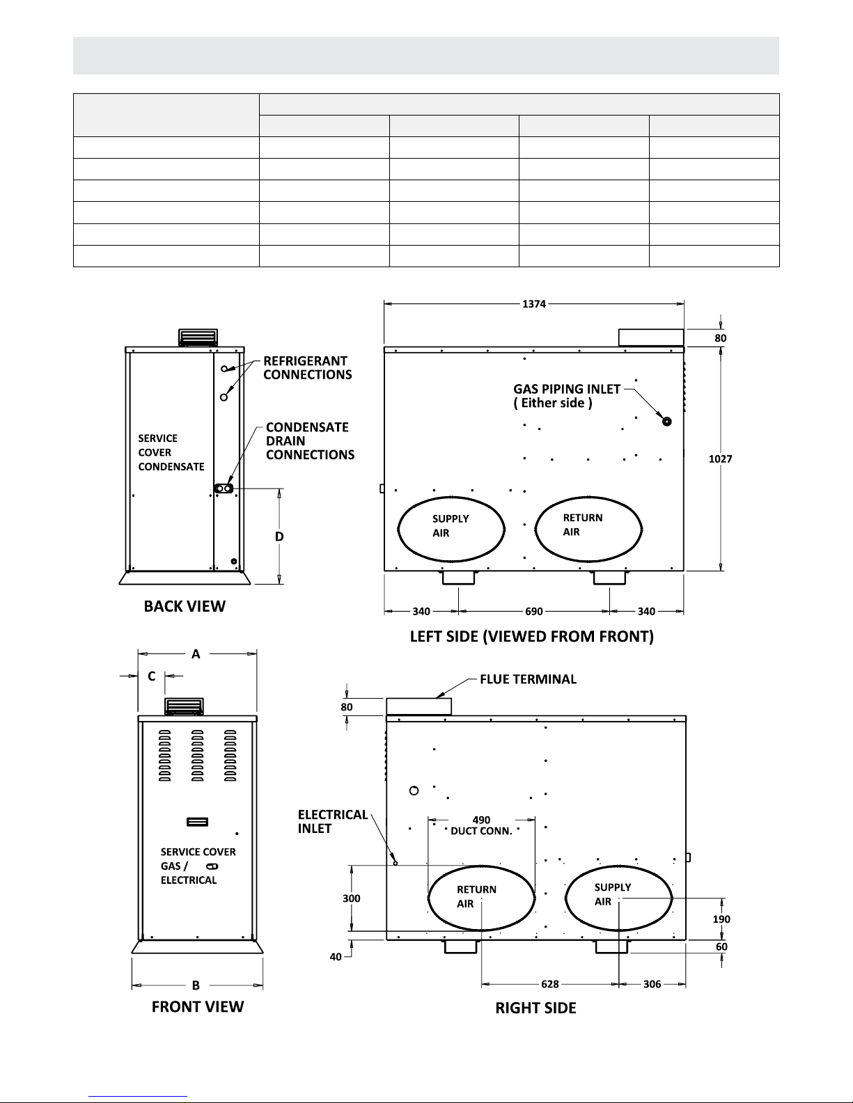
MODEL DIMENSIONS mm
A B C D
ML18007036A-E 456 512 80 -
ML18007036A-EC 456 512 80 533
ML18011060C-E 544 600 123 -
ML18011060C-EC 544 600 123 438
ML18013560D-E 633 690 167 -
ML18013560D-EC 633 690 167 438
LENNOX MERIT SERIES™ FURNACE SPECIFICATIONS
NOTE: DUCT CONNECTIONS ARE INTERCHANGEABLE FROM SIDE TO SIDE
Page 3

3
LENNOX MERIT SERIES™ GAS FURNACE
SHIPPING AND PACKING LIST
REQUIREMENTS
The Lennox Merit Series™ unit is shipped ready for
installation for external applications.
Package 1 of 1 contains:
1 x Assembled Lennox Merit Series
™
unit
1 x Bag assembly containing the following:
2 x Screws
1 x Snap bushing
1 x Snap plug
1 x Wire tie
1 x Vent warning label
1 x Owner’s manual
1 x Bag assembly containing the following:
1 x 2.5m Power cord
The following items may be ordered separately:
1 x Thermostat
1 x Propane/LP changeover kit
1 x High altitude kit
Check equipment for shipping damage. If you nd any
damage, immediately contact the last carrier.
The Lennox Merit Series
™
furnace is approved for
installation for outside of building, with clearances as listed
in Figure 6. (Accessibility and service clearances must take
precedence over re protection clearances). Installation of
Lennox forced air central furnaces must be in accordance
with these instructions, local gas tting regulations,
municipal building codes, electrical wiring regulations and
the current edition of the Australian Gas Installation Code
(AS5601).
Adequate clearance must be made around the air openings
into the vestibule area. Provisions shall be made for proper
operation and for combustion air and ventilation air supply
according to the current edition of the Australian Gas
Installation Code (AS5601).
NOTE: For installation on combustible oors, the furnace
shall not be installed directly on carpeting, tile, or other
combustible material other than wood ooring.
For installation in a residential garage, the furnace must be
installed so that the burner(s) and the ignition source are
located no less than 457 mm (18 in) above the oor.
The furnace must be located or protected to avoid physical
damage by vehicles. When a furnace is installed in a public
garage, hangar, or other building that has a hazardous
atmosphere, the furnace must be installed according to
recommended good practice requirements and current
edition of the Australian Gas Installation Code (AS5601).
Unit must be adjusted to obtain a temperature rise within
the range specied on appliance rating plate. This Lennox
Merit Series
™
furnace must be installed so that its electrical
components are protected from water.
When this furnace is used with cooling units, it shall be
installed in parallel with, or on the upstream side of, cooling
units to avoid condensation in the heating compartment.
With a parallel ow arrangement, a damper (or other means
to control the ow of air) must adequately prevent chilled
air from entering the furnace. If the damper is manually
operated, it must be equipped to prevent operation of either
the heating or the cooling unit, unless it is in the full HEAT or
COOL setting.
When installed, this furnace must be electrically
grounded according to local codes.
All eld wiring must comply with the current edition
of Australian Standard AS3000.
The blower access panel must be securely
in place when the blower and burners are
operating. Gas fumes, which could contain
carbon monoxide, can be drawn into living
space resulting in personal injury or death.
WARNING
!
Page 4

4
GENERAL GENERAL
LOCATION / PLACEMENT
These instructions are intended as a general guide and do
not supersede local codes in any way. Consult authorities
having jurisdiction before installation.
In addition to the requirements outlined previously, the
following general recommendations must be considered
when installing a Lennox Merit Series
™
furnace:
Place the furnace as close to the center of the air
distribution system as possible.
Do not block the furnace combustion air openings with
clothing, boxes, doors, etc. Air is needed for proper
combustion and safe unit operation.
These instructions are intended as a general guide and
do not supersede local codes in any way. Consult AGA.
AG-601 INSTALLATION CODE or authorities having
jurisdiction before installation.
The Lennox Merit Series
™
furnace is approved for
installation outside the building only with clearances as listed
in Table 1.
Installation of Lennox outdoor central furnaces must be
in accordance with these instructions, local gas tting
regulations, municipal building codes, electrical wiring
regulations and the current edition of the Australian Gas
Installation Code (AG 601).
The following general recommendations should be considered
when installing the Lennox Merit Series
™
Gas Furnace.
The Lennox Merit Series
™
Gas Furnace can be installed in
either right or left hand mode.
NOTE: On some models - 1/3 and 1/2 hp blower motors
are equipped with either four exible mounting legs or three
exible legs and one rigid leg. The rigid leg is equipped with
a shipping bolt and a at white plastic washer (rather than
the rubber mounting grommet used with a exible mounting
leg). This shipping bolt and at washer must be removed
before the furnace is put into operation. Once the shipping
bolt and washer are removed, the rigid leg will not touch the
fan housing.
Select a unit location that will allow for required clearances
per local AG 601 codes and in Table 1.
Also consider gas supply connections, electrical supply, vent
termination and installation and service clearances (600mm
front).
Accessibility and service clearances must not take
precedence over re protection clearances.
The Lennox Merit Series
™
Gas Furnace furnace should be
set on a eld-provided platform to keep the unit base out
of water. The unit is equipped with base rails, which lift the
bottom of the unit off of the platform. Unit must be levelled
using shims or levelling bolts. Knock-outs are provided in
unit base to install eld-provided levelling bolts.
Do not install the furnace in a corrosive
or contaminated atmosphere. Meet all
combustion and ventilation air requirements,
as well as all local codes.
CAUTION
!
SHIPPING AND PACKING LIST
Package 1 of 1 contains:
1 x Assembled unit
1 x Flue adapter/cowl eld–installed
2 x Starting collars
The following additional items may be ordered separately,
if required:
1 x Cooling coil
1 x Thermostat
1 x LP Changeover kit
Check unit for shipping damage. Receiving party should
contact last carrier immediately if any shipping damage is
found.
Page 5

5
DUCT SYSTEM
INSTALLING OPTIONAL
COOLING COIL
The unit is provided with knock-outs for either right or leftside connection of the supply and return air plenums.
Refer to the dimensioned drawing on page 2 to locate and
size the plenum entry into the side of the building.
Cover plates are provided to seal the unused knock-outs and
these become convenient access ports for regular service
and maintenance.
Size and install supply and return air duct system using
industry-approved standards that result in a quiet and
low-static system with uniform air distribution. The furnace
access panel must always be in place when the unit is in
operation and it must not allow leaks into the duct system.
Construct a protective covering made of suitable materials to
shield the plenum connections from rain. Rain shield should
be attached to the side of the unit cabinet above the plenum
connections and span the distance to the building wall above
the plenum entry into the structure. Rain shield connections
must be caulked so that they are weather-tight.
If optional cooling coil is to be used, install coil according to
the steps indicated below:
1. Remove Lennox Merit Series
™
Gas Furnace unit rear
panel.
NOTE: Installation of larger evaporator coils may require
removal of unit top panel as well.
2. Place cooling coil on unit coil deck in cooling
compartment.
3. Using template provided with the coil, cut holes for
refrigeration and drain piping. Align coil with piping holes
in panel. Seal holes around piping.
4. Reinstall Lennox Merit Series
™
panel.
5. Make refrigerant piping connections to condensing unit
per local codes and sound plumbing practices.
Page 6
6
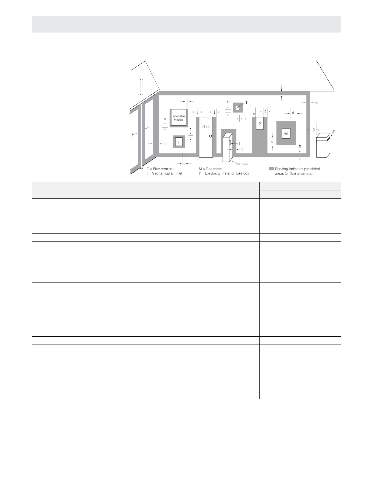
Ref. Item
Minimum clearances mm
Natural draft Fan assisted
A Below eaves, balconies and other projections:
• Appliances up to 50 Mj/h input
• Appliances over 50 Mj/h input
300
500
200
300
B From the ground, above a balcony or other surface* 300 300
C From a return wall or external corner* 500 300
D From a gas meter (M) (see 4.7.11 for vent terminal location of regulator) 1000 1000
E From an electricity meter or fuse box (P) 500 500
F From a drain pipe or soil pipe 150 75
G Horizontally from any building structure* or obstruction facing a terminal 500 500
H From any other ue terminal, cowl, or combustion air intake* 500 300
J Horizontally from an openable window, door, non-mechanical air inlet, or any other
opening into a building with the exception of sub-oor ventilation:
• Appliances up to 150 Mj/h input
• Appliances over 150 Mj/h input up to 200 Mj/h input
• Appliances over 200 Mj/h input
• All fan-assisted ue appliances, in the direction of discharge
500
1500
1500
1500
300
500
1500
K From a mechanical air inlet, including a spa blower 1500 1000
N Vertically below an openable window, non-mechanical air inlet, or any other opening
into a building with the exception of sub-oor ventilation:
• Space heaters up to 50 Mj/h input
• Other appliances up to 50 Mj/h input
• Appliances over 50 Mj/h input and up to 150 Mj/h input
• Appliances over 150Mj/h input
150
500
1000
1500
150
500
1000
1500
*Unless appliance is approved for closer installation
NOTES:
1. All distances are measured to the nearest part of the terminal.
2. Prohibited area below electricity meter or fuse box extends to
ground level.
3. See Clause 5.13.6.6 for restrictions on a ue terminal under a
covered area.
4. See Appendix J, Figures J2(a) and J3(a), for clearances required from a
ue terminal to an LP Gas cylinder. A ue terminal is considered to be a
source of ignition.
5. For appliances not addressed above, approval shall be obtained from
the Authority.
Figure 1
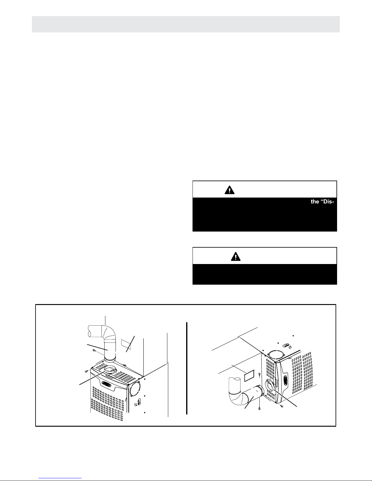
VENTING
The Lennox Merit Series™ unit is shipped standard for top ue discharge. A ue adapter is supplied with the furnace. It must
be installed on the outside of the furnace.
FLUE TERMINATION
CLEARANCES
Page 7
7
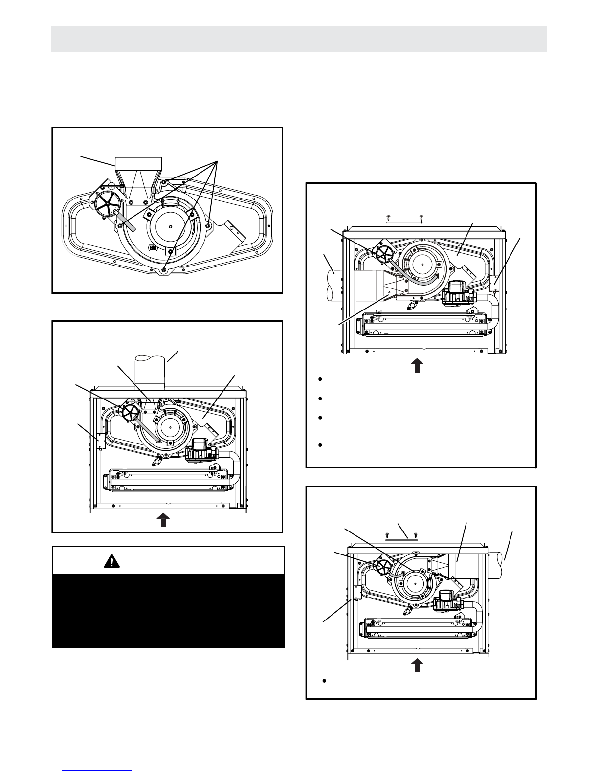
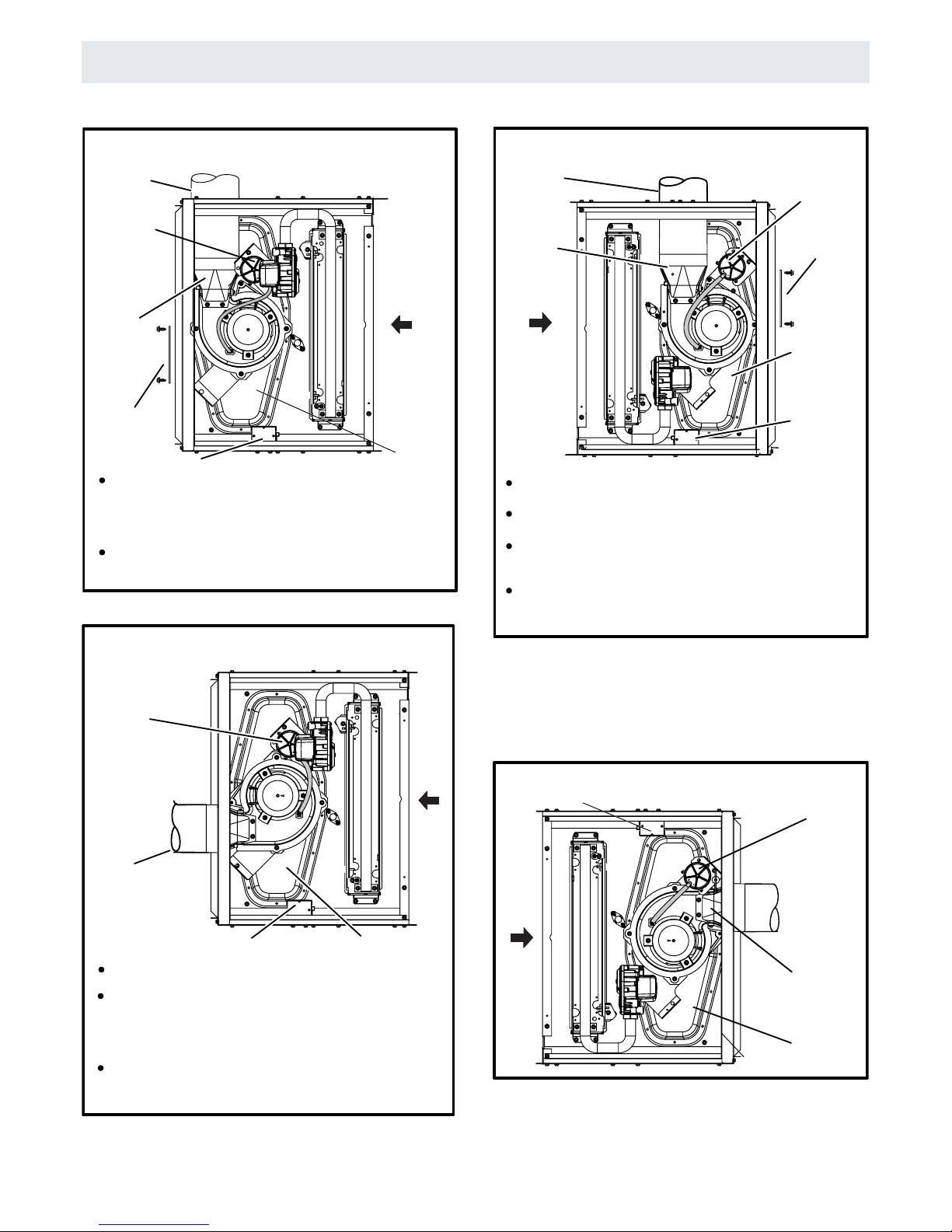
VENTING
A 4−inch diameter ue transition is factory-inst
alled on the
combustion
air inducer outlet of all models. Figure 3
shows
the combustion air inducer as shipped from the
factor
y.
FIGURE 2
Mounting Screws Location
Mounting Screws
Flue Transition
Upow Position
FIGURE 3
UPFLOW POSITION
Top Vent Discharge
FLOW
AIR
Collector Box
Vent Pipe
Flue
Transition
Pressure
Switch
Make−Up
Box
IMPORTANT
The unit will not vent properly with the ue transition
pointed down in the 6 o’clock position.
The combustion air inducer may be rotated clockwise or counterclockwise by 90° to allow for top or
side vent discharge in all applications. When the unit
is installed, the ue transition must be in the 9
o’clock, 12 o’clock or 3 o’clock position.
If
necessary, reposition the combustion air inducer, pres-
sure
switch and/or make−up box as needed per the follow-
ing
steps. See gures 3 through 9.
1 − Remove the four mounting screws (gure 2) which
secure the combustion air inducer / pressure switch
assembly to the orice plate. Lift the assembly and rotate it 90 degrees clockwise or counterclockwise to ei-
ther the 3 o’clock position or to 9 o’clock position. Re−
secure with four screws. Gasket should be left in place.
2 − Use tin snips to cut preferred opening on the cabinet
for repositioning the ue outlet. Use the cut−out piece
as a cover plate to patch unused opening on cabinet.
UPFLOW POSITION
Left Side Vent Discharge
FIGURE 4
Cut combustion air inducer tubing from 225mm to 125mm
to avoid
interference with inducer motor
Remove make−up box assembly (2 screws) and cut wire tie to
free make−up box wires. Re−install make−up box on other side
of cabinet.
Re−secure make−up box wires: Either pull excess wires
through the blower compartment and secure using supplied
wire tie, or coil excess wire and secure to the gas manifold.
FLOW
AIR
Make−Up
Box
Pressure
Switch
Flue
Transition
Vent Pipe
Collector Box
Gas supply piping must be brought into the unit from the right
side in order to accommodate the ue pipe.
UPFLOW POSITION
Right Side Vent Discharge
FIGURE 5
FLOW
AIR
Cover Plate
Flue Transition
Vent Pipe
Pressure
Switch
Make−Up
Box
Collector Box
Cut combustion air inducer tubing from 225mm to 125mm
to avoid
interference with inducer motor
Page 8
8
VENTING
HORIZONTAL LEFT POSITION
Top Vent Discharge
FIGURE 6
Disconnect pressure switch hose from barbed tting on the
pressure switch assembly. Remove pressure switch assembly
(1 screw) and cut wire tie to free pressure switch wires.
Re−
install pressure switch on the other side of orice plate and
re−connect pressure switch hose.
Re−secure pressure switch wires: Either pull excess wires
through the blower compartment and secure using supplied
wire tie, or coil excess wire and secure to the gas manifold.
Pressure
Switch
Vent Pipe
Flue
Transition
Cover Plate
Make−Up Box
Collector Box
FLOW
AIR
FIGURE 7
Make−Up Box
Collector Box
Vent Pipe
Pressure Switch
HORIZONTAL LEFT POSITION
Side Vent Discharge
Disconnect pressure switch hose from barbed tting on the
pressure switch assembly. Remove pressure switch assembly
(1 screw) and cut wire tie to free pressure switch wires. Re−
install pressure switch on the other side of orice plate and re−
connect pressure switch hose.
Re−secure pressure switch wires: Either pull excess wires
through the blower compartment and secure using supplied
wire tie, or coil excess wire and secure to the gas manifold.
FLOW
AIR
Cut combustion air inducer tubing from 225mm to 125mm
to avoid
interference with inducer motor
HORIZONTAL RIGHT POSITION
Top Vent Discharge
FIGURE 8
Remove make−up box assembly (2 screws) and cut wire tie to
free make−up box wires. Re−install make−up box on other side
of cabinet.
Re−secure make−up box wires: Either pull excess wires through
the blower compartment and secure using supplied wire tie, or
coil excess wire and secure to the gas manifold.
FLOW
AIR
Flue
Transition
Vent Pipe
Pressure Switch
Cover Plate
Make−Up Box
Collector Box
Gas supply piping must be brought into the unit from the bot-
tom in order to accommodate the ue pipe.
Cut combustion air inducer tubing from 225mm to 125mm
to avoid
interference with inducer motor
HORIZONTAL RIGHT POSITION
Side Vent Discharge
FIGURE 9
FLOW
AIR
Pressure Switch
Flue Transition
Collector Box
Make−Up Box
Page 9
9
VENTING
The Lennox Merit SeriesTM Gas Furnace units
are classied as fan−assisted
Category I furnaces
when vertically vented according to the latest edition
of National Fuel Gas Code (NFPA 54 / ANSI Z223.1)
in the USA. A fan−assisted Category I furnace is an
appliance equipped with an integral mechanical means
to either draw or force combustion products through the
combustion chamber and/or heat exchanger. The internal
unit is not approved for use with horizontal venting.
NOTE −
Use these instructions as a guide. They do not supersede local codes. This furnace must be vented according to all local codes these installation instructions, and the
provided venting tables in these instructions
The venting tables in this manual were extracted from the
National Fuel Gas Code (NFPA 54 / ANSI Z223.1) and are
provided as a guide for proper vent installation. Proper application, termination, construction and location of vents
must conform to local codes having jurisdiction.
of local codes, the NFGC serves as the
dening document.
Refer to the tables and the venting information contained in
these instructions to properly size and install the venting
system.
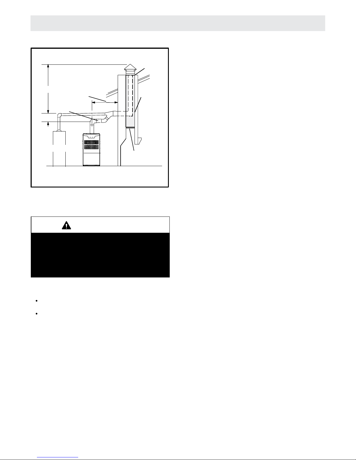
Use self−drilling sheet metal screws or a mechanical fastener to rmly secure the vent pipe to the round collar of the
ue transition. If self−drilling screws are used to attach the
vent pipe, it is recommended that three be used. Drive one
self−drilling screw through the front and one through each
side of the vent pipe and collar. See gure 10.
Install the rst vent connector elbow at a minimum of six
inches (152 mm) from the furnace vent outlet. See gure
10.
Venting Using a Masonry Chimney
The following additional requirements apply when a lined
masonry chimney is used to vent this furnace.
Masonry chimneys used to vent Category I central fur-
naces must be either tile-lined or lined with a listed metal
lining system or dedicated gas vent. Unlined masonry
chimneys are prohibited. See gures 11 and 12 for common venting.
A chimney with one or more sides exposed to the outside of
the structure is considered to be an exterior chimney.
An exterior masonry chimney that is not tile−lined must be
lined with B1 vent or a listed insulated exible metal vent.
An exterior tile−lined chimney that is sealed and
capped
may be lined with a listed uninsulated exible metal vent.
If the existing chimney will not accommodate a listed metal
liner, either the chimney must be rebuilt to accommodate
one of these liners or an alternate approved venting method must be found.
Insulation for the exible vent pipe must be an encapsulated berglass sleeve recommended by the exible vent
pipe manufacturer. See gure 11.
IMPORTANT
Once the venting system is installed, attach
connected Vent" warning sticker to a visible area of
the plenum near the vent pipe. See gure 10. The
warning sticker is provided in the bag assembly. Order kit 66W04 for additional stickers.
WARNING
Asphyxiation hazard. The exhaust vent for this furnace must be securely connected to the furnace ue
transition at all times.
FIGURE 10
FLUE TRANSITION
COLLAR
VENT PIPE
(min. 150mm length)
“DISCONNECTED VENT”
WARNING
STICKER
FLUE
TRANSITION
COLLAR
VENT CONNECTION UPFLOW AND HORIZONTAL POSITION
VENT PIPE
(min. 150mm length)
“DISCONNECTED VENT”
WARNING
STICKER
In the absence
Page 10
10
VENTING
FIGURE 11
Common Venting Using Metal−Lined Masonry Chimney
4 in. (102 mm)
minimum
MIN. LENGTH −− AS
SHORT AS PRACTICAL
MAX. LENGTH
−− SEE NOTE 1
BELOW.
SEALED
PERMANENTLY
SEALED FIREPLACE
OPENING
EXTERIOR
CHIMNEY WITH
METAL
LINER
VENT CONNECTOR
NOTE 1 − Refer to the provided venting tables for installations. Refer
to the capacity requirements shown in the provided venting tables.
OTHER
APPLIANCE
FURNACE
5 ft. (1.5 m)
minimum
DO
NOT insulate the space between the liner and the
chimne
y wall with puffed mica or any other loose gran-
ular insulating material.
IMPORTANT
SINGLE appliance venting of a fan-assisted furnace
into a tile-lined masonry chimney (interior or outside
wall) is PROHIBITED. The chimney must rst be lined
with either type B1 vent or an insulated single wall
exible vent lining system which has been sized according to the provided venting tables and the vent
pipe manufacturer’s instructions.
A
fan−assisted furnace may be commonly vented into an
existing
lined masonry chimney if the following conditions
are met:
The chimney is currently serving at least one draf thood−
equipped appliance;
The vent connectors and chimney are sized according
to the provided venting tables.
If
type B1 double-wall vent is used inside a chimney, no oth-
er appliance can be vented into the chimney
. The outer wall
of type B1 vent pipe must not be exposed to ue product
s.
A
type B1 vent or masonry chimney liner shall terminate
above the
roof surface with a listed cap or a listed roof as-
sembly
according to the terms of their respective listings
and the vent manufacturer’s instructions.
When inspection reveals that an existing chimney is not
safe for the intended purpose, it shall be rebuilt to conform
to nationally recognised standards, lined or relined with
suitable materials, or replaced with a gas vent or chimney
suitable for venting the units. The chimney
passageway
must be checked periodically to ensure that it is clear and
free of obstructions.
Do not install a manual damper, barometric draft regulator,
or ue restrictor between the furnace and the chimney.
Never connect a Category I appliance to a chimney that is
servicing a solid−fuel appliance. If a replace chimney ue
is used to vent this appliance, the replace opening must
be permanently sealed.
A type B or listed chimney lining system that passes
through an unused masonry chimney ue is not considered
to be exposed to the outdoors.
General Venting Requirements
Vent all internal furnaces according to these instructions:
1 −Vent diameter recommendations and maximum allow-
able piping runs are found in the provided venting
tables.
2 −In no case should the vent or vent connector diameter
be less than the diameter specied in the provided
venting tables.
3 −The minimum vent capacity determined by the sizing
tables must be less than the low re input rating and the
maximum vent capacity must be greater than the high
re input rating.
4 −Single appliance vents − If the vertical vent or tile-lined
chimney has a larger diameter or ow area than the
vent connector, use the vertical vent diameter to de-
termine the minimum vent capacity and the vent
connector diameter to determine the maximum vent
capacity. The ow area of the vertical vent, however,
shall not exceed 7 times the ow area of the listed appliance categorized vent area, drafthood outlet area or
ue collar area unless designed according to approved
engineering methods.
5 −Multiple appliance vents − The ow area of the largest
section of vertical vent or chimney shall not exceed 7
times the smallest listed appliance categorized vent
area, drafthood outlet area or ue collar area unless designed according to approved engineering methods.
Page 11

11
VENTING
FIGURE 12
Common Venting Using Tile−Lined Interior Masonry Chimney and Combined Vent Connector
MINIMUM LENGTH = AS SHORT AS PRACTICAL.
FOR MAXIMUM LENGTH SEE NOTE TO LEFT
INTERIOR TILE−LINED
MASONRY CHIMNEY
NOTE − the chimney must be properly
sized per provided venting tables or
lined with listed metal lining system.
PERMANENTLY
SEALED FIREPLACE
OPENING
VENT
CONNECTOR
NOTE− Refer to provided venting
tables for installations.
FURNACE
OTHER
APPLIANCE
6 −
The entire length of single wall metal vent connector
shall be readily accessible for inspection, cleaning,
and replacement.
7 −
Single appliance venting congurations with zero lateral
lengths are assumed to have no elbows in
the vent
system. For all other vent congurations, the vent
system is assumed to have two 90° elbows. For each
additional 90° elbow or equivalent (for example two
45° elbows equal one 90° elbow) beyond two, the
maximum capacity listed in the venting table should
be reduced by 10% (0.90 x maximum listed capacity).
8 −
The common venting tables (5, 6, 7, and 8) were gen-
erated using a maximum horizontal vent connector
length of 1−1/2 feet (.46 m) for each inch (25 mm) of
connector diameter as follows:
Connector Diameter
inches (mm)
Maximum Horizontal
Connector Length feet (m)
3 (76) 4−1/2 (1.37)
4 (102) 6 (1.83)
5 (127) 7−1/2 (2.29)
6 (152) 9 (2.74)
7 (178) 10−1/2 (3.20)
9 −
If the common vertical vent is offset, the maximum
common vent capacity listed in the common venting
tables should be reduced by 20%, the equivalent of two
90° elbows (0.80 x maximum common vent capacity).
The horizontal length of the offset shall not exceed
1-1/2 feet (.46 m) for each inch (25 mm) of common
vent diameter.
10 − The vent pipe should be as short as possible with the
least number of elbows and angles required to complete the job. Route the vent connector to the vent using the shortest possible route.
11 − A vent connector shall be supported without any di
ps
or sags and shall slope a minimum of 1/4 inch (6.4 mm)
per linear foot (305 mm) of connector, back toward the
appliance.
12 − Vent connectors shall be rmly attached to the furnace
ue collar by self−drilling screws or other approved
means, except vent connectors of listed type B vent
material which shall be assembled according to the
manufacturer’s instructions. Joints between sections
of single wall connector piping shall be fastened by
screws or other approved means.
13 − When the vent connector used for Category I ap-
pliances must be located in or pass through a crawlspace, attic or other areas which may be cold, that portion of the vent connector shall be constructed of listed
double-wall type B vent material or material having
equivalent insulation qualities.
14 − All venting pipe passing through oors, walls, and ceil-
ings must be installed with the listed clearance to combustible materials and be re stopped according to local codes. In absence of local codes, refer to NFGC
(Z223.1).
15 − No portion of the venting system can extend into, or pas
s
through any circulation air duct or plenum.
Page 12

12
VENTING
16 −Vent connectors serving Category I appliances shall
not be connected to any portion of mechanical draft
systems operating under positive pressure such as
Category III or IV venting systems.
1
7 − If vent connectors are combined prior to entering the
common vent, the maximum common vent capacity
listed in the common venting tables must be reduced by
10%, the equivalent of one 90° elbow (0.90 x maximum
common vent capacity).
18 −
The common vent diameter must always be at least as
large as the largest vent connector diameter.
19 −
In no case, shall the vent connector be sized more than
two consecutive table size diameters over the size of
the draft hood outlet or ue collar outlet.
20 − Do not install a manual damper,
barometric draft regu-
lator or ue restrictor between the furnace and the
chimney.
21 − When connecting this appliance to an existing dedi
-
cated or common venting system, you must inspect the
venting system’s general condition and look for signs
of corrosion. The existing vent pipe size must conform
to these instructions and the provided venting tables. If
the existing venting system does not meet these requirements, it must be resized.
Capacity of Type B Double−Wall Vents with Type B Double−Wall Connectors
Serving a Single Category I Appliance
Height
H
(m) (m)
Lateral
L
Vent and Connector Diameter − D (mm)
76mm 100mm 125mm 150mm
Appliance Input Rating in Thousands of Btu Per Hour
MIN MAX MIN MAX MIN MAX MIN MAX
1.8
2.4
4.5
3.0
6.0
9.0
0 0 78 0 152 0 251 0 375
0.6 13 51 18 97 27 157 32 232
1.2 21 49 30 94 39 153 50 227
1.8 25 46 36 91 47 149 59 223
0 0 84 0 165 0 276 0 415
0.6 12 57 16 109 25 178 28 263
1.5 23 53 32 103 42 171 53 255
2.4 28 49 39 98 51 164 64 247
0
0 88 0 175 0 295 0 447
0.6 12 61 17 118 23 194 26 289
1.5 23 57 32 113 41 187 52 280
3.0 30 51 41 104 54 176 67 267
0
0 94 0 191 0 327 0 502
0.6 11 69 15 136 20 226 22 339
1.5 22 65 30 130 39 219 49 330
3.0 29 59 40 121 51 206 64 315
4.5 35 53 48 11 2 61 195 76 301
0
0 97 0 202 0 349 0 540
0.6 10 75 14 149 18 250 20 377
1.5 21 71 29 143 38 242 47 367
3.0 28 64 38 133 50 229 62 351
4.5 34 58 46 124 59 217 73 337
6.0 48 52 55 116 69 206 84 322
0
0 100 0 213 0 374 0 587
0.6 9 81 13 166 14 283 18 432
1.5 21 77 28 160 36 275 45 421
3.0 27 70 37 150 48 262 59 405
4.5 33 64 44 141 57 249 70 389
6.0 56 58 53 132 66 237 80 374
9.0 NA NA 73 113 88 214 104 346
NOTE − Single appliance venting congurations with zero lateral lengths are assumed to have no elbows in the vent system. For all other
vent congurations, the vent system is assumed to have two 90° elbows. For each additional 90° elbow or equivalent (for example two 45°
elbows equal one 90° elbow) beyond two, the maximum capacity listed in the venting table should be reduced by 10 percent (0.90 x maxi-
mum listed capacity).
Page 13

13
VENTING
Capacity of Type B Double−Wall Vents with Single−Wall Metal Connectors
Serving a Single Category I Appliance
Height
H
(m)(m)
Lateral
L
Vent and Connector Diameter − D (mm)
76mm 100mm 125mm 150mm
Appliance Input Rating in Thousands of Btu Per Hour
MIN MAX MIN MAX MIN MAX MIN MAX
1.8
2.4
6.0
9.0
4.5
3.0
0 38 77 59 151 85 249 126 373
0.6 39 51 60 96 85 156 123 231
1.2 NA NA 74 92 102 152 146 225
1.8
0
0.6
1.5
2.4
0
0.6
1.5
3.0
0
0.6
1.5
3.0
4.5
0
0.6
1.5
3.0
4.5
6.0
0
0.6
1.5
3.0
4.5
6.0
9.0
NA NA 83 89 11 4 147 163 220
37 83 58 164 83 273 123 412
39 56 59 108 83 176 121 261
NA NA 77 102 107 168 151 252
NA NA 90 95 122 161 175 243
37 87 57 174 82 293 120 444
39 61 59 11 7 82 193 119 287
52 56 76 111 105 185 148 277
NA NA 97 100 132 171 188 261
36 93 56 190 80 325 116 499
38 69 57 136 80 225 115 337
51 63 75 128 102 216 144 326
NA NA 95 116 128 201 182 308
NA NA NA NA 158 186 220 290
35 96 54 200 78 346 114 537
37 74 56 148 78 248 113 375
50 68 73 140 100 239 141 363
NA NA 93 129 125 223 177 344
NA NA NA NA 155 208 216 325
NA NA NA NA 186 192 254 306
34 99 53 211 76 372 110 584
37 80 55 164 76 281 109 429
49 74 72 157 98 271 136 417
NA NA 91 144 122 255 171 397
NA NA 115 131 151 239 208 377
NA NA NA NA 181 223 246 357
NA NA NA NA NA NA NA NA
NOTE − S
ingle appliance venting congurations with zero lateral lengths are assumed to have no elbows in the vent system. For all other
vent congurations, the vent system is assumed to have two 90° elbows. For each additional 90° elbow or equivalent (for example two 45°
elbows equal one 90° elbow) beyond two, the maximum capacity listed in the venting ta
ble should be reduced by 10 percent (0.90 x maxi-
mum listed capacity).
Page 14

14
VENTING
Vent Connector Capacity
Type B Double−Wall Vents with Type B Double−Wall Connectors
Serving Two or More Category I Appliances
Vent
Height
H
(m)
Connector
Rise
R
(m)
Vent and Connector Diameter − D (mm)
25mm 50mm 125mm 150mm
Appliance Input Rating in Thousands of Btu Per Hour
MIN MAX MIN MAX MIN MAX MIN MAX
1.8
1
22 37 35 66 46 106 58 164
0.6 23 41 37 75 48 121 60 183
0.9 24 44 38 81 49 132 62 199
2.4
22 40 35 72 49 11 4 64 176
23 44 36 80 51 128 66 195
24 47 37 87 53 139 67 210
3.0
22 43 34 78 49 123 65 189
23 47 36 86 51 136 67 206
24 50 37 92 52 146 69 220
4.5
21 50 33 89 47 142 64 220
22 53 35 96 49 153 66 235
24 55 36 102 51 163 68 248
6.0
21 54 33 99 46 157 62 246
22 57 34 105 48 167 64 259
23 60 35 11 0 50 176 66 271
9.0
20 62 31 11 3 45 181 60 288
21 64 33 11 8 47 190 62 299
22 66 34 123 48 198 64 309
Common Vent Capacity
Type B Double−Wall Vents with Type B Double−Wall Connectors
Serving Two or More Category I Appliances
Vent
Height
H
(m)
Common Vent Diameter − D (mm)
100mm 125mm 150mm 175mm
Appliance Input Rating in Thousands of Btu Per Hour
FAN + FAN FAN + NAT FAN + FAN FAN + NAT FAN + FAN FAN + NAT FAN + FAN FAN + NAT
1.8 92 81 140 11 6 204 161 309 248
2.4 101 90 155 129 224 178 339 275
3.0 11 0 97 169 141 243 194 367 299
4.5 125 11 2 195 164 283 228 427 352
6.0 136 123 215 183 314 255 475 394
9.0 152 138 244 210 361 297 547 459
1
0.6
0.9
1
0.6
0.9
1
0.6
0.9
1
0.6
0.9
1
0.6
0.9
Page 15

15
VENTING
Vent Connector Capacity
Type B Double−Wall Vents with Single−Wall Metal Connectors
Serving Two or More Category I Appliances
Height
H
(m)
Lateral
L
(m)
Vent and Connector Diameter − D (mm)
76mm 100mm 125mm 150mm
Appliance Input Rating in Thousands of Btu Per Hour
MIN MAX MIN MAX MIN MAX MIN MAX
1.8
1 NA NA NA NA NA NA NA NA
0.6
NA NA NA NA NA NA 168 182
0.9
NA NA NA NA 121 131 175 198
2.4
1
NA NA NA NA NA NA NA NA
0.6
NA NA NA NA 125 126 184 193
0.9
NA NA NA NA 130 138 191 208
3.0
1
NA NA NA NA 119 121 182 186
0.6
NA NA 84 85 124 134 189 203
0.9
NA NA 89 91 129 144 197 217
4.5
1
NA NA 79 87 116 138 177 214
0.6
NA NA 83 94 121 150 185 230
0.9
NA NA 87 100 127 160 193 243
6.0
1
49 56 78 97 115 152 175 238
0.6
52 59 82 103 120 163 182 252
0.9
55 62 87 107 125 172 190 264
9.0
1
47 60 77 110 112 175 169 278
0.6
51 62 81 115 117 185 177 290
0.9
54 64 85 119 122 193 185 300
NOTE − Single appliance venting congurations with zero lateral lengths
are assumed to have no elbows in the vent system. For all other
vent congurations, the vent system is assumed to have two 90° elbows. For each additional 90° elbow or equivalent (for example two 45°
elbows equal one 90° elbow) beyond two, the maximum capacity listed in the venting table should be reduced by 10 percent (0.90 x maxi
-
mum listed capacity).
Common Vent Capacity
Type B Double−Wall Vents with Single−Wall Metal Connectors
Serving Two or More Category I Appliances
Vent
Height
H
(m)
Common Vent Diameter − D (mm)
100mm 125mm 150mm 175mm
Appliance Input Rating in Thousands of Btu Per Hour
FAN + FAN FA N + NAT FAN + FA N FA N + NAT FAN + FAN FAN + NAT FA N + FAN FAN + NAT
1.8
NA 78 NA 113 200 158 304 244
2.4
NA 87 NA 126 218 173 331 269
3.0
NA 94 163 137 237 189 357 292
4.5
121 108 189 159 275 221 416 343
6.0
131 118 208 177 305 247 463 383
9.0 145 132 236 202 350 286 533 446
Page 16

16
VENTING
Removal of the Furnace from Common Vent
In the event that an existing furnace is removed from a
venting system commonly run with separate gas appliances, the venting system is likely to be too large to
properly vent the remaining attached appliances.
Conduct the following test while each appliance is operating and the other appliances (which are not operating) remain connected to the common venting system. If the
venting system has been installed improperly, you must
correct the system as indicated in the general venting requirements section.
WARNING
CARBON MONOXIDE POISONING HAZARD
Failure to follow the steps outlined below for each
appliance connected to the venting system being
placed into operation could result in carbon monoxide poisoning or death.
The following steps shall be followed for each appliance connected to the venting system being
placed into operation, while all other appliances
connected to the venting system are not in
operation:
1 −
Seal any unused openings in the common venting sys-
tem.
2
−Inspect the venting system for proper size and horizontal
pitch. Determine that there is no blockage, restriction,
leakage, corrosion, or other deciencies which could
cause an unsafe condition.
3 − Close all building doors and windows and all doors be-
tween the space in which the appliances remaining
connected to the common venting system are located
and other spaces of the building. Turn on clothes dryers and any appliances not connected to the common
venting system. Turn on any exhaust fans, such as
range hoods and bathroom exhausts, so they will operate at maximum speed. Do not operate a summer exhaust fan. Close replace dampers.
4 −Follow the lighting instructions. Turn on the appliance
that is being inspected. Adjust the thermostat so that
the appliance operates continuously.
5 −After the burner have operated for 5 minutes, test for
leaks of ue gases at the draft hood relief opening. Use
the ame of a match or candle.
6 −After determining that each appliance connected to th
e
common venting system is venting properly, (step 3)
return all doors, widows, exhaust fans, replace dampers, and any other gas−burning appliances to their previous mode of operation.
7 −If a venting problem is found during any of the preced-
ing tests, the common venting system must be modied to correct the problem.
Resize the common venting system to the minimum
vent pipe size determined by using the appropriate
tables in Appendix G. (These are in the current standards of the National Fuel Gas Code ANSI Z223.1.
Page 17

17
GENERAL E OR EC SERIES
GAS PIPING
THERMOSTAT INSTALLATION
Install a room thermostat according to the instructions
furnished with it. Select a location on an inside wall and not
subject to drafts, direct sunshine or other heat sources. The
initial heat anticipator setting should be equal to the total
current draw of the control circuit.
FURNACE CHECK-OUT
Before leaving, the installer should make the following
checks to ensure that the controls are functioning properly.
CHECKING AND ADJUSTING GAS INPUT
The minimum permissible gas supply pressure for the purpose
of input adjustment is listed on table 4 of this manual.
GAS PRESSURE REGULATOR
Gas input must never exceed the value shown on the
furnace rating plate.
The manifold pressure can be measured by connecting
a water manometer or gauge to the pressure tap in the
downstream side of the gas valve.
Only small variations in gas input may be made by adjusting
the regulator. In no case should the nal manifold pressure
vary more than 0.3 in. W.C. (0.07kPa) from the above
specied pressures.
TEMPERATURE RISE
Check the temperature rise and, if necessary, adjust blower
speed to maintain temperature rise within the range shown
on the unit rating plate.
GAS SUPPLY
This unit is to be installed by a licensed gas
plumber fully in accordance with AG601 installation
regulations.
1. This unit is shipped standard for centre installation of gas
piping. Piping can be converted for right-side connection.
Simply connect gas supply to piping assembly.
2. When connecting gas supply, factors such as length
of run, number of ttings and furnace rating must
be considered to avoid excessive pressure drop. Unit
connection at gas manifold is 1/2 in. (12mm). Size piping
according to gas regulations.
3. Gas piping must not run in or through air ducts, clothes
chutes, chimneys or gas vents, dumb waiters or elevator
shafts.
4. Piping should be sloped 6mm per 380mm upward toward
the meter from the furnace. The piping must be supported
at proper intervals (2m) using suitable hangers or straps.
5. In some localities, codes may require installation of a
manual main shut-off valve and union (furnished by
installer) external to the unit. Union must be of the ground
joint type.
Compounds used on threaded joints of gas
piping must be resistant to the actions of
liquied petroleum gases.
IMPORTANT
!
Some soaps used for leak detection are
corrosive to certain metals. Carefully rinse piping
thoroughly after leak test has been completed.
Do not use matches, candles, ame or other
sources of ignition to check for gas leaks.
CAUTION
!
NOTE: Installer must provide a 3mm N.P.T. plugged tap in
the eld piping upstream of the gas supply connection to the
unit. Tap must be accessible for test gauge connection. This
requirement is negated if the gas valve in the unit is tted
with an integral pressure tapping point.
NOTE: If emergency shut-off is required, shut off main
manual gas valve and disconnect main power to unit. These
devices should be properly labelled by the installer.
LEAK CHECK
After gas piping has been completed, carefully check all
piping connections (factory and eld) for gas leaks. Use a
leak detecting solution or other preferred means.
The furnace must be isolated from the gas supply system
by closing its individual manual shut-off valve during any
pressure testing of the gas supply system at pressures equal
to or less than 1/2 psig (3.48 kPa).
Page 18

18
4. Install a separate disconnect switch (protected by either
fuse or circuit breaker) near the unit so power can be
turned off for servicing.
5. Before connecting thermostat or power wiring, check
to make sure wires will be long enough to facilitate
servicing at a later date. Remove blower access panel
and swing panel to check wire length for access.
6. Complete wiring connections to equipment using wiring
diagrams provided with unit and in eld wiring diagrams
shown in gures 5. Use 18 gauge wire or larger for
thermostat connections.
7. Electrically ground unit in accordance with local codes.
8. Three 240 volt accessory terminals are provided on the
control board. Two are energised with the indoor blower
and one is energised with the combustion air blower. Any
accessory rated up to one amp can be connected to the
accessory terminals with the neutral leg of the circuit
connected to the 240 volt neutral wires.
9. This unit is equipped with an integrated control board
that controls blower operation, fan off timings (EGC Board
0nly) and ignition. The board includes a terminal strip for
thermostat connections and two diagnostic LEDs. See
gure 6 for control board conguration. Diagnostic codes
are given in a chart at the back of this manual.
The red diagnostic button can be used to view the last
failure code. (EGC Ignition Board Only)
10.Refer to blower speed chart on wiring diagrams for
factory set cooling, heating and continuous fan speeds.
Systems using a cooling thermostat sub-base may
operate the blower continuously (factory set at low speed)
through the thermostat “FAN ON” switch. Systems, which
do not include a cooling sub-base require a toggle switch
which must be wired between terminals “R” and “G” on
the thermostat connection terminal strip. The blower
motor will operate at the designated speed during cooling
or heating demand; however, when demand is satised,
blower speed will revert to selected continuous speed.
When testing pressure of gas lines, gas valve
must be disconnected and isolated. See Figure 13.
Gas valves can be damaged if subjected to more
than 1/2 psig (3.48 kPa).
IMPORTANT
!
Electrostatic discharge can affect electronic
components. Take precautions during
furnace installation and service to protect the
furnace’s electronic controls. Precautions will
help to avoid control exposure to electrostatic
discharge by putting the furnace, the control
and the technician at the same electrostatic
potential. Neutralise electrostatic charge by
touching hand and all tools on an unpainted
unit surface, such as the gas valve or
blower deck, before performing any service
procedure.
CAUTION
!
MANUAL MAIN
SHUT-OFF VALV
E
WILL NOT HOLD
NORMAL TEST
PRESSURE
CAP
GAS VALVE
FURNACE
Figure 13
ELECTRICAL
ELECTROSTATIC DISCHARGE (ESD)
Precautions and Procedures
These units operate on 240 volt, single phase, 50Hz
electrical power. Refer to gure 14 for eld wiring and
Figure 16 for schematic wiring diagram and troubleshooting.
1. Select circuit protection and wire size according to
requirements listed on unit rating plate.
2. Snap-hole plugs are provided on both sides of cabinet to
facilitate wiring.
3. Install room thermostat according to instructions provided
with thermostat.
Page 19

19
The blower access panel must be securely
in place when the blower and burners are
operating. Gas fumes, which could contain
carbon monoxide, can be drawn into living
space resulting in personal injury or death.
WARNING
!
If a exible gas connector is required or
allowed by the authority that has jurisdiction,
black iron pipe shall be installed at the gas
valve and extend outside the furnace cabinet.
The exible connector can then be added
between the black iron pipe and the gas
supply line.
CAUTION
!
FILTERS
DUCT SYSTEM
GAS PIPING
VENTING
This unit is not equipped with a lter or rack. A eld-provided
high-velocity lter is required for the unit to operate properly.
Table 2 lists recommended lter sizes. A lter must be in
place any time the unit is operating.
TABLE 2
Furnace
Cabinet Width
Filter Size mm (in) and Quantity
Side Return Bottom Return
A - 338
(14-1/2”)
406 X 635 X 25 1
(16 X 25 X 1)
356 X 635 X 25 1
(14 X 25 X 1)
B- 446
(17-1/2”)
406 X 635 X 25 1
(16 X 25 X 1)
406 X 635 X 25 1
(16 X 25 X 1)
C - 533
( 21”)
405 X 635 X 25 1
(16 X 25 X 1)
508 X 635 X 25 1
(20 X 25 X 1)
D - 622
(24-1/2”)
405 X 635 X 25 2
(16 X 25 X 1)
610 X 635 X 25 1
(24 X 25 X 1)
Use industry approved standards (such as those published
by Air Conditioning Contractors of America or American
Society of Heating, Refrigerating and Air Conditioning
Engineers) to size and install the supply and return air duct
system. This will result in a quiet and low static system that
has uniform air distribution.
Refer to the current edition of the Australian Gas
Installation Code (AG601, ES5601) for gas piping
requirements and gas pipe sizing tables.
Gas supply piping should not allow more than 125 Pa
(0.5”W.C.) drop in pressure between gas meter and unit.
Supply gas pipe must not be smaller than unit gas
connection.
The Lennox Merit Series
™
Gas Furnace is a fan-assisted
furnace equipped with an integral mechanical means to
either draw or force products of combustion through the
combustion chamber and/or heat exchanger. When installed
in the vertical position and vented vertically, the furnace
operates with a non-positive vent stack pressure. When
installed in the horizontal position and vented vertically, the
furnace operates with a positive stack pressure.
GAS SUPPLY
1. This unit is shipped standard for left or right side
installation of gas piping (or top entry in horizontal
applications). Connect the gas supply to the piping
assembly.
2. When connecting the gas supply piping, consider factors
such as length of run, number of ttings, and furnace
rating to avoid excessive pressure drop.
3. The gas piping must not run in or through air ducts,
clothes chutes, gas vents or chimneys, dumb waiters, or
elevator shafts.
4. The piping should be sloped 6.4mm (1/4 in) per 4.57m
(15 ft.) upward toward the meter from the furnace. The
piping must be supported at proper intervals every 2.44
to 3.01m (8 to 10ft) with suitable hangers or straps.
Install a drip leg in vertical pipe runs to the unit.
5. A 3 mm (1/8”) N.P.T. plugged tap or pressure port is
located on the gas valve to facilitate test gauge connection.
6. In some localities, codes may require the installation of a
manual main shut off valve and union (furnished by the
installer) external to the unit. The union must be of the
ground joint type.
Page 20

20
Compounds used on threaded joints of gas
piping must be resistant to the actions of
liquied petroleum gases.
IMPORTANT
!
NOTE: If emergency shut-off is necessary, shut off the main
manual gas valve and disconnect main power to the furnace.
The installer should properly label these devices.
GROUND
JOINT
UNION
AUTOMATIC
GAS VALVE
FIELD
PROVIDED
AND INSTALLED
GROUND
JOINT
UNION
Left Side Piping
(Standard)
Right Side Piping
(Alternate)
AUTOMATIC
GAS VALVE
DRIP LEG
DRIP LEG
MANUAL
MAIN SHUT-OFF
VALVE
(With 3mm NPT
Plugged Tap Shown)
MANUAL
MAIN SHUT-OFF
VALVE
(With 3mm NPT
Plugged Tap
Shown)
NOTE - BLACK IRON PIPE ONLY TO BE ROUTED INSIDE OF CABINET
GROUND
JOINT
UNION
DRIP LEG
MANUAL
MAIN SHUT-OFF
VALVE
GROUND
JOINT
UNION
DRIP LEG
MANUAL
MAIN
SHUT-OFF
VALVE
GROUND
JOINT
UNION
DRIP LEG
MANUAL
MAIN SHUT-OFF
VALVE
Horizontal Application
Left-Side Air Discharge
Horizontal Application
Right-Side Air Discharge
NOTE - BLACK IRON PIPE ONLY TO BE ROUTED INSIDE OF CABINET
FIELD
PROVIDED
AND INSTALLED
Figure 14
Figure 15
Page 21

21
LEAK CHECK
After gas piping is completed, carefully check all piping
connections (factory- and eld-installed) for gas leaks. Use a
leak detecting solution or other preferred means.
NOTE: If emergency shut-off is necessary, shut off the main
manual gas valve and disconnect the main power to the
furnace. The installer should properly label these devices.
Some soaps used for leak detection are
corrosive to certain metals. Carefully rinse
piping thoroughly after leak test has been
completed. Do not use matches, candles,
ame or other sources of ignition to check for
gas leaks.
CAUTION
!
Electrostatic discharge can affect electronic
components. Take precautions to neutralise
electrostatic charge by touching your hand
and tools to metal prior to handling the
control.
CAUTION
!
When testing pressure of gas lines, gas valve
must be disconnected and isolated. See gure
24. Gas valves can be damaged if subjected to
pressures greater than 1/2 psig (3.48 kPa, 14
inches w.c.).
IMPORTANT
!
The furnace must be isolated by closing its individual manual
shut off valve and disconnecting from the gas supply system
the during any pressure testing of the gas supply system at
pressures greater than 1/2 psig (3.48kPa, 14 inches w.c.).
MANUAL MAIN
SHUT-OFF VALVE
WILL NOT HOLD
NORMAL TEST
PRESSURE
CAP
ISOLATE
GAS VALVE
FURNACE
1/8 NPT PLUG
Figure 16
ELECTRICAL
A power wiring harness is shipped with each Lennox Merit
Series™ furnace. An IEC receptacle is provided on the right
side of the unit. Plug the harness into the IEC receptacle and
into a properly sized wall plug.
Refer to gure 18 schematic wiring diagram.
1. Ensure that power connection point is located with 2m of
furnace.
2. Holes are on both sides of the furnace cabinet to facilitate
thermostat wiring.
3. Before connecting the thermostat wiring, check to make
sure the wires will be long enough for servicing at a
later date. Remove the blower access panel to check the
length of the wire.
4. Complete the wiring connections to the equipment. Use
the provided unit wiring diagram shown in Figure 18.
18-gauge wire or larger that is suitable for Class II rating
for thermostat connections.
5. Electrically ground the unit according to local codes.
NOTE: The Lennox Merit Series
™
furnace contains
electronic components that are polarity sensitive. Make
sure that the furnace is wired correctly and is properly
grounded.
6. One line voltage “EAC” spade terminal is provided on the
furnace control board. Any electronic air cleaner rated up
to one amp can be connected to this terminal with the
neutral leg of the circuit being connected to one of the
provided neutral terminals. See gure 17 for control board
conguration. This terminal is energised when the indoor
blower is operating.
7. One line voltage “HUM” spade terminal is provided on the
furnace control board. Any humidier rated up to one amp
can be connected to this terminal with the neutral leg of
the circuit being connected to one of the provided neutral
terminals. See gure 17 for control board conguration.
This terminal is energised in the heating mode when the
Page 22

22
combustion air inducer is operating.
8. Install the room thermostat according to the instructions
provided with the thermostat. See gure 18 for thermostat
designations. If the furnace is being matched with a heat
pump, refer to the instruction packaged with the dual fuel
thermostat.
INDOOR BLOWER SPEEDS
1. When the thermostat is set to “FAN ON,” the indoor
blower will run continuously on the heating speed when
there is no cooling or heating demand.
2. When the Lennox Merit Series
™
is running in the heating
mode, the indoor blower will run on the heating speed.
3. When there is a cooling demand, the indoor blower will
run on the cooling speed.
INTEGRATED CONTROL
GENERATOR USE - VOLTAGE REQUIREMENTS
The following requirements must be kept in mind when
specifying a generator for use with this equipment:
The furnace requires 230 volts + 10%.
The furnace operates at 50Hz + 5% .
The furnace integrated control requires both polarity and
proper ground. Both polarity and proper grounding should
be checked before attempting to operate the furnace on
either permanent or temporary power.
Generator should have a wave form distortion of less than
5% THD (total harmonic distortion)
INTEGRATED CONTROL
(Automatic Hot Surface Ignition System)
TERMINAL DESIGNATIONS
HUM - Humidifier 240VAC
LINE - Input 240VAC
XFMR - Transformer 240VAC
EAC - Electronic Air Cleaner 240VAC
COOL - Cool Speed 240VAC
PARK1, PARK2 - Dead terminals for alternate speed taps
NEUTRALS - Neutral terminals 240VAC
HEAT - Heating Speed 240VAC
FS - Flame Sense
Figure 17
Page 23

23
Figure 18
LENNOX MERIT SERIES™ GAS FURNACE SCHEMATIC WIRING DIAGRAM
Page 24

24
UNIT START-UP
FOR YOUR SAFETY READ BEFORE LIGHTING
Do not use this furnace if any part has
been underwater. A ood-damaged furnace
is extremely dangerous. Attempts to use
the furnace can result in re or explosion.
Immediately call a qualied service technician
to inspect the furnace and to replace all gas
controls, control system parts, and electrical
parts that have been wet or to replace the
furnace, if deemed necessary.
WARNING
!
If overheating occurs or if gas supply fails to
shut off, shut off the manual gas valve to the
appliance before shutting off electrical supply.
WARNING
!
If you do not follow these instructions exactly,
a re or explosion may result causing property
damage, personal injury or death.
WARNING
!
Before attempting to perform any service or
maintenance, turn the electrical power to unit
OFF at disconnect switch.
CAUTION
!
BEFORE LIGHTING smell all around the appliance area for
gas. Be sure to smell next to the oor because some gas is
heavier than air and will settle on the oor. The gas valve on
the Lennox Merit Series™ unit will be equipped with a gas
control switch. Use only your hand to move the switch. Never
use tools. If the switch will not turn or if the control switch
will not move by hand, do not try to repair it.
Placing the furnace into operation:
The Lennox Merit Series
™
units are equipped with an
automatic ignition system. Do not attempt to manually light
burners on these furnaces. Each time the thermostat calls
for heat, the burners will automatically light. The ignitor does
not get hot when there is no call for heat on units with an
automatic ignition system.
GAS VALVE OPERATION
1. STOP! Read the safety information at the beginning of
this section.
2. Set the thermostat to the lowest setting.
3. Turn off all electrical power to the unit.
4. This furnace is equipped with an ignition device which
automatically lights the burners. Do not try to light the
burners by hand.
5. Remove the upper access panel.
6. Move lever on gas valve to OFF. See Figure 19.
7. Wait ve minutes to clear out any gas. If you then smell
gas, STOP! Immediately call your gas supplier from a
neighbour’s phone. Follow the gas supplier’s instructions.
If you do not smell gas go to next step.
Figure 19
GAS VALVE SHOWN IN OFF POSITION
MANIFOLD
PRESSURE
OUTLET
PORT
INLET
PRESSURE
PORT
MANIFOLD
PRESSURE
ADJUSTMENT
SCREW
(under cap)
White Rodgers 3600 Gas Valve
8. Move lever on gas valve to ON. See Figure 19.
9. Replace the upper access panel.
10. Turn on all electrical power to to the unit.
11. Set the thermostat to desired setting.
NOTE: When unit is initially started, steps 1 through 11
may need to be repeated to purge air from gas line.
12. If the appliance will not operate, follow the instructions
“Turning Off Gas to Unit” and call your service
technician or gas supplier.
Page 25

25
TURNING OFF GAS TO UNIT
1. Set the thermostat to the lowest setting.
2. Turn off all electrical power to the unit if service
is to be performed.
3. Remove the upper access panel.
4. Move lever on gas valve to OFF. See Figure 19.
5. Replace the upper access panel.
FAILURE TO OPERATE
If the unit fails to operate, check the following:
1. Is the thermostat calling for heat?
2. Are access panels securely in place?
3. Is the main disconnect switch closed?
4. Is there a blown fuse or tripped circuit breaker?
5. Is the lter dirty or plugged? Dirty or plugged lters will
cause the limit control to shut the unit off.
6. Is gas turned on at the meter?
7. Is the manual main shut off valve open?
8. Is the internal manual shut off valve open?
9. Is the unit ignition system in lock out? If the unit locks
out again, call the service technician to inspect the unit
for blockages.
10. Is pressure switch closed? Obstructed ue will cause
unit to shut off at pressure switch. Check ue and outlet
for blockages.
11. Are ame roll-out switches tripped? If ame
roll-out switches are tripped, call the service technician
for inspection.
HEATING SEQUENCE OF OPERATION
(follow steps below or see Figure 18 for more detail)
1. When thermostat calls for heat, combustion
air blower starts.
2. Combustion air pressure switch proves blower operation.
Switch is factory-set and requires no adjustment.
3. After a 15-second prepurge, the hot surface
ignitor energises.
4. After a 20-second ignitor warm-up period,
the gas valve solenoid opens. A 4-second trial
for ignition period begins.
5. Gas is ignited, ame sensor proves the ame,
and the combustion process continues.
6. If ame is not detected after rst ignition trial, the
ignition control will repeat steps 3 and 4 four more
times before locking out the gas valve (“WATCHGUARD”
ame failure mode). The ignition control will then
automatically repeat steps 1 through 6 after 60 minutes.
7. To interrupt the 60-minute “WATCHGUARD” period,
move thermostat from “Heat” to “OFF” then back to
“Heat.” Heating sequence then restarts at step 1.
GAS PRESSURE ADJUSTMENT
GAS FLOW
To check for proper ow to combustion chamber, determine
Btu input from appliance rating plate. Divide this input rating
by the Btu per cubic foot of available gas. Result is the
required number of cubic ft. per hour. Determine the ow of
gas through the gas meter for two minutes and multiply by
30 to get the hourly ow of gas.
SUPPLY PRESSURE MEASUREMENT
A threaded plug on the inlet side of the gas valve provides
access to the supply pressure tap. Remove the threaded
plug, install a eld-provided barb tting and connect a
manometer to measure supply pressure. See table 4 for
proper line pressure. Replace the threaded plug after
measurements have been taken.
MANIFOLD PRESSURE MEASUREMENT
1. Remove the threaded plug from the outlet side of the gas
value and install a eld-provided barbed tting. Connect
to manometer to measure manifold pressure.
2. Start unit and allow 5 minutes for unit to reach steady state.
3. While waiting for the unit to stabilise, observe the ame.
Flame should be stable and should not lift from burner.
Natural gas should burn blue.
4. After allowing unit stabilise for 5 minutes, record manifold
pressure and compare to value given in table 4.
NOTE: Shut unit off and remove manometer as soon as an
accurate reading has been obtained. Take care to remove
barbed tting and replace threaded plug.
Page 26

26
PROPER COMBUSTION HIGH ALTITUDE
Furnace should operate a minimum 15 minutes with correct
manifold pressure and gas ow rate before checking
combustion. Take combustion sample beyond the ue outlet
and compare to the tables below. The maximum carbon
monoxide reading should not exceed 50 ppm.
Table 3
Unit CO2% For Nat CO2% For L.P.
-070
6.3 - 7.8 7.0 - 9.0
-090
-110
-135
The manifold pressure may require adjustment and
combustion air pressure switch may need replacing to
ensure proper combustion at higher altitudes. Refer to table
4 for manifold pressure and Table 5 for pressure switch
change and gas conversion kits.
For safety, shut unit off and remove
manometer as soon as an accurate reading
has been obtained. Take care to replace
pressure tap plug.
IMPORTANT
!
Table 4
Manifold Pressure Settings at all Altitudes
Model
Input
Size
Gas
0-610m*
(0-2000 ft)
611-914m*
(2001-3000 ft)
915-1219m*
(3001-4000 ft)
1220-1524m*
(4001-5000 ft)
1525-1981m*
(5001-6500 ft)
Line
Pressure
(kPa)
Min Max
All
Models
Nat 0.87 0.72 0.67 0.62 0.87 1.12 3.20
LP/propane 2.30 2.30 2.19 2.12 2.30 2.74 3.20
* See table 5 for proper high altitude gas conversion kit.
Page 27

27
OTHER UNIT ADJUSTMENTS
PRIMARY AND SECONDARY LIMITS
The primary limit is located on the heating compartment
vestibule panel. The secondary limits (if equipped) are
located in the blower compartment, attached to the back
side of the blower. These auto reset limits are factory-set
and require no adjustment.
FLAME ROLL-OUT SWITCHES
This manually reset switches are located on the top of the
burner box.
PRESSURE SWITCH
The pressure switch is located in the heating compartment
adjacent to the combustion air inducer. The switch checks
for proper combustion air inducer operation before allowing
ignition trial. The switch is factory-set and requires no
adjustment.
TEMPERATURE RISE
After the furnace has been started, and supply and return
air temperatures have been allowed to stabilise, check the
temperature rise. If necessary, adjust the blower speed to
maintain the temperature rise within the range shown on
the unit nameplate. Increase the blower speed to decrease
the temperature. Decrease the blower speed to increase the
temperature rise. Failure to adjust the temperature rise may
cause erratic limit operation.
FAN CONTROL
The fan-on time of 30 seconds is not adjustable. The heat
fan-off delay (amount of time that the blower operates after
the heat demand has been satised) may be adjusted by
changing the jumper position across the ve pins on the
integrated control. The unit is shipped with a factory fanoff delay setting of 60 seconds. The fan-off delay affects
comfort and is adjustable to satisfy individual applications.
Adjust the fan-off delay to achieve a supply air temperature
between 32°C and 43°C at the moment that the blower is
de-energised. Longer off delay settings provide lower return
air temperatures; shorter settings provide higher return air
temperatures. See Figure 20.
HEAT-FAN OFF TIME IN SECONDS
Figure 20
NOTE: Do not secure the electrical conduit directly to the air
ducts or structure.
HEAT FANOFF TIME IN SECONDS
To adjust fan-off timing, reposition jumper across pins to
achieve desired setting.
NO JUMPER
60
90
120
180
60
90
120
180
60
90
120
180
60
90
120
180
60 Second
off Time
90 Second
off Time
120 Second
off Time
180 Second
off Time
Table 5
Pressure Switch and Gas Conversion Kits at all Altitudes
Model
Input
Size
High Altitude
Pressure Switch Kit
High Altitude
Natural Gas
Burner Orice
Kit
Natural Gas to LP/
Propane Gas Change
over Kit
LP/Propane to
Natural Gas
Change over Kit
0-610m
(0-2000 ft)
611-1219m
(2001-4000 ft)
1220-1981m
(4001-6500 ft)
1525-1981 m
(5001-6500 ft)
0-1524m
(0-5000
ft)
1525-
1981m
(5001-
6500 ft)
1-1524m
(1 5000 ft)
070
No Change
80W51 80W56
73W37 96W94 97W04 96W95
090 80W51 80W56
110 80W51 80W56
135 80W52 80W51
NOTE: A natural to L.P. propane gas changeover kit is necessary to convert this unit. Refer to the changeover kit installation
instruction for the conversion procedure.
Page 28

28
ELECTRICAL
1. Check all wiring for loose connections.
2. Check for the correct voltage at the furnace (furnace
operating). Correct voltage is 230VAC + 10%.
3. Check amp-draw on the blower motor with inner blower
panel in place.
Unit Name plate __________Actual__________
BLOWER SPEEDS
Follow the steps below to change the blower speeds.
1. Turn off electrical power to furnace.
2. Remove blower access panel.
3. Disconnect existing speed tap at integrated control speed
terminal.
See unit Product Specications bulletin for indoor blower
data.
NOTE: Termination of any unused motor leads must be
insulated.
4. Place unused blower speed tap on integrated control
“PARK” terminal or insulate.
5. Refer to blower speed selection chart on unit wiring
diagram for desired heating or cooling speed. See Blower
performance data beginning on the next page.
6. Connect selected speed tap at integrated control speed
terminal.
7. Re-secure blower access panel.
8. Turn on electrical power to furnace.
9. Re-check temperature rise.
ELECTRONIC IGNITION
The integrated control has an added feature of an internal
Watchguard control. The feature serves as an automatic
reset device for integrated control lockout caused by
ignition failure. This type of lockout is usually due to low
gas line pressure. After one hour of continuous thermostat
demand for heat, the Watchguard will break and remake
thermostat demand to the furnace and automatically reset
the integrated control to begin the ignition sequence.
ELECTRICAL SHOCK, FIRE, OR EXPLOSION
HAZARD.
Failure to follow safety warnings exactly could
result in dangerous operation, serious injury,
death or property damage.
Improper servicing could result in dangerous
operation, serious injury, death, or property
damage.
Before servicing, disconnect all electrical
power to furnace.
When servicing controls, label all wires prior
to disconnecting. Take care to reconnect wires
correctly.
Verify proper operation after servicing.
WARNING
!
The blower access panel must be securely
in place when the blower and burners are
operating. Gas fumes, which could contain
carbon monoxide, can be drawn into living
space resulting in personal injury or death.
WARNING
!
SERVICE
At the beginning of each heating season, a qualied
technician should check the system as follows:
BLOWER
Check the blower wheel for debris and clean if necessary.
The blower motors are pre-lubricated for extended bearing
life. No further lubrication is needed.
FILTERS
All units lters are installed external to the unit. Filters should
be inspected monthly. Clean or replace the lters when
necessary to ensure that the furnace operates properly.
Replacement lters must be rated for high velocity airow.
Table 2 lists recommended lter sizes.
Page 29

29
ELECTRICAL
1. Check all wiring for loose connections.
2. Check for the correct voltage at the furnace (furnace
operating). Correct voltage is 230VAC ± 10%.
3. Check amp-draw on the blower motor with inner blower
panel in place.
Unit Name plate __________Actual__________
ML180UHA BURNER ASSEMBLY & REMOVAL
Manifold And Gas Valve
Retention Rings
Cross Over
Ignitor
Sensor
Rollout Switches
Figure 21
CLEANING THE BURNERS
NOTE: Use papers or protective covering in front of the
furnace during cleaning.
1. Turn off both electrical and gas power supplies to furnace.
2. Label the wires from gas valve, roll-out switches, primary
limit switch and make-up box then disconnect them.
3. Disconnect gas supply piping. Remove the screw securing
the burner box cover and remove cover. Remove the four
screws securing the burner manifold assembly to the
vestibule panel and remove the assembly from the unit.
4. To clean burners, run a vacuum cleaner with a soft brush
attachment over the face of burners. Visually inspect
inside the burners and crossovers for any blockage
caused by foreign matter. Remove any blockage. Figure
21 shows burner detail.
5. Reinstall burner box, manifold assembly and burner box
cover.
6. Re-install gas supply and turn on electrical power to
furnace.
LENNOX MERIT SERIES™ BURNER ASSEMBLY & REMOVAL
Page 30

30
COIL FITTING INSTRUCTIONS
Figure 22
Figure 23
COILING FITTING INSTRUCTIONS
Page 31

31
EXTERNAL CABINET PARTS
COIL DECK
FLUE BAFFLES
(75 only)
HEAT EXCHANGER
ASSEMBLY
BURNER ASSEMBLY
BLOWER ASSEMBLY
COMBUSTION AIR
BLOWER
FLUE BOX
FRONT LOUVERED
PANEL
DOOR INTERLOCK SWITCH
BLOWER ACCESS
PANEL
CONTROL BOARD
TRANSFORMER
PRESSURE
SWITCH
REPAIR PARTS LIST
EXTERNAL CABINET PARTS
The following repair parts are available through independent Lennox dealers. When ordering parts, include the complete
furnace model number listed on the CSA International nameplate - Example: ML18007036A-E. All service must be
performed by a licensed professional installer (or equivalent), service agency, or gas supplier.
Cabinet Parts
Upper access panel
Blower panel
Top cap
Control Panel Parts
Transformer
Integrated control
Door interlock switch
Circuit breaker
Blower Parts
Blower wheel
Blower housing
Motor
Motor mounting frame
Motor capacitor
Blower housing cut-off plate
Heating Parts
Flame sensor
Heat exchanger assembly
Gas manifold
Combustion air inducer
Gas valve
Main burner cluster
Main burner orices
Pressure switch
Ignitor
Primary limit control
Flame roll-out switch(s)
Secondary limit
Figure 24
Page 32

32
Figure 25
LENNOX MERIT SERIES™ EXTERNAL PARTS ARRANGEMENT
LENNOX MERIT SERIES™ EXTERNAL WITH COIL PARTS ARRANGEMENT
Figure 26
Page 33

Australia 13 23 50 New Zealand 0800 653 330
Web www.lennoxaus.com.au
 Loading...