

Lennox MiniAir 10, MiniAir 20, MiniAir 30, MiniAir 25, MiniAir 40 Installation, Operating And Maintenance Manual
...Page 1
Providing indoor climate comfort
MINIAIR / MINIAIR +
MINIAIR-IOM-0507-E
Installation, operating
and maintenance
Page 2

Page 3
IOM / MINIAIR-0507 1
SYMBOLOGY
ATTENTION
DANGER
a) HIGH
RISK OF ELECTRIC SHOCK
b) ATTENTION: AUTHORIZED PERSONNEL ONLY
Page 4

2 IOM / MINIAIR-0507
INDEX
MiniAir
SECTION 1 – PRESENTATION
1.1 Manual Presentation page 4
1.2 Unit Identification page 4
SECTION 2 – TECHNICAL CHARACTERISTICS
2.1 Unit dimensions page 5
2.2 Unit technical data page 6
SECTION 3 – TRANSPORTATION
3.1 Packing page 6
3.2 Transportation page 6
3.3 Checklist page 6
3.4 Storing page 6
SECTION 4 – INSTALLATION & CONNECTION
4.1 Definition page 7
4.2 Safety Regulations page 7
4.3 Preliminary operations page 8
4.4 Choosing installation position page 8
4.5 Connecting accessories page 8
4.6 MINIAIR unit positioning page 9
4.7 Duct connection page 10
4.8 Hydraulic connection page 10
4.9 Electrical connections page 11
SECTION 5 – PRE START CHECKLIST
5.1 Checks prior to initial Start-up page 12
SECTION 6 – STANDARD MAINTENANCE
6.1 Monthly maintenance page 12
6.2 Yearly maintenance page 13
SECTION 7 – TROUBLESHOOTING
7.1 Finding faults page 13
SECTION 8 – SPARE PARTS
8.1 Spare part order page 14
SECTION 9 – MATERIAL DISPOSA L
9.1 Material disposal page 14
MiniAir +
SECTION 10 – PRESENTATION
10.1 Manual presentation page 15
10.2 Machine identification page 15
SECTION 11 – TECHNICAL CHARACTERISTICS
11.1 General characteristics page 15
11.2 Accessories page 15
11.3 Packing dimensions page 16
11.4 Unit technical data page 17
11.5 Accessories technical data page 18
11.6 Possible positionin g page 19
11.7 By-pass for de-frosting or free-cooling page 21
Page 5

IOM / MINIAIR-0507 3
SECTION 12 – TRANSPORTATION
12.1 Packing page 21
12.2 Transportation page 22
12.3 Checklist page 22
12.4 Storing page 22
SECTION 13 – INSTALLATION & CONNECTION
13.1 Definition page 22
13.2 Safety regulations page 22
13.3 Preliminary operations page 23
13.4 Choosing place of installation page 23
13.5 Machine positioning page 24
13.6 Duct connection page 25
13.7 Hydraulic connection page 26
13.8 Electrical connection page 27
13.9 Installation of CVU & PCU accessories page 27
SECTION 14 – ELECTRICAL SCHEMES
14.1 MINIAIR+ 03-06 direct connection page 29
14.2 MINIAIR+ 03-06 connection with CVU speed control page 29
14.3 MINIAIR+ 03-06 connection with SKE & PCU control panel page 30
14.4 MINIAIR+ 10-14-19-25 direct conne ction page 30
14.5 MINIAIR+ 10-14-19-25 connection with CVU speed control page 31
14.6 MINIAIR+ 10-14-19-25 connection with SKE & PCU control panel page 31
14.7 MINIAIR+ 30 direct connection page 32
14.8 MINIAIR+ 30 connection with CVU speed control page 32
14.9 MINIAIR+ 30 connection with SKE & PCU control panel page 33
14.10 MINIAIR+ 40 direct connection page 33
14.11 MINIAIR+ 40 connection with CVU speed control page 34
14.12 MINIAIR+ 40 connection w ith SKE & PCU control panel page 34
SECTION 15 – PRE-START CHECKLIST
15.1 Checks prior to initial start-up page 35
SECTION 16 – STANDARD MAINTENANCE
16.1 Monthly maintenance page 35
16.2 Yearly maintenance page 36
SECTION 17 – TROUBLESHOOTING
17.1 Localisation of breakdowns page 37
SECTION 18 – MATERIAL DISPOSAL
18.1 Material disposal page 37
Page 6

4 IOM / MINIAIR-0507
MINIAIR
SECTION 1 – PRESENTATION
1.1 Manual Presentation
This instruction manual supplies the necessary information for the transportation, the installation, operation and
maintenance of the MINIAIR apparatus as supplied by the company LENNOX (from this point na med as the supplier).
It supplies the user with as much information as is normally useful for a correct and secure installation of the unit.
Lack of observation of the details found within this manual, and an inadequate installation of the MINIAIR may cause the
withdrawal of the warranty supplied with the equipment.
Furthermore, the Supplier will not respond to any eventual damage, whether direct or indirect, caused by the incorrec t
installation, or for damages caused by the installation being effectuated by inexperienced or unauthorised personnel.
Verify, upon acquisition, that the apparatus is complete and supplied as described.
Any eventual disputes must be presented in writing w ithin 8 days from the reception of the goods.
1.2 Unit Identification
The MINIAIR Unit is provided with identification plate listing the following:
- Address of Constructor;
- “CE” Mark;
- Model;
- Serial Number;
- Maximum absorbed current “A”;
- Power supp ly voltage “V”;
- Power supply frequency “Hz”;
- Number of phases “Ph”;
- Date of fabrication;
- Unit Code.
Page 7
IOM / MINIAIR-0507 5
SECTION 2 – TECHNICAL FEATURES
2.1 Unit Dimensions
Model 10 20 25 30 40 50 60
2) W
710 1070 1400 1400 1680 1780 2000
L 390 390 390 390 390 480 480
H 850 850 850 850 850 960 960
2 R ¾” ¾” ¾” ¾” ¾” 1” 1”
4 R ¾” ¾” 1” 1” 1” 1 ¼” 1 ¼”
6 R ¾” 1” 1” 1” 1 ¼” 1 ¼” 1 ¼”
1 20 20 20 20 20 20 20
X1 240 306 240 240 306 306 306
3) Y1
216 270 216 270 270 270 270
X2 - - 318 318 418 435 X3 - - - - - - 285
A1 670 1030 1360 1360 1640 1720 1940
A2 350 350 350 350 350 420 420
X
235 382 301 301 325 366 256
Y
136 82 136 82 82 160 160
Weight 5260 6070 7588 7890 96110 101120 120140
Page 8

6 IOM / MINIAIR-0507
2.2 Unit technical data
Model 10 20 25 30 40 50 60
Airflow rate m3/h 1040 2150 2740 3360 3950 5070 6450
External static pressure ()
Pa 150 150 150 150 150 150 150
1 m sound pressure leve l dB (A) 52 55 55 57 58 57 59
Motor power W 147 350 2 x 350 2 x 350 2 x 350 2 x 420 3 x 420
Max. current A 1,9 3,0 2 x 3,0 2 x 3,0 2 x 3,0 2 x 3,8 3 x 3,8
Fan speeds 3 3 3 3 3 3 3
Protection grade IP 20 55 55 55 55 20 20
Isolation Class B F F F F B B
Electrical power sup ply V/ph/Hz 230 / 1 / 50
Model 10 20 25 30 40 50 60
N° G3 filter cells (356x293x48) 2 3 4 4 5 5 6
N° F6 filter cells (356x293x320) 2 3 4 4 5 5 6
() 4 row coil version at nominal airflow rate
SECTION 3 – TRANSPORTATION
3.1 Packing
The MINIAIR units and their accessories are provided with adequate packing, that must stay intac t until the moment of
installing.
The materials that are not required for technical motives are supplied in fitted packing fixed externally and internally to
the unit.
3.2 Transportation
For the lifting and transportation of the unit, use adequate equipment, according to the 89/391/CEE regulations and
successive modifications.
Each individual machine weight is listed in this manual.
Avoid any uncontrolled rotation.
3.3 Checklist
Upon reception of the apparatus, we suggest that a complete control is carried out, to verify that the unit is intact and
complete, and no damage has been sustained during transport. Any eventual damage revealed must be communicated
to the carrier, demonstrating the reserve clause within the transport documents, specifying the type of damage.
3.4 Storing
In case of long term storage, the apparatus must be kept free from dust, and away from areas susceptible to heat and
vibration.
The manufacturer declines any responsibility for any damage as a result of negligence or lack of protection from
atmospheric agents.
Page 9
IOM / MINIAIR-0507 7
SECTION 4 – INSTALLATION & CONNECTION
4.1 Definition
CLIENT– The client is the person, activity or the society, that has bought or hired the apparatus, and intends to utilise the
machinery for its intended use.
USER / OPERATOR – The User or Operator, is the actual person that has been authorised by the client to utilise the
apparatus.
TECHNICIAN – Defined as the person who has followed a relevant/specific course of study, and so is able to understand
the dangers derived from the use of the apparatus, and in turn, due to this, are capable of solving major dilemmas.
4.2 Safety Regulations
Qualified personnel must carry out the installation.
During the installation operation, use protective clothing, for example: glasses, gloves, etc. as indicated by
686/89/CEE and successive regula tions.
During the installation operate in absolute security, pollution free air and in an area free of obstructions.
Respect the regulations in force in the country in which the apparatus is being installed. Spe cifically relative to
its use, and to the disposal of packing and products used for the cleaning and maintenance of the unit. Respect
the recommendations given by the producers of such products.
Before placing in function the unit, check the perfect connection of the various components and the internal
parts of the system.
Avoid at a ll costs human contact with moving parts and contact w ith the parts themselves.
Do not commence with servicing or cleaning of the unit, before the unit has been disconnected from the
main supply.
The maintenance and the substitution of damaged or consumed parts must be carried out only by specialised
personnel, following the indications found within this manual.
The Manufacturer declines any responsibility for
failure to respect the Safety Regulations, and the
prevention as described below.
Furthermore, the manufacturer declines any
responsibility for damage caused by the improper
use of the unit and/or modifications carried out
without proper authorisation.
Min 400 mm
Min 100 mm
Page 10
8 IOM / MINIAIR-0507
Spare parts must correspond to the requirements specified by Manufacturer.
In case of dismantling of the unit, respect the anti-pollution regulations in force.
N.B. The installer and the user of the apparatus must take into account, and solve problems, connected with any other
type of risk that may occur to the unit. For example, risks derived from the entrance of foreign bodies, or risks due to the
presence of flammable or toxic gas.
4.3 Preliminary Operations
Check the perfect condition of the various components of the unit.
Control that contained within the packing, there are the installation accessories, and documentation.
Transport the packed section as close as is possible to the intended place of installation.
Do not place tools or weight on top of the packed unit.
4.4 Choosing installation position
Positio n the unit on a solid structure, that will not vibrate, and is capable supporting the weight of the machine.
Positio n the unit in a point where the condensation discharge may occur easily.
Do not position the unit in an area in which flammable gases, acidic or corrosive substances are present. They
may damage various components in an irreparable manner.
Allow a minimum amount of free space as indicated in the figure. This permits ease of installation and
maintenance.
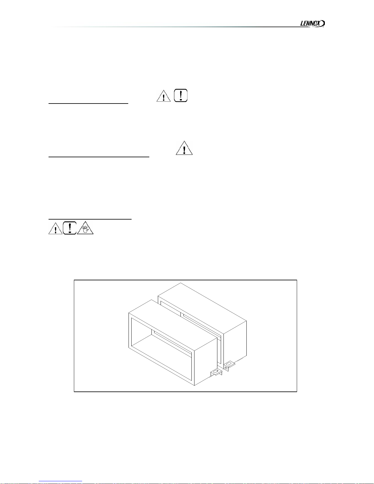
4.5 Connecting accessories
1. Fix the angular fixing clamp
2. Place together the fixing modules
3. Pass the M8 x 25 screw s through the adjacent holes and necessary washers (see diagram)
4. Screw the nut by hand
5. Tighten with an Allen key
Page 11
IOM / MINIAIR-0507 9
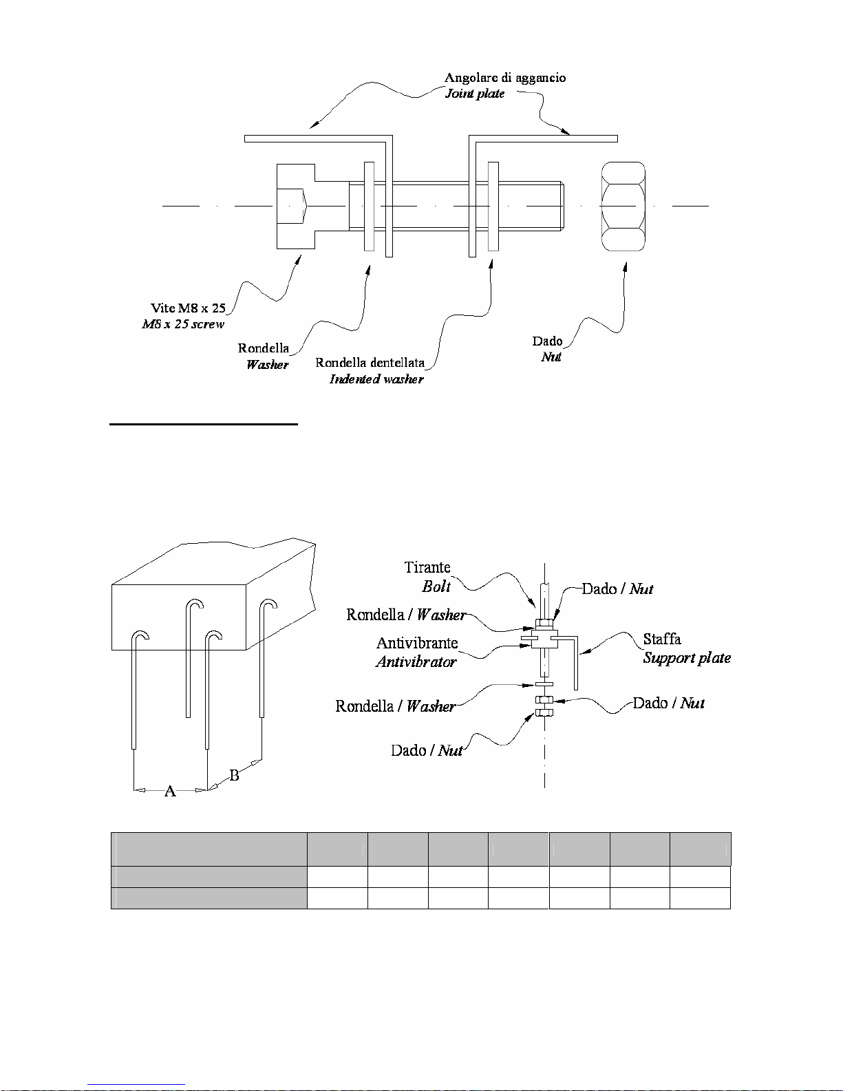
4.6 MINIAIR unit positioning
The unit is equipped with anti-vibration support plates.
As follows are indica tions the various sequence of assembly:
1. Carry out the drilling of the ceiling, and fit the four M8 threaded bolts as indicated in the diagram.
2. Position the unit on the four bolts using the supplied fixing plates.
3. Block the unit tightening the fixing bolts.
i. Dimensions
10 20 25 30 40 50 60
A
745 1105 1435 1435 1715 1820 2040
B
820 820 820 820 820 922 922
To aid the regular flow of the condensation, it is advised to install the unit with a 3mm inc lination towards the
condensation outlet.
Page 12
10 IOM / MINIAIR-0507
4.7 Duct connection
The Ducts must be the correct dimension based on the functions of syste m and the air diffusion characteristics
of the unit fans. A mistaken calculation of the ducting will cause power loss or the intervention of any eventual
devices present on the system.
To prevent the formation of condensation and cut down the sound level it is advised to use internally lined
Ducts.
To avoid the transmission of machine vibrations into the environment, it is advised to fit an anti-vibration joint
between the fans and Ducts. The electrical continuity must be guaranteed between the Ducts and the apparatus
via an earth cable.
4.8 Hydraulic connections
The installation and connecting of the piping is an operation that must be done correctly, otherwise it may
compromise the performance of the system. At worst it may cause irreversible damage to the machine. These
operations are to be effectuated by qualified personnel.
The MINIAIR units are supplied with “female” m oun ted, GAS threaded water coil s.
Extreme caution must be taken during the installation operation, to avoid damage.
The tube path must be studied in such a way to not create obstacles should an eventual extraction of unit coil or
filter be required.
Water inlet and outlet must occur allowing the thermal exchange in counterflow: follow the indications found on
the WATER INLET and WATER OUTLET plate.
Supply a lower valve for the emptying of the water contained in the coil.
Fix securely the tubes to the outside of the unit, so as to avoid offloading the weight onto the coil headers.
Once the connection has been followed, fix the external rubber seals against the panel to avoid passing of air.
The lining must just rest on the panel, to avoid the risk of burning.
Supply an interception valve to isolate the coil from the rest of the circuit in case of extraordinary maintenance.
Should the installation of the apparatus occur in areas with particula rly cold climates, empty the syste m prior to
an extended period of inutilization.
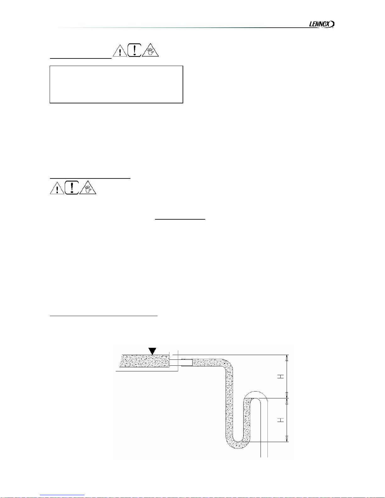
4.8.1 Condensation outlet connection
The stainless steel condensation drip tray is provided with 20 mm outlet diameter.
The system of drainage must provide an adequate trap.
The dimensions and execution of the trap must guarantee that H 50 mm.
IMPORTANT: IT IS IMPORTANT NOT TO PLACE
IN OPERATION THE UNIT IF THE FAN OUTLETS
ARE NOT DUCTED OR NOT PROTECTED BY A
SAFETY NET ADHERING WITH REGULATION
UNI 9219 OR SUCCESSIVE.
Page 13
IOM / MINIAIR-0507 11
The trap must have a tap for correct cleaning of the lower part, and must allow an easy disassembly.
The path of the condensation drainage tube must always have a gradient toward external.
Insure that the condensation run-off tube does not interfere with discharge of the unit.
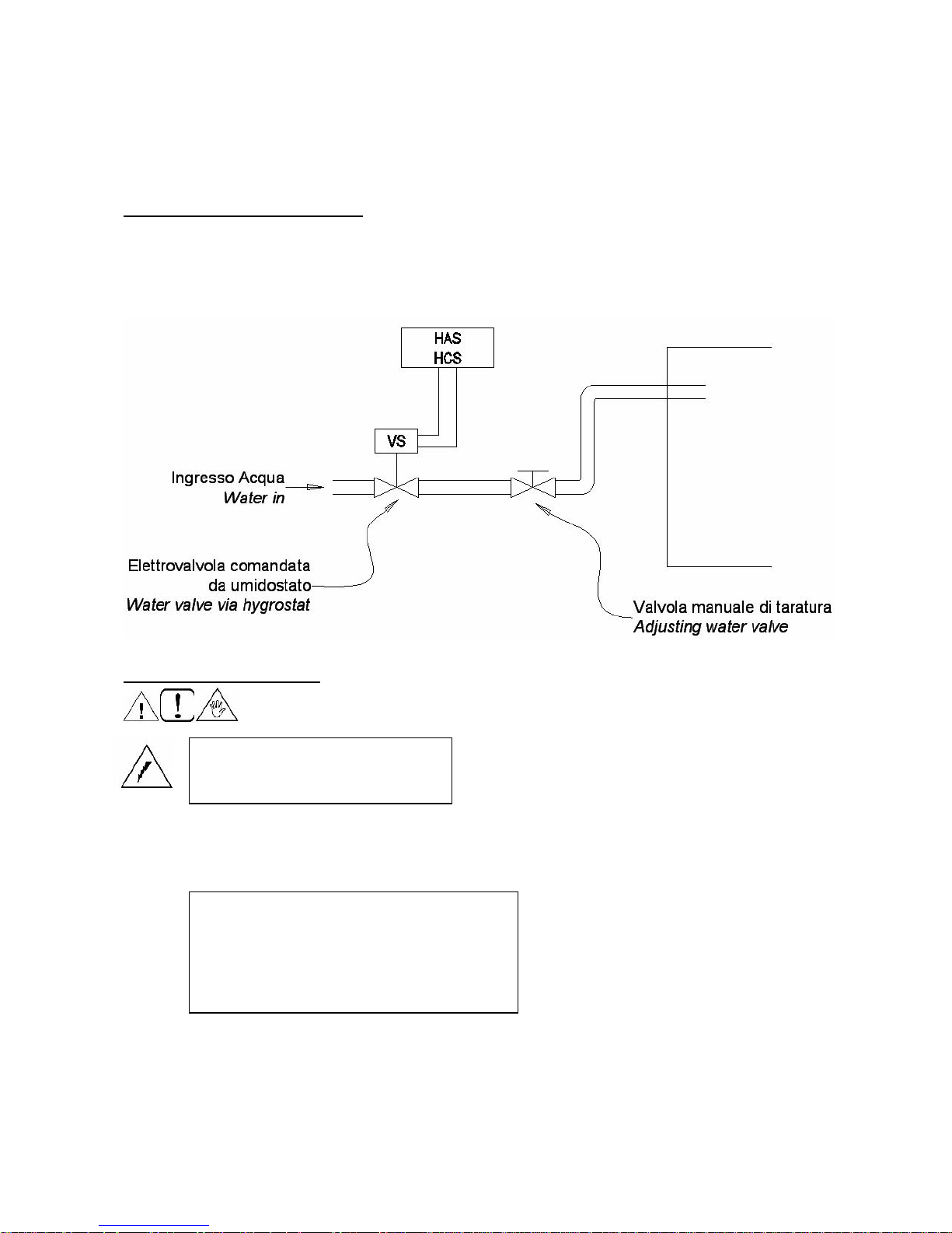
4.8.2 Water humidifier connection
The evaporative pack section is feeded by water public network (no water pump inside); the feeding system must provide
a valve (supplied by the installer) for the adjustment of the water flow; an excessive quantity may ove rflow the driptray
system present in the system.
For the drainage of the water and the realisation of the trap, see previous paragraph; furthermore it is recommended to
not reduce the diameter of the drainage tube till the sewer outlet, so as to avoid overflow and nasty odours.
4.9 Electrical connections
Qualified personnel according to the supplied schemes must carry out the electrical connections at the control
panel.
Insure that the voltage and the frequency shown on the technical plate correspond to the connecting power
supply.
For the general power supply of the unit and its accessories, the use of adapters, multiple plugs and extension
leads is to be avoided.
It is the responsibility of the installer to insure that the installation of the unit is as close as possible to
the mains power supply, or sufficiently close to protect the electrical parts.
Connect the unit to an efficient power point, using the correct screws as supplied with the unit.
Before starting any operation, insure
that the general power supply has
been switched off.
Connect the unit and its accessories using
adequate wiring for the used power while
respecting the country regulations. The
dimension of the wiring must be enough to
support a voltage drop in start up phase lower
than 3% of the nominal one.
Page 14

12 IOM / MINIAIR-0507
1 2
The electrical wiring diagrams of the ordered unit are supplied with it when delivered and they are related to the
real accessory selection.
SECTION 5 – PRE START CHECKLIST
5.1 Checks prior to Start-up
Before turning on the apparatus verify the following:
Fixing of unit to ceiling;
Connection of ducts;
Correct condensation run-off;
Connection of mains supply;
Closing of all electrical clamps.
SECTION 6 – STANDARD MAINTENANCE
It is the responsibility of the user to carry out all types of maintenance operations.
Only personnel previously trained and qualified may carry out maintenance operations.
Should the apparatus require disassembly, hand protection is required
6.1 Monthly maintenance
6.1.1 Filter section check
If the filter is dirty, open the lower panel door, remove the screws as seen in figure 1, remove filter door and remove the
filter from below (figure 2). For cleaning, utilise a vacuum cleaner or wash with normal detergent in warm water, dry well.
Remember to always fit the filter before re-starting the apparatus.
BEFORE FOLLOWING ANY TYPE OF
MAINTENANCE OPERATION, BE CERTAIN THAT
THE APPARATUS MAY NOT CASUALLY OR
ACCIDENTALLY BE CONNECTED TO THE
ELECTRICAL MAINS SUPPLY. THERFORE IT IS
NECESSARY TO SHUTDOWN THE UNIT’S
POWER SUPPLYAD PRIOR TO MAINTENANCE.
Page 15

IOM / MINIAIR-0507 13
6.1.2 Bag filter section check
The soft bag filters are high performance type and require periodical checking, as a marked deterioration may occur
during usage, especially at the point where they are attached to the main frame. This is due to the continuous
deformation, and for the weight of the dust caught.
These filters are not recyclable, and any cleaning may only be carried a few times by turning the filter upside down.
Should it become necessary to substitute the filters, verify the condition of the sealing, and proceed with the substitution.
The bags full of dust must be removed with great care, or to achieve a safer operation, cover the air inlet area. This will
avoid the over-spill of dust inside the apparatus.
6.1.3 Coil check
Check that the Coil exchanger is clean and in a perfect condition so as to guarantee correct performance.
6.1.4 Water humidifier section check
A periodical cleaning of the drip tray is recommended by using steam (high pressure or similar) or specific cleaning
products. Alternatively, replace the evaporation pack, efficient working of which is fundamental to guarantee the air
quality.
The pack must be replaced when limestone build-up is found.
The evaporative pack must be fitted in its correct position, controlling the air direction through the apparatus and the
water flow on the filter.
Always check the cleaning and the efficiency of the outlet and the inlet of the water section.
6.1.5 Power supply check
Control that the power supply voltage falls within the prescribed limits.
6.2 Yearly maintenance
Check that all the electrical equipment, in particular the fixing of the electrical connections.
Check the tightness of all nuts, bolts, flanges and hydraulic connections that the vibrations of the machine may have
loosened.
SECTION 7 – TROUBLESHOOTING
7.1 Finding faults
ANOMALY POSSIBLE CAUSE
The motor does
not run
Power supply not present
The thermostat switches are
not in their exact functioning
position
Material/foreign bodies
blocking moving parts
Loose electrical connections
Loss of
performance after
a period of
satisfactory
working
The filter and coil are dirty
The system is not correctly
balanced
Air present in hydraulic
system. Release with specific
valve.
Obstruction present in ducts
Page 16

14 IOM / MINIAIR-0507
SECTION 8 – SPARE PARTS
8.1 Spare part order
In the following table there are the codes of the unit components that might be replaced; the Customer must refer to
these codes for the possible spare part order. See 2.2 paragraph for the used quantity in the specific model.
Model
ii.
Sp
ar
e
pa
rt
10 20 25 30 40 50 60
Direct driven fan
03305021 AMF0000097 03305028 AMF0000040 AMF0000097 03305063 03305063
2-row water coil
03420192 03420193 03420105 03420105 03420106 03420199 03420202
4-row water coil
03420169 03420170 03420100 03420100 03420171 03420198 03420201
6-row water coil
03420194 03420195 03420102 03420102 03420196 03420150 03420200
G3 filter
AMF0002466
F6 bag filter
AMF0001743
SECTION 9 – MATERIAL DISPOSA L
9.1 Material disposal
At the end of the productive life cycle, the MINIAIR Unit must be dismantled and disposed of respecting the operational
regulations present in its country of installation.
The materials that the unit is constructed of are:
- Aluzink shee t metal;
- Zinc-plated sheet metal;
- Aluminium;
- Copper;
- Polye ster;
- Polye thylene ;
- Inox Stainless Steel;
- Plastic.
18.2
Page 17

IOM / MINIAIR-0507 15
MINIAIR+
SECTION 10 – PRESENTATION
10.1 Manual presentation
This instruction manual supplies the necessary information for the transportation, the installation, operation and
maintenance of the MINIAIR+ apparatus as supplied by the company LENNOX (from this point named as the supplier).
It supplies the user with as much information as is normally useful for a correct and secure installation of the unit.
Lack of observation of the details found within this manual, and an inadequate installation of the MINIAIR+ may cause
the withdrawal of the warranty supplied with the equipment.
Furthermore, the Supplier will not respond to any eventual damage, whether direct or indirect, caused by the incorrect
installation, or for damages caused by the installation being effectuated by inexperienced or unauthorised personnel.
Verify, upon acquisition, that the apparatus is complete and supplied as described.
Any eventual disputes must be presented in writing within 8 days from the reception of the goods.
10.2 Machine identification
The MINIAIR+ Unit is provided with identification plate listing the following:
- Address of Constructor
- “CE” Mark
- Model
- Serial Number
- Maximum Current absorbed in “A”
- Power supply voltage in “V”
- Power supply frequency in “Hz”
- Number of phases indicated with “Ph”
- Date of fabrication
- Gross weight in “Kg”
SECTION 11 – TECHNICAL CHARACTERISTICS
11.1 General characteristics
Completely removable aluzink plate side panels.
Panel thermal and acoustic insulation by means of polyethylene/polyester panels with a medium thickness of 20
mm.
High efficiency aluminium plate static type heat recuperators, with air flows separated by special seals.
UE3 efficiency air filters, which may be easily removed from the sides allowing their periodic cleaning.
Fan bodies mounted on anti-vibrators.
Double inlet centrifugal fans (for MINIAIR+03 single inlet fans) which may be removed from the sides for
periodic maintenance.
Multi-speed directly coupled electric motors..
To aid the electrical connections and ventilator control, a terminal block with a relay board is fitted.
Stainless steel condensation colle cting tray, with condensation drainage towards the lower part
11.2 Accessories
Electrica l reheating SKE
Water coil for reheating SKW
Regulation damper SKR
Speed selector CVU
Apparatus Control Panel PCU
Pressure operated soiled filter cut-off switch PSTD
Servomotor for damper regulations SSE
Anti-free ze thermostat TE G
Page 18

16 IOM / MINIAIR-0507
11.3 Packing dimensions
Model 03 06 10 14 19 25 30 40
A (mm) 990 990 1150 1350 1450 1700 1700 1700
B (mm) 750 750 860 900 900 1230 1230 1230
C (mm) 270 270 385 410 470 490 530 630
L (mm) 127 164 240 240 240 306 339 339
H (mm) 112 100 218 270 270 270 297 297
L1 (mm) 275 275 330 337 337 502 502 502
H1 (mm) 153 153 267 267 327 347 387 487
D (mm) - - 230 230 280 305 305 405
E (mm) 120 197 225 241 230 323 308 308
F (mm) 135 171 238 224 284 304 331 431
G (mm) 195 195 222 239 239 321 321 321
- - G ¾ G ¾ G ¾ G ¾ G ¾ G ¾
Page 19

IOM / MINIAIR-0507 17
11.4 Unit technical data
Model
MINIAIR+
03
MINIAIR+
06
MINIAIR+
10
MINIAIR+
14
MINIAIR+
19
MINIAIR+
25
MINIAIR+
30
MINIAIR+
40
Air flow m3/h 290 550 1000 1400 1900 2500 3200 4000
Available static pressure Pa 60 65 90 140 120 110 170 170
Liv. Sound pressure dB (A)
53 54 54 59.5 58 57,5 60,5 62
Fans
MINIAIR+
03
MINIAIR+
06
MINIAIR+
10
MINIAIR+
14
MINIAIR+
19
MINIAIR+
25
MINIAIR+
30
Section 1.02
INIAIR+
40
Absorbed power W 2 x 45 2 x 65 2x 147 2x 350 2x 350 2x 350 2x 550 2x 750
Poles n° 4 2 4 4 4 4 4 4
Max current A 1,32 1,6 3 5,8 6,2 6 11,4 6,2
N° fan speed 2 2 3 3 3 3 3 2
Protection 20 44 44 55 44 55 20 55
Insulation Class B F F F F F F F
Power supply
V/ph/Hz
230 / 1 / 50 400/3/50
Thermal recuperator (*)
MINIAIR+
03
MINIAIR+
06
MINIAIR+
10
MINIAIR+
14
MINIAIR+
19
MINIAIR+
25
MINIAIR+
30
MINIAIR+
40
Efficiency % 52,3 54,6 53,4 52,1 51,8 57,6 56 55,6
Capaicty recovered kW 1,34 2,57 4,6 6,2 8,4 12,3 15,3 19,4
Outlet temp °C 8,1 8,7 8,3 8,0 7,9 9,4 9,0 8,9
Filters(*)
MINIAIR+
03
MINIAIR+
06
MINIAIR+
10
MINIAIR+
14
MINIAIR+
19
MINIAIR+
25
MINIAIR+
30
MINIAIR+
40
Efficiency G3 G3 G3 G3 G3 G3 G3 G3
Frontal air speed m/s 1,7 3,6 2,9 4,1 4,5 3,8 4,3 4,3
Size mm
300
178
48
300
178
48
356
293
48
356
293
48
363
353
48
528
373
48
528
413
48
628
413
48
(*) Size valued in the following hypothesis: Ting. External =-5°C; T ambient 20°C ; nominal air flow.
Page 20

18 IOM / MINIAIR-0507
11.5 Accessories technical data
11.5.1 Water coil for reheating
Section 1.03 Coil code SKW 10 SKW 14 SKW 19 SKW 25 SKW 30 SKW 40
Geometry 25 22 25 22 25 22 25 22 25 22 25 22
Tubes per row N ° 14 14 16 17 17 21
Rows N ° 3 3 3 3 3 3
Fin pitch mm 2.5 2.5 2.5 2.5 2.5 2.5
Capacity KW 9.4 13.4 16.6 23.9 28.4 36.2
Outlet temp ° C 36 36.6 34.1 36.6 34.5 34.3
Air pressure drop Pa 65 64 85 62 85 92
Water pressure drop kPa 8 16 10 11 15 27
Size valued in the fol lowing hypothesis:
Water 70/60°C;
Air entrance temperature 8°C;
Nominal air volume.
11.5.2 Electrical reheating
Coil code SKE 03 SKE 06 SKE 10 SKE 14 SKE 19 SKE 25 SKE 30 SKE 40
Electrical coil 1 stage kW 2 4 4.5 6 9 12 12 12
Power supply V 230 230 400 400 400 400 400 400
Phases n° 1 1 3 3 3 3 3 3
Stage n° 1 1 1 1 1 1 1 1
Absorbed current A 8.7 17.4 6.5 8.7 13 17.3 17.3 17.3
Outlet Air Temp (+) °C 28.4 27.8 21.3 20.7 22 22.2 19.5 17
(+) Size valued with Ting air = 8°C and nominal air capacity.
Page 21

IOM / MINIAIR-0507 19
11.6 Possible positioning
For each size available, four possible positions for the recuperators are available. Depe nding on the ne t configuration,
and available space, one of the four possibilities below may be employed
11.6.1 Horizontal unit orientation
11.6.2 Vertical unit orientation
ESTERNO
OUTSIDE
INTERNO
Mandata
aria preriscaldata
INSIDE
Ripresa
aria ambiente
Tipo "A" - Type "A"
ESTERNO
OUTSIDE
Tipo "B" - Type "B"
INTERNO
INSIDE
Espulsione
aria viziata
Air b low-out
Aspira zione
aria di rinnovo
Air in take
renewal
ESTERNO
Aspirazione aria di rinnovo
OUTSIDE
Tipo "C" - Type "C"
INTERNO
Mandata aria preriscaldata
Ripresa aria ambiente
INSIDE
Espulsione aria viziata
INSIDE
INTERNO
ESTERNO
OUTSIDE
Tipo "D" - Type "D"
A90 R90
E90 M90
E90 M90
A90 R90
R90M90
E90 A90
E90
M90
A90
R90
Internal air
iduction
Imput pr e
heated air
Air in take
renewal
Air blow-out
Espulsione
aria viziata
Aspira zione
aria di rinnovo
Internal air
iduction
Mandata
aria preriscaldata
Imput pr e
heated air
Ripresa
aria ambiente
Imput pre heated air
Internal air duction
Air blow-out Air intake renewal
Espulsione aria viziata
Air blow-out Air intake renewal
Aspirazione aria di rinnovo
Internal air duction
Ripresa aria ambiente
Imput pre heated air
Mandata aria preriscaldata
Tipo "C" - Ty pe "C "
Tipo "D" - Type "D"
Tipo "B" - Type "B"
Tipo "A" - T ype "A "
E90
A90
M90
R90
Espulsione
aria viziata
Air blow-out
Mandata
aria preriscaldata
Imput pre
heated air
Aspirazione
aria di rinnovo
Air intake
renew al
Ripresa
aria ambiente
Internal air
iduc tion
Espulsione
aria viziata
Air blow-ou t
A90
Air intake
renewal
Aspirazione
aria di rinnovo
E90
R90
Imp ut pre
heated air
Mandata
aria preriscaldata
M90
Inte r nal air
iduction
Ripresa
aria ambiente
Espulsione
aria viziata
Air blow-out
E90
Air intake
renewal
Aspirazione
aria di rinnovo
M90
A90
Imput pre
heated air
Mandata
aria preriscaldata
R90
Internal air
iduc tion
Ripresa
aria ambiente
Mandata
aria preriscaldata
M90
Air blow-ou t
Espulsione
aria viziata
Impu t pre
heated air
E90
Ripresa
aria ambiente
R90
Aspirazione
aria di rinnovo
Air intake
renew al
Inte r nal air
iduction
A90
Page 22

20 IOM / MINIAIR-0507
Aspirazione aria di rinnovo
Tipo "A" - Type "A"
Espulsione aria viziata
R90M90
Air blow-out
Air intake renewal
Internal air duction
Ripresa aria ambiente
Imput pre heated air
Mandata aria preriscaldata
M90
Tipo "B" - Type "B"
Air intake
renewal
Aspirazione
aria di rinnovo
Espulsione
aria viziata
Air blow-out
E90
Imput pre
heated air
Ripresa
aria ambiente
Internal air
iduction
Mandata
aria preriscaldata
61,5681
61,5681
11.6.3 Vertical unit with post-heating coil
As shown in the figu re below, by simply changing the position of two panels it is possible to suck or blow out air from the
sides instead from the front of the unit
Page 23

IOM / MINIAIR-0507 21
11.7 By-pass for de-frosting or free-cooling
For MINIAIR+ 03-06-10-14-19-25-30 models the structure has a presplitting allowing defrosting by-pass or free cooling to
be carried out.
Free cooling. When the external tem perature is close to the internal temperature the recuperator may be bypassed
inserting renewal air directly in the room.
It is possible to do this by opening damper B and at the same time closing damper A.
Defrosting. In very cold periods the room delivery air could frost blocking the passage through the recuperator. Installing
an antifreeze thermostat (optional) combined with the bypass system indicated in the figure unit defrosting is obtained. In
fact opening gate A and closing gate B the recuperator is bypassed with cold air and the flow of hot air coming from the
room air delivery allows a rapid defrosting of the recuperator itself which can therefore return to operation in normal
conditions.
SECTION 12 – TRANSPORTATION
12.1 Packing
The recuperators are placed in carton boxes that must remain intact until the moment of installation.
The materials that are not required for technical motives are supplied in fitted packing fixe d externally and internally to
the unit.
ESTERNO
OUTSIDE
Espulsione
aria viziata
Air blow-out
Aspirazione
aria di rinnovo
Air intake
renewal
Imput pre
heated air
Mandata
aria preriscaldata
INTERNO
Internal air
iduction
Ripresa
aria ambiente
INSIDE
Serranda A
Serranda B
Schema 1
Air free cooling
Aspirazione
aria free cooling
INTERNO
INSIDE
Ripresa
aria ambiente
Mandata
aria preriscaldata
Internal air
iduction
Air intake
renewal
Espulsione
aria viziata
Air blow-out
ESTERNO
Aspirazione
aria di rinnovo
OUTSIDE
Imput pre
heated air
Schema 2
Serranda C
Serranda E
Serranda D
Page 24

22 IOM / MINIAIR-0507
12.2 Transportation
For the lifting and transportation of the unit, use adequate equipment, according to the 89/391/CEE regulations and
successive modifications.
Each individual machine weight is listed in this manual.
Avoid rotation without control.
12.3 Checklist
Upon reception of the apparatus, we suggest that a complete control is carried out, to verify that the unit is intact and
complete, and no damage has been sustained during transport. Any eventual damage revealed must be communicated
to the carrier, demonstrating the reserve clause within the transport documents, specifying the type of damage.
12.4 Storing
In case of long term storage, the apparatus must be kept free from dust, and away from areas susceptible to heat and
vibration.
The manufacturer declines any responsibility for any damage as a result of negligence or lack of protection from
atmospheric agents.
SECTION 13 – INSTALLATION & CONNECTION
13.1 Definition
CLIENT– The client is the person, activity or the society, that has bought or hired the apparatus, and intends to utilise the
machinery for its intended use.
USER / OPERATOR – The User or Operator, is the actual person that has been authorised by the client to utilise the
apparatus.
TECHNICIAN – Defined as the person who has followed a relevant/specific course of study, and so is able to understand
the dangers derived from the use of the apparatus, and in turn, due to this, are capable of solving major dilemmas.
13.2 Safety regulations
Qualified personnel must carry out the installation.
During the installation operation, use protective clothing, for e xample: glasses, gloves, etc. as indicated by
686/89/CEE and successive regula tions.
During the installation operate in absolute security, pollution free air and in an area free of obstructions.
Respect the regulations in force in the country in which the apparatus is being installed. Specifically relative to
its use, and to the disposal of packing and products used for the cleaning and maintenance of the unit. Respect
the recommendations given by the producers of such products.
Before placing in function the unit, check the perfect connection of the various components and the internal
parts of the system.
Avoid at a ll costs human contact with moving parts and contact w ith the parts themselves.
Do not commence with servicing or cleaning of the unit, before the unit has been disconnected from the
main supply.
The Manufacturer declines any responsibility for
failure to respect the Safety Regulations, and the
prevention as described below.
Furthermore, the manufacturer declines any
responsibility for damage caused by the improper
use of the unit and/or modifications carried out
without proper authorisation.
Page 25

IOM / MINIAIR-0507 23
The maintenance and the substitution of damaged or consumed parts must be carried out on ly by specia lise d
personnel, following the indications found within this manual.
Spare parts must correspond to the requirements specified by Manufacturer .
In case of dismantling of the unit, respect the anti-pollution regulations in force.
N.B. The installer and the user of the apparatus must take into account, and solve problems, connected with any other
type of risk that may occur to the unit. For example, risks derived from the entrance of foreign bodies, or risks due to the
presence of flammable or toxic gas.
13.3 Preliminary operations
Check the perfect condition of the various components of the unit.
Control that contained within the packing, there are the installation accessories, and documentation.
Transport the packed section as close as is possible to the intended place of installation.
Do not place tools or weight on top of the packed unit.
13.4 Choosing place of installation
Positio n the unit on a solid structure, that will not vibrate, and is capable supporting the weight of the machine.
Positio n the unit in a point where the condensation discharge may occur easily.
Do not position the unit in an area in which flammable gases, acidic or corrosive substances are present. They
may damage various components in an irreparable manner.
Allow a min imum amount of free space as indicated in the figure. This permits ease of installation and
maintenance.
Min 500
Page 26

24 IOM / MINIAIR-0507
Model 03 06 10 14 19 25 30
Section 1.04 A 300 300 350 400 400 450 450
13.5 Machine positioning
Min 500
A
Page 27

IOM / MINIAIR-0507 25
Model 03 06 10 14 19 25 30
Section 1.05 A 796 796 906 946 946 1276 1276
B 940 940 1100 1230 1380 1630 1630
C 700 700 810 830 830 1160 1160
D 1036 1036 1196 1346 1496 1746 1746
To aid the regular flow of the condensation, it is advised to install the apparatus with a 3 mm inclination towards the
condensation outlet.
13.6 Duct connection
The Ducts must be the correct dimension based on the functions of system and the air diffusion characteristics
of the unit fans. A mistaken calculation of the ducting will cause power loss or the intervention of any eventual
devices present on the system.
To prevent the formation of condensation and cut down the sound level it is advised to use internally lined
Ducts.
To avoid the transmission of machine vibrations into the environment, it is advised to fit an anti-vibration joint
between the fans and Ducts. The electrical continuity must be guaranteed between the Ducts and the apparatus
via an earth cable.
IMPORTANT: IT IS IMPORTANT N OT TO PLACE
IN OPERATION THE UNIT MINIAIR+ IF THE
MOUTHS OF THE FANS ARE NOT DUCTED OR
NOT PROTECTED BY A SAFETY NET
ADHERING WITH REGULATION UNI 9219 OR
SUCCESSIVE.
Page 28

26 IOM / MINIAIR-0507
13.7 Hydraulic connections
The installation and connecting of the piping is an operation that must be done correctly , otherwise it may compromise
the performance of the system. At worst it may cause irreversible damage to the machine. These operations are to be
effectuated by qualified personnel.
13.7.1 Condensation outlet connection
The condensation drip tray in stainless steel inox has a depth of D. 12 mm.
The system of drainage must provide an adequate trap to prevent the undesirable entrance of air into the
system in depression. The trap is also useful to avoid the infiltration of odours and insects.
The dimensions and execution of the trap must guarantee that H P, where P is expressed in mm.c.a, and is
equal to the useful static pressure of the unit installed.
The trap must have a tap for correct cleaning of the lower part, and must allow an easy disassembly.
The path of the condensation drainage tube must always have a gradient toward external.
Insure that the condensation run-off tube does not interfere with discharge of the unit.
13.7.2 Eventual connection for SKW water reheating coil
The eventual water reheating coil is supplied with “male” connections with gas threads.
The tightening must be carried out with extreme care to avoid damage to the copper collectors of the coil.
The path of the tubes must be studied in a way to avoid obstacles should it be necessary to extract the unit coil.
Inlet and outlet water must consent the thermal exchange against the current. Follow instructions found on the
WATER INLET and WATER OUTLET plate.
Provide an escape valve at the top of the unit, and a discharge valve a t the bottom.
Reinforce sufficiently the units external tubes to avoid offloading the weight onto the coil.
Once connection has been effectuated, fix the external seal flush against the control panel, in this way avoiding
the passing of air.
La insulation must not rest against the panelling, as this may provoke burning.
For control purposes, organize the interception of the tube side coil when the fan is off, to avoid internal
overheating and possible damage to internal components.
Provide an anti-freeze system.
Provide a cut out switch to isolate the coil from the rest of the circuit in case of extensive maintenance needs.
Should the unit be installed in particularly cold areas, drain completely before long periods of in-operation.
Page 29

IOM / MINIAIR-0507 27
13.8 Electrical connections
Qualified personnel according to the supplied schemes must carry out the electrical connections at the control
panel.
Insure that the voltage and the frequency shown on the technical plate correspond to the connecting power
supply.
For the general power supply of the unit, and its accessories, the use of adapters, multiple plugs and extension
leads is to be avoided.
It is the responsibility of the installer to insure that the installation of the unit is as close as possible to
the mains power supply, or sufficiently close to protect the electrical parts.
Connect the unit to an efficient power point, using the correct screws as supplied with the unit.
In the unit with rel ay board the screws of the connectors must be screwed with tork equal to 0,5 Nm
13.9 Installation of CVU & PCU accessories
13.9.1 CVU speed control
Adaptable for wall installation, allows the possibility to select one of three fan speeds.
Present on the control panel is:
- On – Off switch;
- Three speed Selector switch.
Installation and fitting
1. Loosen the central screws;
2. Remove the cap;
3. Fix the base to the wall, approximately 1,5 metres from the floor surface;
4. Carry out electrical connections;
5. Replace cap, and tighten central screws.
Before commenci
ng any operation,
insure that the general power supply
has been isolated
Follow the connection of the unit and its
accessories using adequate cabling for the
power used, and respecting the country
regulations. The dimensions of the cabling must
be sufficient to support a voltage drop in start
up phase inferior to 3% of the nominal
Page 30

28 IOM / MINIAIR-0507
Technical characteristics
Power supply: 230 +/- 10% Vac ; 50/60Hz
Control:
Manual : On / Off
Manual : Min/ Med / Max
Relay capacity: 6A with resistive load
13.9.2 PCU Control panel
Adaptable for wall installation, the PCU Control Panel allows environmental temperature control, for both summer and
winter. It also allows the possibility to select the three speed Electro-fan.
Present on the control panel is:
- On (summer -winter ) – Off switch;
- Switch for temperature regulation;
- Three speed Selector switch;
Technical characteristics
Power supply: 230 +/- 10% Vac ; 50/60Hz
Control:
Manual : On / Off
Manual : Min/ Med / Max
Relay capacity: 6A with resistive load
Page 31

IOM / MINIAIR-0507 29
SECTION 14 – ELECTRICAL SCHEMES
14.1 MINIAIR+ 03-06 direct connection
14.2 MINIAIR+ 03-06 connection with CVU speed control
MM
NELLO SCHEMA E' INDICATO IL FUNZIONAMENTO ALLA MINIMA VELOCITA'.
IL FUNZIONAMENTO ALL' ALTA VELOCITA' COLLEGARE IL NEUTRO CON IL MORSETTO 2.
POSSIBLE EXTERNAL AGREMEENT
THE DIAGRAM SHOWS OPERATION AT THE LOW SPEED.
FOR THE HIGH SPEED CONNECT THE NEUTRAL WITH CLAMP n°2.
THE CONNECTION TO BE CARRIED OUT BY THE INSTALLER ARE SHOWN BY THE DOTTER LINE.
ALL THE CONNECTIONS MUST BE PROTECTED ST THE SOURCE BY THE INSTALLER.
ALTA VELOCITA' / HIGH SPEED
BASSA VELOCITA' / LOW SPEED
COMUNE / COMMON
EVENTUALE CONSENSO ESTERNO
I COLLEGAMENTI A CURA DELL'INSTALLATORE SONO INDICATI A TRATTEGGIO.
TUTTE LE LINEE DEVONO ESSERE PROTETTE ALL'ORIGINE A CURA DELL'INSTALLATORE
NF
N
F13
RELE'
2
RELE'
V1
V2
V3
1
RELE'
N
F
BASSA VELOCITA' / LOW SPEED
ALTA VELOCITA' / HIGH SPEED
I COLLEGAMENTI A CURA D ELL'INSTAL LATORE SONO INDICATI A TRATTEGGIO.
TUTTE LE LINE E DEVON O ESSERE PROTETTE ALL'O RIGINE A CURA DEL L ' INSTALLATORE
THE CONNECTION TO BE CARRIED OUT BY THE INSTALLER ARE SHOWN BY THE DOTTER LINE.
ALL THE CONNECTIONS MUST BE PROTECTED ST THE SOURCE BY THE INSTALLER.
V2
V1
COMUNE / COMMON
V3
N
6
CVU
RELE'
1 2
1 2
3 4 5
N
F
RELE'
RELE'
F13 NF
M M
Page 32

30 IOM / MINIAIR-0507
14.3 MINIAIR+ 03-06 connection with SKE & PCU control panel
14.4 MINIAIR+ 10-14-19-25 direct connection
QUADRO COMANDO SKE SINGOLA / DOPPIA RESISTENZA
THE CONNECTION TO BE CARRIED OUT BY THE INSTALLER ARE SHOWN BY THE DOTTER LINE.
ALL THE CONNECTIONS MUST BE PROTECTED AT THE SOURCE BY THE INSTALLER.
I COLLEGAMENTI A CURA DELL'INSTALLATORE SONO INDICATI A TRATTEGGIO.
TUTTE LE LINEE DEVONO ESSERE PROTETTE ALL'ORIGINE A CURA DELL'INSTALLATOR E
SOLO CON RKE06
TSTS
SKE CONTROL CABINET
S1
N
R2
S2 R1
N
F
F
CONTROL PANEL FAN
QUADRO COMANDO VENTILATORI
ALTA VELOCITA' / HIGH SPEED
BASSA VELOCITA' / LOW SPEED
COMUNE / COMMON
3
2
M M
RELE'
1
V3
V2
V1
RELE'2RELE'
3 F1NF N
2 31 139 10 11 126 7 84 5
PCU
MM
NELLO SCHEMA E' INDICATO IL FUNZIONAMENTO ALLA MINIMA VELOCITA'.
IL FUNZIONAMENTO ALLA MEDIA VELOCITA' COLLEGARE IL NEUTRO CON IL MORSETTO 2.
IL FUNZIONAMENTO ALL'ALTA VELOCITA' COLLEGARE IL NEUTRO CON IL MORSETTO 3.
POSSIBLE EXTERNAL AGREMEENT
THE DIAGRAM SHOWS OPERATION AT THE LOW SPEED.
FOR THE MEDIUM SPEED CONNECT THE NEUTRAL WITH CLAMP n°2.
FOR THE HIGH SPEED CONNECT THE NEUTRAL WITH CLAMP n°3.
THE CONNECTION TO BE CARRIED OUT BY THE INSTALLER ARE SHOWN BY THE DOTTER LINE.
ALL THE CONNECTIONS MUST BE PROTECTED ST THE SOURCE BY THE INSTALLER.
ALTA VELOCITA' / HIGH SPEED
MEDIA VELOCITA' / MEDIUM SPEED
BASSA VELOCITA' / LOW SPEED
COMUNE / COMMON
EVENTUALE CONSENSO ESTERNO
I COLLEGAMENTI A CURA DELL'INSTALLATORE SONO INDICATI A TRATTEGGIO.
TUTTE LE LINEE DEVONO ESSERE PROTETTE ALL'ORIGINE A CURA DELL'INSTALLATORE
NF
N
F13
RELE'
2
RELE'
V1
V2
V3
1
RELE'
N
F
Page 33

IOM / MINIAIR-0507 31
14.5 MINIAIR+ 10-14-19-25 connection with CVU speed control
14.6 MINIAIR+ 10-14-19-25 connection with SKE & PCU control panel
QUADRO COMANDO SKE SINGOLA / DOPPIA RESISTENZA
THE CONNECTION TO BE CARRIED OUT BY THE INSTALLER ARE SHOWN BY THE DOTTER LINE.
ALL THE CONNECTIONS MUST BE PROTECTED AT THE SOURCE BY THE INSTALLER.
KMR2
I COLLEGAMENTI A CURA DELL'INSTALLATORE SONO INDICATI A TRATTEGGIO.
TUTTE LE LINEE DEVONO ESSERE PROTETTE ALL'ORIGINE A CURA DELL'INSTALLATORE
SKE CONTROL CABINET
TS TS
KMR1
T1
S T
S2R2 T2R1
S
N
R
T
R
S1
CONTROL PANEL FAN
QUADRO COMANDO VENTILATORI
ALTA VELOCITA' / HIGH SPEED
MEDIA VELOCITA' / MEDIUM SPEED
COMUNE / COMMON
3
2
M M
RELE'
1
V3
V2
V1
RELE'2RELE'
3 F1NF N
TS TS
1 2
PCU
643 5 7 8 9 10 11 12 13
BASSA VELOCITA' / LOW SPEED
THE CONNECTION TO BE CARRIED OUT BY THE INSTALLER ARE SHOWN BY THE DOTTER LINE.
ALL THE CONNECTIONS MUST BE PROTECTED ST THE SOURCE BY THE INSTALLER.
V3
I COLLEGAMENTI A CURA DELL'INSTALLATORE SONO INDICATI A TRATTEGGIO.
TUTTE LE LINEE DEVONO ESSERE PROTETTE ALL'ORIGINE A CURA DELL'INSTALLATORE
RELE'
RELE'
RELE'
V1
V2
CVU
1
1 2 3 F1
32 4 5 6
F
N
M M
BASSA VELOCITA' / LOW SPEED
ALTA VELOCITA' / HIGH SPEED
MEDIA VELOCITA' / MEDIUM SPEED
COMUNE / COMMON
N
F N
Page 34

32 IOM / MINIAIR-0507
14.7 MINIAIR+ 30 direct connection
14.8 MINIAIR+ 30 connection with CVU speed control
THE CONNECTION TO BE CARRIED OUT BY THE INSTALLER ARE SHOWN BY THE DOTTER LINE.
ALL THE CONNECTIONS MUST BE PROTECTED ST THE SOURCE BY THE INSTALLER.
F1
I COLLEGAMENTI A CURA DELL'INSTALLATORE SONO INDICATI A TRATTEGGIO.
TUTTE LE LINEE DEVONO ESSERE PROTETTE ALL'ORIGINE A CURA DELL'INSTALLATORE
1
RELE'
V2
EVENTUALE CONSENSO ESTERNO
POSSIBLE EXTERNAL AGREMEENT
N
F
RELE'
V1
1 2
M
RELE'
N
V3
3 F1 F N
RELE'
RELE'
V2
V1
1 2 3
F12 3 F N
M
RELE'
V3
N
F N
THE CONNECTION TO BE CARRIED OUT BY THE INSTALLER ARE SHOWN BY THE DOTTER LINE.
ALL THE CONNECTIONS MUST BE PROTECTED ST THE SOURCE BY THE INSTALLER.
I COLLEGAMENTI A CURA DELL'INSTALLATORE SONO INDICATI A TRATTEGGIO.
TUTTE LE LINEE DEVONO ESSERE PROTETTE ALL'ORIGINE A CURA DELL'INSTALLATORE
CVU
F
N
1 2 3
1
COMUNE / COMMON
BASSA VELOCITA' / LOW SPEED
MEDIA VELOCITA' / MEDIUM SPEED
F
V1
RELE'
V2
V3
RELE'
RELE'
21 F13
N
N
M
54 6
F12 3 F N
MEDIA VELOCITA' / MEDIUM SPEED
COMUNE / COMMON
V1
V2
RELE'
RELE'
V3
N
RELE'
21 3 F1 F N
M
ALTA VELOCITA' / HIGH SPEED
ALTA VELOCITA' / HIGH SPEED
BASSA VELOCITA' / LOW SPEED
Page 35

IOM / MINIAIR-0507 33
14.9 MINIAIR+ 30 connection with SKE & PCU control panel
14.10 MINIAIR+ 40 direct connection
SKE CONTROL CABINET
QUADRO COMAN DO S K E
SINGOLA / DOPPIA RESISTENZA
THE CONNECTION TO BE CARRIED OUT BY THE INSTALLER ARE SHOWN BY THE DOTTER LINE.
ALL THE CONNECTIONS MUST BE PROTECTED AT THE SOURCE BY THE INSTALLER.
T2
I COLLEGAMENTI A CURA DELL'INSTALLATORE S ONO INDICATI A TRATTEGGIO.
TUTTE LE LINEE DEVONO ESSERE PROTETTE ALL'ORIGINE A CURA DELL'INSTALLATORE
TRN
S
KMR1
S1R1 T1 S2R2
T
S
R
TS
MEDIA VELOCITA' / MEDIUM SPEED
BASSA VELOCITA' / LOW SPEED
MEDIA VELOCITA' / MEDIUM SPEED
RELE'
RELE'
RELE'
RELE'
RELE'
RELE'
CONTROL PANEL FAN
QUADRO COMAN DO VE N T ILAT OR I
COMUNE / COMMON
ALTA VELOCITA' / HIGH SPEED
V2
KMR2
V1 V3
N
COMUNE / COMMON
V3
V2V1N
TS
21
32
1
M
3 F1 F N
FF132 N
M
1 2 3 F1 F N
TS
TS
51 32 4
PCU
6 7 8 9 10 11 12 13
ALTA VELOCITA' / HIGH SPEED
BASSA VELOCITA' / LOW SPEED
Page 36

34 IOM / MINIAIR-0507
14.11 MINIAIR+ 40 connection with CVU speed control
14.12 MINIAIR+ 30 connection with SKE & PCU control panel
Page 37

IOM / MINIAIR-0507 35
SECTION 15 – PRE-START CHECKLIST
6.1 Checks prior to initial start-up
Before turning on the apparatus verify the following:
1. Fixing of unit to ceiling;
2. Connection of ducts;
3. Correct condensation run-off;
4. Connection of mains supply;
5. Closing of all electrical clamps.
SECTION 16 – STANDARD MAINTENANCE
It is the responsibility of the user to carry out all types of maintenance operations.
Only personnel previously trained and qualified may carry out maintenance operations.
Should the apparatus require disas sembly, hand protection is required
16.1 Monthly maintenance
16.1.1 Filter section checklist
Possibility for inspection to replace filters from below 1 and laterally 2
BEFORE FOLLOWING ANY TYPE OF
MAINTENANCE OPERATION, BE CERTAIN THAT
THE APPARATUS MAY NOT CASUALLY OR
ACCIDENTALLY BE CONNECTED TO THE
ELECTRICAL MAINS SUPPLY. THERFORE IT IS
NECESSARY TO SHUTDOWN THE UNIT’S
POWER SUPPLYAD PRIOR TO MAINTENANCE.
Page 38

36 IOM / MINIAIR-0507
To remove filter, dis-assemble the guides and extract filter.
For the cleaning, utilize a vacuum cleaner or wash with normal detergent and warm water, allow to dry well. Remember
to assemble the filter before operating the unit.
16.1.2 Recuperator Checklist
Verify that the plate e xchanger does not demonstrate signs of impurity, as this may lower significantly its efficiency. It is
possible to dismantle the recuperator from below, removing the condensation drip tray.
Unscrew the plugs 1, remove the tray and extract the recuperator pack
16.1.3 Condensation discharge Checklist
Remove side panel and clean, if necessary, the dirt and impurities that have formed in the condensation tray. Also check
the efficiency of the siphon.
16.1.4 Water coil Checklist
Check that the coil exchanger (optional ) is clean and in perfect state to guarantee the normal levels of performance.
16.2 Yearly maintenance
Check that all the electrical equipment, in particular the fixing of the electrical connections.
Check the tightness of all nut, bolts, flanges and hydraulic connections that the vibrations of the machine may have
loosened.
Page 39

IOM / MINIAIR-0507 37
SECTION 17 – TROUBLESHOOTING
17.1 Finding Faults
SYMPTOMS REASON
The motor does
not turn
Power supply not present
The thermostat switches are
not in their exact functioning
position
Material/foreign bodies
blocking moving parts
Loose electrical connections
Loss of
performance after
a period of
satisfactory
running
The filter and plate
exchanger are dirty
Obstruction present in ducts
SECTION 18 – MATERIAL DISPOSAL
18.1 Material Disposal
At the end of the productive life cycle, the MINIAIR+ Unit must be dismantled and disposed of respecting the operational
regulations present in its country of installation.
The materials that the unit is constructed of are:
- Aluzink shee t metal;
- Zinc-plated sheet metal;
- Aluminium;
- Copper;
- Polye ster;
- Polye thylene ;
- Inox Stainless Steel;
- Plastic.
Page 40

Page 41

Page 42

www.lennoxeurope.com
www.lennoxbelgium.com
www.lennox.cz
www.lennoxfrance.com
www.lennoxdeutschland.com
www.lennoxuk.com
www.lennoxnederland.com
www.lennoxpolska.com
www.lennoxportugal.com
www.lennoxrussia.com
www.lennoxdistribution.com
www.lennoxspain.com
www.lennoxrussia.com
www.lennoxdistribution.com
Due to Lennox’s ongoing commitment to quality,
the Specifications, Ratings and Dimensions are
subject to change without notice and without
incurring liability.
Improper installation, adjustment, alteration,
service or maintenance can cause property
damage or personal injury.
Installation and service must be performed by a
qualified installer and servicing agency.
MINIAIR-IOM-0507-E
BELGIUM, LUXEMBOURG
CZECH REPUBLIC
FRANCE
GERMANY
GREAT BRITAIN
NETHERLANDS
POLAND
PORTUGAL
RUSSIA
SLOVAKIA
SPAIN
UKRAINE
OTHER COUNTRIES
 Loading...