

Lennox Merit Series 13HPX Units Installation Instructions Manual
INSTALLATION
©2014 Lennox Industries Inc.
Dallas, Texas, USA
THIS MANUAL MUST BE LEFT WITH THE
HOMEOWNER FOR FUTURE REFERENCE
WARNING
The State of California has determined that this product
may contain or produce a chemical or chemicals, in very
low doses, which may cause serious illness or death. It
may also cause cancer, birth defects, or reproductive
harm.
NOTICE !
For more in-depth information, consult the Installa
tion and Service Procedures manual, available as
Corp. 0619-L4 on DaveNet or through the Technical
Support department at 800-453-6669.
INSTRUCTIONS
Merit® Series 13HPX Units
HEAT PUMP
506727-01
3/2014
Supersedes 6/2013
GENERAL
This 13HPX outdoor heat pump is designed for use with
HFC-410A refrigerant only. This unit must be installed with
an approved indoor air handler or coil. See the Lennox
13HPX Product Specifications bulletin for approved indoor
component match ups.
These instructions are intended as a general guide and do
not supersede local codes in any way. Consult authorities
having jurisdiction before installation.
WARNING
Improper installation, adjustment, alteration, service or
maintenance can cause personal injury, loss of life, or
damage to property.
Installation and service must be performed by a licensed
HVAC professional installer (or equivalent) or a service
agency.
Litho U.S.A.
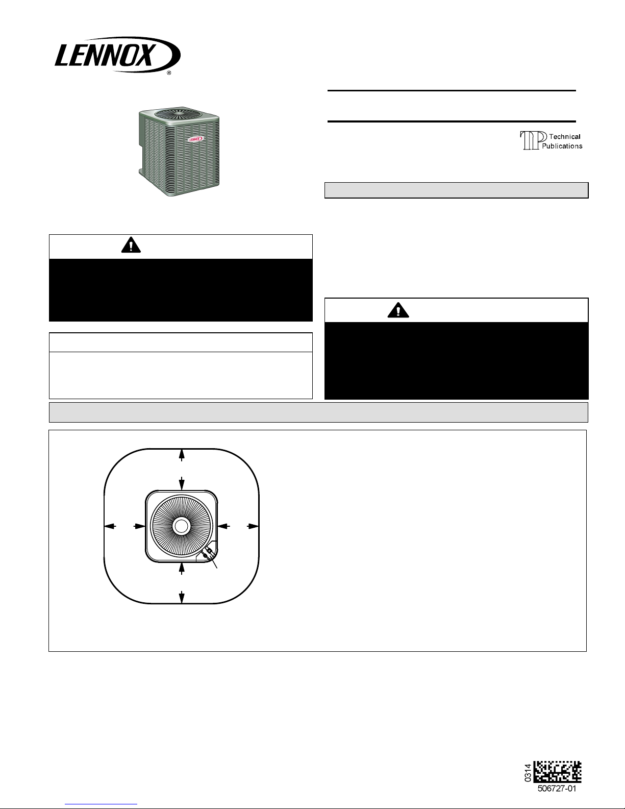
STEP 1 -- SETTING THE UNIT -- CLEARANCES
NOTES:
See
NOTES
See NOTES
See NOTES
See
NOTES
CONTROL
BOX
Service clearance of 30 in. (762 mm) must be maintained on
one of the sides adjacent to the control box.
Clearance to one of the other three sides must be 36 in. (914
mm)
Clearance to one of the remaining two sides may be 12 in.
(305 mm) and the final side may be 6 in. (152 mm).
A clearance of 24 in. must be maintained between two units.
48 in. (1219 mm) clearance required on top of unit.
FIGURE 1
Page 1
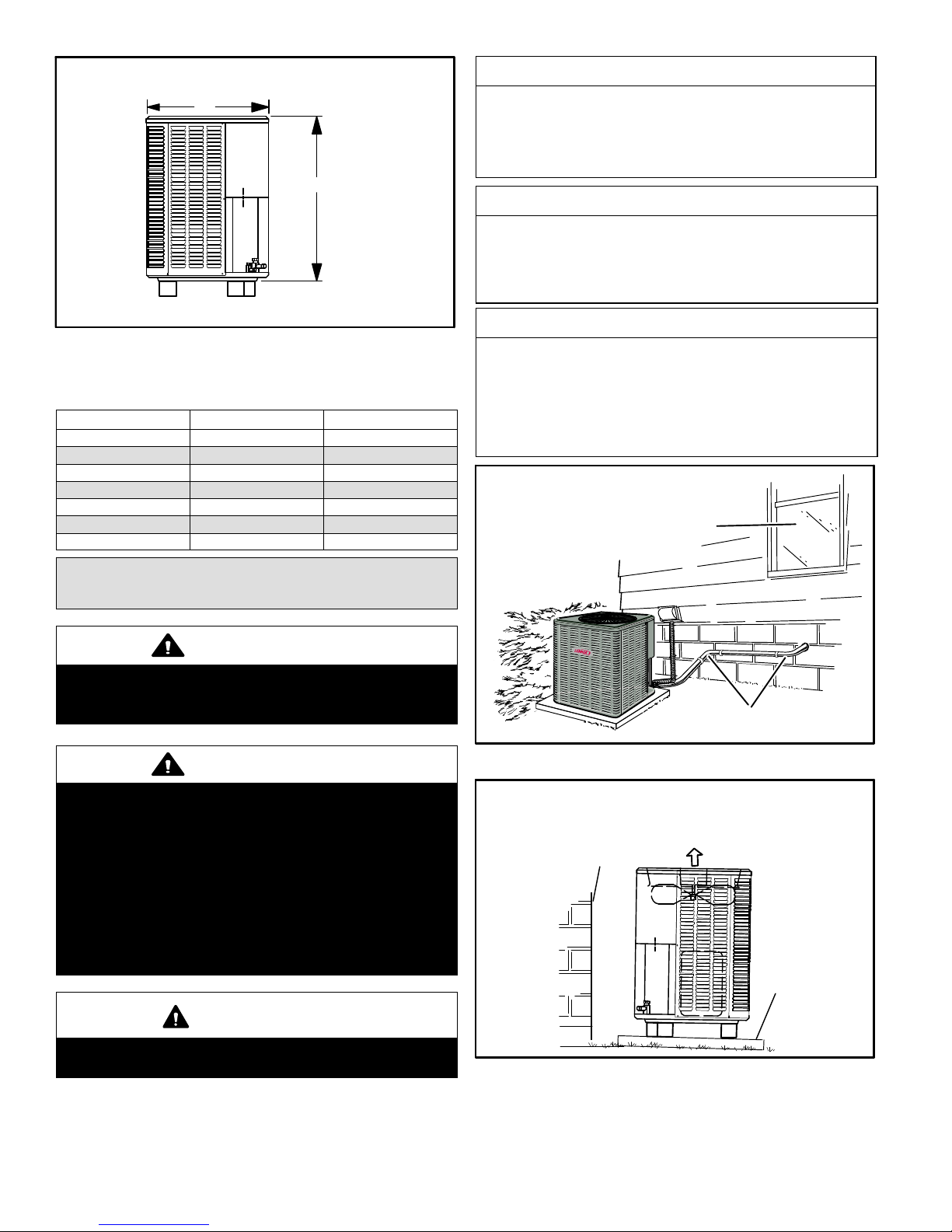
UNIT DIMENSIONS - INCHES (MM)
A
B
SIDE
VIEW
FIGURE 2
TABLE 1
UNIT DIMENSIONS
Model No. A B
13HPX-018-230 24-1/4 (616) 33-1/4 (845)
13HPX-024-230 24-1/4 (616) 33-1/4 (845)
13HPX-030-230 28-1/4 (718) 29-1/4 (743)
13HPX-036-230 28-1/4 (718) 37-1/4 (946)
13HPX-042-230 28-1/4 (718) 43-1/4 (1099)
13HPX-048-230 28‐1/4 (718) 33-1/4 (845)
13HPX-060-230 28‐1/4 (718) 37-1/4 (946)
NOTICE !
Roof Damage!
This system contains both refrigerant and oil. Some
rubber roofing material may absorb oil, causing the
rubber to degrade. Failure to follow this notice could
result in damage to roof surface.
IMPORTANT !
This model is designed for use in check / expansion
valve systems only. An indoor expansion valve ap
proved for use with HFC-410A refrigerant must be or
dered separately and installed prior to operating the
system.
IMPORTANT !
Exhaust vents from dryers, water heaters and furnaces
should be directed away from the outdoor unit. Pro
longed exposure to exhaust gases and the chemicals
contained within them may cause condensation to
form on the steel cabinet and other metal components
of the outdoor unit. This will diminish unit performance
and longevity.
PLACEMENT
INSTALL UNIT AWAY
FROM WINDOWS
STEP 1 -- SETTING THE UNIT
(CONTINUED) -- Unit Placement
CAUTION
As with any mechanical equipment, contact with sharp
sheet metal edges can result in personal injury. Take care
while handling this equipment.
WARNING
To prevent personal injury, as well as damage to panels,
unit or structure, observe the following:
While installing or servicing this unit, carefully stow all
removed panels so that the panels will not cause injury to
personnel, objects or nearby structures. Also, take care to
store panels where they will not be subject to damage
(e.g., being bent or scratched).
While handling or stowing the panels, consider any
weather conditions (especially wind) that may cause
panels to be blown around and damaged.
CAUTION
Before attempting to perform any service or maintenance,
turn the electrical power to unit OFF at disconnect switch.
TWO 90_ ELBOWS INSTALLED IN LINE SET
WILL REDUCE LINE SET VIBRATION
FIGURE 3
SLAB MOUNTING
Install unit level or, if on a slope, maintain slope tolerance of 2 degrees
(or 2 inches per 5 feet [50 mm per 1.5 m]) away from building structure.
BUILDING
STRUCTURE
DISCHARGE AIR
MOUNTING
SLAB
GROUND LEVEL
FIGURE 4
Page 2
STEP 2 -- REFRIGERANT PIPING -- Flush
ing Existing Line Set and Indoor Coil
Flush the existing line set per the following
instructions. For more information, refer to the
Installation and Service Procedures manual available
on DaveNet. CAUTION - DO NOT attempt to flush and
re-use existing line sets or indoor coil when the system
contains contaminants (i.e., compressor burn out).
NOTE - When installing refrigerant lines longer than 50 feet,
refer to the Refrigerant Piping Design and Fabrication
Guidelines manual available on DaveNet (Corp. 9351-L9),
or contact the Technical Support Department Product
Application group for assistance.
TABLE 2
REFRIGERANT LINE SET — INCHES (MM)
Field
Model
-018
-024
-030
-036
-042
-048
-060
NOTE — Some applications may required a field provided 7/8” to 1-1/8”
adapter
Connections
Liquid
Line
3/8 in.
(10
mm)
3/8 in.
(10
mm)
3/8 in.
(10
mm)
Vapor
Line
3/4 in.
(19
mm)
7/8 in.
(22
mm)
1-1/8
in. (29
mm)
Recommended Line Set
Liquid
Line
3/8 in.
(10
mm)
3/8 in.
(10
mm)
3/8 in.
(10
mm)
Vapor
Line
3/4 in.
(19
mm)
7/8 in.
(22
mm)
1-1/8
in. (29
mm)
L15 Line Sets
L15-41 — 15 ft. 50 ft. (4.6 m - 15
m)
L15-65 — 15 ft. 50 ft. (4.6 m - 15
m)
Field Fabricated
IMPORTANT !
If this unit is being matched with an approved line set
or indoor unit coil that was previously charged with
mineral oil, or if it is being matched with a coil which
was manufactured before January of 1999, the coil
and line set must be flushed prior to installation. Take
care to empty all existing traps. Polyol ester (POE)
oils are used in Lennox units charged with HFC-410A
refrigerant. Residual mineral oil can act as an insula
tor, preventing proper heat transfer. It can also clog
the expansion device and reduce system perfor
mance and capacity.
Failure to properly flush the system per this instruc
tion and the detailed Installation and Service Proce
dures manual will void the warranty.
WARNING
When using a high pressure gas such as
nitrogen to pressurize a refrigeration or air
conditioning system, use a regulator that
can control the pressure down to 1 or 2 psig
(6.9 to 13.8 kPa).
WARNING
Refrigerant can be harmful if it is inhaled. Refrigerant
must be used and recovered responsibly.
Failure to follow this warning may result in personal injury
or death.
WARNING
Fire, Explosion and Personal Safety Haz
ard. Failure to follow this warning could re
sult in damage, personal injury or death.
Never use oxygen to pressurize or purge re
frigeration lines. Oxygen, when exposed to
a spark or open flame, can cause fire and/or
an explosion, that could result in property
damage, personal injury or death.
WARNING
Polyol ester (POE) oils used with HFC-410A
refrigerant absorb moisture very quickly. It is very
important that the refrigerant system be kept closed as
much as possible. DO NOT remove line set caps or
service valve stub caps until you are ready to make
connections.
IMPORTANT !
Some scroll compressors have an internal vacuum
protector that will unload scrolls when suction pres
sure goes below 20 psig. A hissing sound will be
heard when the compressor is running unloaded.
Protector will reset when low pressure in system is
raised above 40 psig. DO NOT REPLACE COMPRES
SOR.
Page 3
13HPX SERIES
LINE SET INSTALLATION
IMPORTANT — Refrigerant lines must not contact structure.
Line Set Isolation — The following illustrations are
examples of proper refrigerant line set isolation:
REFRIGERANT LINE SET — TRANSITION
FROM VERTICAL TO HORIZONTAL
ANCHORED HEAVY NYLON
WIRE TIE OR AUTOMOTIVE
MUFFLER‐TYPE HANGER
WALL
STUD
NON-CORROSIVE
METAL SLEEVE
AUTOMOTIVE
MUFFLER‐TYPE HANGER
STRAP LIQUID LINE TO
VAPOR LINE
LIQUID LINE
VAPOR LINE - WRAPPED
IN ARMAFLEX
REFRIGERANT LINE SET — INSTALLING
VERTICAL RUNS (NEW CONSTRUCTION SHOWN)
NOTE — Insulate liquid line when it is routed through areas where the
surrounding ambient temperature could become higher than the
temperature of the liquid line or when pressure drop is equal to or greater
than 20 psig.
IMPORTANT — Refrigerant lines must not contact wall
OUTSIDE WALL
WOOD BLOCK
BETWEEN STUDS
VAPOR LINE
LIQUID LINE
WIRE TIE
INSIDE WALL
STRAP
NON-CORROSIVE
METAL SLEEVE
WIRE TIE
WOOD BLOCK
WIRE TIE
STRAP
REFRIGERANT LINE SET — INSTALLING
HORIZONTAL RUNS
To hang line set from joist or rafter, use either metal strapping material
or anchored heavy nylon wire ties.
WIRE TIE (AROUND
VAPOR LINE ONLY)
8 FEET (2.43 METERS)
STRAPPING
MATERIAL (AROUND
VAPOR LINE ONLY)
FLOOR JOIST OR
ROOF RAFTER
TAPE OR
WIRE TIE
FLOOR JOIST OR
ROOF RAFTER
8 FEET (2.43 METERS)
NON-CORROSIVE
METAL SLEEVE
STRAP THE VAPOR LINE TO THE JOIST
OR RAFTER AT 8 FEET (2.43 METERS)
INTERVALS THEN STRAP THE LIQUID
LINE TO THE VAPOR LINE.
TAPE OR
WIRE TIE
SLEEVE
VAPOR LINE WRAPPED
WITH ARMAFLEX
OUTSIDE
PVC
PIPE
WALL
FIBERGLASS
INSULATION
CAULK
LIQUID
LINE
NOTE — Similar installation practices should be used if line set is
to be installed on exterior of outside wall.
FIGURE 5
Page 4
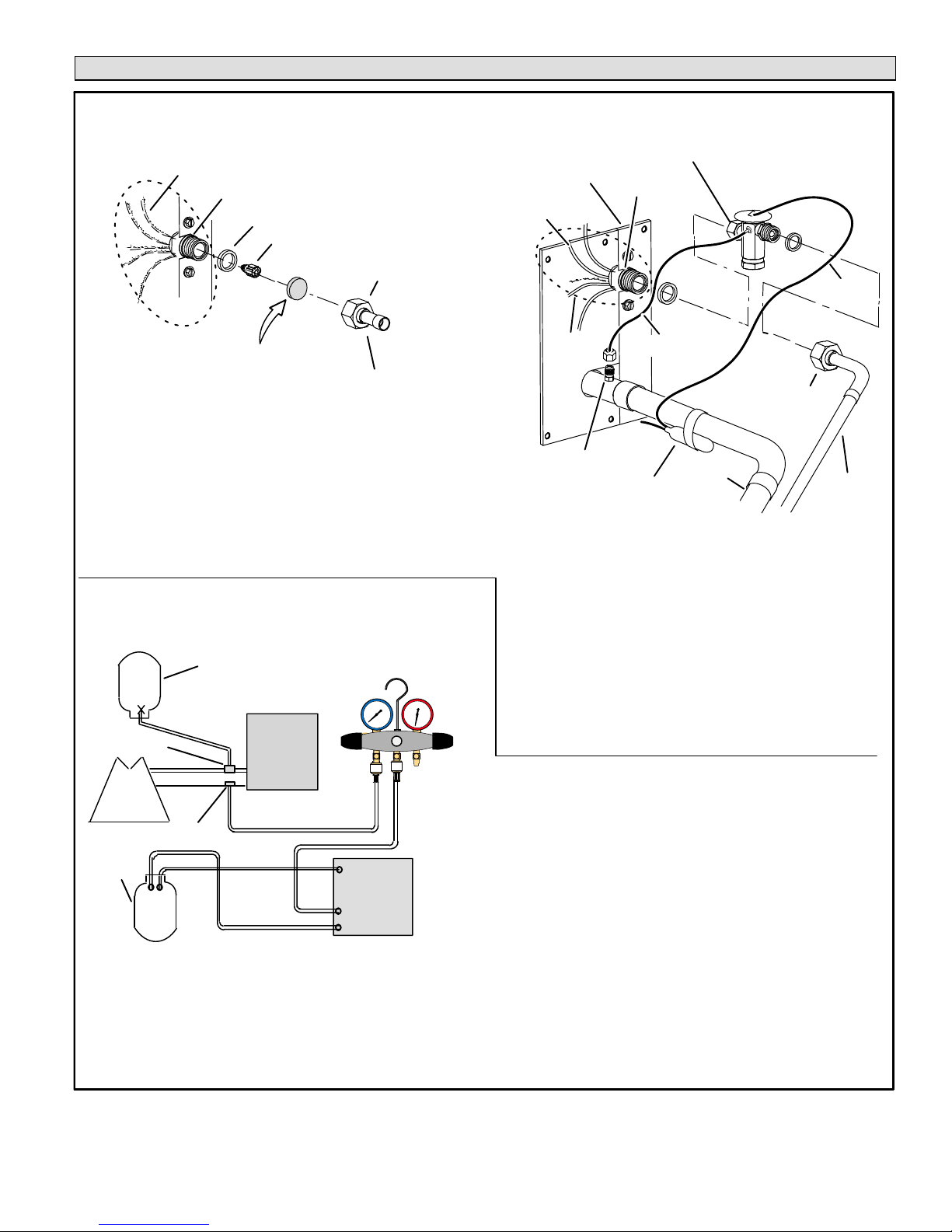
STEP 2 -- REFRIGERANT PIPING -- Removing Existing Indoor Metering Device
TYPICAL EXISTING FIXED ORIFICE
1A
DISTRIBUTOR
ASSEMBLY
A. On fully cased coils, remove the coil access and plumbing panels.
B. Remove any shipping clamps from the liquid line and distributor as
sembly.
C. Using two wrenches, disconnect liquid line from liquid line orifice hous
ing. Take care not to twist or damage distributor tubes during this pro
cess.
D. Remove and discard fixed orifice, valve stem assembly (if present)
and Teflon® washer as illustrated above.
E. Use a field-provided fitting to temporarily reconnect the liquid line to the
indoor unit's liquid line orifice housing.
(UNCASED COIL SHOWN)
DISTRIBUTOR TUBES
LIQUID LINE ORIFICE HOUSING
TEFLON® RING
FIXED ORIFICE
REMOVE AND DISCARD
WHITE TEFLON
(IF PRESENT)
®
SEAL
LIQUID LINE ASSEMBLY
(INCLUDES STRAINER)
REMOVAL PROCEDURE
OR
BRASS NUT
1B
TWO-PIECE PATCH PLATE
CONNECT GAUGES AND EQUIPMENT FOR
FLUSHING PROCEDURE
2
CYLINDER CONTAINING
CLEAN HCFC-22 TO BE
USED FOR FLUSHING
(Positioned to deliver liquid
A
refrigerant)
1
VAPOR LINE
SERVICE VALVE
EXISTING
INDOOR
UNIT
LIQUID LINE SERVICE
VALV E
RECOVERY
CYLINDER
VAPOR
LIQUID
OUTDOOR
B
NEW
UNIT
OPENED
C
D
RECOVERY MACHINE
A. HCFC-22 cylinder with clean refrigerant (positioned to deliver liquid
refrigerant) to the vapor service valve.
B. HCFC-22 gauge set (low side) to the liquid line valve.
C. HCFC-22 gauge set center port to inlet on the recovery machine with an
empty recovery tank connected to the gauge set.
D. Connect recovery tank to recovery machine per machine instructions.
GAUGE
MANIFOLD
LOW HIGH
CLOSED
TANK
RETURN
INLET
DISCHARGE
TYPICAL EXISTING EXPANSION VALVE REMOVAL
PROCEDURE (UNCASED COIL SHOWN)
ORIFICE
HOUSING
EQUALIZER
LINE
STUB END
TEFLON
RING
VAPOR
CHECK
EXPANSION
VALV E
®
LIQUID LINE
ASSEMBLY WITH
BRASS NUT
LINE
TEFLON
(UNCASED COIL ONLY)
DISTRIBUTOR
TUBES
DISTRIBUTOR
ASSEMBLY
MALE EQUALIZER
LINE FITTING
A. On fully cased coils, remove the coil access and plumbing panels.
B. Remove any shipping clamps from the liquid line and distributor
assembly.
C. Disconnect the equalizer line from the check expansion valve
equalizer line fitting on the vapor line.
D. Remove the vapor line sensing bulb.
E. Disconnect the liquid line from the check expansion valve at the
liquid line assembly.
F. Disconnect the check expansion valve from the liquid line orifice
housing. Take care not to twist or damage distributor tubes during
this process.
G. Remove and discard check expansion valve and the two Teflon
rings.
H. Use a field-provided fitting to temporarily reconnect the liquid line
to the indoor unit's liquid line orifice housing.
LIQUID LINE
SENSING BULB
FLUSHING LINE SET
The line set and indoor unit coil must be flushed with at least the same
3
amount of clean refrigerant that previously charged the system. Check
the charge in the flushing cylinder before proceeding.
A. Set the recovery machine for liquid recovery and start the
recovery machine. Open the gauge set valves to allow the
recovery machine to pull a vacuum on the existing system line
B
set and indoor unit coil.
B. Position the cylinder of clean HCFC-22 for delivery of liquid
refrigerant and open its valve to allow liquid refrigerant to flow
into the system through the vapor line valve. Allow the refrigerant
to pass from the cylinder and through the line set and the indoor
unit coil before it enters the recovery machine.
C. After all of the liquid refrigerant has been recovered, switch the
recovery machine to vapor recovery so that all of the HCFC-22
vapor is recovered. Allow the recovery machine to pull the
system down to 0.
D. Close the valve on the inverted HCFC-22 drum and the gauge
set valves. Pump the remaining refrigerant out of the recovery
machine and turn the machine off.
RING
®
SENSING
LINE
LIQUID
LINE
®
FIGURE 6
Page 5
13HPX SERIES
 Loading...