

Lennox Merit Series13ACD, 13ACD−018, 13ACD−024, 13ACD−030, 13ACD−036 Installation Instructions Manual
...
INSTALLATION
2008 Lennox Industries Inc.
Dallas, Texas, USA
RETAIN THESE INSTRUCTIONS
FOR FUTURE REFERENCE
WARNING
Improper installation, adjustment, alteration,
service or maintenance can cause personal injury,
loss of life, or damage to property.
Installation and service must be performed by a
licensed professional installer (or equivalent) or a
service agency.
INSTRUCTIONS
Merit® Series13ACD Units
AIR CONDITIONER UNITS
505,366M
01/08
Supersedes 11/07
Table of Contents
Shipping and Packing List 1. . . . . . . . . . . . . . . . . . . . . .
13ACD Outdoor Unit 1. . . . . . . . . . . . . . . . . . . . . . . . . . .
Unit Dimensions 2. . . . . . . . . . . . . . . . . . . . . . . . . . . . . . .
General Information 2. . . . . . . . . . . . . . . . . . . . . . . . . . .
Recovering Refrigerant from Existing System 4. . . . .
Removing Existing Outdoor Unit 5. . . . . . . . . . . . . . . . .
Positioning New Outdoor Unit 5. . . . . . . . . . . . . . . . . . .
New or Replacement Line Set 6. . . . . . . . . . . . . . . . . . .
Brazing Connections 8. . . . . . . . . . . . . . . . . . . . . . . . . . .
Removing Indoor Unit Metering Device 9. . . . . . . . . . . .
Installing New Indoor Unit Metering Device 9. . . . . . . .
Testing for Leaks 11. . . . . . . . . . . . . . . . . . . . . . . . . . . . . .
Evacuating the System 12. . . . . . . . . . . . . . . . . . . . . . . . .
Servicing Unit Delivered Void of Charge 13. . . . . . . . . . .
Electrical Connections 13. . . . . . . . . . . . . . . . . . . . . . . . .
Start−Up and Charging Procedures 14. . . . . . . . . . . . . . .
System Operation 18. . . . . . . . . . . . . . . . . . . . . . . . . . . . .
Maintenance 18. . . . . . . . . . . . . . . . . . . . . . . . . . . . . . . . . .
Homeowner Information 19. . . . . . . . . . . . . . . . . . . . . . . .
Start−Up and Performance Checklist 20. . . . . . . . . . . . .
Litho U.S.A.
CAUTION
Physical contact with metal edges and corners
while applying excessive force or rapid motion can
result in personal injury. Be aware of, and use
caution when working near these areas during
installation or while servicing this equipment.
IMPORTANT
The Clean Air Act of 1990 bans the intentional
venting of refrigerant (CFCs, HCFCs AND HFCs) as
of July 1, 1992. Approved methods of recovery,
recycling or reclaiming must be followed. Fines
and/or incarceration may be levied for
noncompliance.
Shipping and Packing List
Check the unit for shipping damage and listed times below
are intact. If damaged, or if parts are missing, immediately
contact the last shipping carrier.
1 Assembled outdoor unit
1 Refrigerant flow control kit (Fixed Orifice)
13ACD Outdoor Unit
13ACD Air Conditioners, which will also be referred to in
this instruction as the outdoor unit, uses HCFC−22
refrigerant. This outdoor unit must be installed with a
matching indoor unit and line set as outlined in the Lennox
13ACD Engineering Handbook.
This outdoor unit is designed for use in systems that use
one of the following refrigerant metering devices:
Thermal expansion valve (TXV)
Fixed orifice
01/08 505,366M
*2P0108* *P505366M*
Page 1
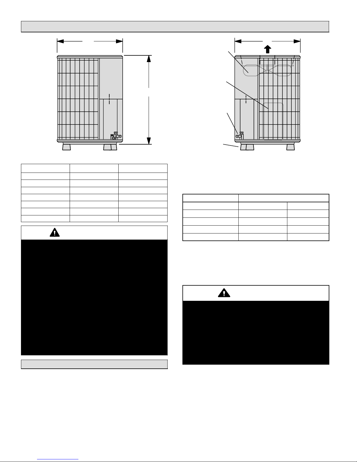
Unit Dimensions − inches (mm)
A
B
SIDE VIEW
Model Number A B
13ACD−018 24−1/4 (616) 25−1/4 (641)
13ACD−024 24−1/4 (616) 25−1/4 (641)
13ACD−030 24−1/4 (616) 33−1/4 (845)
13ACD−036 24−1/4 (616) 33−1/4 (845)
13ACD−042 28−1/4 (718) 29−1/4 (743)
13ACD−048 28-1/4 (718) 37−1/4 (946)
13ACD−060 28-1/4 (718) 33−1/4 (845)
WARNING
This product and/or the indoor unit it is matched
with may contain fiberglass wool.
Disturbing the insulation during installation,
maintenance, or repair will expose you to fiberglass
wool dust. Breathing this may cause lung cancer.
(Fiberglass wool is known to the State of California
to cause cancer.)
Fiberglass wool may also cause respiratory, skin,
and eye irritation.
To reduce exposure to this substance or for further
information, consult material safety data sheets
available from address shown below, or contact
your supervisor.
Lennox Industries Inc.
P.O. Box 799900
Dallas, TX 75379−9900
General Information
These instructions are intended as a general guide and do
not supersede local codes in any way. Consult authorities
who have jurisdiction before installation.
A
OUTDOOR COIL FAN
COMPRESSOR
SUCTION AND LIQUID LINE
OPTIONAL UNIT STAND-OFF KIT
CONNECTIONS
(4) (FIELD−INSTALLED)
Discharge Air
SIDE VIEW
When servicing or repairing HVAC components, ensure
caps and fasteners are appropriately tightened. Table 1
lists torque values for typical service and repair items.
Table 1. Torque Requirements
Part Recommended Torque
Service valve cap 8 ft.− lb. 11 NM
Sheet metal screws 16 in.− lb. 2 NM
Machine screws #10 28 in.− lb. 3 NM
Compressor bolts 90 in.− lb. 10 NM
Gauge port seal cap 8 ft.− lb. 11 NM
USING MANIFOLD GAUGE SETS
When checking the system charge, use a manifold gauge
set that features low−loss anti−blow back fittings. See figure
1 for a typical manifold gauge connection setup.
OPERATING SERVICE VALVES
IMPORTANT
Only use Allen wrenches of sufficient hardness
(50Rc − Rockwell Harness Scale minimum). Fully
insert the wrench into the valve stem recess.
Service valve stems are factory−torqued (from 9
ft−lbs for small valves, to 25 ft−lbs for large valves) to
prevent refrigerant loss during shipping and
handling. Using an Allen wrench rated at less than
50Rc risks rounding or breaking off the wrench, or
stripping the valve stem recess.
The liquid and suction line service valves are typically used
for removing refrigerant, flushing, leak testing, evacuating,
checking charge and charging.
505366M 01/08
Page 2
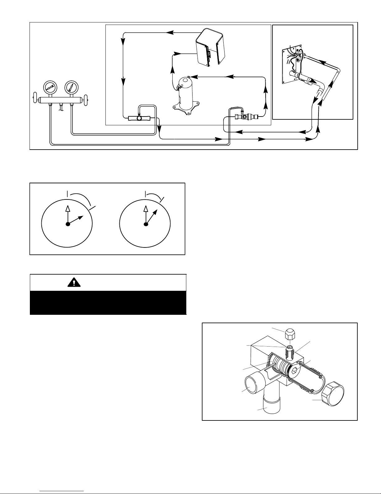
OUTDOOR UNIT
(Uncased Coil Shown)
LOW
PRESSURE
GAUGE MANIFOLD
PRESSURE
TO
HFC−410A
DRUM
HIGH
LIQUID LINE
SERVICE VALVE
COMPRESSOR
Figure 1. Typical Manifold Gauge Connection Setup
Each valve is equipped with a service port which has a
factory−installed valve stem.
1/12 TURN
12
1
2
3
4
7
5
6
9
10
8
11
1/6 TURN
12
1
2
3
4
7
5
6
11
10
9
8
Figure 2. Cap Tightening Distances
IMPORTANT
To prevent stripping of the various caps used, the
appropriately sized wrench should be used and
fitted snugly over the cap before tightening.
Operating Angle−Type Service Valve
To Access Angle−Type Service Port:
A service port cap protects the service port core from
contamination and serves as the primary leak seal.
1. Remove service port cap with an appropriately sized
wrench.
2. Connect gauge to the service port.
3. When testing is completed, replace service port cap and
tighten as follows:
With Torque Wrench: Finger tighten and then
tighten per table 1.
Without Torque Wrench: Finger tighten and use an
appropriately sized wrench to turn an additional
1/6 turn clockwise as illustrated in figure 2.
OUTDOOR
COIL
SUCTION LINE
SERVICE VALVE
TXV OR FIXED
ORIFICE
To Open and Close Angle−Type Service Valve:
A valve stem cap protects the valve stem from
contamination and assures a leak−free seal.
1. Remove stem cap with an appropriately sized wrench.
2. Use a service wrench with a hex−head extension
(3/16" for liquid-line valve sizes and 5/16" for
suction-line valve sizes) to back the stem out
counterclockwise as far as it will go.
3. Replace the stem cap and tighten as follows:
With Torque Wrench: Tighten finger tight and then
tighten per table 1.
Without Torque Wrench: Finger tighten and use an
appropriately sized wrench to turn an additional
1/12 turn clockwise as illustrated in figure 2.
NOTE − A label with specific torque requirements may be
affixed to the stem cap. If the label is present, use the
specified torque.
NOTE− To prevent stripping of the cap, the wrench should
be appropriately sized and fit snugly over the cap before
tightening the cap.
SERVICE PORT CAP
STEM CAP
SERVICE PORT
(VALVE STEM SHOWN
CLOSED) INSERT HEX
WRENCH HERE
SERVICE PORT
CLOSED TO BOTH
INDOOR AND
OUTDOOR UNITS
VALVE STEM
FRONT-SEATED
TO INDOOR
UNIT
TO OUTDOOR UNIT
Figure 3. Angle−Type Service Valve
CORE
(Font−Seated Closed)
Page 3
13ACD SERIES
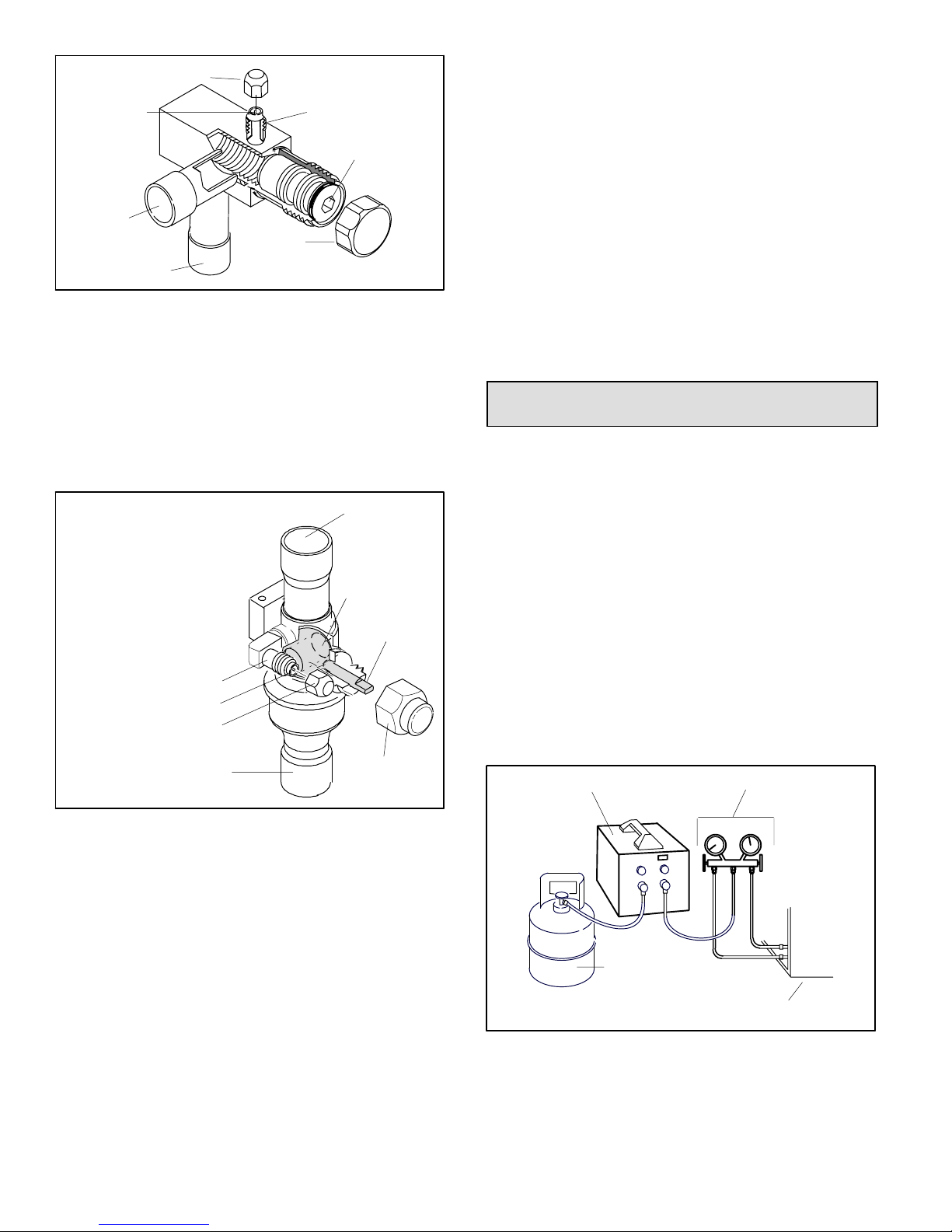
SERVICE PORT CAP
SERVICE PORT
CORE
OPEN TO BOTH
INDOOR AND
OUTDOOR UNITS
TO INDOOR
UNIT
TO OUTDOOR UNIT
STEM CAP
SERVICE PORT
(VALVE STEM SHOWN OPEN)
INSERT HEX WRENCH HERE
Figure 4. Angle−Type Service Valve
(Back−Seated Opened)
Operating Ball−Type Service Valve
To Access Ball−Type Service Port:
A service port cap protects the service port core from
contamination and serves as the primary leak seal.
OPEN TO LINE SET WHEN VALVE IS CLOSED,
TO BOTH LINE SET AND UNIT WHEN VALVE IS
OPEN.
TO OPEN ROTATE STEM
COUNTERCLOCKWISE 90°.
TO CLOSE ROTATE STEM
CLOCKWISE 90°.
SERVICE PORT
SERVICE PORT
CORE
SERVICE PORT CAP
TO OUTDOOR UNIT
TO INDOOR UNIT
BALL (SHOWN
CLOSED)
VALV E
STEM
STEM CAP
To Open and Close Ball−Type Service Valve:
A valve stem cap protects the valve stem from
contamination and assures a leak−free seal.
1. Remove stem cap with a wrench.
2. Use an appropriately sized wrench to open. To open
valve, rotate stem counterclockwise 90°. To close
rotate stem clockwise 90°.
3. Replace the stem cap and tighten as follows:
With Torque Wrench: Finger tighten and then
tighten per table 1.
Without Torque Wrench: Finger tighten and use an
appropriately sized wrench to turn an additional
1/12 turn clockwise as illustrated in figure 2.
NOTE − A label with specific torque requirements may be
affixed to the stem cap. If the label is present, use the
specified torque.
Recovering Refrigerant from Existing
System
Remove existing HCFC−22 refrigerant using one of the
following methods:
METHOD 1:
Use this method if the existing outdoor unit is not equipped
with manual shut−off valves, and plan on using existing
HCFC−22 refrigerant to flush the system.
NOTE − Use recovery machine instructions for specific
setup requirements.
Perform the following task:
1. Disconnect all power to the existing outdoor unit.
2. Connect to the existing unit a gauge set, clean
recovery cylinder and a recovery machine. Use the
instructions provided with the recover machine on how
to setup the connections.
3. Remove all HCFC−22 refrigerant from the existing
system. Check gauges after shutdown to confirm that
the entire system is completely void of refrigerant.
RECOVERY MACHINE
MANIFOLD GAUGES
Figure 5. Ball−Type Service Valve
1. Remove service port cap with an appropriately sized
wrench.
2. Connect gauge to the service port.
3. When testing is completed, replace service port cap and
tighten as follows:
With Torque Wrench: Finger tighten and then
tighten per table table 1.
Without Torque Wrench: Finger tighten and use an
appropriately sized wrench to turn an additional
1/6 turn clockwise as illustrated in figure 2.
505366M 01/08
Page 4
CLEAN RECOVERY
CYLINDER
OUTDOOR UNIT
Figure 6. Typical Refrigerant Recovery (Method 1)
METHOD 2:
Use this method if the existing outdoor unit is equipped
with manual shut−off valves, and plan on using new
HCFC−22 refrigerant to flush the system.
IMPORTANT: Some system configurations may contain
higher than normal refrigerant charge due to either large
internal coil volumes, and/or long line sets. The following
conditions may cause the compressor to stop functioning:
The following devices could prevent full system charge
recovery into the outdoor unit:
Outdoor unit’s high or low−pressure switches if tripped
can cycled the compressor OFF.
Compressor can stop pumping due to tripped internal
pressure relief valve.
Compressor has internal vacuum protection that is
designed to unload the scrolls (compressor stops
pumping) when the pressure ratio meets a certain
value or when the suction pressure is as high as 20
psig. (Compressor suction pressures should never be
allowed to go into a vacuum. Prolonged operation at
low suction pressures will result in overheating of the
scrolls and permanent damage to the scroll tips, drive
bearings and internal seals).
Once the compressor can not pump down to a lower
pressure due to one of the above system conditions, shut
off the suction valve. Turn OFF the main power to unit and
use a recovery machine to recover any refrigerant left in
the indoor coil and line set.
Perform the following task:
1. Start the existing HCFC−22 system in the cooling
mode and close the liquid line valve.
2. Pump as much of the existing HCFC−22 refrigerant
with the compressor back into the outdoor unit until
you have reached the limitations of the outdoor
system. Turn the outdoor unit main power OFF and
use a recovery machine to remove the remaining
refrigerant in the system.
NOTE − It may be necessary to bypass the low pressure
switches if equipped to ensure complete refrigerant
evacuation.
3. When the low side system pressures reach 0 psig,
close the suction line valve.
4. Check gauges after shutdown to confirm that the
valves are not allowing refrigerant to flow back into the
low side of the system.
*
*
*
*
* SEE NOTES BELOW THIS FIGURE FOR FURTHER DETAILS.
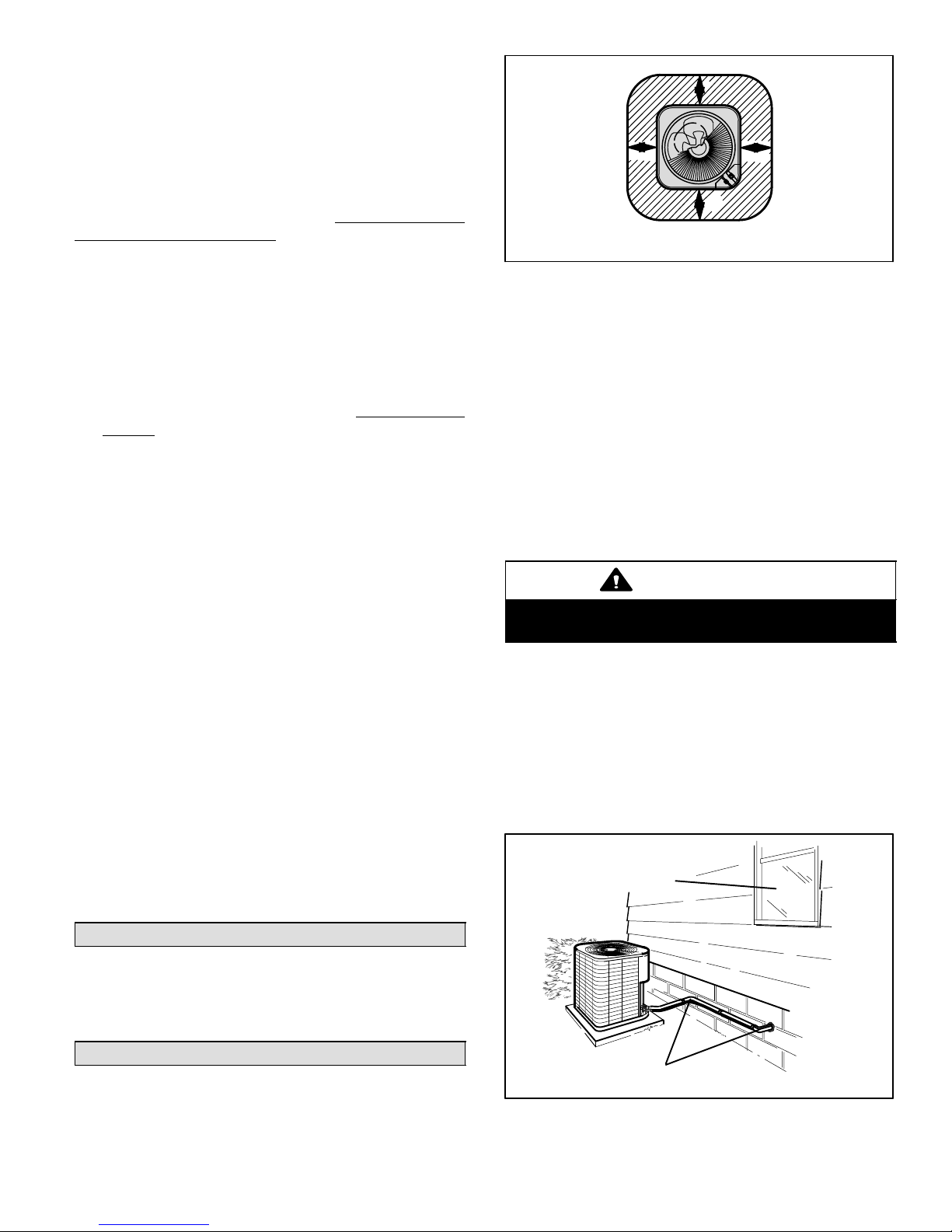
Figure 7. Installation Clearances
NOTES:
Service clearance of 30 in. (762 mm) must be
maintained on one of the sides adjacent to the control
box.
Clearance to one of the other three sides must be 36
in. (914 mm)
Clearance to one of the remaining two sides may be
12 in. (305 mm) and the final side may be 6 in. (152
mm)
48 in. (1219 mm) clearance required on top of unit.
A clearance of 24 in. (610 mm) must be maintained
between two units
POSITIONING CONSIDERATIONS
CAUTION
In order to avoid injury, take proper precaution when
lifting heavy objects.
Consider the following when positioning the unit:
Some localities are adopting sound ordinances based
on the unit’s sound level registered from the adjacent
property, not from the installation property. Install the
unit as far as possible from the property line.
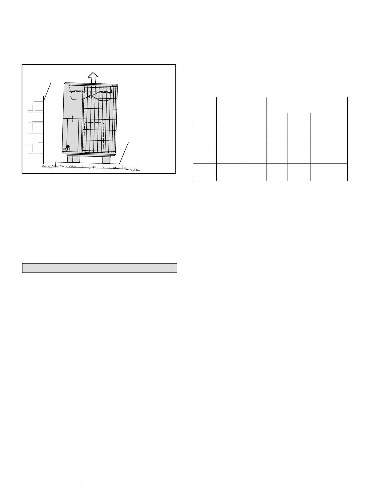
When possible, do not install the unit directly outside
a window. Glass has a very high level of sound
transmission. For proper placement of unit in relation
to a window see the provided illustration in figure 8.
INSTALL UNIT AWAY
FROM WINDOWS
Removing Existing Outdoor Unit
Perform the following task at the existing outdoor unit:
Disconnect line set at the service valves.
Disconnect electrical service at the disconnect switch.
Remove old outdoor unit.
Positioning New Outdoor Unit
See Unit Dimensions on page 2 to sizing mounting slab,
platforms or supports. Refer to figure 7 for mandatory
installation clearance requirements.
Page 5
TWO 90° ELBOWS INSTALLED
IN LINE SET WILL REDUCE
LINE SET VIBRATION.
Figure 8. Outside Unit Placement
13ACD SERIES
PLACING OUTDOOR UNIT ON SLAB
When installing a unit at grade level, the top of the slab
should be high enough above the grade so that water from
higher ground would not collect around the unit as
illustrated in figure 9.
BUILDING
STRUCTURE
DISCHARGE AIR
MOUNTING
SLAB
GROUND LEVEL
Figure 9. Ground Level Slab Mounting
Slab may be level or have a slope tolerance away from the
building of not more than two degrees, or two inches per 5
feet (51 mm per 1524 mm) as illustrated in figure 9.
INSTALLING OUTDOOR UNIT ON ROOF
Install the unit a minimum of six inches (152 mm) above the
roof surface to avoid ice build−up around the unit. Locate
the unit above a load bearing wall or area of the roof that
can adequately support the unit. Consult local codes for
rooftop applications.
New or Replacement Line Set
This section provides information on new installation or
replacement of existing line set. If a new or replacement
line set is not required, then proceed to Brazing
Connections on page 8.
If refrigerant lines are routed through a wall, seal and
isolate the opening so vibration is not transmitted to the
building. Pay close attention to line set isolation during
installation of any HVAC system. When properly isolated
from building structures (walls, ceilings. floors), the
refrigerant lines will not create unnecessary vibration and
subsequent sounds.
Also, consider the following when placing and installing a
high−efficiency air conditioner:
REFRIGERANT LINE SET
Field refrigerant piping consists of liquid and suction lines
from the outdoor unit (braze connections) to the indoor unit
coil (flare or braze connections). Use Lennox L15 (braze,
non−flare) series line set, or use field−fabricated refrigerant
lines as listed in table 2.
Table 2. Refrigerant Line Set
Model
−018
−024
−030
−036
−042
−048
−060
Field
Connections
Liquid
Line
3/8 in.
(10 mm)
3/8 in.
(10 mm)
3/8 in.
(10 mm)
Suction
Line
3/4 in
(19 mm)
7/8 in
(22 mm)
1−1/8 in.
(29 mm)
Recommended Line Set
Liquid
Line
3/8 in.
(10
mm)
3/8 in.
(10
mm)
3/8 in.
(10
mm)
Suction
Line
3/4 in
(19 mm)
7/8 in
(22 mm)
1−1/8 in.
(29 mm)
L15
Line Sets
L15−41
15 ft. − 50 ft.
(4.6 m − 15 m)
L15−65
15 ft. − 50 ft.
(4.6 m − 15 m)
Field
Fabricated
NOTE − When installing refrigerant lines longer than 50
feet, contact Lennox Technical Support Product
Applications for assistance or Lennox piping manual. To
obtain the correct information from Lennox, be sure to
communicate the following points:
Model (13ACD) and size of unit (e.g. −060).
Line set diameters for the unit being installed as listed
in table 2 and total length of installation.
Number of elbows and if there is a rise or drop of the
piping.
MATCHING WITH NEW OR EXISTING INDOOR COIL
AND LINE SET
The RFC1−metering line consisted of a small bore copper
line that ran from condenser to evaporator coil. Refrigerant
was metered into the evaporator by utilizing
temperature/pressure evaporation effects on refrigerant in
the small RFC line. The length and bore of the RFC line
corresponded to the size of cooling unit.
If the 13ACD is being used with either a new or existing
indoor coil which is equipped with a liquid line which served
as a metering device (RFCI), the liquid line must be
replaced prior to the installation of the 13ACD unit.
Typically a liquid line used to meter flow is 1/4" in diameter
and copper.
505366M 01/08
Page 6
 Loading...