

Page 1
Service Manual
Lennox Electric Fireplaces
Merit Series
MPE36
MPE33
Page 2

Contents
• Removal Log Grate page 3
• Removal of Logs/Ember page 3
• Changing ember bul bs page 4
• Removal of glass panel page 5
• Component identification page 7
• Confirm power supply page 8
• Transformer testing page 9
• Flame panel removal page 11
• Flame cylinder bulb replacement page 12
• Lights: Flame and Ember page 13
• Electrical junction box access page 15
• Opti onal wall thermostat page 16
• Opti onal wall switch page 17
• Control board page 18
• Remote control sensor page 23
• Remote control feature page 24
• Heater thermostat operation page 24
• Flame cylinder motor replacement page 25
• Control panel sw itches page 29
• Remote control does not function page 31
• Heater sensor page 32
• Heater access page 33
• Testing the heater/blower page 34
• Junction box w iring page 42
• Parts List page 45
• Read this first
• This manual is provided as a
tool to assist professional
service personnel working on
Lennox Electric Fireplaces.
• Do not attempt to service this
electrical appliance if:
– You have not been trained
how to safely service
electrical appliances.
– You are not familiar w ith the
use of electrical diagnostic
tools.
• Disconnect the power supply
prior to attempting any service.
• Electrical Shock Hazard
• Read this manual and the
installation and operation
instructions for this appliance
before attempting any service.
• If you have any questions
regarding this appliance
contact Lennox Technical
Service at: (800) 655-2008
Page 3
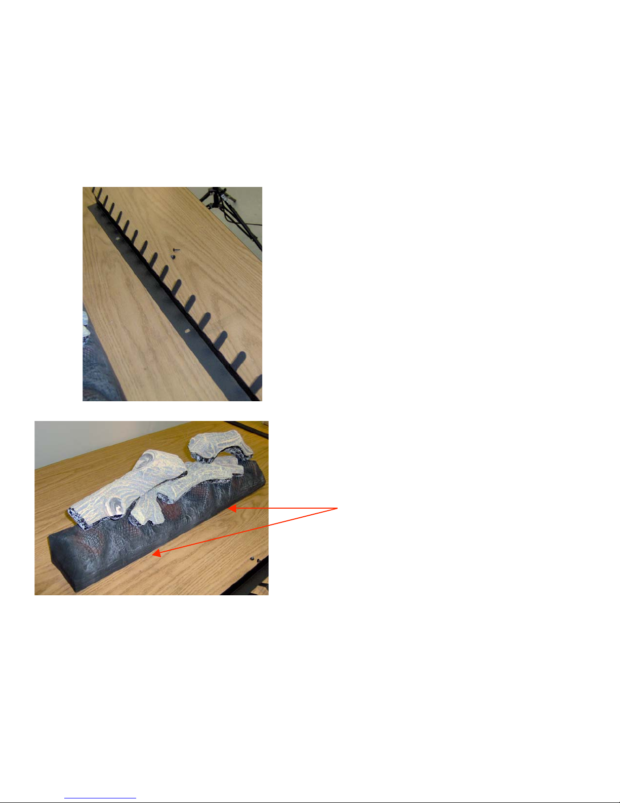
Remove Grate and Log
Set
• The grate must be removed
before removing the log set.
• Remove the two screws that
secure the grate in place
and remove the grate.
• Place your thumbs on the
front edge of the ember
base approximately 1/3 of
the way in from the ends of
the log set.
• Push towards the back
causing the ember base to
flex. As you push gently lift
the front edge of the ember
base. The log set and
ember base may be lifted up
and out of place.
Page 4

Changing ember bulbs
• Remove logs and grate
(see page 3)
• On MPE36R
replacement bulbs will be
found in a pocket in the
log set
• Lift at the front of the
plastic ember bed to
“pop” it up and release it.
• Remove ember bed.
• Remove spring retainer
from bulb.
• Remove defective bulb.
• Using plastic gloves or a
small plastic bag to
prevent oils from your
hands from coating the
bulbs, insert the
replacement bulb in the
socket and replace the
retaining spring.
• Replace ember bed
• Replace logs and grate.
Page 5
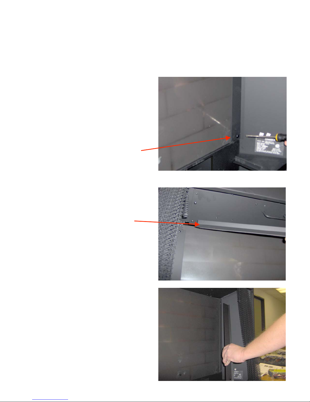
Removal of rear glass
panel
• Remove logs and grate
• Remove ember bed
• Remove screws from
right and left retaining
brackets
• Remove screws from top
retaining bracket
Caution: wear protective gloves
when removing or handling the
glass panel.
Gloves will help prevent cuts
and will also prevent the oils
from your hands from staining
the surface of the glass panel
Page 6
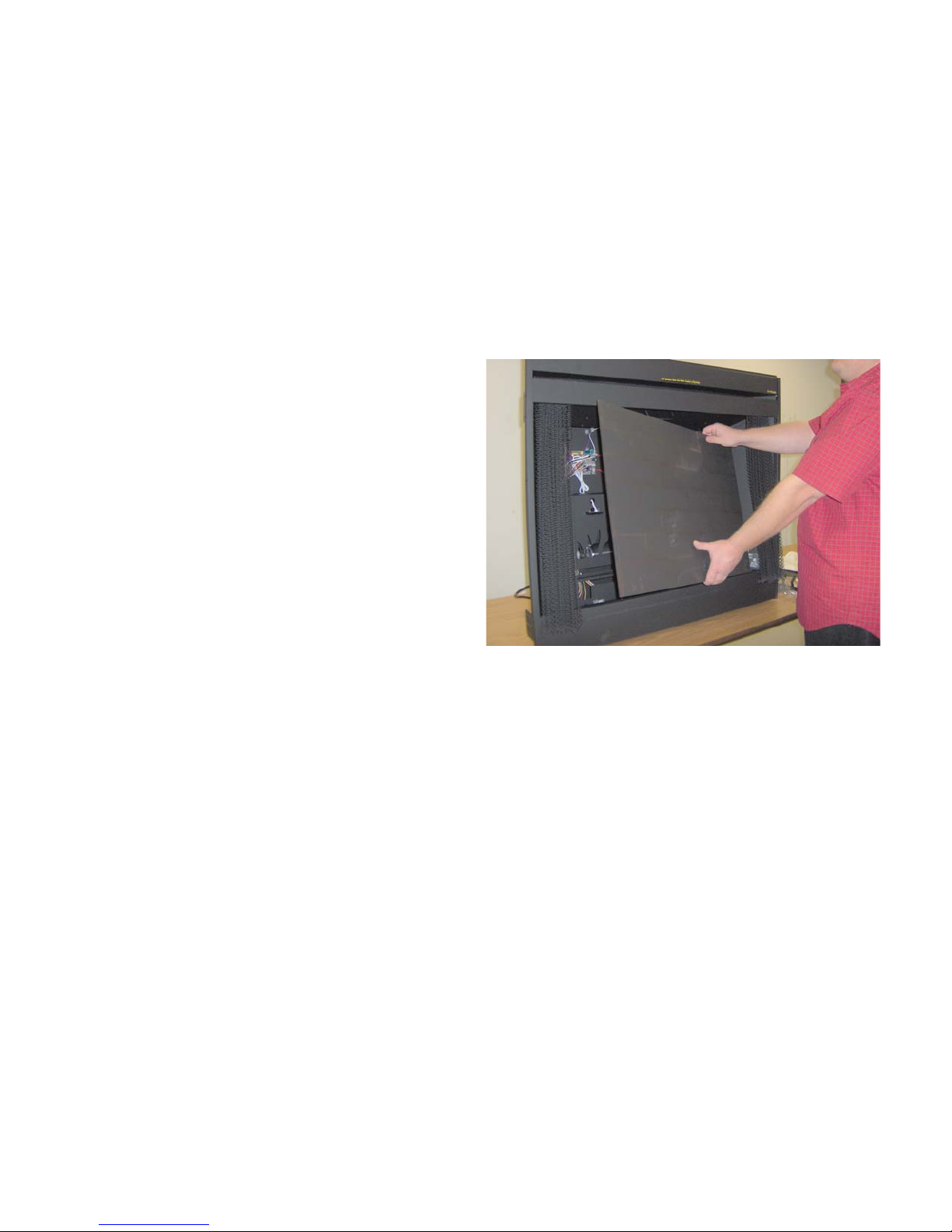
Removal of rear glass
panel (continued)
• Grasp glass panel at top
and tip forward.
• With panel loose, grasp
on top and bottom edges
to remove from fireplace.
Page 7
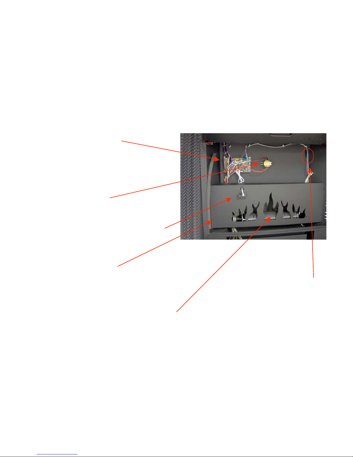
Components
• Control board
• Transformer
• Remote control receiver
• Flame cover panel
• Motor and Flame cylinder
Fuse location
Page 8
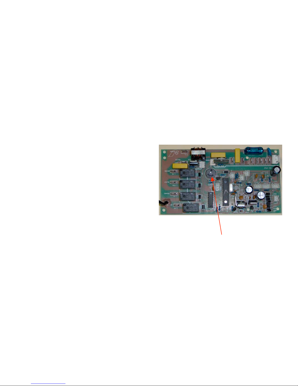
Power supply
• When the electric fireplace
is initially connected to a
power supply:
– By plugging in the power
cord to a receptacle
– By turning on the circuit
breaker (hard wired
connection at the junction
box)
• The control board will emit two
loud “beeps” to confirm
“power up”.
• If you do not hear these
‘beeps”:
– Confirm that the circuit
breaker is “on”
– Confirm power to the
receptacle.
– Is an external switch
controlling the power to the
fireplace? If so it must be on.
• If power is available to the
fireplace and the two “beeps”
are not sounded at”power up”,
look for:
– Transformer failure (page 9)
– Control board failure
Control Board- beeps twice
to confirm “power up”
Page 9
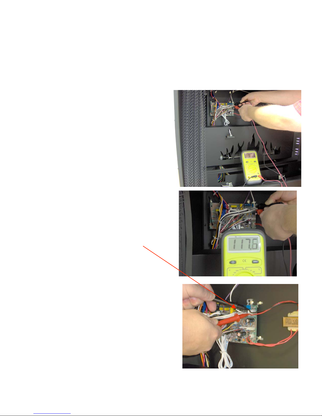
Testing Transformer
• Caution:
electrical
shock hazard!
• This tests confirms that
line voltage 120 VAC is
available to power the
transformer.
• Place multimeter leads
on control board
terminals as shown.
• Line voltage should be
between 105 VAC – 127
VAC.
Page 10
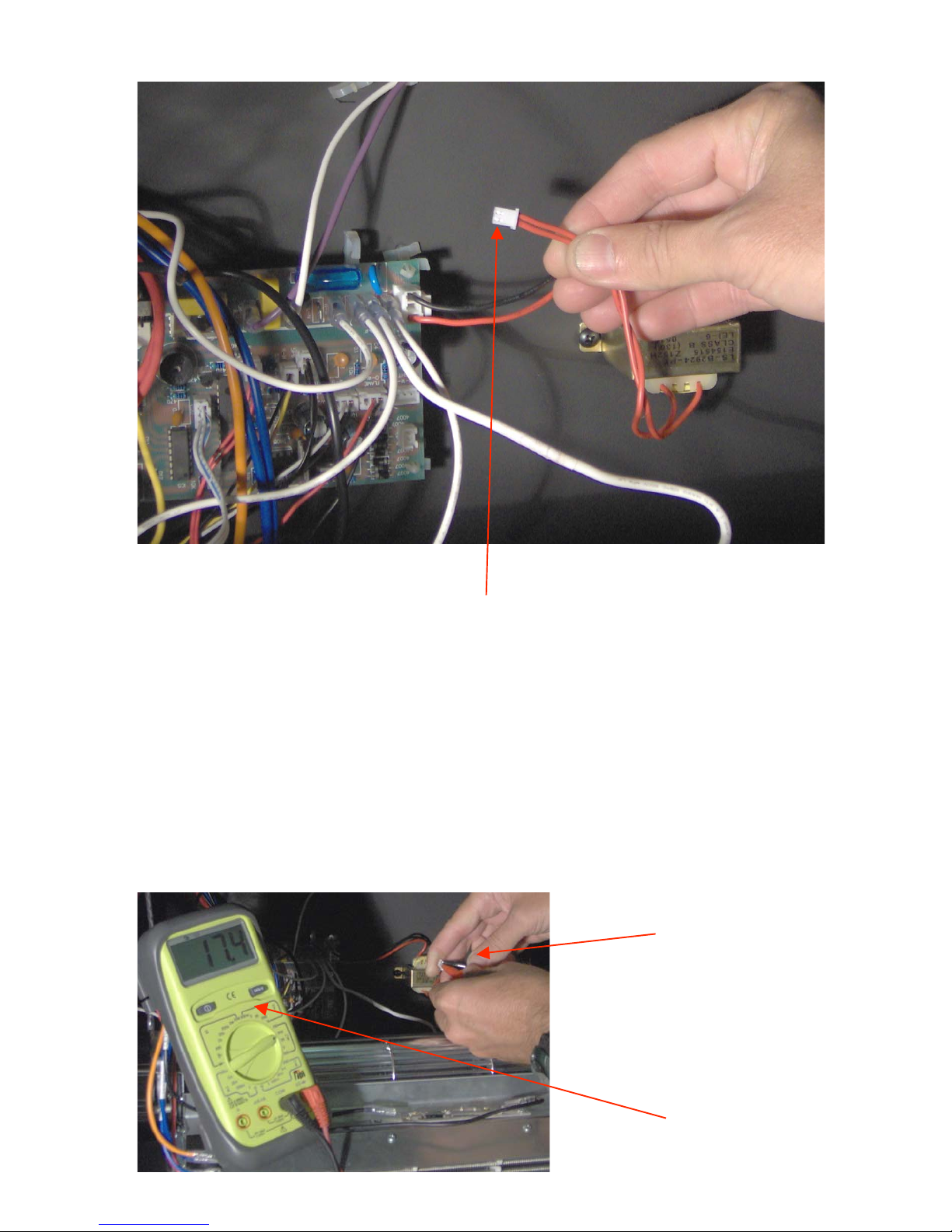
To test the transformer:
•Remove the low voltage connector (two red wires) from the control board as
shown. On the side of the connector two silver terminals will be visible.
•Set your Multimeter to test AC voltage. Touch the probes to the two silver
connectors on the transformer wires. Voltage should between 16 – 18 VAC
•When the transformer is reconnected to the board there should be two
“beeps” should be heard confirming “power up” of the control board.
Probes connected to
transform wire terminals
16-18 VAC
Page 11
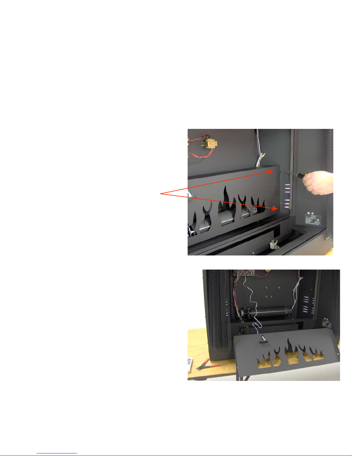
Removal of flame panel
• Use wire cutters to clip
the plastic wire tie
binding the remote
control receiver wire.
• Use a screwdriver to
remove the screws on
the right and left edges
of the flame cover panel.
• The panel may be placed
upon the floor in front of
the fireplace during
service
Page 12
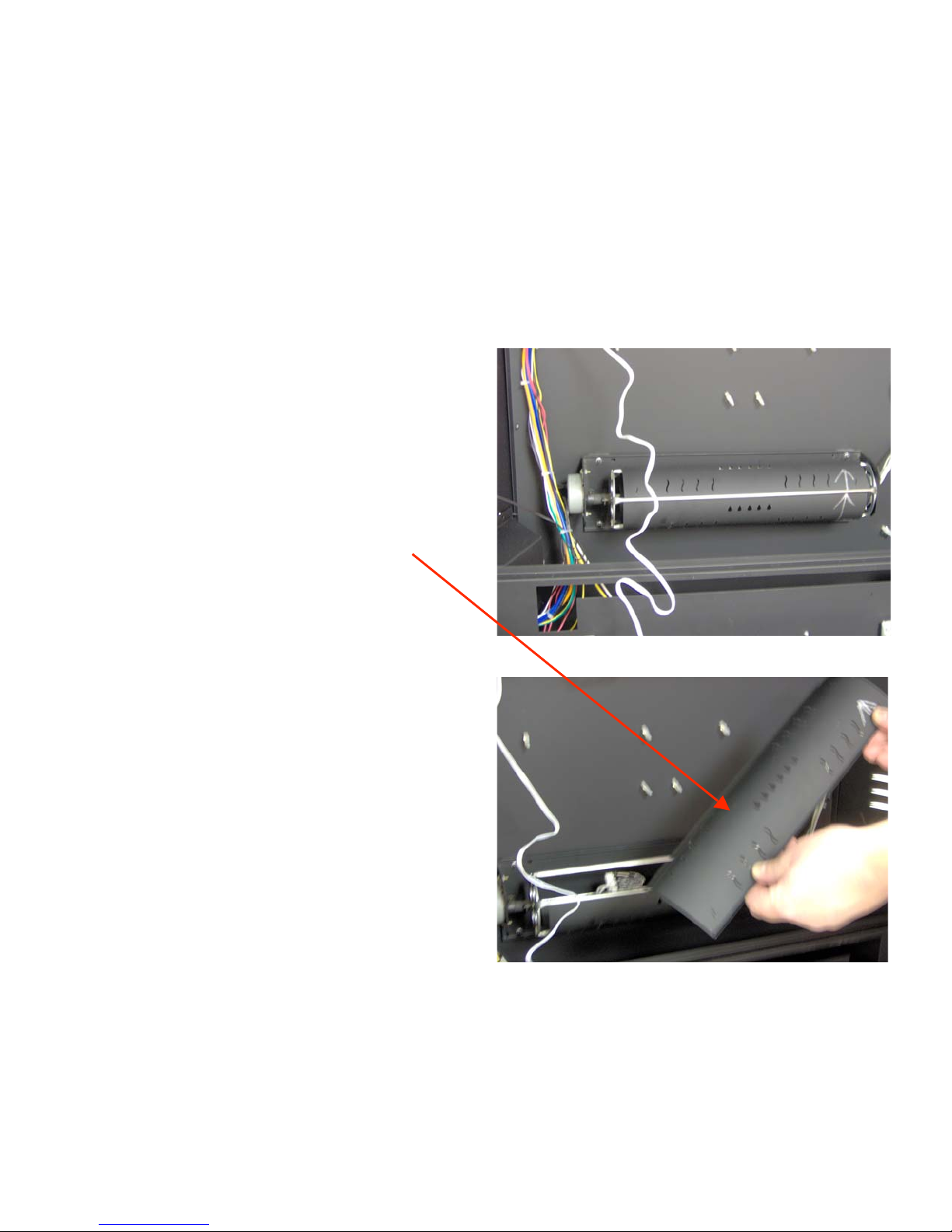
Changing bulbs in flame
cylinder
• Grasp the top of the
flame cylinder and
squeeze gently
disengaging the flame
cylinder cover.
• Lift the cover off to
expose the two flame
bulbs.
Caution: The edges of the flame
cylinder may be sharp! Wear
protective gloves to prevent
injury
Page 13
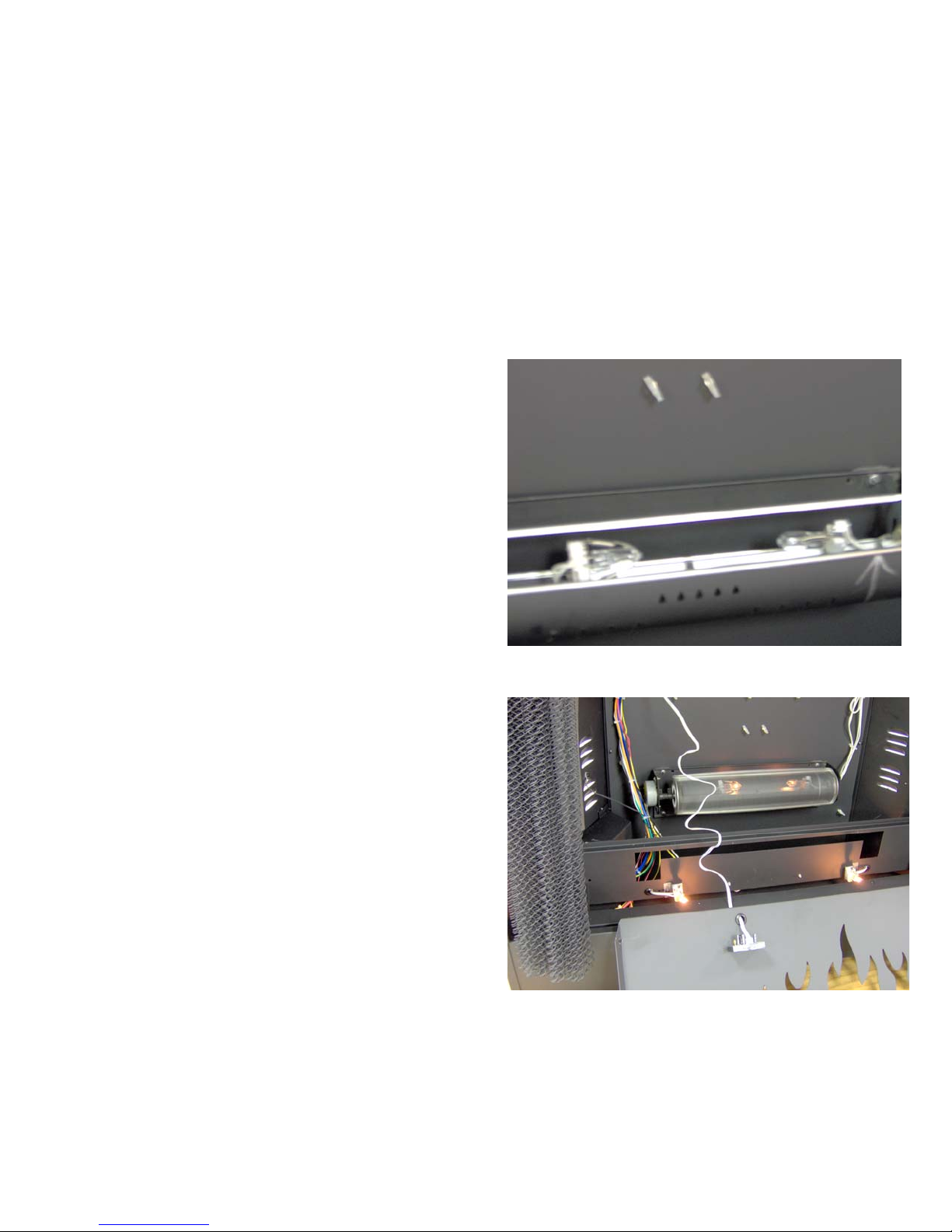
Lights: Flame and Ember
• With the flame cylinder
cover removed, the two
bulbs are visible.
• When the flame switch is
activated the bulbs
should light and the
flame wheel should turn.
• Use the remote control to
brighten and to dim the
flame bulbs and the
ember bed bulbs.
• When testing voltage to
the ember and flame
lights:
– If the lights are
activated by the control
panel switch voltage
will be approximately
114VAC
– If the lights are
activated by the remote
control the dimmer
function will vary the
voltage from
approximately 4 VAC
(low) to 114 VAC at the
high setting.
Page 14
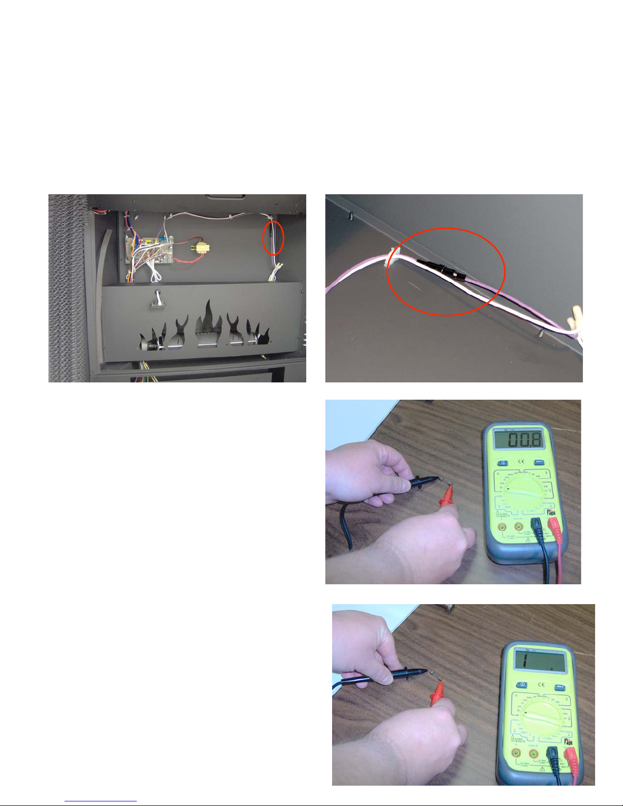
If ember and flame lights
fail to operate
•Check the in-line fuse located to the
right of the control board.
•Perform a continuity test on the fuse. If
the multimeter displays “1” the fuse has
blown and must be replaced.
•If the bulbs and fuse test “OK” , check
the continuity of the control panel switch
(power On/Off) and (lights On/Off)
•If switches test OK then test control
board.
•L- Light to N-Light =114VAC
•L-Flame to N-Flame = 114VAC
Page 15
Access to electrical
junction box
• Turn off power to the fireplace by
either unplugging the power cord or
setting the circuit breaker in the
home’s electrical panel to the “off”
position.
• Remove screws in junction box
cover.
Wire connections to a) factory supplied
power cord or b) Romex power
supply should be as follows:
120VAC linefireplace
black black
white blue N1
blue N2
white
green green/yellow
For 240 VAC wiring see page 42
Page 16

Wires for optional
controls
• The junction box
contains two wires that
may be used for an
optional wall switch to
control the flame
and/or an optional
thermostat to control
the heater.
• A length of black and
white wire is provided for
the connection of an
optional wall mounted
thermostat kit.
Page 17

Electrical junction box
• A length of red
wire may be
bundled in the
bottom of the
junction box.
• This allows
operation of the
fireplace from
an optional wall
mounted switch.
• See the
drawing for
proper wiring
• Note: to
operate the
fireplace from
the wall switch
the unit
mounted power
switch must be
in the ‘off’
position.
Page 18

Control board
• Replacement part # H1625
– Contains:
– Control Board
– Remote Receiver
Procedure for replacing control board:
• Disconnect Power Supply by
unplugging power cord or
turning off circuit breaker.
• Orient replacement board to match
defective board.
• Hold replacement board directly
below defective board.
• Remove one wire at a time from
the defective board and connect it
to the replacement board.
• Repeat until all wires have been
transferred.
• Use needle nose pliers to squeeze
the plastic corner fasteners to
release the defective board.
Remove defective board
• Place replacement board over
corner fasteners and push to lock
in place.
• Confirm all connections with the
wiring diagram.
• Restore power and test fireplace
functions.
Page 19

Control board wiring
120 VAC to transformer
Line voltage to
Heater Elements
Red
Control Panel Switch
Main Power on/off
(also to optional wall
switch)
Red/Red
Temperature
sensor-heater
Black/Black
24 VAC from
transformer to board
Flame/Ember on/off
switch
Red/Black
Page 20

Control Board Wiring (Hot)
L-FAN: Black wire
(hot) to fan motor
L-M: Brown wire
(hot) to flame motor
P-L: Black wire (hot) from junction box- to board- to
fusible link
L-Light: Yellow wire
(hot) to ember lights
L-R1 & L-R2: Red wires
(hot) to heater element
Black wire from board to
fusible link
L-Flame: Purple
wire(hot) to flame
wheel lights
Page 21

Control board wiring
(neutral)
L-N: Not used
N-Flame: White (neutral)
from flame wheel lights
N-M: White wire (neutral) from
flame wheel motor
N-Fan: White wire(neutral)
from fan motor
N-Power: White wire(neutral) from
junction box to control board
N-Light: white wire (neutral) from
ember lights
Page 22

Sensors/ Switches
Heater switch
black/yellow
Main power switch red/red
Transformer/
Temperature sensor
black/black
120 VAC to transformer
black/red
Wire for optional wall thermostat
black/white (stored in junction box)
Remote control sensor
white
Not used
Flame/Embers on-off switch
red/black
24 VAC from
transformer red/red
Page 23

Remote control sensor
Page 24

Page 25

Replacement of flame
cylinder motor
• Use wire cutter to
remove plastic wire ties
as shown
• Expose two crimp on
wire nuts (white to black)
and (brown to black)
leading to the motor
Page 26

Motor removal
• Cut crimped on wire nuts
to allow removal of the
motor,
• Use a small Phillips head
screw driver to loosen
the linkage clamp.
• Use needle-nose pliers
to loosen the nuts
securing the motor to its
mounting bracket
Page 27

Motor removal
• Remove the defective
motor.
Page 28

Replacement motor
• Slide the replacement
motor into the rubber
linkage and tighten.
• Reinstall motor mounting
screws and tighten the
two hex nuts
• With wire strippers strip
the ends of the
replacement motor wires
and also of the brown
and white wires as
shown.
• Using wire nuts secure
the connections. Use
wire ties to re-bundle the
wires. Tuck wires into
plastic retainers
Page 29

Control switches
• Top photo: Main power
switch (note 4 red wires
are connected to this
switch to allow for the
use of an optional wall
switch)
• Middle photo: Heater
switch (Black and yellow
wires)
• Lower photo: Flame
switch (Red and black
wires)
• Perform a continuity test
to confirm that switches
are functioning properly.
Disconnect one wire
from each switch before
conducting the test.
Page 30

Continuity test: control
panel switches
• Earlier production models of the
MPE-36R have switches that
were soldered to their wires
rather than the push on
connector that are used on later
models.
• To test these soldered switches:
– See page 21 of the manual for the
location of the switch connector at
the control board.
– Remove the connector from the
control board.
– Set your multimeter to Ohms and
conduct a continuity test of the
wires and sw itch.
– When the sw itch is “off”/open the
multimeter w ill display “1” .
– When the sw itch is “on”/closed the
multimeter should display a
measure of resistance (0.1
approx.)
• If the multimeter displays “1” with
the switch in the “on” setting, the
switch is defective and must be
replaced.
• If you suspect a defective
switch, test the switch 6 – 10
times to confirm proper
operation and reliability.
Page 31

Remote control does not
function
• Power switches must be correctly set to allow remote control
operation.
• When the switches are correctly set, a “beep” will be heard
whenever a button on the remote control is depressed.
• If no sound is heard test in this order:
– Check switch settings
– Check batteries in remote control
– Test operation with another remote control transmitter
– Test operation with a replacement remote receiver connected to the board
– Replace control board
Page 32

Heater sensor
• The heater sensor
measures the air
temperature and turns
the heater and blower on
and off based upon the
setting of the remote
control.
• If the heater does not
turn on, the remote may
have been set to a
temperature lower than
the current room
temperature.
• Set the remote to “high”
if the room temperature
is lower than 86 degrees,
the heater should turn on.
Page 33

Heater Access
• Remove screws to release heater panel
• Grasp handle and lower heater to the service position.
• The heater will be suspended by two wire cables
Page 34

Testing the heater
• Testing the fuse plate
assembly
• Unplug the fireplace or
turn off the power at the
circuit breaker.
• Remove one black wire
lead to the fuse plate
assembly as shown
• Perform a continuity test
with the multimeter set to
Ohms. (picture to the
right indicates a good
fuse plate assembly)
Page 35

Testing the heater
(continued)
• Continuity test Fuse
Plate Assembly
• Remove one black lead
as shown.
• Set multimeter to “Ohms”
to measure resistance.
• Touch probes to spade
connectors on fuse plate
assembly as shown.
• If multimeter displays “1”
the fuse plate assembly
has failed and must be
replaced.
• Failure of the fuse plate
assembly may indicate
incorrect wiring in the
junction box or of the
heater element, or the
possibility of a short
circuit .
• Check and confirm all
wiring before
reactivating power
supply.
Page 36

To replace “fuse plate
screw
assembly”
screw
• Disconnect wires as shown above.
• Remove screws from end of fuse plate assembly
• Replace with part # H5043
Page 37

Orange
Blue
Red
Heater element wiring
• Heating element wiring:
• Orange : Top center
terminal
• Blue wires N1 & N2:
Middle terminals
• Red wires (from control
board): lower terminals
Page 38

Blower wiring 120VAC
From Left:
Black
White
Orange
Blue
Blue
• Note: 120 VAC operation:
• Blue wires N1 & N2 run directly from electrical
junction box to the heater element.
• Orange wire (dummy wire in 120 VAC installation)
also runs directly from the electrical junction box to
the heater element. Orange wire must be capped in
the junction box.
• Black (hot) wire runs from junction box to the control
board and then to the fusible link for the heater
• White (neutral wire) runs from the junction box to the
control board,
Page 39

Blower wiring 240 volt
From left:
Black
White
Orange
Blue
Blue
• Note: 240 VAC operation:
• Blue wires N1 & N2 run directly from electrical junction box
to the heater element. (Blue wires are not used in 240VAC
and must not be connected to a power source in the
junction box. Blue wires should be capped with wire
nuts to prevent accidental contact with power supply)
• Orange (hot) wire also runs directly from the electrical
junction box to the heater element. Orange wire is connected
to Hot (Red or Black power supply in the junction box)
• Black (hot) wire runs from junction box to the control board
and then to the fuse plate assembly for the heater Black wire
is connect to Hot (Red or Black power supply in the junction
box)
• White (neutral wire) runs from the junction box to the control
board.
Page 40

Orange
Blue
Red
Heater element wiring
• To test the heater element:
• Turn off all power at the circuit breaker or unplug the power
cord (120VAC)
• Remove orange wire, both blue wires, and both red wires from
the heater element.
• With the multimeter set to Ohms: touch the probes to the
terminals from which the red wires were removed.
• If the multimeter displays “1” the heating element has failed and
must be replaced.
• Normal Ohm readings for the heater coil (red to red) is between
65 Ohms and 90 Ohms.
• Be careful to replace all wires as shown in this picture.
Page 41

Electrical grounding
• For safe operation the fireplace must be grounded.
• In electrical junction box the green ground wire from the power
supply must be firmly connected to the green and yellow wire
shown here. Confirm that the ground wire is properly and securely
fastened to the ground screw located to the left of the flame wheel
motor.
• Inspect the power cord to make certain that the ground plug is in
place and has not been removed.
• Using a multimeter confirm that the electrical outlet has proper
polarity and is properly grounded.
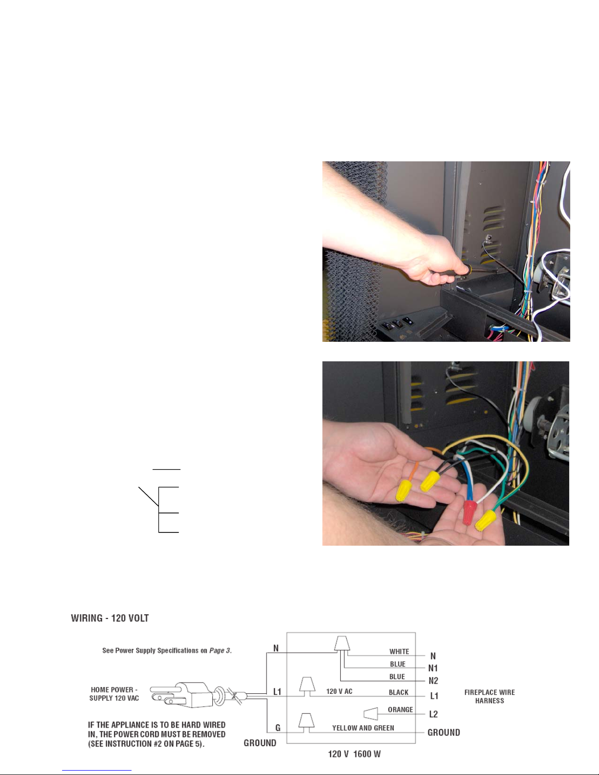
Page 42

Junction box wiring
Page 43

Wiring diagram 120 Volt
Page 44

Wiring diagram 240 Volt
Page 45

MPE-33R
Page 46

Page 47

MPE-36R
Page 48

 Loading...