

Page 1

OPERATION
E2005 Lennox Industries Inc.
Dallas, Texas, USA
RETAIN THESE INSTRUCTIONS
FOR FUTURE REFERENCE
51M37 Merit® Series Thermostat
The Lennox Merit® Series 5/2 day programmable
electronic thermostat 51M37 provides excellent
temperature control and a large, easy-to-read display. It
includes a programmable filter change reminder, an
equipment maintenance reminder, and a system check
indicator to notify the user when the equipment requires
service.
The 51M37 is suitable for heat pump, 3-stage heat/2-stage
cool applications using a gas or electric auxiliary heat
source. An optional outdoor temperature sensor provides
auxiliary heat lockout, balance point operation, and
dual−fuel compatibility.
MANUAL
®
51M37 Merit
5/2 Day Programmable Thermostat
CONTROLS
505,050M
05/05
Supersedes 03/05
Table of Contents
51M37 Series Thermostat 1. . . . . . . . . . . . . . . . . . . . . .
General 1. . . . . . . . . . . . . . . . . . . . . . . . . . . . . . . . . . . . . .
Introduction 1. . . . . . . . . . . . . . . . . . . . . . . . . . . . . . . . . . .
Initial Thermostat Power-up 1. . . . . . . . . . . . . . . . . . . . .
Buttons, Backlight, Timers & Settings 2. . . . . . . . . . . .
DAY/TIME − Set Day and Time 2. . . . . . . . . . . . . . . . . .
HEAT − Heat Mode 3. . . . . . . . . . . . . . . . . . . . . . . . . . . .
COOL − Cool Mode 4. . . . . . . . . . . . . . . . . . . . . . . . . . . .
HOLD − Temperature Hold Mode 5. . . . . . . . . . . . . . . .
PROG − Thermostat Programming 5. . . . . . . . . . . . . . .
FAN − Controlling Fan Operation 6. . . . . . . . . . . . . . . . .
SETTINGS − Filter and Maintenance Reminders 6. . .
SETTINGS − Balance Point 7. . . . . . . . . . . . . . . . . . . . .
Service Indicator 7. . . . . . . . . . . . . . . . . . . . . . . . . . . . . .
Thermostat RESET 7. . . . . . . . . . . . . . . . . . . . . . . . . . . .
Removing/Installing Thermostat 7. . . . . . . . . . . . . . . . .
Default Thermostat Settings 7. . . . . . . . . . . . . . . . . . . .
Technical Specifications 8. . . . . . . . . . . . . . . . . . . . . . . .
Thermostat Output Table 10. . . . . . . . . . . . . . . . . . . . . . .
Series
Litho U.S.A.
General
These instructions are intended as a general guide and do
not supersede local codes in any way. Consult authorities
having jurisdiction before installation.
Check equipment for shipping damage. If you find any
damage, immediately contact the last carrier.
Introduction
This document describes the operation of Lennox thermostat
51M37. Refer to the installation manual for instructions regarding installation and wiring of the thermostat.
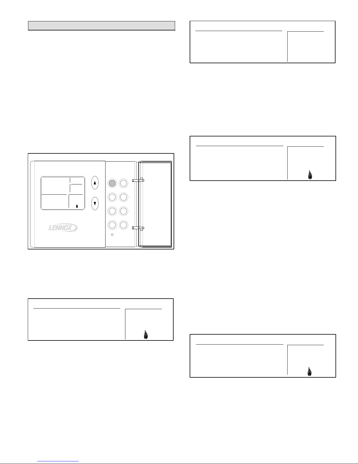
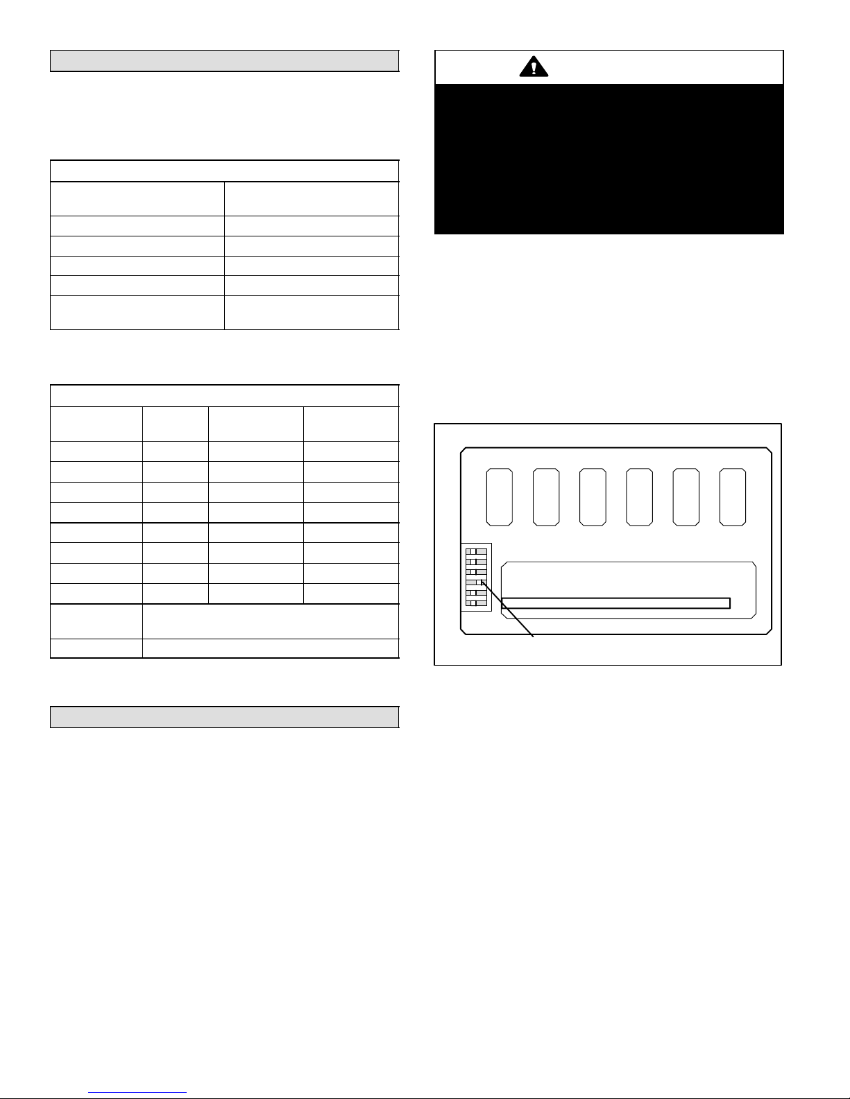
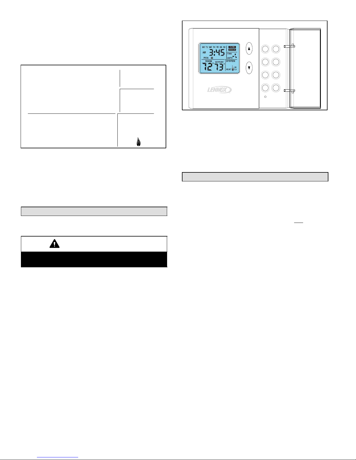
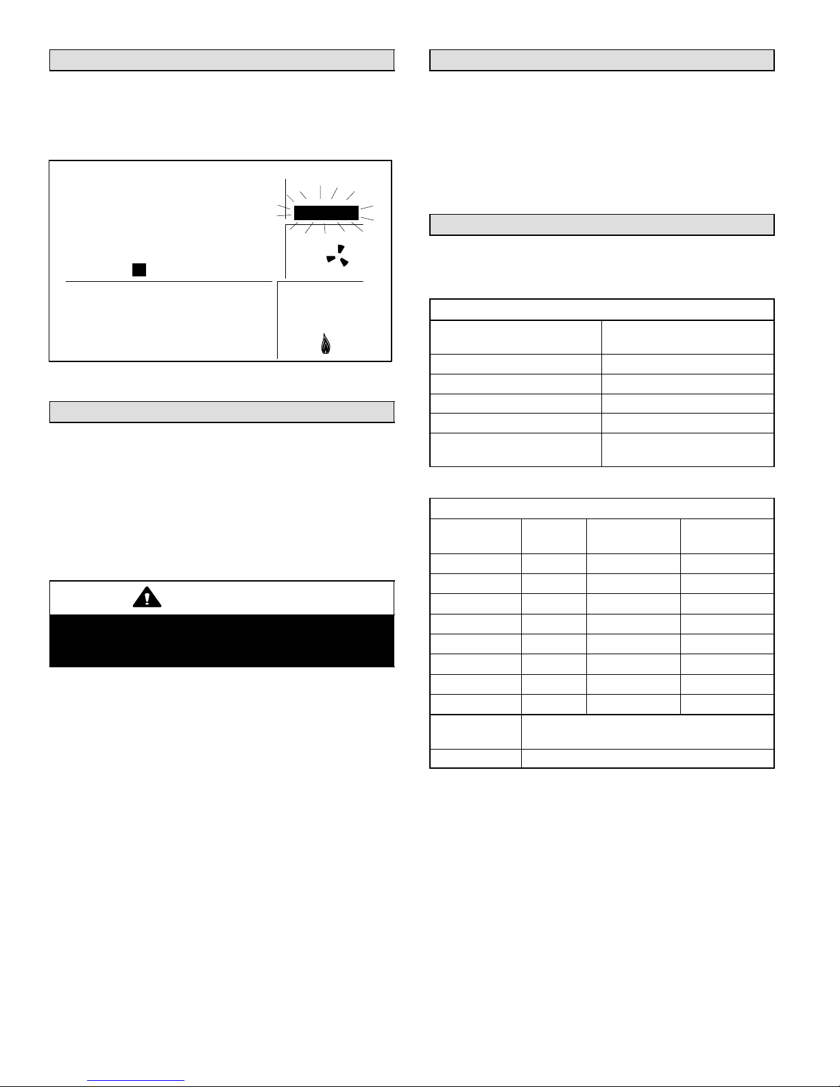
Initial Thermostat Power-up
When power is initially applied to the thermostat, the display will appear as shown in figure 1.
Initial Power−Up Display
MO TU WE TH FR SA SU
AM
I8:88
PM
PROG A | B | C | D HOLD
ROOM
SETPOINT
°
°
88
All display segments are momentarily activated. This occurs as a normal part of thermostat initialization.
88
Figure 1
MAINT
FILTER
SERVICE
FAN
ON
AUTO
SYSTEM
COOL
OFF
EMG.
HEAT
Hi
Lo
05/05 505,050M
*2P0505* *P505050M*
Page 1
Page 2

Within a few seconds, the Home Screen appears (see figure 2) with default settings as shown. After about 1 minute
of initialization time, the actual room temperature will be
displayed.
NOTE − Tables 2 and 3 on page 8 show all system and
programming defaults.
Home Screen
MO TU WE TH FR SA SU
MAINT
FILTER
SERVICE
AM
I2:00
PM
PROG A B C D HOLD
ROOM
°
70
FAN
ON
AUTO
SYSTEM
COOL
OFF
HEAT
Figure 2
At this point, the thermostat will be fully functional; its default temperature setpoint (not shown) is 70°F. At this
point, if the equipment has been fully powered and if a heat
demand were present, the system would begin operating.
NOTE − Temperature scale default is Fahrenheit units but
may be reset to show Celsius, if desired. See page 8.
Buttons, Backlight, Timers & Settings
Buttons are located behind the small door on the right−
hand side of the thermostat (see figure 3).
IMPORTANT
Do NOT begin pressing buttons until after you read
the following section describing each button.
A pale blue display backlight illuminates for 30 seconds
each time any button is pressed.
When PROG or DAY/TIME is pressed, a field begins flashing, expecting another input. Start making changes within
15 seconds or the HOME screen will return.
Thermostat Buttons
Heat
Cool
Prog
Day/Time
Fan
Hold
Settings
Enter
(DOOR
OPEN)
Figure 3
When an Arrow, HOLD, HEAT, or COOL button is pressed,
SETPOINT and the temperature setting appears for 15
seconds. If desired, start making changes within 15 seconds or the HOME screen will return. The backlight will
turn off 15 seconds after the HOME screen reappears.
DAY/TIME − Setting the Day and Time
Press the DAY/TIME button and set the CURRENT hour,
minute, and day of week as follows:
1. AM12" will flash on the screen. Press the Up/Down arrows buttons to change the hour. (AM" or PM" must
correspond to time of day.) Press DAY/TIME OR, if ad-
justing for daylight savings time, pressing ENTER
stores the single change and exits to the HOME
screen, bypassing minutes and day of week.
2. Minutes will flash. Use the Up/Down arrow buttons to
display the minutes past the hour. Press DAY/TIME.
3. Day MO" (Monday) will flash. Use Up/Down arrow
buttons to display the current day. Day selections are
abbreviated as MO, TU", WE", TH", FR", SA",
and SU". Press DAY/TIME.
4. The HOME screen reappears; confirm day and time
are correct. This completes day and time setting.
505050M 5/1/05
Page 2
Page 3
HEAT − Using the Heat Mode
Normal Heat Mode
In normal heat mode, both the heat pump and the backup
heat source are used to provide heat. If the thermostat detects that the heat pump is not able to provide enough heat
(as may be the case in very cold weather), then the backup
heat source is activated.
Emergency Heat Mode
In emergency heat mode, only the backup heat source
provides heat the heat pump is disabled. The backup
heat source is activated only when there is a heat demand.
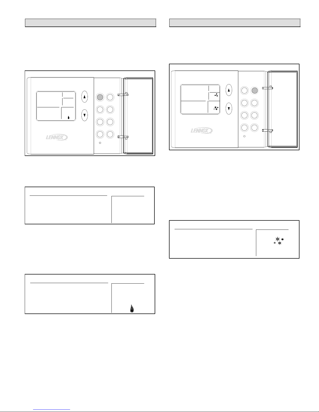
Enabling Normal Heat Mode
Use the HEAT button to select normal heat mode, emergency heat mode, or to disable heat modes as desired. If
the thermostat is in OFF or COOL mode, pressing the Heat
button enables Heat mode. This is indicated by HEAT in
the SYSTEM box as shown in figure 4.
Normal Heat Mode Enabled
Heat
Prog
Fan
Settings
Day/Time
°
Cool
Hold
Enter
SYSTEM
COOL
OFF
EMG.
HEAT
MO
AM
5:30
PM
ROOM
°
66
Enabling Emergency Heat Mode
If the thermostat is in heat mode, pressing the Heat button
enables EMG. HEAT mode (see figure 5). If the thermostat
is in normal heat mode when the HEAT button is pressed,
then emergency heat mode is enabled.
Emergency Heat Mode Enabled
ROOM
62
Disabling Heat Mode
If the thermostat is in emergency heat mode when the
HEAT button is pressed, then heat modes are disabled.
This is indicated by OFF in the SYSTEM box as shown in
figure 6.
HOLD
SETPOINT
70
°
FAN
AUTO
SYSTEM
HEAT
°
Figure 4
SETPOINT
75
Figure 5
Heat Mode Disabled
°
°
°
SYSTEM
COOL
OFF
HEAT
SYSTEM
COOL
OFF
HEAT
SYSTEM
COOL
OFF
Hi
HEAT
ROOM
75
Heating Demand
The thermostat must be in either normal or emergency
heat mode in order to properly control the heating equipment. In either heat mode, when the actual temperature is
lower than the temperature setpoint (as shown in figure 7),
the thermostat detects a heating demand and activates the
heating equipment to satisfy the demand. Heating operation is indicated by a flame icon in the SYSTEM box.
ROOM
72
When the actual temperature rises above the temperature
setpoint, the flame icon will disappear. This indicates that
the heating demand has been satisfied and that the heating equipment has been turned off.
Heat pump operation is locked out for 5 minutes after a demand has been satisfied. If another heat pump demand
occurs during this 5−minute interval, the flame icon will
flash; however, the heat pump will not run until the 5−minute delay has elapsed.
NOTE − The heat pump is activated for at least 4 minutes if
no buttons are pressed during the demand interval. The
backup heat source is activated for at least 3 minutes if no
buttons are pressed during the demand interval.
If your system supports 3−stage heating (as does the
51M37 thermostat), you may notice various heating levels
being delivered during a demand.
If a small heat pump heating demand is present, "Lo" is displayed in the SYSTEM box; if a large heat pump heating
demand is present, "Hi" is displayed (see figure 8).
Large Heat Demand
ROOM
SETPOINT
°
75
Figure 6
Heating Demand
SETPOINT
°
75
Figure 7
SETPOINT
°
65
75
Figure 8
Page 3
51M37 SERIES 5/2
Page 4

COOL − Using the Cool Mode
Enabling and Disabling Cool Mode
Use the COOL button to enable or disable cool mode as
desired. If the thermostat is in HEAT or OFF mode, cool
mode is enabled when the COOL button is pressed. This is
indicated by COOL in the SYSTEM box (see figure 9).
Cooling Demand
Set the thermostat to cool mode to control the cooling
equipment. Then, if the room temperature is higher than
the temperature setpoint, as shown in figure 11, the thermostat detects a cooling demand and will activate the cooling equipment to satisfy the demand.
Cooling Demand
MO TU WE TH FR SA SU
Turn Cool ON/OFF
Heat
Prog
Fan
Settings
Day/Time
°
Cool
Hold
Enter
SYSTEM
COOL
OFF
HEAT
MO
AM
PM
I0:30
ROOM
°
75
If the thermostat is in cool mode, pressing the Cool button
disables COOL mode (indicated by OFF in the SYSTEM
box − see figure 10).
ROOM
75
FAN
HOLD
AUTO
SYSTEM
COOL
SETPOINT
°
70
Figure 9
Cool Mode Disabled
SETPOINT
°
75
Figure 10
AM
i0:00
PM
PROG A B C D HOLD
ROOM
SETPOINT
°
75
Cooling operation is indicated by flashing snowflake"
icons in the SYSTEM box. When the actual temperature
drops below the temperature setpoint, the snowflake icons
will disappear. This indicates that the cooling demand has
been satisfied and that the cooling equipment has been
turned off.
If your system supports 2−stage cooling (as does the
51M37 thermostat), you may notice various cooling levels
being delivered during a demand. Also, if a small cooling
demand is present, "Lo" will be displayed in the SYSTEM
box. However, if a large cooling demand is present, "Hi" will
be displayed in the SYSTEM box (shown in figure 11).
NOTE − If no buttons are pressed during a demand for
cooling, the equipment must operate for at least 4 minutes.
After a demand has been satisfied, cooling equipment operation is locked out for 5 minutes. If another cooling demand occurs during this 5−minute interval, COOL" and the
snowflakes will flash; however, the cooling equipment will
not operate until the 5−minute delay has elapsed.
70
Figure 11
°
FAN
ON
AUTO
SYSTEM
COOL
OFF
Hi
HEAT
505050M 5/1/05
Page 4
Page 5
HOLD − Using Temperature Hold Modes
PROG − Thermostat Programming
When HOLD is displayed at the HOME screen, the thermostat is in a temperature hold condition. This means that
the temperature program data is ignored and the thermostat functions much like a non−programmable thermostat.
Adjusting Temperature Setpoint in Hold Mode
The temperature setpoint represents the desired temperature of the space around the thermostat. The default temperature setpoint in Hold mode is 70°F.
To adjust the setpoint, press the UP or DOWN (YB) arrow
buttons (see figure 12); the existing setpoint is displayed to
the right of the actual room temperature. Each button
press adjusts the setpoint up or down by 1 degree.
Hold Temperature Mode
MO
AM
PM
I0:36
ROOM
72
°
HOLD
SETPOINT
68
°
FAN
AUTO
SYSTEM
COOL
Heat
Prog
Fan
Settings
Cool
Day/Time
Hold
Enter
Figure 12
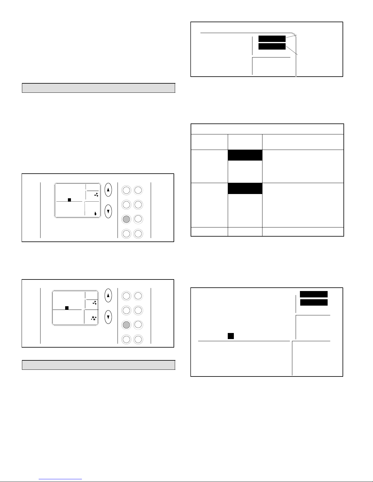
After the desired setpoint is reached, the HOME screen
will reappear after about 15 seconds.
Permanent Hold Mode
At any time the program is running, from the HOME
screen, set a permanent hold (program override) by pressing the HOLD button (see figure 12). The thermostat now
functions much like a non−programmable thermostat. Use
the Up/Down arrow buttons to adjust the hold setpoint. To
return to the program, press HOLD again.
Temporary (2-Hour) Hold
At any time the program is running, from the HOME
screen, set a temporary 2-hour hold by pressing the Up/
Down arrow buttons until the desired setpoint is displayed;
HOLD" flashes (see figure 13). This overrides the program for 2 hours from the last button press, then returns to
the program.
Temporary Hold Temperature Mode
MO
AM
PM
I0:36
PROG B HOLD
ROOM
°
72
SETPOINT
68
°
FAN
AUTO
SYSTEM
COOL
Heat
Prog
Fan
Settings
Cool
Day/Time
Hold
Enter
Figure 13
While in Temporary Hold, press HOLD once to switch to
Permanent Hold (HOLD displays solid; PROG not displayed); press HOLD again to return to the program
(PROG displays; HOLD not displayed).
The 51M37 thermostat can be programmed to perform a
set of either heating or cooling events (but not a
combination of heat and cool) for 5 consecutive days using
a set of 4 unique events per day. The remaining 2 days can
then be set for a different set of 4 unique events per day.
Both the consecutive days and the events/temperature are
set by the homeowner.
To Change Consecutive Days...
To alter the 5 consecutive days, press and hold the
PROG button for 5 seconds. The 5 consecutive day period
is then displayed (default is MOnday thru FRiday). To
change to a different 5-consecutive days, use the Up/
Down arrow buttons. Any 5 consecutive−day span may be
selected, for example, in figure 14, Saturday through
Wednesday is defined as the 5−day programming (Thursday and Friday would constitute the 2−day programming).
Press the PROG button when finished.
Change Consecutive days
MO TU WE TH FR SA SU
Figure 14
To Set Program Events and Temperatures...
Figure 15 gives an example of how the two sets of programs can be set for a normal workweek and weekend.
In the 5−day bar graph, note how programs A and C reflect
the desired warmth while the home IS occupied (72°); B
allows less heating while the home is NOT occupied; D reflects a cooler sleeping temperature. The 2−day bar graph
would support day−long occupancy and, because the first
program begins later, a less−demanding time schedule.
5/2 Program Example
5−DAY PROGRAM:
2−DAY PROGRAM:
|A | B | C | D |
72°
68°
64°
6AM NOON 6PM MID 6AM
|A| B | C | D |
72°
68°
64°
6AM NOON 6PM MID 6AM
NIGHT
NIGHT
Figure 15
NOTE − Pressing ENTER during the following programming steps, saves and exits to the HOME screen.
To program events and temperatures, perform the following steps, once with Cool selected and once with Heat selected.
1. Press and release PROG. AM 6:00", period A", and
the 5 consecutive days are displayed; AM 6" flashes.
2. Use the Up/Down arrow buttons to select the desired
hour; press PROG when the desired hour is reached.
3. Use the Up/Down arrow buttons to select the desired
minute; press PROG.
4. Use the Up/Down arrow buttons to select the desired
temperature setpoint; press PROG.
Page 5
FILTER
51M37 SERIES 5/2
Page 6
5. Repeat steps 2 through 4 for periods B, C, and D.
(1st
)
(Off, 1, 3, 6, 12); f
(2nd
)
(Off, 6, 12). U
thi
6. Repeat steps 1 through 5 for the 2−day program.
NOTE − This thermostat will NOT automatically switch
from heating to cooling, or vice versa; operator involvement is required. At the change of seasons, or to accomodate abnormal seasonal temperature swings, you must
manually select to the opposite conditioning (Heat or Cool)
program.
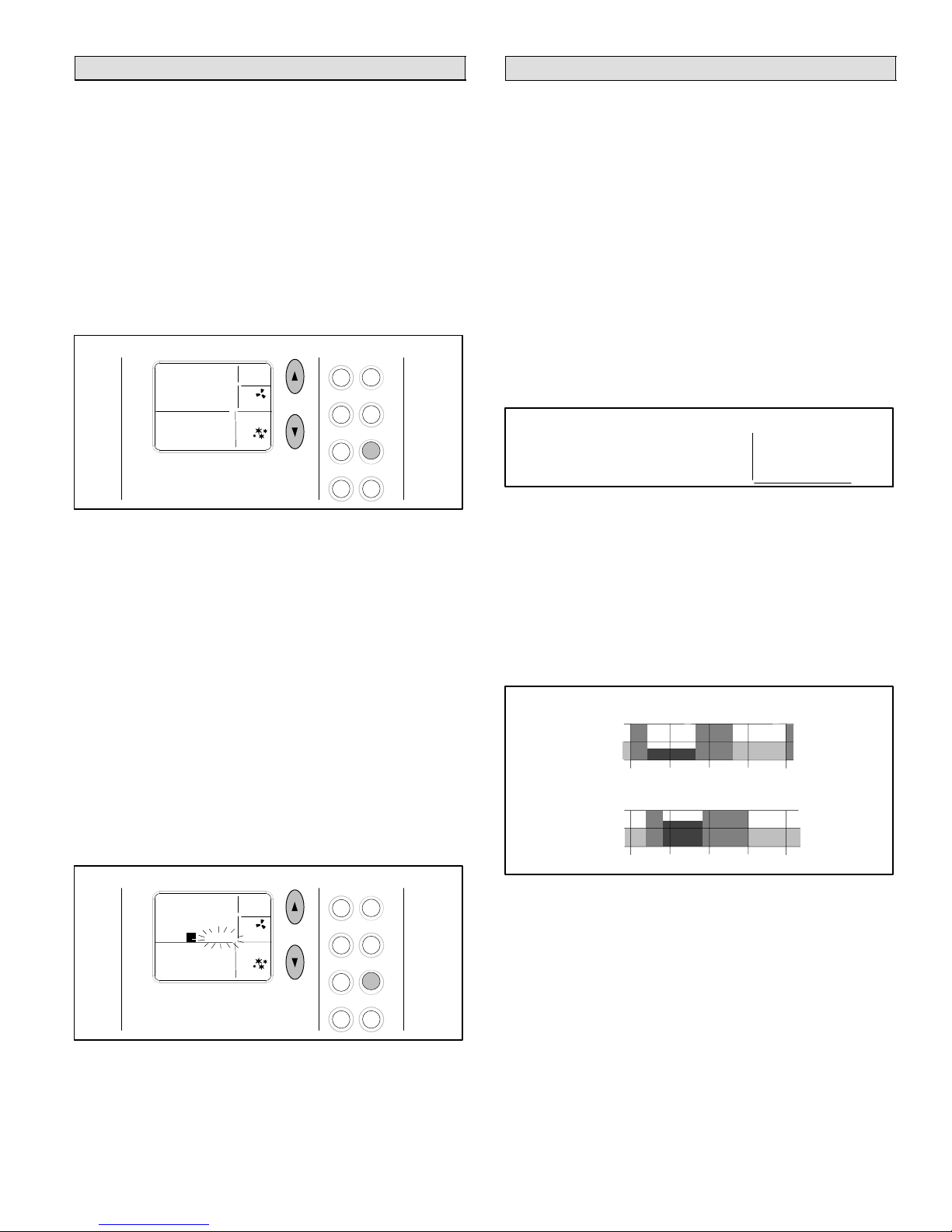
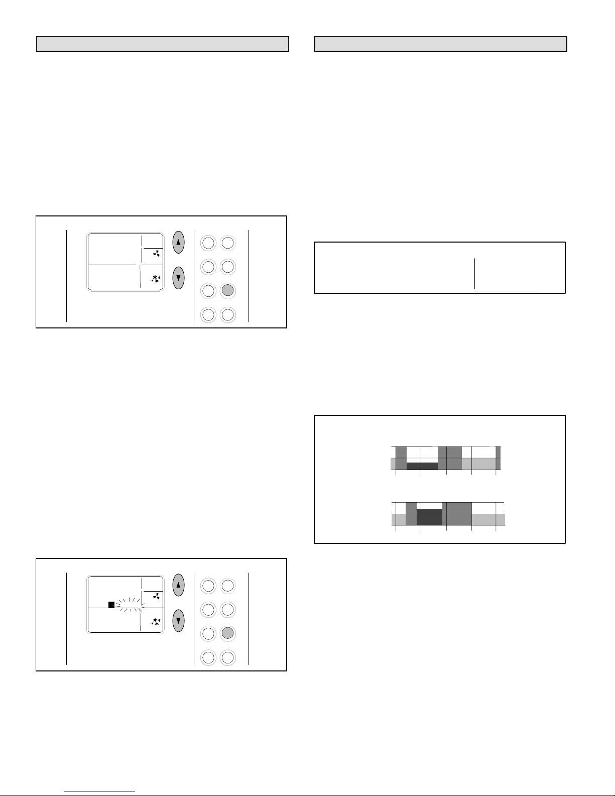
FAN − Controlling the Fan Operation
Use the FAN button to select either continuous fan mode or
auto fan mode.
To change from continuous to auto fan mode (or vice versa), press the FAN button. Note whether a fan icon in the
FAN box is present (indicating that the fan is running) or not
(fan not running).
If continuous fan mode is enabled (ON displayed in FAN
box − see figure 16), the fan will run continuously regardless of whether the heating or cooling equipment is running.
MO
AM
PM
PROG B
ROOM
67
Using Fan ON
FAN
I0:I0
°
ON
SYSTEM
HEAT
Heat
Prog
Fan
Settings
Cool
Day/Time
Hold
Enter
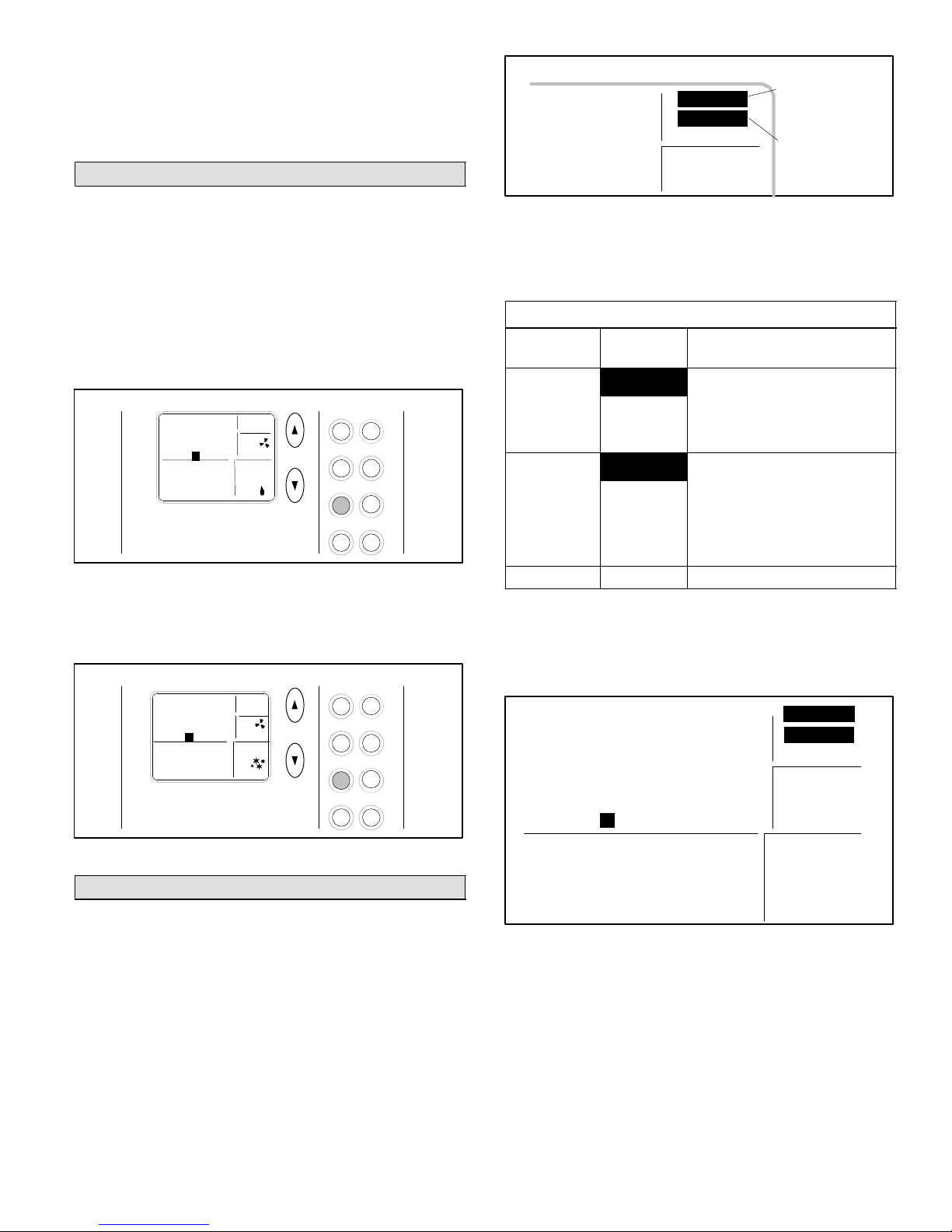
Reminder Settings Display
MAINT
FILTER
OFF
For MAINT,
press Settings
button 2 times
For FILTER,
press Settings
button 1 time
Figure 18
The default setting for the reminders is OFF (disabled).
Press Up/Down arrow buttons to select the desired reminder intervals.
Table 1
Filter and Maintenance Reminders
Buttons to
Use
Settings
press
then Arrows
to scroll
selections
Settings
press
then Arrows
to scroll
selections
Enter Stores settings.
Reminder
FILTER
MAINT
Available Settings and
How to Use
Total fan run time expressed in
months
example, if fan runs 12 hours a
day, 1 month reminder displays
in 2 calendar months.
Elapsed chronological time in
months
for example, to remind yourself
when to perform routine checks
or when to call a technician for
perodic preventive
maintenance.
se
or
s,
Figure 16
If auto fan mode is selected (AUTO displayed in FAN box −
see figure 17), the fan will only run when the heating or
cooling equipment is running.
MO
AM
PM
I0:36
PROG B
ROOM
72
Using Fan Auto
FAN
AUTO
SYSTEM
COOL
°
Heat
Prog
Fan
Settings
Cool
Day/Time
Hold
Enter
Figure 17
SETTINGS − Filter/Maintenance Reminders
The 51M37 thermostat is designed to remind you when the
filter needs changing or when routine maintenance is required, as (and if) defined, by you. These optional reminders are not enabled until you activate them. To do so, press
the Settings button (shown below the Fan button in figure
17) once or twice for the desired reminder as shown in figure 18 and as described in table 1.
NOTE − The HOME screen will reappear about 15 seconds
after the final arrow button press. OR, press ENTER at any
time to store any changes and exit to the HOME screen.
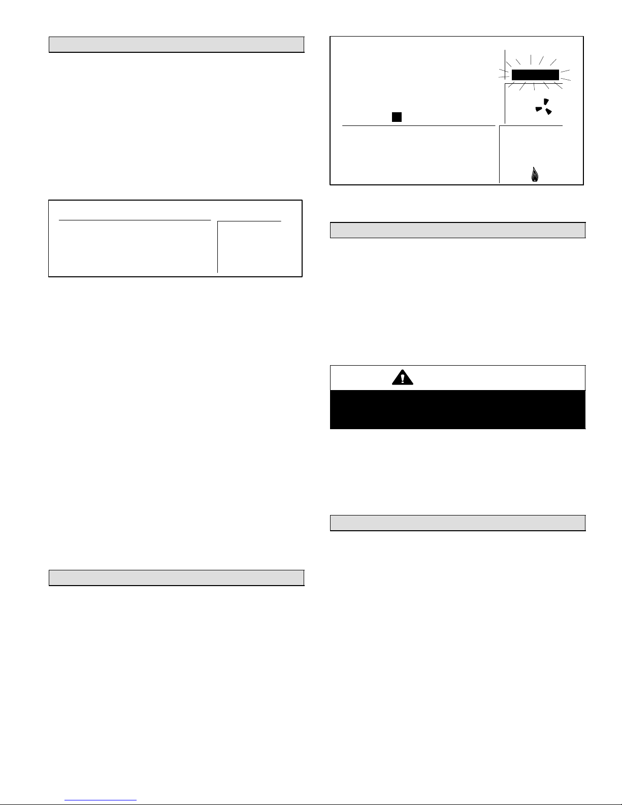
After either programmed interval has elapsed, the reminder will be displayed as shown in figure 19.
Reminders
MO TU WE TH FR SA SU
AM
PM
I0:i2
PROG A B C D HOLD
ROOM
°
78
MAINT
FILTER
SERVICE
FAN
ON
AUTO
SYSTEM
COOL
OFF
HEAT
Figure 19
After the filter has been changed or maintenance performed, reset the reminder by pressing the SETTINGS
button for 4 seconds. The screen will blink for a few moments to indicate that the timer has been reset.
505050M 5/1/05
Page 6
Page 7
SETTINGS − Balance Point
NOTE − The balance point is only available with the outdoor sensor.
If the optional outdoor sensor (X2658) is connected to the
thermostat, balance point adjustment is available. The balance point feature allows the measured outdoor temperature to govern operation of the heat pump and backup heat
source.
Use the SETTINGS button to access the balance point
setting. If the outdoor sensor is attached to the thermostat,
press the SETTINGS button three times to access the Balance Point Settings screen (see figure 20).
Balance Point Setting
Service Indicator Flashing
MO TU WE TH FR SA SU
AM
I0:i4
PM
PROG A B C D HOLD
ROOM
°
79
Figure 21
FILTER
SERVICE
FAN
ON
AUTO
SYSTEM
COOL
OFF
HEAT
ROOM
SETPOINT
°
6p
The balance point can be set at any temperature between
1°F and 55°F (−17°C to 13°C). A balance point setting of
zero disables the balance point function (in this case, the
thermostat behaves as if no outdoor sensor is attached).
The default balance point setting is 55°F.
To adjust the balance point up or down, press the Up/Down
arrow buttons to the right of the display screen. The balance point setting increases by 1°F each time the Up button is pressed and decreases by 1°F each time the Down
button is pressed.
After the desired balance point is reached, the HOME
screen will reappear after about 15 seconds.
NOTE − The balance point feature allows the outdoor temperature to rise or fall 3°F above or below the balance
point. This prevents excessive cycling of the equipment
when the outdoor temperature is near the balance point.
For example, if the balance point is 40°F and the actual
outdoor temperature is 35°F, the outdoor temperature
must rise to 43°F before equipment adjustment occurs.
Conversely, if the balance point is 40°F and the actual outdoor temperature is 45°F, the outdoor temperature must
drop to 37°F before equipment adjustment occurs.
Service Indicator
When abnormal equipment operation is detected, the
SERVICE indicator will flash on the screen (see figure 21).
This indicates that the equipment requires service from a
qualified service technician.
55
Figure 20
Thermostat RESET
Under some abnormal conditions, it may be necessary to
reset" the thermostat to its default condition. Such a RESET would delete all programming and settings and therefore should only be used on rare occasions when the the
thermostat fails to function as designd and/or as programmed. Such an instance can occur as a result of a power surge or similar electrical disturbance (e.g. after an electrical storm or power outage). The RESET button can be
used to recover from this situation.
CAUTION
When the RESET button is pressed, ALL settings revert back to the defaults, including the default program (see tables 2 and 3).
The RESET button is an unlabeled, recessed button located behind the door, on the right−hand side of the thermostat, below the SETTINGS button (see figure 3). Use a
paper clip or small pencil to press the RESET button; ALL
thermostat settings will be reset to the defaults listed in the
Default Thermostat Settings section.
Removing/Installing Thermostat
The thermostat hinges on tabs on the top of the subbase;
no tool is needed to remove the thermostat from the subbase. Pivot the bottom of the thermostat outward (releasing the snaps), then lift up to remove.
To replace it, first position the top tilted toward the wall
bracket and align it until you feel the tabs and slots engage;
then, while the top is in place, pivot the bottom toward the
wall until the thermostat snaps into place.
Page 7
51M37 SERIES 5/2
Page 8
Default Thermostat Settings
CAUTION
Default thermostat settings are shown in table 2 and the
default program is shown in table 3.
Table 2
Default Thermostat Settings
Mode Heat (Permanent Hold
Mode)
Setpoint 70°F (or 21°C)
Fan Auto
Filter Reminder OFF
Maintenance Reminder OFF
Equipment Protection
Reset Back to Zero
Timers
Table 3
Default Program Settings
Temperature
Programs Time
(Heat)
Weekday − A 6:00am 70_F / 21°C 78_F / 26°C
Weekday − B 8:00am 62_F / 17°C 85_F / 29°C
Weekday − C 6:00pm 70_F / 21°C 78_F / 26°C
Weekday − D 10:00pm 62_F / 17°C 82_F / 28°C
Weekend − A 6:00am 70_F / 21°C 78_F / 26°C
Weekend − B 8:00am 62_F / 17°C 85_F / 29°C
Weekend − C 6:00pm 70_F / 21°C 78_F / 26°C
Weekend − D 10:00pm 62_F / 17°C 82_F / 28°C
Weekday Monday, Tuesday, Wednesday,
Thursday, Friday
Weekend Saturday, Sunday
Temperature
(Cool)
24VAC is present on the terminals of the thermostat
bracket. If removing the thermostat from the wall,
use caution and avoid touching any of the connector terminals on the wall bracket.
Also, when working with the thermostat dip
switches, use a non−conductive tool and take caution to avoid making any contact with the circuit
board, its imprinted circuitry and its connector
prongs.
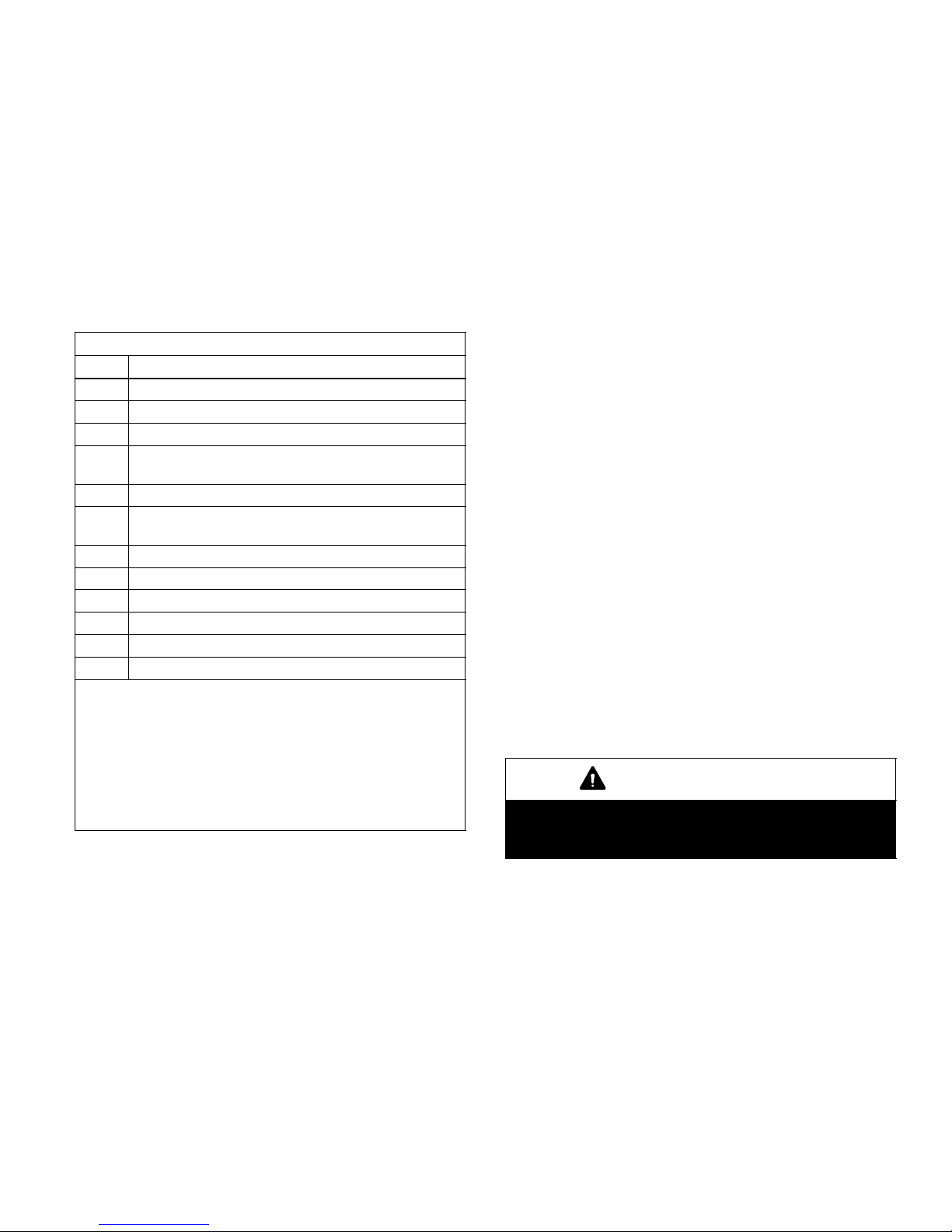
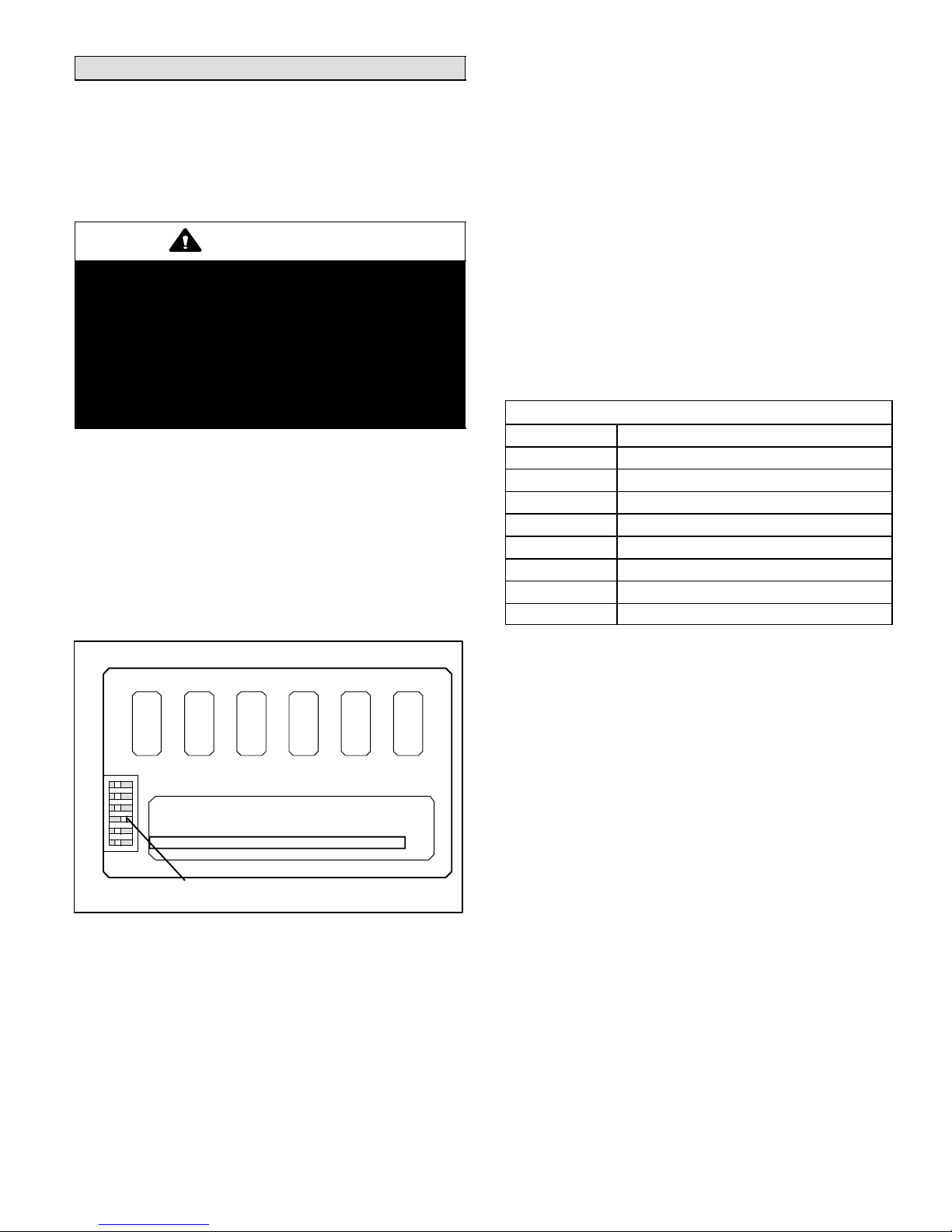
Temperature Display
Display Scale: Fahrenheit or Celsius user selectable (via
DIP switch; see figure 22)
Display range: 35°F (2°C) to 99°F (37°C)
Display resolution: 1°F (1°C)
Display Accuracy: +/−1°F
If the Fahrenheit/Celsius display must be changed, use a
plastic, non−conductive tool to push the dip switch to the
right position (see figure 22).
Changing Fahrenheit/Celsius Setting
1
2
3
4
5
6
PLUG IN (Use Care To Avoid Bending Prongs.)
F/C (Fahrenheit/Celsius) switch
shown in Celsius position
Figure 22
Technical Specifications
Thermostat Type
Electronic programmable thermostat for heat pump,
3-stage heat/2-stage cool.
NOTE − 2 stages of heat pump heat and one stage of auxiliary (gas or electric) backup heat are supported.
Power Supply Range
18VAC − 30VAC (24VAC nominal), 60Hz
505050M 5/1/05
Temperature Measurement Range
Measurement Scale: Fahrenheit
Measurement Range: 35°F to 99°F
Measurement Resolution: 0.5°F
Measurement Accuracy: +/−1°F
Field Offset: via DIP switches to +/−3°F
Sampling Method: temperature measurements sampled
every 15 seconds. Displayed temperature is the average
of the last four measurements.
Temperature Setpoint Range
Setting range: 50°F (10°C) to 90°F (32°C)
Setting resolution: 1°F (1°C)
Page 8
Page 9
Smart Setback Recovery (via DIP switch #6)
Smart Setback Recovery (SSR) affects the way the thermostat responds to program events. If SSR is disabled, the
thermostat will react to a program event at the time the
event occurs. However, if SSR is enabled, the thermostat
will react to a program event before the event occurs such
that the desired temperature is reached at the time of the
event, not after.
Fan Control
AUTO or ON modes.
I/O Relays
All thermostat relays are latching type to minimize power
consumption.
Table 4
51M37 Terminal Designations
Term. Description
B Reversing valve, heat active
O Reversing valve, cool active
R 24VAC
Y1 First-stage cooling/heating, compressor
energized
W1* Auxiliary heating, furnace energized
Y2 Second-stage cooling/heating, compressor
energized
E* Emergency heat
G Fan control
L Service Indicator
C 24VAC common
T Outdoor temperature sensor connection 1
T Outdoor temperature sensor connection 2
* For most applications, E will be jumpered to W1. If separate wires are not provided for both E and W1, jumper
the E terminal to the W1 terminal on the thermostat subbase. For applications involving the use of a balance
point (whereby the outdoor temperature is to be used to
restrict either heat pump operation or backup heat
source operation), the optional outdoor sensor (part
number X2658) MUST be installed.
Equipment Protection Timers
Minimum Compressor OFF time: 5 minutes
Minimum Compressor ON time: 4 minutes
Minimum Furnace ON time: 3 minutes
Minimum furnace cycle time (elapsed time between any
furnace activation and the next furnace activation): 6 minutes.
Minimum elapsed time between any compressor activation and the next compressor activation: 6 minutes.
NOTE − All protection timers (except the compressor OFF
timer) can be over−ridden if a heating or cooling demand is
initiated or terminated using the UP, DOWN, HEAT, or
COOL buttons.
Equipment Protection Override
Both the minimum compressor OFF timer and the minimum equipment cycle timer can be over−ridden by pressing and holding either the HEAT or COOL button down for 4
seconds.
Over−Temperature Protection
Thermal-mechanical switch opens W1, Y1, Y2, and E at
93°F+/−6°F.
Filter Reminder
Settings of Off, 1, 3, 6 or 12 (months of fan run time) are
available. When programmed time has elapsed, a FILTER
indicator is displayed.
Maintenance Reminder
Settings of Off, 6 or 12 (months of chronological time) are
available. When programmed time has elapsed, a maintenance indicator MAINT" is displayed.
Service Reminder
The SERVICE indicator is displayed only under the following conditions:
S if the thermostat Y1 terminal has been activated with
24VAC for at least 5 minutes, AND the L terminal is
shorted to the R terminal;
OR
S if the thermostat Y1 terminal has been activated with
24VAC for at least 5 minutes, AND the L terminal is
shorted to the C terminal.
Power Loss/Recovery
Thermostat memory is retained for a minimum of 24 hours
during a power loss (includes retention of program information, HOLD status, programmed temperature setpoint,
heat/cool and fan mode settings, filter reminder status,
maintenance reminder status, and equipment protection
timers). After 24 hours of power loss, programmed settings
will be lost and replaced with default settings.
IMPORTANT
Power must be applied for at least six consecutive
hours prior to a power loss in order for memory to
be retained for the specified time.
LCD Backlight
Activated for 30 seconds when any button is pressed.
NOTE − During an electrical storm or similar disturbance,
the backlight may activate for a few seconds. This is normal and will no longer occur after the electrical disturbance
has passed.
Thermostat Operating Conditions
35°F to 105°F, 5% to 90% RH
Thermostat Storage Conditions
−40°F to 185°F, 5% to 95% RH
Page 9
51M37 SERIES 5/2
Page 10
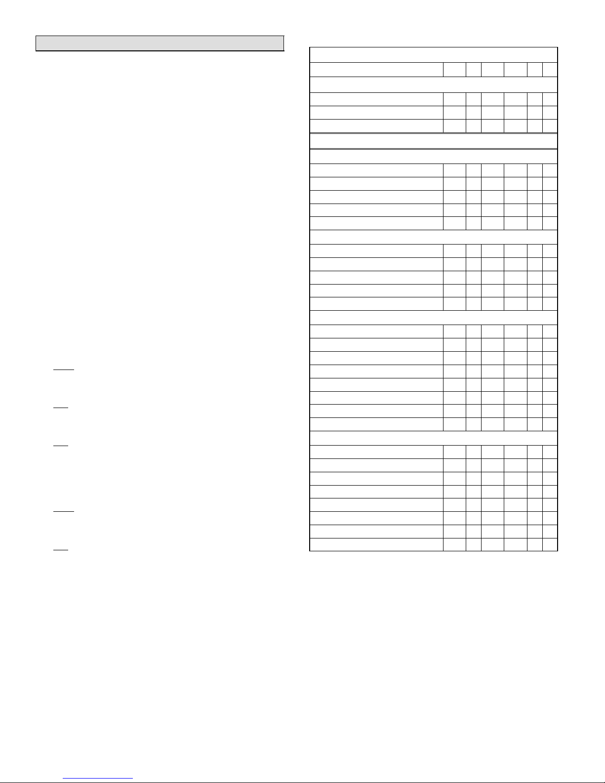
Thermostat Output Table
Table 5 depicts the 51M37 thermostat output states for various input conditions. The following notes described terms
used in the table.
NOTES:
S X = output is activated with 24VAC.
S BBP: outdoor temperature is below balance point
S ABP: outdoor temperature is above balance point
S In all cases, the state of the B terminal is opposite that
of the O terminal
S Data are tabulated for AUTO fan setting. If the fan set-
ting is ON, the G output is activated in all cases
S Upstage timers:
30 minutes (when upstaging from small to large
demand)
15 minutes (HEAT MODE ONLY − when upstaging
from large to very large demand)
S The temperature ranges expressed in the following
definitions of SMALL/LARGE/VERY LARGE" demands are for guidance only; actual temperatures
may vary:
With a small HEAT demand, temperature is:
below setpoint –0.5F but above setpoint –1.5F
AND 30-minute upstage timer HAS NOT expired.
With a large HEAT demand, temperature is:
less than setpoint –1.5F
OR 30-minute upstage timer HAS expired.
With a very large heat demand, temperature is:
below setpoint –2.5F
OR 15−minute 2nd upstage timer HAS expired.
Emergency heat demand (only if emergency heat is
enabled): temperature is below setpoint –0.5F.
With a small COOL demand, temperature is:
above setpoint +0.5F but below setpoint +1.5F
AND 30-minute upstage timer HAS NOT expired.
With a large COOL demand, temperature is:
above setpoint +1.5F
OR 30-minute upstage timer HAS expired.
Table 5
THERMOSTAT OUTPUTS
Demand Condition
W1 E Y1 Y2 G O
Cooling Demands
SMALL X X X
LARGE X X X X
No Demand X
Heating Demands
w/Electric Backup (no outdoor sensor)
SMALL X X
LARGE X X X
Very LARGE X X X X
Emergency X X
No Demand
w/Gas Backup (dual fuel; no outdoor sensor)
SMALL X X
LARGE X X X
Very LARGE X
Emergency X
No Demand
w/Electric Backup (outdoor sensor attached)
SMALL (Above Balance Point) X X
LARGE (ABP) X X X
Very LARGE (ABP) X X X
SMALL (Below Balance Point) X X
LARGE (BBP) X X X
Very LARGE (BBP) X X X X
Emergency X X
No Demand
w/Gas Backup (dual fuel; outdoor sensor attached)
SMALL (ABP) X X
LARGE (ABP) X X X
Very LARGE (ABP) X
SMALL (BBP) X
LARGE (BBP) X
Very LARGE (BBP) X
Emergency X
No Demand
505050M 5/1/05
Page 10
Page 11
OPERATION
E2005 Lennox Industries Inc.
Dallas, Texas, USA
RETAIN THESE INSTRUCTIONS
FOR FUTURE REFERENCE
51M35 Merit® Series Thermostat
The Lennox Merit® Series 5/2 day programmable
electronic thermostat 51M35 provides excellent
temperature control and a large, easy-to-read display. This
product includes a programmable filter change reminder,
an equipment maintenance reminder, and a system check
indicator to notify the user when the equipment requires
service.
Thermostat 51M35 is suitable for non-heat pump, twostage heat/two-stage cool applications using a gas or electric furnace.
MANUAL
®
51M35 Merit
5/2 Day Programmable Thermostat
CONTROLS
505,049M
05/05
Supersedes 03/05
Table of Contents
51M35 Series Thermostat 1. . . . . . . . . . . . . . . . . . . . . .
General 1. . . . . . . . . . . . . . . . . . . . . . . . . . . . . . . . . . . . . .
Introduction 1. . . . . . . . . . . . . . . . . . . . . . . . . . . . . . . . . . .
Initial Thermostat Power-up 1. . . . . . . . . . . . . . . . . . . . .
Buttons, Backlight, Timers & Settings 2. . . . . . . . . . . .
DAY/TIME − Set Day and Time 2. . . . . . . . . . . . . . . . . .
HEAT − Heat Mode 3. . . . . . . . . . . . . . . . . . . . . . . . . . . .
COOL − Cool Mode 3. . . . . . . . . . . . . . . . . . . . . . . . . . . .
HOLD − Temperature Hold Mode 4. . . . . . . . . . . . . . . .
PROG − Thermostat Programming 4. . . . . . . . . . . . . . .
FAN − Controlling Fan Operation 5. . . . . . . . . . . . . . . . .
SETTINGS − Filter /Maintenance Reminder 5. . . . . . .
Service Indicator 6. . . . . . . . . . . . . . . . . . . . . . . . . . . . . .
Thermostat RESET 6. . . . . . . . . . . . . . . . . . . . . . . . . . . .
Removing/Installing Thermostat 6. . . . . . . . . . . . . . . . .
Default Thermostat Settings 6. . . . . . . . . . . . . . . . . . . .
Technical Specifications 7. . . . . . . . . . . . . . . . . . . . . . . .
Thermostat Output Table 8. . . . . . . . . . . . . . . . . . . . . . .
Series
Litho U.S.A.
General
These instructions are intended as a general guide and do
not supersede local codes in any way. Consult authorities
having jurisdiction before installation.
Check equipment for shipping damage. If you find any
damage, immediately contact the last carrier.
Introduction
This document describes the operation of Lennox thermostat
51M35. Refer to the installation manual for instructions regarding installation and wiring of the thermostat.
Initial Thermostat Power-up
When power is initially applied to the thermostat, the display will appear as shown in figure 1.
Initial Power−Up Display
MO TU WE TH FR SA SU
AM
I8:88
PM
PROG A | B | C | D HOLD
ROOM
SETPOINT
°
°
88
All display segments are momentarily activated. This occurs as a normal part of thermostat initialization.
88
Figure 1
MAINT
FILTER
SERVICE
FAN
ON
AUTO
SYSTEM
COOL
OFF
EMG.
HEAT
Hi
Lo
05/05 505,049M
*2P0505* *P505049M*
Page 1
Page 12
Within a few seconds, the Home Screen appears (see figure 2) with default settings as shown. After about 1 minute
of initialization time, the actual room temperature will be
displayed.
NOTE − Tables 2 and 3 on page 6 show all system and
programming defaults.
MO TU WE TH FR SA SU
Home Screen
MAINT
FILTER
SERVICE
AM
I2:00
PM
PROG A B C D HOLD
ROOM
°
70
FAN
ON
AUTO
SYSTEM
COOL
OFF
HEAT
Figure 2
At this point, the thermostat will be fully functional; its default temperature setpoint (not shown) is 70°F. At this
point, if the equipment has been fully powered and if a heat
demand were present, the system would begin operating.
NOTE − Temperature scale default is Fahrenheit units but
may be reset to show Celsius, if desired. See page 7.
Buttons, Backlight, Timers & Settings
Buttons are located behind the small door on the right−
hand side of the thermostat (see figure 3).
IMPORTANT
Do NOT begin pressing buttons until after you read
the following section describing each button.
A pale blue display backlight illuminates for 30 seconds
each time any button is pressed.
When PROG or DAY/TIME is pressed, a field begins flashing, expecting another input. Start making changes within
15 seconds or the HOME screen will return.
Thermostat Buttons
Heat
Cool
Prog
Day/Time
Fan
Hold
Settings
Enter
(DOOR
OPEN)
Figure 3
When an Arrow, HOLD, HEAT, or COOL button is pressed,
SETPOINT and the temperature setting appears for 15
seconds. If desired, start making changes within 15 seconds or the HOME screen will return. The backlight will
turn off 15 seconds after the HOME screen reappears.
DAY/TIME − Setting the Day and Time
Press the DAY/TIME button and set the CURRENT hour,
minute, and day of week as follows:
1. AM12" will flash on the screen. Press the UP/DOWN
arrows to change the hour. (AM" or PM" must correspond to time of day.) Press DAY/TIME OR, if adjust-
ing for daylight savings time, pressing ENTER stores
the single change and exits to the HOME screen, bypassing minutes and day of week.
2. Minutes will flash. Use the UP/DOWN arrow button to
display the minutes past the hour. Press DAY/TIME.
3. Day MO" (Monday) will flash. Use UP or DOWN arrow
buttons to display the current day. Day selections are
abbreviated as MO, TU", WE", TH", FR", SA",
and SU". Press DAY/TIME.
4. The HOME screen reappears; confirm day and time
are correct. This completes day and time setting.
505049M 5/1/05
Page 2
Page 13
HEAT − Using the Heat Mode
COOL − Using the Cool Mode
Enabling and Disabling Heat Mode
The thermostat must be in the HEAT mode to control the
heating equipment. Press the Heat button to enable or disable HEAT mode. If the thermostat is in COOL or OFF
mode, pressing the Heat button enables the HEAT mode
(indicated by HEAT in the SYSTEM box − see figure 4).
Turn Heat ON/OFF
Heat
Prog
Fan
Settings
Cool
Day/Time
Hold
Enter
MO
AM
PM
ROOM
66
5:30
HOLD
SETPOINT
°
70
°
FAN
AUTO
SYSTEM
HEAT
Figure 4
If the thermostat is in heat mode, pressing the Heat button
disables HEAT mode (indicated by OFF in the SYSTEM
box − see figure 5).
Heat/Cool Mode Disabled
°
SYSTEM
COOL
OFF
HEAT
ROOM
75
°
SETPOINT
75
Figure 5
Heating Demand
Set the thermostat to heat mode to control the heating
equipment. Then, if the room temperature is lower than the
temperature setpoint, as shown in figure 6, the thermostat
detects a heating demand and will activate the heating
equipment to satisfy the demand.
Heating Demand
°
SYSTEM
COOL
OFF
HEAT
ROOM
72
°
SETPOINT
75
Figure 6
Heating operation is indicated by a flame icon in the SYSTEM box. When the actual temperature rises above the
temperature setpoint, the flame icon will disappear. This
indicates that the heating demand has been satisfied and
that the heating equipment has been turned off.
If your system supports 2−stage heating (as does the
51M35 thermostat), you may notice various heating levels
being delivered during a demand.
NOTE − Heating equipment is activated for at least 3 minutes if no buttons are pressed during the demand interval.
Enabling and Disabling Cool Mode
Use the COOL button to enable or disable cool mode as
desired. If the thermostat is in HEAT or OFF mode, cool
mode is enabled when the COOL button is pressed. This is
indicated by COOL in the SYSTEM box (see figure 8).
Turn Cool ON/OFF
Heat
Prog
Fan
Settings
Cool
Day/Time
Hold
Enter
MO
AM
PM
I0:30
ROOM
75
SETPOINT
°
70
HOLD
°
FAN
AUTO
SYSTEM
COOL
Figure 7
If the thermostat is in cool mode, pressing the Cool button
disables COOL mode (indicated by OFF in the SYSTEM
box − see figure 5).
Cooling Demand
Set the thermostat to cool mode to control the cooling
equipment. Then, if the room temperature is higher than
the temperature setpoint, as shown in figure 8, the thermostat detects a cooling demand and will activate the cooling
equipment to satisfy the demand.
Cooling Demand
°
SYSTEM
COOL
OFF
HEAT
ROOM
75
SETPOINT
°
70
Figure 8
Cooling operation is indicated by flashing snowflake"
icons in the SYSTEM box. When the actual temperature
drops below the temperature setpoint, the snowflake icons
will disappear. This indicates that the cooling demand has
been satisfied and that the cooling equipment has been
turned off.
If your system supports 2−stage cooling (as does the
51M35 thermostat), you may notice various cooling levels
being delivered during a demand. Also, if a small cooling
demand is present, "Lo" will be displayed in the SYSTEM
box. However, if a large cooling demand is present, "Hi" will
be displayed in the SYSTEM box (shown in figure 8).
NOTE − If no buttons are pressed during a demand for
cooling, the equipment must operate for at least 4 minutes.
After a demand has been satisfied, cooling equipment operation is locked out for 5 minutes. If another cooling demand occurs during this 5−minute interval, COOL" and the
snowflakes will flash; however, the cooling equipment will
not operate until the 5−minute delay has elapsed.
Page 3
Hi
51M35 SERIES 5/2
Page 14
HOLD − Using Temperature Hold Modes
PROG − Thermostat Programming
When HOLD is displayed at the HOME screen, the thermostat is in a temperature hold condition. This means that
the temperature program data is ignored and the thermostat functions much like a non−programmable thermostat.
Adjusting Temperature Setpoint in Hold Mode
The temperature setpoint represents the desired temperature of the space around the thermostat. The default temperature setpoint in Hold mode is 70°F.
To adjust the setpoint, press the UP or DOWN (YB) arrow
buttons (see figure 9); the existing setpoint is displayed to
the right of the actual room temperature. Each button
press adjusts the setpoint up or down by 1 degree.
Hold Temperature Mode
MO
AM
PM
I0:36
ROOM
72
°
HOLD
SETPOINT
68
°
FAN
AUTO
SYSTEM
COOL
Heat
Prog
Fan
Settings
Cool
Day/Time
Hold
Enter
Figure 9
After the desired setpoint is reached, the HOME screen
will reappear after about 15 seconds.
Permanent Hold Mode
At any time the program is running, from the HOME
screen, set a permanent hold (program override) by pressing the HOLD button (see figure 9). The thermostat now
functions much like a non−programmable thermostat. Use
the Up/Down arrow buttons to adjust the hold setpoint. To
return to the program, press HOLD again.
Temporary (2-Hour) Hold
At any time the program is running, from the HOME
screen, set a temporary 2-hour hold by pressing the Up/
Down arrow buttons until the desired setpoint is displayed;
HOLD" flashes (see figure 10). This overrides the program for 2 hours from the last button press, then returns to
the program.
Temporary Hold Temperature Mode
MO
AM
PM
I0:36
PROG B HOLD
ROOM
°
72
SETPOINT
68
°
FAN
AUTO
SYSTEM
COOL
Heat
Prog
Fan
Settings
Cool
Day/Time
Hold
Enter
Figure 10
While in Temporary Hold, press HOLD once to switch to
Permanent Hold (HOLD displays solid; PROG not displayed); press HOLD again to return to the program
(PROG displays; HOLD not displayed).
The 51M35 thermostat can be programmed to perform a
set of either heating or cooling events (but not a
combination of heat and cool) for 5 consecutive days using
a set of 4 unique events per day. The remaining 2 days can
then be set for a different set of 4 unique events per day.
Both the consecutive days and the events/temperature are
set by the homeowner.
To Change Consecutive Days...
To alter the 5 consecutive days, press and hold the PROG
button for 5 seconds. The existing 5 consecutive day period is then displayed (default is MOnday thru FRiday). To
change to a different 5-consecutive days, use the Up/
Down arrow buttons. Any 5 consecutive−day span may be
selected, for example, in figure 11, Saturday through
Wednesday is defined as the 5−day programming (Thursday and Friday would constitute the 2−day programming).
Press the PROG button when finished.
Change Consecutive days
MO TU WE TH FR SA SU
FILTER
Figure 11
To Set Program Events and Temperatures...
Figure 12 gives an example of how the two sets of programs can be set for a normal workweek and weekend.
In the 5−day bar graph, note how programs A and C reflect
the desired warmth while the home IS occupied (72°); B
allows less heating while the home is NOT occupied; D reflects a cool sleeping temperature. The 2−day bar graph
would support day−long occupancy and, because the first
program begins later, a less−demanding time schedule.
5/2 Program Example
5−DAY PROGRAM:
2−DAY PROGRAM:
|A | B | C | D |
72°
68°
64°
6AM NOON 6PM MID 6AM
|A| B | C | D |
72°
68°
64°
6AM NOON 6PM MID 6AM
NIGHT
NIGHT
Figure 12
NOTE − Pressing ENTER during the following programming steps, saves and exits to the HOME screen.
To program events and temperatures, perform the following steps, once with Cool selected and once with Heat selected.
1. Press and release PROG. AM 6:00", period A", and
the 5 consecutive days are displayed; AM 6" flashes.
2. Use the Up/Down arrow buttons to select the desired
hour; press PROG when the desired hour is reached.
3. Use the Up/Down arrow buttons to select the desired
minute; press PROG.
4. Use the Up/Down arrow buttons to select the desired
temperature setpoint; press PROG.
5. Repeat steps 2 through 4 for periods B, C, and D.
6. Repeat steps 1 through 5 for the 2−day program.
505049M 5/1/05
Page 4
Page 15
NOTE − This thermostat will NOT automatically switch
(1st
)
(Off, 1, 3, 6, 12); f
(2nd
)
(Off, 6, 12). U
thi
from heating to cooling, or vice versa; operator involvement is required. At the change of seasons, or to accomodate abnormal seasonal temperature swings, you must
manually select to the opposite conditioning (Heat or Cool)
program.
FAN − Controlling the Fan Operation
Reminder Settings Display
OFF
MAINT
FILTER
For MAINT,
press Settings
button 2 times
For FILTER,
press Settings
button 1 time
Use the FAN button to select either continuous fan mode or
auto fan mode.
To change from continuous to auto fan mode (or vice versa), press the FAN button. Note whether a fan icon in the
FAN box is present (indicating that the fan is running) or not
(fan not running).
If continuous fan mode is enabled (ON displayed in FAN
box − see figure 13), the fan will run continuously regardless of whether the heating or cooling equipment is running.
MO
AM
PM
PROG B
ROOM
67
Using Fan ON
FAN
I0:I0
°
ON
SYSTEM
HEAT
Heat
Prog
Fan
Settings
Cool
Day/Time
Hold
Enter
Figure 13
If auto fan mode is selected (AUTO displayed in FAN box −
see figure 14), the fan will only run when the heating or
cooling equipment is running.
MO
AM
PM
I0:36
PROG B
ROOM
72
Using Fan Auto
FAN
AUTO
SYSTEM
COOL
°
Heat
Prog
Fan
Settings
Cool
Day/Time
Hold
Enter
Figure 14
SETTINGS − Filter/Maintenance Reminders
The 51M35 thermostat is designed to remind you when the
filter needs changing or when routine maintenance is required, as (and if) defined, by you. These optional reminders are not enabled until you activate them. To do so, press
the Settings button (shown below the Fan button in figure
14) once or twice for the desired reminder as shown in figure 15 and as described in table 1.
Figure 15
The default setting for the reminders is OFF (disabled).
Press Up/Down arrow buttons to select the desired reminder intervals.
Table 1
Filter and Maintenance Reminders
Buttons to
Use
Settings
press
then Arrows
to scroll
selections
Settings
press
then Arrows
to scroll
selections
Enter Stores settings.
Reminder
FILTER
MAINT
NOTE − The HOME screen will reappear about 15 seconds
after the final arrow button press. OR, press ENTER at any
time to store any changes and exit to the HOME screen.
After either programmed interval has elapsed, the reminder will be displayed as shown in figure 16.
MO TU WE TH FR SA SU
AM
PM
I0:i2
PROG A B C D HOLD
ROOM
°
78
Available Settings and
How to Use
Total fan run time expressed in
months
example, if fan runs 12 hours a
day, 1 month reminder displays
in 2 calendar months.
Elapsed chronological time in
months
for example, to remind yourself
when to perform routine checks
or when to call a technician for
perodic preventive
maintenance.
Reminders
MAINT
FILTER
SERVICE
FAN
ON
AUTO
SYSTEM
COOL
OFF
HEAT
se
or
s,
Figure 16
After the filter has been changed or maintenance performed, reset the reminder by pressing the SETTINGS
button for 4 seconds. The screen will blink for a few moments to indicate that the timer has been reset.
Page 5
51M35 SERIES 5/2
Page 16
Service Indicator
Removing and Installing Thermostat
When abnormal equipment operation is detected, the
SERVICE indicator will flash on the screen (see figure 17).
This indicates that the equipment requires service from a
qualified service technician.
Service Indicator Flashing
MO TU WE TH FR SA SU
AM
I0:i4
PM
PROG A B C D HOLD
ROOM
°
79
Figure 17
FILTER
SERVICE
FAN
ON
AUTO
SYSTEM
COOL
OFF
HEAT
Thermostat RESET
Under some abnormal conditions, it may be necessary to
reset" the thermostat to its default condition. Such a RESET would delete all programming and settings and therefore should only be used on rare occasions when the the
thermostat fails to function as designd and/or as programmed. Such an instance can occur as a result of a power surge or similar electrical disturbance (e.g. after an electrical storm or power outage). The RESET button can be
used to recover from this situation.
CAUTION
When the RESET button is pressed, ALL settings revert back to the defaults, including the default program (see tables 2 and 3).
The RESET button is an unlabeled, recessed button located behind the door on the right−hand side of the thermostat, below the SETTINGS button (see figure 3). Use a paper clip or small pencil to press the RESET button; ALL
thermostat settings will be reset to the defaults listed in the
Default Thermostat Settings section.
The thermostat hinges on tabs on the top of the subbase;
no tool is needed to remove the thermostat from the subbase. Pivot the bottom of the thermostat outward (releasing the snaps), then lift up to remove.
To install it, first position the top tilted toward the wall bracket and align it until you feel the tabs and slots engage; then,
while the top is in place, pivot the bottom toward the wall
until the thermostat snaps into place.
Default Thermostat Settings
Default thermostat settings are in table 2 and the default
program is shown in table 3.
Table 2
Default Thermostat Settings
Mode Heat (Permanent Hold
Mode)
Setpoint 70°F (or 21°C)
Fan Auto
Filter Reminder OFF
Maintenance Reminder OFF
Equipment Protection
Timers
Default Program Settings
Programs Time
Weekday − A 6:00am 70_F / 21°C 78_F / 26°C
Weekday − B 8:00am 62_F / 17°C 85_F / 29°C
Weekday − C 6:00pm 70_F / 21°C 78_F / 26°C
Weekday − D 10:00pm 62_F / 17°C 82_F / 28°C
Weekend − A 6:00am 70_F / 21°C 78_F / 26°C
Weekend − B 8:00am 62_F / 17°C 85_F / 29°C
Weekend − C 6:00pm 70_F / 21°C 78_F / 26°C
Weekend − D 10:00pm 62_F / 17°C 82_F / 28°C
Weekday Monday, Tuesday, Wednesday,
Thursday, Friday
Weekend Saturday, Sunday
Reset Back to Zero
Table 3
Temperature
(Heat)
Temperature
(Cool)
505049M 5/1/05
Page 6
Page 17
Technical Specifications
Thermostat Type
Electronic programmable thermostat for 2−Stage (gas or
electric) Heat/2-Stage Cool, non−heat pump, non−power
robbing applications.
Power Supply Range
18VAC − 30VAC (24VAC nominal), 60Hz
CAUTION
24VAC is present on the terminals of the thermostat
bracket. If removing the thermostat from the wall,
use caution and avoid touching any of the connector terminals on the wall bracket.
Also, when working with the thermostat dip
switches, use a non−conductive tool and take caution to avoid making any contact with the circuit
board, its imprinted circuitry and its connector
prongs.
Temperature Display
Display Scale: Fahrenheit or Celsius user selectable (via
DIP switch; see figure 18)
Display range: 35°F (2°C) to 99°F (37°C)
Display resolution: 1°F (1°C)
Display Accuracy: +/−1°F
If the Fahrenheit/Celsius display must be changed, use a
plastic, non−conductive tool to push the dip switch to the
right position (see figure 18).
Temperature Setpoint Range
Setting range: 50°F (10°C) to 90°F (32°C)
Setting resolution: 1°F (1°C)
Smart Setback Recovery (via DIP switch #6)
Smart Setback Recovery (SSR) affects the way the thermostat responds to program events. If SSR is disabled, the
thermostat will react to a program event at the time the
event occurs. However, if SSR is enabled, the thermostat
will react to a program event before the event occurs such
that the desired temperature is reached at the time of the
event, not after.
Fan Control
AUTO or ON modes, gas or electric heat compatible via
DIP switches (also see Thermostat Output section).
I/O Relays
All thermostat relays are latching type to minimize power
consumption.
Table 4
51M35 Terminal Designations
Terminal Description
R 24VAC
Y1 First-stage cooling
W1 First-stage heating
Y2 Second-stage cooling
W2 Second-stage heating
G Fan control
L Service Indicator
C 24VAC common
Changing Fahrenheit/Celsius Setting
1
2
3
4
5
6
PLUG IN (Use Care To Avoid Bending Prongs.)
F/C (Fahrenheit/Celsius) switch
shown in Celsius position
Figure 18
Temperature Measurement Range
Measurement Scale: Fahrenheit
Measurement Range: 35°F to 99°F
Measurement Resolution: 0.5°F
Measurement Accuracy: +/−1°F
Field Offset: via DIP switches to +/−3°F
Sampling Method: temperature measurements sampled
every 15 seconds. Displayed temperature is the average
of the last four measurements.
Equipment Protection Timers
Minimum Compressor OFF time: 5 minutes
Minimum Compressor ON time: 4 minutes
Minimum Furnace ON time: 3 minutes
Minimum furnace cycle time (elapsed time between any
furnace activation and the next furnace activation): 6 minutes.
Minimum elapsed time between any compressor activation and the next compressor activation: 6 minutes.
NOTE − All protection timers (except the compressor OFF
timer) can be over−ridden if a heating or cooling demand is
initiated or terminated using the UP, DOWN, HEAT, or
COOL buttons.
Equipment Protection Override
Both the minimum compressor OFF timer and the minimum equipment cycle timer can be over−ridden by pressing and holding either the HEAT or COOL button down for 4
seconds.
Over−Temperature Protection
Thermal-mechanical switch opens W1 and W2 at
93°F+/−6°F.
Filter Reminder
Settings of Off, 1, 3, 6 or 12 (months of fan run time) are
available. When programmed time has elapsed, a FILTER
indicator is displayed.
Page 7
51M35 SERIES 5/2
Page 18

Maintenance Reminder
Settings of Off, 6 or 12 (months of chronological time) are
available. When programmed time has elapsed, a maintenance indicator MAINT" is displayed.
Service Reminder
The SERVICE indicator is displayed only under the following conditions:
S if the thermostat Y1 terminal has been activated with
24VAC for at least 5 minutes, AND the L terminal is
shorted to the R terminal;
OR
S if the thermostat Y1 terminal has been activated with
24VAC for at least 5 minutes, AND the L terminal is
shorted to the C terminal.
Power Loss/Recovery
Thermostat memory is retained for a minimum of 24 hours
during a power loss (includes retention of program information, HOLD status, programmed temperature setpoint,
heat/cool and fan mode settings, filter reminder status,
maintenance reminder status, and equipment protection
timers). After 24 hours of power loss, programmed settings
will be lost and replaced with default settings.
IMPORTANT
Power must be applied for at least six consecutive
hours prior to a power loss in order for memory to
be retained for the specified time.
LCD Backlight
Activated for 30 seconds when any button is pressed.
NOTE − During an electrical storm or similar disturbance,
the backlight may activate for a few seconds. This is normal and will no longer occur after the electrical disturbance
has passed.
Thermostat Operating Conditions
35°F to 105°F, 5% to 90% RH
Thermostat Storage Conditions
−40°F to 185°F, 5% to 95% RH
Thermostat Output Table
Table 5 depicts the 51M35 thermostat output states for various input conditions. The following notes described terms
used in the table.
NOTE − X = output is activated with 24VAC.
NOTE − The temperature ranges expressed in the following definitions of SMALL/LARGE" demands are for guidance only; actual temperatures may vary.
With a small HEAT demand, temperature is:
below setpoint –0.5F but above setpoint –1.5F
AND 30-minute upstage timer HAS NOT expired.
With a large HEAT demand, temperature is:
less than setpoint –1.5F
OR 30-minute upstage timer HAS expired.
With a small COOL demand, temperature is:
above setpoint +0.5F but below setpoint +1.5F
AND 30-minute upstage timer HAS NOT expired.
With a large COOL demand, temperature is:
above setpoint +1.5F
OR 30-minute upstage timer HAS expired.
Table 5
Thermostat Outputs
Condition W1 W2 Y1 Y2 G
Gas Heat, Auto Fan
HEAT Demand, SMALL X
HEAT Demand, LARGE X X
COOL Demand, SMALL X X
COOL Demand, LARGE X X X
No Demand
Gas Heat, Continuous Fan
HEAT Demand, SMALL X X
HEAT Demand, LARGE X X X
COOL Demand, SMALL X X
COOL Demand, LARGE X X X
No Demand X
Electric Heat, Auto Fan
HEAT Demand, SMALL X X
HEAT Demand, LARGE X X X
COOL Demand, SMALL X X
COOL Demand, LARGE X X X
No Demand
Electric Heat, Continuous Fan
HEAT Demand, SMALL X X
HEAT Demand, LARGE X X X
COOL Demand, SMALL X X
COOL Demand, LARGE X X X
No Demand X
505049M 5/1/05
Page 8
Page 19

OPERATION
E2005 Lennox Industries Inc.
Dallas, Texas, USA
RETAIN THESE INSTRUCTIONS
FOR FUTURE REFERENCE
51M34 Merit® Series Thermostat
The Lennox Merit® Series 5/2 day programmable
electronic thermostat 51M34 provides excellent
temperature control and a large, easy-to-read display. This
product includes a programmable filter change reminder,
an equipment maintenance reminder, and a system check
indicator to notify the user when the equipment requires
service.
Thermostat 51M34 is suitable for non−heat pump, singlestage heat/single-stage cool applications with either gas or
electric furnace.
MANUAL
®
51M34 Merit
5/2 Day Programmable Thermostat
CONTROLS
505,048M
05/05
Supersedes 03/05
Table of Contents
51M34 Series Thermostat 1. . . . . . . . . . . . . . . . . . . . . .
General 1. . . . . . . . . . . . . . . . . . . . . . . . . . . . . . . . . . . . . .
Introduction 1. . . . . . . . . . . . . . . . . . . . . . . . . . . . . . . . . . .
Initial Thermostat Power-up 1. . . . . . . . . . . . . . . . . . . . .
Buttons, Backlight, Timers & Settings 2. . . . . . . . . . . .
DAY/TIME − Set Day and Time 2. . . . . . . . . . . . . . . . . .
HEAT − Heat Mode 3. . . . . . . . . . . . . . . . . . . . . . . . . . . .
COOL − Cool Mode 3. . . . . . . . . . . . . . . . . . . . . . . . . . . .
HOLD − Temperature Hold Mode 4. . . . . . . . . . . . . . . .
PROG − Thermostat Programming 4. . . . . . . . . . . . . . .
FAN − Controlling Fan Operation 5. . . . . . . . . . . . . . . . .
SETTINGS − Filter /Maintenance Reminder 5. . . . . . .
Service Indicator 6. . . . . . . . . . . . . . . . . . . . . . . . . . . . . .
Thermostat RESET 6. . . . . . . . . . . . . . . . . . . . . . . . . . . .
Removing/Installing Thermostat 6. . . . . . . . . . . . . . . . .
Default Thermostat Settings 6. . . . . . . . . . . . . . . . . . . .
Technical Specifications 7. . . . . . . . . . . . . . . . . . . . . . . .
Thermostat Output Table 8. . . . . . . . . . . . . . . . . . . . . . .
Series
Litho U.S.A.
General
These instructions are intended as a general guide and do
not supersede local codes in any way. Consult authorities
having jurisdiction before installation.
Check equipment for shipping damage. If you find any
damage, immediately contact the last carrier.
Introduction
This document describes the operation of Lennox thermostat
51M34. Refer to the installation manual for instructions regarding installation and wiring of the thermostat.
Initial Thermostat Power-up
When power is initially applied to the thermostat, the display will appear as shown in figure 1.
Initial Power−Up Display
MO TU WE TH FR SA SU
AM
I8:88
PM
PROG A | B | C | D HOLD
ROOM
SETPOINT
°
°
88
All display segments are momentarily activated. This occurs as a normal part of thermostat initialization.
88
Figure 1
MAINT
FILTER
SERVICE
FAN
ON
AUTO
SYSTEM
COOL
OFF
EMG.
HEAT
Hi
Lo
05/05 505,048M
*2P0505* *P505048M*
Page 1
Page 20

Within a few seconds, the Home Screen appears (see figure 2) with default settings as shown. After about 1 minute
of initialization time, the actual room temperature will be
displayed.
MO TU WE TH FR SA SU
Home Screen
MAINT
FILTER
SERVICE
AM
I2:00
PM
PROG A B C D HOLD
ROOM
°
FAN
ON
AUTO
SYSTEM
COOL
OFF
Thermostat Buttons
Heat
Cool
Prog
Day/Time
Fan
Hold
Settings
Enter
Figure 3
(DOOR
OPEN)
70
HEAT
Figure 2
At this point, the thermostat will be fully functional; its default temperature setpoint (not shown) is 70°F. At this
point, if the equipment has been fully powered and if a heat
demand were present, the system would begin operating.
NOTE − Temperature scale default is Fahrenheit units but
may be reset to show Celsius, if desired. See page 7.
Buttons, Backlight, Timers & Settings
Buttons are located behind the small door on the right−
hand side of the thermostat (see figure 3).
IMPORTANT
Do NOT begin pressing buttons until after you read
the following section describing each button.
A pale blue display backlight illuminates for 30 seconds
each time any button is pressed.
When PROG or DAY/TIME is pressed, a field begins flashing, expecting another input. Start making changes within
15 seconds or the HOME screen will return.
When an Arrow, HOLD, HEAT, or COOL button is pressed,
SETPOINT and the temperature setting appears for 15
seconds. If desired, start making changes within 15 seconds or the HOME screen will return. The backlight will
turn off 15 seconds after the HOME screen reappears.
DAY/TIME − Setting the Day and Time
Press the DAY/TIME button and set the CURRENT hour,
minute, and day of week as follows:
1. AM12" will flash on the screen. Press the UP/DOWN
arrows to change the hour. (AM" or PM" must correspond to time of day.) Press DAY/TIME OR, if adjust-
ing for daylight savings time, pressing ENTER stores
the single change and exits to the HOME screen, bypassing minutes and day of week.
2. Minutes will flash. Use the UP/DOWN arrow button to
display the minutes past the hour. Press DAY/TIME.
3. Day MO" (Monday) will flash. Use UP or DOWN arrow
buttons to display the current day. Day selections are
abbreviated as MO, TU", WE", TH", FR", SA",
and SU". Press DAY/TIME.
4. The HOME screen reappears; confirm day and time
are correct. This completes day and time setting.
505048M 5/1/05
Page 2
Page 21

HEAT − Using the Heat Mode
COOL − Using the Cool Mode
Enabling and Disabling Heat Mode
The thermostat must be in the HEAT mode to control the
heating equipment. Press the Heat button to enable or disable HEAT mode. If the thermostat is in COOL or OFF
mode, pressing the Heat button enables the HEAT mode
(indicated by HEAT in the SYSTEM box − see figure 4).
Turn Heat ON/OFF
Heat
Prog
Fan
Settings
Cool
Day/Time
Hold
Enter
MO
AM
PM
ROOM
66
5:30
HOLD
SETPOINT
°
70
°
FAN
AUTO
SYSTEM
HEAT
Figure 4
If the thermostat is in heat mode, heat mode is disabled
when the HEAT button is pressed. This is indicated by OFF
in the SYSTEM box as shown in figure 5.
Heat/Cool Mode Disabled
°
SYSTEM
COOL
OFF
HEAT
ROOM
75
°
SETPOINT
75
Figure 5
Enabling and Disabling Cool Mode
Use the COOL button to enable or disable cool mode as
desired. If the thermostat is in HEAT or OFF mode, cool
mode is enabled when the COOL button is pressed. This is
indicated by COOL in the SYSTEM box (see figure 7).
Turn Cool ON/OFF
Heat
Prog
Fan
Settings
Cool
Day/Time
Hold
Enter
MO
AM
PM
I0:30
ROOM
75
SETPOINT
°
70
HOLD
°
FAN
AUTO
SYSTEM
COOL
Figure 7
If the thermostat is in cool mode, pressing the Cool button
disables COOL mode (indicated by OFF in the SYSTEM
box − see figure 5).
Cooling Demand
Set the thermostat to cool mode to control the cooling
equipment. Then, if the room temperature is higher than
the temperature setpoint, as shown in figure 8, the thermostat detects a cooling demand and will activate the cooling
equipment to satisfy the demand.
Heating Demand
Set the thermostat to heat mode to control the heating
equipment. Then, if the room temperature is lower than the
temperature setpoint, as shown in figure 6, the thermostat
detects a heating demand and will activate the heating
equipment to satisfy the demand.
Heating Demand
°
SYSTEM
COOL
OFF
HEAT
ROOM
72
°
SETPOINT
75
Figure 6
Heating operation is indicated by a flame icon in the SYSTEM box. When the actual temperature rises above the
temperature setpoint, the flame icon will disappear. This
indicates that the heating demand has been satisfied and
that the heating equipment has been turned off.
NOTE − Heating equipment is activated for at least 3 minutes if no buttons are pressed during the demand interval.
Cooling Demand
°
SYSTEM
COOL
OFF
HEAT
ROOM
75
SETPOINT
°
70
Figure 8
Cooling operation is indicated by flashing snowflake"
icons in the SYSTEM box. When the actual temperature
drops below the temperature setpoint, the snowflake icons
will disappear. This indicates that the cooling demand has
been satisfied and that the cooling equipment has been
turned off.
NOTE − If no buttons are pressed during a demand for
cooling, the equipment must operate for at least 4 minutes.
After a demand has been satisfied, cooling equipment operation is locked out for 5 minutes. If another cooling demand occurs during this 5−minute interval, COOL" and the
snowflakes will flash; however, the cooling equipment will
not operate until the 5−minute delay has elapsed.
Page 3
51M34 SERIES 5/2
Page 22

HOLD − Using Temperature Hold Modes
PROG − Thermostat Programming
When HOLD is displayed at the HOME screen, the thermostat is in a temperature hold condition. This means that
the temperature program data is ignored and the thermostat functions much like a non−programmable thermostat.
Adjusting Temperature Setpoint in Hold Mode
The temperature setpoint represents the desired temperature of the space around the thermostat. The default temperature setpoint in Hold mode is 70°F.
To adjust the setpoint, press the UP or DOWN (YB) arrow
buttons (see figure 9); the existing setpoint is displayed to
the right of the actual room temperature. Each button
press adjusts the setpoint up or down by 1 degree.
Hold Temperature Mode
MO
AM
PM
I0:36
ROOM
72
°
HOLD
SETPOINT
68
°
FAN
AUTO
SYSTEM
COOL
Heat
Prog
Fan
Settings
Cool
Day/Time
Hold
Enter
Figure 9
After the desired setpoint is reached, the HOME screen
will reappear after about 15 seconds.
Permanent Hold Mode
At any time the program is running, from the HOME
screen, set a permanent hold (program override) by pressing the HOLD button (see figure 9). The thermostat now
functions much like a non−programmable thermostat. Use
the Up/Down arrow buttons to adjust the hold setpoint. To
return to the program, press HOLD again.
Temporary (2-Hour) Hold
At any time the program is running, from the HOME
screen, set a temporary 2-hour hold by pressing the Up/
Down arrow buttons until the desired setpoint is displayed;
HOLD" flashes (see figure 10). This overrides the program for 2 hours from the last button press, then returns to
the program.
Temporary Hold Temperature Mode
MO
AM
PM
I0:36
PROG B HOLD
ROOM
°
72
SETPOINT
68
°
FAN
AUTO
SYSTEM
COOL
Heat
Prog
Fan
Settings
Cool
Day/Time
Hold
Enter
Figure 10
While in Temporary Hold, press HOLD once to switch to
Permanent Hold (HOLD displays solid; PROG not displayed); press HOLD again to return to the program
(PROG displays; HOLD not displayed).
The 51M34 thermostat can be programmed to perform a
set of either heating or cooling events (but not a
combination of heat and cool) for 5 consecutive days using
a set of 4 unique events per day. The remaining 2 days can
then be set for a different set of 4 unique events per day.
Both the consecutive days and the events/temperature are
set by the homeowner.
To Change Consecutive Days...
To alter the 5 consecutive days, press and hold the PROG
button for 5 seconds. The existing 5 consecutive day period is then displayed (default is MOnday thru FRiday). To
change to a different 5-consecutive days, use the Up/
Down arrow buttons. Any 5 consecutive−day span may be
selected, for example, in figure 11, Saturday through
Wednesday is defined as the 5−day programming (Thursday and Friday would constitute the 2−day programming).
Press the PROG button when finished.
Change Consecutive days
MO TU WE TH FR SA SU
FILTER
Figure 11
To Set Program Events and Temperatures...
Figure 12 gives an example of how the two sets of programs can be set for a normal workweek and weekend.
In the 5−day bar graph, note how programs A and C reflect
the desired warmth while the home IS occupied (72°); B
allows less heating while the home is NOT occupied; D reflects a cool sleeping temperature. The 2−day bar graph
would support day−long occupancy and, because the first
program begins later, a less−demanding time schedule.
5/2 Program Example
5−DAY PROGRAM:
2−DAY PROGRAM:
|A | B | C | D |
72°
68°
64°
6AM NOON 6PM MID 6AM
|A| B | C | D |
72°
68°
64°
6AM NOON 6PM MID 6AM
NIGHT
NIGHT
Figure 12
NOTE − Pressing ENTER during the following programming steps, saves and exits to the HOME screen.
To program events and temperatures, perform the following steps, once with Cool selected and once with Heat selected.
1. Press and release PROG. AM 6:00", period A", and
the 5 consecutive days are displayed; AM 6" flashes.
2. Use the Up/Down arrow buttons to select the desired
hour; press PROG when the desired hour is reached.
3. Use the Up/Down arrow buttons to select the desired
minute; press PROG.
4. Use the Up/Down arrow buttons to select the desired
temperature setpoint; press PROG.
5. Repeat steps 2 through 4 for periods B, C, and D.
6. Repeat steps 1 through 5 for the 2−day program.
505048M 5/1/05
Page 4
Page 23

NOTE − This thermostat will NOT automatically switch
(1st
)
(Off, 1, 3, 6, 12); f
(2nd
)
(Off, 6, 12). U
thi
from heating to cooling, or vice versa; operator involvement is required. At the change of seasons, or to accomodate abnormal seasonal temperature swings, you must
manually select to the opposite conditioning (Heat or Cool)
program.
FAN − Controlling the Fan Operation
Reminder Settings Display
OFF
MAINT
FILTER
For MAINT,
press Settings
button 2 times
For FILTER,
press Settings
button 1 time
Use the FAN button to select either continuous fan mode or
auto fan mode.
To change from continuous to auto fan mode (or vice versa), press the FAN button. Note whether a fan icon in the
FAN box is present (indicating that the fan is running) or not
(fan not running).
If continuous fan mode is enabled (ON displayed in FAN
box − see figure 13), the fan will run continuously regardless of whether the heating or cooling equipment is running.
MO
AM
PM
PROG B
ROOM
67
Using Fan ON
FAN
I0:I0
°
ON
SYSTEM
HEAT
Heat
Prog
Fan
Settings
Cool
Day/Time
Hold
Enter
Figure 13
If auto fan mode is selected (AUTO displayed in FAN box −
see figure 14), the fan will only run when the heating or
cooling equipment is running.
MO
AM
PM
I0:36
PROG B
ROOM
72
Using Fan Auto
FAN
AUTO
SYSTEM
COOL
°
Heat
Prog
Fan
Settings
Cool
Day/Time
Hold
Enter
Figure 14
SETTINGS − Filter/Maintenance Reminders
The 51M34 thermostat is designed to remind you when the
filter needs changing or when routine maintenance is required, as (and if) defined, by you. These optional reminders are not enabled until you activate them. To do so, press
the Settings button (shown below the Fan button in figure
14) once or twice for the desired reminder as shown in figure 15 and as described in table 1.
Figure 15
The default setting for the reminders is OFF (disabled).
Press Up/Down arrow buttons to select the desired reminder intervals.
Table 1
Filter and Maintenance Reminders
Buttons to
Use
Settings
press
then Arrows
to scroll
selections
Settings
press
then Arrows
to scroll
selections
Enter Stores settings.
Reminder
FILTER
MAINT
NOTE − The HOME screen will reappear about 15 seconds
after the final arrow button press. OR, press ENTER at any
time to store any changes and exit to the HOME screen.
After either programmed interval has elapsed, the reminder will be displayed as shown in figure 16.
MO TU WE TH FR SA SU
AM
PM
I0:i2
PROG A B C D HOLD
ROOM
°
78
Available Settings and
How to Use
Total fan run time expressed in
months
example, if fan runs 12 hours a
day, 1 month reminder displays
in 2 calendar months.
Elapsed chronological time in
months
for example, to remind yourself
when to perform routine checks
or when to call a technician for
perodic preventive
maintenance.
Reminders
MAINT
FILTER
SERVICE
FAN
ON
AUTO
SYSTEM
COOL
OFF
HEAT
se
or
s,
Figure 16
After the filter has been changed, reset the filter reminder
by pressing the SETTINGS button for 4 seconds. The
screen will blink for a few moments to indicate that the timer has been reset.
Page 5
51M34 SERIES 5/2
Page 24

Service Indicator
Removing/Installing Thermostat
When abnormal equipment operation is detected, the
SERVICE indicator will flash on the screen (see figure 17).
This indicates that the equipment requires service from a
qualified service technician.
Service Indicator Flashing
MO TU WE TH FR SA SU
AM
I0:i4
PM
PROG A B C D HOLD
ROOM
°
79
Figure 17
FILTER
SERVICE
FAN
ON
AUTO
SYSTEM
COOL
OFF
HEAT
Thermostat RESET
Under some abnormal conditions, it may be necessary to
reset" the thermostat to its default condition. Such a RESET would delete all programming and settings and therefore should only be used on rare occasions when the the
thermostat fails to function as designd and/or as programmed. Such an instance can occur as a result of a power surge or similar electrical disturbance (e.g. after an electrical storm or power outage). The RESET button can be
used to recover from this situation.
CAUTION
When the RESET button is pressed, ALL settings revert back to the defaults, including the default program (see tables 2 and 3).
The RESET button is an unlabeled, recessed button located behind the door on the right−hand side of the thermostat, below the SETTINGS button (see figure 3). Use a paper clip or small pencil to press the RESET button; ALL
thermostat settings will be reset to the defaults listed in the
Default Thermostat Settings section.
The thermostat hinges on tabs on the top of the subbase;
no tool is needed to remove the thermostat from the subbase. Pivot the bottom of the thermostat outward (releasing the snaps), then lift up to remove.
To replace it, first position the top tilted toward the wall
bracket and align it until you feel the tabs and slots engage;
then, while the top is in place, pivot the bottom toward the
wall until the thermostat snaps into place.
Default Thermostat Settings
Default thermostat settings are in table 2 and the default
program is shown in table 3.
Table 2
Default Thermostat Settings
Mode Heat (Permanent Hold
Mode)
Setpoint 70°F (or 21°C)
Fan Auto
Filter Reminder OFF
Maintenance Reminder OFF
Equipment Protection
Timers
Default Program Settings
Programs Time
Weekday − A 6:00am 70_F / 21°C 78_F / 26°C
Weekday − B 8:00am 62_F / 17°C 85_F / 29°C
Weekday − C 6:00pm 70_F / 21°C 78_F / 26°C
Weekday − D 10:00pm 62_F / 17°C 82_F / 28°C
Weekend − A 6:00am 70_F / 21°C 78_F / 26°C
Weekend − B 8:00am 62_F / 17°C 85_F / 29°C
Weekend − C 6:00pm 70_F / 21°C 78_F / 26°C
Weekend − D 10:00pm 62_F / 17°C 82_F / 28°C
Weekday Monday, Tuesday, Wednesday,
Thursday, Friday
Weekend Saturday, Sunday
Reset Back to Zero
Table 3
Temperature
(Heat)
Temperature
(Cool)
505048M 5/1/05
Page 6
Page 25

Technical Specifications
Thermostat Type
Electronic programmable thermostat for 1-StageHeat/1-Stage Cool, gas or electric heat, non−heat pump,
non−power robbing applications.
Power Supply Range
18VAC − 30VAC (24VAC nominal), 60Hz
CAUTION
24VAC is present on the terminals of the thermostat
bracket. If removing the thermostat from the wall,
use caution and avoid touching any of the connector terminals on the wall bracket.
Also, when working with the thermostat dip
switches, use a non−conductive tool and take caution to avoid making any contact with the circuit
board, its imprinted circuitry and its connector
prongs.
Temperature Display
Display Scale: Fahrenheit or Celsius user selectable (via
DIP switch; see figure 18)
Display range: 35°F (2°C) to 99°F (37°C)
Display resolution: 1°F (1°C)
Display Accuracy: +/−1°F
If the Fahrenheit/Celsius display must be changed, use a
plastic, non−conductive tool to push the dip switch to the
right position (see figure 18).
Changing Fahrenheit/Celsius Setting
1
2
3
4
5
6
Temperature Measurement Range
Measurement Scale: Fahrenheit
Measurement Range: 35°F to 99°F
Measurement Resolution: 0.5°F
Measurement Accuracy: +/−1°F
PLUG IN (Use Care To Avoid Bending Prongs.)
F/C (Fahrenheit/Celsius) switch
shown in Celsius position
Figure 18
Field Offset: via DIP switches to +/−3°F
Sampling Method: temperature measurements sampled
every 15 seconds. Displayed temperature is the average
of the last four measurements.
Temperature Setpoint Range
Setting range: 50°F (10°C) to 90°F (32°C)
Setting resolution: 1°F (1°C)
Smart Setback Recovery (via DIP switch #6)
Smart Setback Recovery (SSR) affects the way the thermostat responds to program events. If SSR is disabled, the
thermostat will react to a program event at the time the
event occurs. However, if SSR is enabled, the thermostat
will react to a program event before the event occurs such
that the desired temperature is reached at the time of the
event, not after.
Fan Control
AUTO or ON modes, gas or electric heat compatible via
DIP switches (also see Thermostat Output section).
I/O Relays
All thermostat relays are latching type to minimize power
consumption.
Table 4
51M34 Terminal Designations
Terminal Description
R 24VAC
Y1 First stage cooling
W1 First stage heating
G Fan control
L Service Indicator
C 24VAC common
Equipment Protection Timers
Minimum Compressor OFF time: 5 minutes
Minimum Compressor ON time: 4 minutes
Minimum Furnace ON time: 3 minutes
Minimum furnace cycle time (elapsed time between any
furnace activation and the next furnace activation): 6 minutes.
Minimum elapsed time between any compressor activation and the next compressor activation: 6 minutes.
NOTE − All protection timers (except the compressor OFF
timer) can be over−ridden if a heating or cooling demand is
initiated or terminated using the UP, DOWN, HEAT, or
COOL buttons.
Equipment Protection Override
Both the minimum compressor OFF timer and the minimum equipment cycle timer can be over−ridden by pressing and holding either the HEAT or COOL button down for 4
seconds.
Over−Temperature Protection
Thermal-mechanical switch opens W1 at 93°F+/−6°F.
Filter Reminder
Settings of Off, 1, 3, 6 or 12 (months of fan run time) are
available. When programmed time has elapsed, a FILTER
indicator is displayed.
Page 7
51M34 SERIES 5/2
Page 26

Maintenance Reminder
Settings of Off, 6 or 12 (months of chronological time) are
available. When programmed time has elapsed, a maintenance indicator MAINT" is displayed.
Service Reminder
The SERVICE indicator is displayed only under the following conditions:
S if the thermostat Y1 terminal has been activated with
24VAC for at least 5 minutes, AND the L terminal is
shorted to the R terminal;
OR
S if the thermostat Y1 terminal has been activated with
24VAC for at least 5 minutes, AND the L terminal is
shorted to the C terminal.
Power Loss/Recovery
Thermostat memory is retained for a minimum of 24 hours
during a power loss (includes retention of program information, HOLD status, programmed temperature setpoint,
heat/cool and fan mode settings, filter reminder status,
maintenance reminder status, and equipment protection
timers). After 24 hours of power loss, programmed settings
will be lost and replaced with default settings.
IMPORTANT
Power must be applied for at least six consecutive
hours prior to a power loss in order for memory to
be retained for the specified time.
LCD Backlight
Activated for 30 seconds when any button is pressed.
NOTE − During an electrical storm or similar disturbance,
the backlight may activate for a few seconds. This is normal and will no longer occur after the electrical disturbance
has passed.
Thermostat Operating Conditions
35°F to 105°F, 5% to 90% RH
Thermostat Storage Conditions
−40°F to 185°F, 5% to 95% RH
Thermostat Output Table
Table 5 depicts the 51M34 thermostat output states for various input conditions.
Table 5
Thermostat Outputs
Condition W1 Y1 G
Gas Heat, Auto Fan
HEAT Demand X
COOL Demand X X
No Demand
Gas Heat, Continuous Fan
HEAT Demand X X
COOL Demand X X
No Demand X
Electric Heat, Auto Fan
HEAT Demand X X
COOL Demand X X
No Demand
Electric Heat, Continuous Fan
HEAT Demand X X
COOL Demand X X
No Demand X
NOTE − X = output is activated with 24VAC.
505048M 5/1/05
Page 8
Page 27

OPERATION
E2005 Lennox Industries Inc.
Dallas, Texas, USA
RETAIN THESE INSTRUCTIONS
FOR FUTURE REFERENCE
51M39 Merit® Series Thermostat
The Lennox Merit® Series 7 day programmable electronic
thermostat 51M39 provides excellent temperature control
and a large, easy-to-read display. This product includes a
programmable filter change reminder, an equipment
maintenance reminder, and a system check indicator to
notify the user when the equipment requires service.
Thermostat 51M39 is suitable for non-heat pump, twostage heat/two-stage cool applications using a gas or electric furnace. Also, the thermostat provides autochangeover capability.
MANUAL
®
51M39 Merit
7 Day Programmable Thermostat
CONTROLS
505,068M
07/05
Table of Contents
51M39 Series Thermostat 1. . . . . . . . . . . . . . . . . . . . . .
General 1. . . . . . . . . . . . . . . . . . . . . . . . . . . . . . . . . . . . . .
Introduction 1. . . . . . . . . . . . . . . . . . . . . . . . . . . . . . . . . . .
Initial Thermostat Power-up 1. . . . . . . . . . . . . . . . . . . . .
Buttons, Backlight, Timers & Settings 2. . . . . . . . . . . .
DAY/TIME − Set Day and Time 2. . . . . . . . . . . . . . . . . .
HEAT − Heat Mode 3. . . . . . . . . . . . . . . . . . . . . . . . . . . .
COOL − Cool Mode 3. . . . . . . . . . . . . . . . . . . . . . . . . . . .
AUTO − Using the Autochangeover Mode 4. . . . . . . . .
HOLD − Temperature Hold Mode 4. . . . . . . . . . . . . . . .
PROG − Thermostat Programming 4. . . . . . . . . . . . . . .
COPY − Copy a Program 6. . . . . . . . . . . . . . . . . . . . . . .
FAN − Controlling Fan Operation 5. . . . . . . . . . . . . . . . .
Displaying Outside Temperature 6. . . . . . . . . . . . . . . . .
SETTINGS − Filter /Maintenance Reminder 6. . . . . . .
Service Indicator 6. . . . . . . . . . . . . . . . . . . . . . . . . . . . . .
Thermostat RESET 6. . . . . . . . . . . . . . . . . . . . . . . . . . . .
Removing/Installing Thermostat 7. . . . . . . . . . . . . . . . .
Default Thermostat Settings 7. . . . . . . . . . . . . . . . . . . .
Thermostat Output Table 7. . . . . . . . . . . . . . . . . . . . . . .
Technical Specifications 8. . . . . . . . . . . . . . . . . . . . . . . .
Series
Litho U.S.A.
General
These instructions are intended as a general guide and do
not supersede local codes in any way. Consult authorities
having jurisdiction before installation.
Check equipment for shipping damage. If you find any
damage, immediately contact the last carrier.
Introduction
This document describes the operation of Lennox thermostat 51M39. Refer to the installation manual for instructions
regarding installation and wiring of the thermostat.
Initial Thermostat Power-up
When power is initially applied to the thermostat, the display will appear as shown in figure 1.
07/05 505,068M
FILTER
MAINTENANCE
All display segments are momentarily activated. This occurs as a normal part of thermostat initialization.
Page 1
Initial Power−Up Display
Copy tofrom
PROG
A B C D
HOLD
FAN ON
AUTO
OUTROOM
MO TU WE TH FR SA SU
AM
PM
I8:88
COOL SETPOINT
SERVICE
HEAT SETPOINT
°
i88
Figure 1
°
COOL
OFF
AUTO
EMG.
HEAT
°
Hi
Lo
*2P0705* *P505068M*
Page 28

Within a few seconds, the HOME screen appears (see figure 2) with default settings as shown. After about 1 minute
of initialization time, the actual room temperature will be
displayed.
NOTE − Tables 2 and 3 on page 7 show all system and
programming defaults.
Thermostat Buttons
Heat
Cool
Prog
Auto
Day/Time
Copy
HOME Screen
PROG
A B C D
HOLD
FAN ON
AUTO
MO
AM
PM
ROOM
I0:26
COOL
AUTO
°
EMG.
HEAT
OFF
70
Figure 2
At this point, the thermostat will be fully functional; its default temperature setpoint (not shown) is 70°F. At this
point, if the equipment has been fully powered and if a heat
demand were present, the system would begin operating.
NOTE − Temperature scale default is Fahrenheit units but
may be reset to show Celsius, if desired. See page 8.
Buttons, Backlight, Timers & Settings
Buttons are located behind the small door on the right−
hand side of the thermostat (see figure 3).
IMPORTANT
Do NOT begin pressing buttons until after you read
the following section describing each button.
A pale blue display backlight illuminates for 30 seconds
each time any button is pressed.
When PROG or DAY/TIME button is pressed, a field begins flashing, expecting another input. Start making
changes within 15 seconds or the HOME screen will return.
Fan
Settings
Hold
Enter
(Outside)
(DOOR
OPEN)
Figure 3
When an Arrow, HOLD, HEAT, or COOL button is pressed,
SETPOINT and the temperature setting appears for 15
seconds. If desired, start making changes within 15 seconds or the HOME screen will return. The backlight will
turn off 15 seconds after the HOME screen reappears.
DAY/TIME − Setting the Day and Time
Press the DAY/TIME button and set the CURRENT hour,
minute, and day of week as follows:
1. AM12" will flash on the screen. Press the UP/DOWN
arrows to change the hour. (AM" or PM" must correspond to time of day.) Press DAY/TIME OR, if adjust-
ing for daylight savings time, pressing the ENTER button stores the single change and exits to the HOME
screen, bypassing minutes and day of week.
2. Minutes will flash. Use the UP/DOWN arrow button to
display the minutes past the hour. Press DAY/TIME.
3. Day MO" (Monday) will flash. Use UP or DOWN arrow
buttons to display the current day. Day selections are
abbreviated as MO, TU", WE", TH", FR", SA",
and SU". Press DAY/TIME.
4. The HOME screen reappears; confirm day and time
are correct. This completes day and time setting.
505068M 07/05
Page 2
Page 29

HEAT − Using the Heat Mode
COOL − Using the Cool Mode
Enabling and Disabling Heat Mode
The thermostat must be in the heat mode to control the
heating equipment. Press the HEAT button to enable or
disable HEAT mode. If the thermostat is in cool or off
mode, pressing the HEAT button enables the heat mode
(indicated by HEAT in the lower right corner − see figure 4).
Turn Heat ON/OFF
Heat
Cool
Prog
Auto
5:30
Day/Time
Copy
82
Fan
70
66
Figure 4
If the thermostat is in heat mode, heat mode is disabled
when the HEAT button is pressed. This is indicated by OFF
near the right side of the display as shown in figure 5.
Heat/Cool Mode Disabled
ROOM
°
75
Figure 5
Heating Demand
Set the thermostat to heat mode to control the heating
equipment. Then, if the room temperature is lower than the
temperature setpoint, as shown in figure 6, the thermostat
detects a heating demand and will activate the heating
equipment to satisfy the demand.
Heating Demand
ROOM
°
72
Figure 6
Heating operation is indicated by a flame icon in the lower
right corner. When the actual temperature rises above the
temperature setpoint, the flame icon will disappear. This
indicates that the heating demand has been satisfied and
that the heating equipment has been turned off.
If your system supports 2−stage heating (as does the
51M39 thermostat), you may notice various heating levels
being delivered during a demand.
NOTE − Heating equipment is activated for at least 3 minutes if no buttons are pressed during the demand interval.
Hold
Settings
Enter
(Outside)
HEAT SETPOINT
HEAT SETPOINT
75
75
(DOOR
OPEN)
OFF
°
HEAT
°
Enabling and Disabling Cool Mode
Use the COOL button to enable or disable cool mode as
desired. If the thermostat is in heat or off mode, cool mode
is enabled when the COOL button is pressed. This is indicated by COOL on the right side of the display (see figure
8).
Turn Cool ON/OFF
Heat
Cool
Prog
Auto
i0:30
Day/Time
Copy
70
Fan
Settings
Hold
Enter
(Outside)
°
75
66
Figure 7
If the thermostat is in cool mode, pressing the COOL button disables cool mode (indicated by OFF in the SYSTEM
box − see figure 5).
Cooling Demand
Set the thermostat to cool mode to control the cooling
equipment. Then, if the room temperature is higher than
the temperature setpoint, as shown in figure 7, the thermostat detects a cooling demand and will activate the cooling
equipment to satisfy the demand.
Cooling operation is indicated by flashing snowflake"
icons on the right side of the display. When the actual temperature drops below the temperature setpoint, the snowflake icons will disappear. This indicates that the cooling
demand has been satisfied and that the cooling equipment
has been turned off.
If your system supports 2−stage cooling (as does the
51M39 thermostat), you may notice various cooling levels
being delivered during a demand. Also, if a small cooling
demand is present, "Lo" will be displayed in the SYSTEM
box. However, if a large cooling demand is present, "Hi" will
be displayed in the lower right corner (shown in figure 8).
Cooling Demand
FAN
AUTO
COOL SETPOINT
76
ROOM
80
Page 3
HEAT SETPOINT
°
68
Figure 8
°
(DOOR
OPEN)
COOL
Hi
Lo
51M39 SERIES 5/2
Page 30

NOTE − If no buttons are pressed during a demand for
cooling, the equipment must operate for at least 4 minutes.
After a demand has been satisfied, cooling equipment operation is locked out for 5 minutes. If another cooling demand occurs during this 5−minute interval, COOL" and the
snowflakes will flash; however, the cooling equipment will
not operate until the 5−minute delay has elapsed.
AUTO − Using the Autochangeover Mode
When in either heat mode or cool mode, autochangeover
can be enabled or disabled by pressing the AUTO button. If
enabled, AUTO appears at the lower right corner of the display. The thermostat will then automatically change over
from heating to cooling and vice versa, to keep the room
temperature in between the heating and cooling setpoints.
Autochangeover can be used in either of the thermostat
hold modes, or when the thermostat program is running.
These modes are described later.
HOLD − Using Temperature Hold Modes
When HOLD is displayed at the HOME screen, the thermostat is in a temperature hold condition. This means that
the temperature program data is ignored and the thermostat functions much like a non−programmable thermostat.
Adjusting Temperature Setpoint in Hold Mode
The temperature setpoint represents the desired temperature of the space around the thermostat. The default heat
setpoint in hold mode is 70°F; the default cool setpoint in
hold mode is 78°F.
Hold Temperature Mode
Heat
Cool
Prog
Auto
i0:30
Day/Time
Copy
78
Fan
Settings
Hold
Enter
(Outside)
80
70
Figure 9
To adjust the setpoint, press the UP or DOWN (YB) arrow
buttons; the existing setpoint is displayed to the right of the
actual room temperature. Each button press adjusts the
setpoint up or down by 1 degree.
(DOOR
OPEN)
After the desired setpoint is reached, the HOME screen
will reappear after about 15 seconds.
Permanent Hold Mode
At any time the program is running, from the HOME
screen, set a permanent hold (program override) by pressing the HOLD button (see figure 9). The thermostat now
functions much like a non−programmable thermostat. Use
the Up/Down arrow buttons to adjust the hold setpoint. To
return to the program, press the HOLD button again.
Temporary (2-Hour) Hold
At any time the program is running, from the HOME
screen, set a temporary 2-hour hold by pressing the Up/
Down arrow buttons until the desired setpoint is displayed;
HOLD" flashes (see figure 10). This overrides the program for 2 hours from the last button press, then returns to
the program.
While in Temporary Hold, press the HOLD button once to
switch to Permanent Hold (HOLD displays solid; PROG
not displayed); press the HOLD button again to return to
the program (PROG displays; HOLD not displayed).
Temporary Hold Temperature Mode
Heat
Cool
Prog
Auto
i0:30
Day/Time
Copy
70
Fan
Settings
Hold
Enter
(Outside)
72
68
Figure 10
PROG − Thermostat Programming
The 51M39 thermostat can be programmed to perform a
set of both heating and cooling events for each day of the
week. Each day can be programmed for 4 unique events
per day, and each day can be different from any other day.
To Set Program Events and Temperatures
Figure 11 gives an example of how up to 7 different programs can be set. Programs A and C reflect the desired
warmth while the home IS occupied (72°); B allows less
heating while the home is NOT occupied; D reflects a cool
sleeping temperature.
NOTE − This example shows heat setpoints; a similar program may be set for cool setpoints.
(DOOR
OPEN)
505068M 07/05
Page 4
Page 31

Program Example
MONDAY PROGRAM: 72°
68°
64°
TUESDAY PROGRAM: 72°
68°
64°
C Repeat steps A and B for as many days as you
want the same program.
A
A
C
B
C
B
D
D
Copy a Programmed Day to Another Day
Heat
Cool
Prog
Copy from MO
Auto
WEDNESDAY PROGRAM: 72°
THURSDAY PROGRAM: 72°
FRIDAY PROGRAM: 72°
SATURDAY PROGRAM: 72°
SUNDAY PROGRAM: 72°
68°
64°
68°
64°
68°
64°
68°
64°
68°
64°
A
A
A
A
A
6AM NOON 6PM MID 6AM
C
B
C
B
C
B
C
B
C
B
NIGHT
D
D
D
D
D
Figure 11
NOTE − Pressing the ENTER button during the following
programming steps, saves and exits to the HOME screen.
To program events and temperatures, perform the following steps.
1. Press and release the PROG button. "MO" (Monday),
"AM 6:00", period "A", "COOL SETPOINT 78", and
"HEAT SETPOINT 70" are displayed. "AM 6" flashes.
2. Use the Up/Down arrow buttons to select the desired
hour; press the PROG button when the desired hour
is reached; use the Up/Down arrow buttons again to
select desired minute. The selected hour/minute is
when the program will start. Press the PROG button.
3. Use the Up/Down arrow buttons to select the desired
heat setpoint; press the PROG button.
4. Use the Up/Down arrow buttons to select the desired
cool setpoint; press the PROG button.
5. Repeat steps 1 − 4 for Monday, periods B, C, and D.
6. COPY A PROGRAM − If the program entered for
Monday is satisfactory for other days of the week, do
the following to repeat the same program for other
days:
A Press the PROG button, then press the COPY
button. The display clears the screen except for
Copy from MO with MO" flashing. Press the
COPY button again to copy Monday’s program.
B The display changes to Copy to MO". Use the ar-
row buttons to scroll to the desired day where you
want the same program as Monday. Press the
COPY button.
Day/Time
Copy
Fan
Settings
Hold
Enter
(outside)
(DOOR
OPEN)
Figure 12
7. Repeat steps 1 − 5 to program different times and temperatures for days not yet programmed.
FAN − Controlling the Fan Operation
Use the FAN button to select either continuous fan mode or
auto fan mode.
To change from continuous to auto fan mode (or vice versa), press the FAN button. Note whether a fan icon in the
FAN box is present (indicating that the fan is running) or not
(fan not running).
If continuous fan mode is enabled (ON displayed in FAN
box − see figure 13), the fan will run continuously regardless of whether the heating or cooling equipment is running.
Heat
Prog
Cool
Auto
Using Fan ON
i0:30
Day/Time
Copy
Fan
72
Hold
Figure 13
If auto fan mode is selected (AUTO displayed in FAN box −
see figure 14), the fan will only run when the heating or
cooling equipment is running.
Heat
Prog
Cool
Auto
Using Fan AUTO
i0:30
Day/Time
Copy
Fan
72
Figure 14
Hold
Page 5
51M39 SERIES 5/2
Page 32

Displaying Outside Temperature
(1st
)
(Off, 1, 3, 6, 12); f
then Arrows
example, to remind yourself when to
Pressing the ENTER (Outside) button at the HOME
screen displays the outside temperature (see figure 15) for
several seconds, then returns to room temperature.
Check Outside Temperature
Fan
Settings
Hold
Enter
(Outside)
88
Figure 15
SETTINGS − Filter/Maintenance Reminders
The 51M39 thermostat is designed to remind you when the
filter needs changing or when routine maintenance is required, as (and if) defined, by you. These optional reminders are not enabled until you activate them. To do so, press
the SETTINGS button once or twice for the desired reminder as shown in figure 16 and as described in table 1.
Reminder Settings Display
OFF
For FILTER, press SETTINGS
button 1 time
FILTER
MAINTENANCE
Figure 16
The default setting for the reminders is OFF (disabled).
Press Up/Down arrow buttons to select the desired reminder intervals.
Filter and Maintenance Reminders
Buttons to
Use
Settings
press
then Arrows
to scroll
selections
Settings
(2nd press)
then Arrows
to scroll
selections call a technician for perodic
Enter Stores settings.
NOTE − The HOME screen will reappear about 15 seconds
after the final arrow button press. OR, press the ENTER
button at any time to store any changes and exit to the
HOME screen.
Reminder
FILTER
MAINTE-
NANCE
For MAINTENANCE, press
SETTINGS button 2 times
Table 1
Available Settings and
How to Use
Total fan run time expressed in
months
example, if fan runs 12 hours a day,
1 month reminder displays in 2
calendar months.
Elapsed chronological time in
months (Off, 6, 12). Use this, for
example, to remind yourself when to
perform routine checks or when to
preventive maintenance.
or
After either programmed interval has elapsed, the reminder will be displayed as shown in figure 17.
Reminders
PROG
A B C D
HOLD
FAN ON
AUTO
FILTER SERVICE
MAINTENANCE
MO
AM
ROOM
I0:26
PM
°
COOL
OFF
AUTO
EMG.
HEAT
Filter &
Maintenance
Indicators
76
FAN ON
AUTO
FILTER SERVICE
MAINTENANCE
ROOM
COOL
OFF
AUTO
°
EMG.
HEAT
Service
Indicator
Flashing
76
Figure 17
After the filter has been changed or maintenance performed, reset the reminder by pressing the SETTINGS
button for 4 seconds at the corresponding reminder settings screen. The screen will blink for a few moments to indicate that the timer has been reset.
Service Indicator
When abnormal equipment operation is detected, the
SERVICE indicator will flash on the screen (see figure 17).
This indicates that the equipment requires service from a
qualified service technician.
Thermostat RESET
Under some abnormal conditions, it may be necessary to
reset" the thermostat to its default condition. Such a RESET would delete all programming and settings and therefore should only be used on rare occasions when the the
thermostat fails to function as designed and/or as programmed. Such an instance can occur as a result of a power surge or similar electrical disturbance (e.g. after an electrical storm or power outage). The RESET button can be
used to recover from this situation.
CAUTION
When the RESET button is pressed, ALL settings revert back to the defaults, including the default program (see tables 2 and 3).
The RESET button is an unlabeled, recessed button located behind the door on the right−hand side of the thermostat, below the SETTINGS button (see figure 3). Use a paper clip or small pencil to press the RESET button; ALL
thermostat settings will be reset to the defaults listed in the
Default Thermostat Settings section.
505068M 07/05
Page 6
Page 33

Removing and Installing Thermostat
The thermostat hinges on tabs on the top of the subbase;
no tool is needed to remove the thermostat from the subbase. Pivot the bottom of the thermostat outward (releasing the snaps), then lift up to remove.
To install it, first position the top tilted toward the wall bracket and align it until you feel the tabs and slots engage; then,
while the top is in place, pivot the bottom toward the wall
until the thermostat snaps into place.
Default Thermostat Settings
Default thermostat settings are in table 2 and the default
program is shown in table 3.
Table 2
Default Thermostat Settings
Mode Heat (Perm. Hold)
Heat Setpoint (Perm Hold) 70°F (or 21°C)
Cool Setpoint (Perm Hold) 78°F (or 26°C)
Fan Auto
Filter Reminder OFF
Maintenance Reminder OFF
Equipment Protection Timers Reset Back to Zero
Autochangeover OFF
Table 3
Default Program Settings (Time & Temp.)
Programs Time Temp.− Heat Temp.− Cool
All days − A 6:00am 70_F / 21°C 78_F / 26° C
All days − B 8:00am 62_F / 17°C 85_F / 29° C
All days − C 6:00pm 70_F / 21°C 78_F / 26°C
All days − D 10:00pm 62_ F / 17° C 82_F / 28°C
Thermostat Output Table
Table 4 depicts the 51M39 thermostat output states for various input conditions. The following notes described terms
used in the table.
Table 4
Thermostat Outputs
Condition W1 W2 Y1 Y2 G
Gas Heat, Auto Fan
Heat Demand, SMALL X
Heat Demand, LARGE X X
Cool Demand, SMALL X X
Cool Demand, LARGE X X X
No Demand
Gas Heat, Continuous Fan
Heat Demand, SMALL X X
Heat Demand, LARGE X X X
Cool Demand, SMALL X X
Cool Demand, LARGE X X X
No Demand X
Electric Heat, Auto Fan
Heat Demand, SMALL X X
Heat Demand, LARGE X X X
Cool Demand, SMALL X X
Cool Demand, LARGE X X X
No Demand
Electric Heat, Continuous Fan
Heat Demand, SMALL X X
Heat Demand, LARGE X X X
Cool Demand, SMALL X X
Cool Demand, LARGE X X X
No Demand X
NOTE − X = output is activated with 24VAC.
NOTE − The temperature ranges expressed in the follow-
ing definitions of SMALL/LARGE" demands are for guidance only; actual temperatures may vary.
With a SMALL heat demand, temperature is:
below setpoint –0.5F but above setpoint –1.5F
AND 30-minute upstage timer HAS NOT expired.
With a LARGE heat demand, temperature is:
less than setpoint –1.5F
OR 30-minute upstage timer HAS expired.
With a SMALL cool demand, temperature is:
above setpoint +0.5F but below setpoint +1.5F
AND 30-minute upstage timer HAS NOT expired.
With a LARGE cool demand, temperature is:
above setpoint +1.5F
OR 30-minute upstage timer HAS expired.
Page 7
51M39 SERIES 5/2
Page 34

Technical Specifications
Thermostat Type
Electronic programmable thermostat for 2−Stage (gas or
electric) Heat/2-Stage Cool, non−heat pump, non−power
robbing applications.
Table 5
51M39 Terminal Designations
Terminal Description
R 24VAC
Y1 First-stage cooling
W1 First-stage heating
Y2 Second-stage cooling
W2 Second-stage heating
G Fan control
L Service Indicator
C 24VAC common
T Outdoor temperature sensor connection 1
T Outdoor temperature sensor connection 2
Power Supply Range
18VAC − 30VAC (24VAC nominal), 60Hz
CAUTION
24VAC is present on the terminals of the thermostat
bracket. If removing the thermostat from the wall,
use caution and avoid touching any of the connector terminals on the wall bracket.
Also, when working with the thermostat dip
switches, use a non−conductive tool and take caution to avoid making any contact with the circuit
board, its imprinted circuitry and its connector
prongs.
Temperature Display
Display Scale: Fahrenheit or Celsius user selectable (via
DIP switch; see figure 18)
Changing Fahrenheit/Celsius Setting
1
2
3
4
5
6
7
PLUG IN (Use Care To Avoid Bending Prongs.)
F/C (Fahrenheit/Celsius) switch
shown in Celsius position
Figure 18
Display range: 35°F (2°C) to 99°F (37°C)
Display resolution: 1°F (1°C)
Display Accuracy: +/−1°F
If the Fahrenheit/Celsius display must be changed, use a
plastic, non−conductive tool to push the dip switch to the
right position (see figure 18).
Indoor Temperature Measurement Range
Measurement Scale: Fahrenheit
Measurement Range: 35°F to 99°F
Measurement Resolution: 0.5°F
Measurement Accuracy: +/−1°F
Field Offset: via DIP switches to +/−3°F
Sampling Method: temperature measurements sampled
every 15 seconds. Displayed temperature is the average
of the last four measurements.
Outdoor Temperature Measurement Range
Measurement Scale: Fahrenheit
Measurement Range: −22°F to 122°F
Measurement Resolution: 1°F
Measurement Accuracy: +/−2°F
Temperature Setpoint Range
Setting range: 50°F (10°C) to 90°F (32°C)
Setting resolution: 1°F (1°C)
Smart Setback Recovery (via DIP switch #6)
Smart Setback Recovery (SSR) affects the way the thermostat responds to program events. If SSR is disabled, the
thermostat will react to a program event at the time the
event occurs. However, if SSR is enabled, the thermostat
will react to a program event before the event occurs such
that the desired temperature is reached at the time of the
event, not after.
Autochangeover Deadband Selection (via DIP
switch #7)
Autochangeover deadband can be set to 4 or 6 degrees.
When autochangeover is enabled (via the AUTO button),
the thermostat will automatically change over from heating
to cooling and vice versa, to keep the room temperature in
between the heating and cooling setpoints. The deadband
is the minimum difference between the heating and cooling
setpoints.
Fan Control
AUTO or ON modes, gas or electric heat compatible via
DIP switches (also see Thermostat Output section).
I/O Relays
All thermostat relays are latching type to minimize power
consumption.
Equipment Protection Timers
Minimum Compressor OFF time: 5 minutes
Minimum Compressor ON time: 4 minutes
Minimum Furnace ON time: 3 minutes
Minimum furnace cycle time (elapsed time between any
furnace activation and the next furnace activation): 6 minutes.
Minimum elapsed time between any compressor activation and the next compressor activation: 6 minutes.
505068M 07/05
Page 8
Page 35

NOTE − All protection timers (except the compressor OFF
timer) can be over−ridden if a heating or cooling demand is
initiated or terminated using the UP, DOWN, HEAT, or
COOL buttons.
Equipment Protection Override
Both the minimum compressor OFF timer and the minimum equipment cycle timer can be over−ridden by pressing and holding either the HEAT or COOL button down for 4
seconds.
Over−Temperature Protection
Thermal-mechanical switch opens W1 and W2 at
93°F+/−6°F.
S if the thermostat Y1 terminal has been activated with
24VAC for at least 5 minutes, AND the L terminal is
shorted to the C terminal.
Power Loss/Recovery
Thermostat memory is retained for a minimum of 24 hours
during a power loss (includes retention of clock setting,
program information, HOLD status, programmed temperature setpoint, heat/cool and fan mode settings, filter reminder status, maintenance reminder status, and equipment protection timers). After 24 hours of power loss,
programmed settings will be lost and replaced with default
settings.
Filter Reminder
Settings of Off, 1, 3, 6 or 12 (months of fan run time) are
available. When programmed time has elapsed, a FILTER
indicator is displayed.
Maintenance Reminder
Settings of Off, 6 or 12 (months of chronological time) are
available. When programmed time has elapsed, a maintenance indicator MAINTENANCE" is displayed.
Service Reminder
The SERVICE indicator is displayed only under the following conditions:
S if the thermostat Y1 terminal has been activated with
24VAC for at least 5 minutes, AND the L terminal is
shorted to the R terminal;
OR
IMPORTANT
Power must be applied for at least six consecutive
hours prior to a power loss in order for memory to
be retained for the specified time.
LCD Backlight
Activated for 30 seconds when any button is pressed.
NOTE − During an electrical storm or similar disturbance,
the backlight may activate for a few seconds. This is normal and will no longer occur after the electrical disturbance
has passed.
Thermostat Operating Conditions
35°F to 105°F, 5% to 90% RH
Thermostat Storage Conditions
−40°F to 185°F, 5% to 95% RH
Page 9
51M39 SERIES 5/2
Page 36

Page 37

OPERATION
E2005 Lennox Industries Inc.
Dallas, Texas, USA
RETAIN THESE INSTRUCTIONS
FOR FUTURE REFERENCE
51M42 Merit® Series Thermostat
The Lennox Merit® Series 7−day programmable electronic
thermostat 51M42 provides excellent temperature control
and a large, easy-to-read display. It includes a
programmable filter change reminder, an equipment
maintenance reminder, and a system check indicator to
notify the user when the equipment requires service.
Thermostat 51M42 is suitable for heat pump, three-stage
heat/two-stage cool applications using a gas or electric
auxiliary heat source. In addition to displaying outdoor
temperature, the outdoor temperature sensor provides
auxiliary heat lockout, balance point operation, and dual−
fuel compatibility. Also, the thermostat provides autochangeover capability.
MANUAL
®
51M42 Merit
7−Day Programmable Thermostat
CONTROLS
505,069M
07/05
Table of Contents
51M42 Series Thermostat 1. . . . . . . . . . . . . . . . . . . . . .
General 1. . . . . . . . . . . . . . . . . . . . . . . . . . . . . . . . . . . . . .
Introduction 1. . . . . . . . . . . . . . . . . . . . . . . . . . . . . . . . . . .
Initial Thermostat Power-up 1. . . . . . . . . . . . . . . . . . . . .
Buttons, Backlight, Timers & Settings 2. . . . . . . . . . . .
DAY/TIME − Set Day and Time 2. . . . . . . . . . . . . . . . . .
HEAT − Heat Mode 3. . . . . . . . . . . . . . . . . . . . . . . . . . . .
COOL − Cool Mode 4. . . . . . . . . . . . . . . . . . . . . . . . . . . .
AUTO − Using the Autochangeover Mode 4. . . . . . . . .
HOLD − Temperature Hold Mode 4. . . . . . . . . . . . . . . .
PROG − Thermostat Programming 5. . . . . . . . . . . . . . .
COPY − Copy a Program 5. . . . . . . . . . . . . . . . . . . . . . .
FAN − Controlling Fan Operation 6. . . . . . . . . . . . . . . . .
Displaying Outside Temperature 6. . . . . . . . . . . . . . . . .
SETTINGS − Filter and Maintenance Reminders 6. . .
SETTINGS − Balance Point 7. . . . . . . . . . . . . . . . . . . . .
Service Indicator 7. . . . . . . . . . . . . . . . . . . . . . . . . . . . . .
Thermostat RESET 7. . . . . . . . . . . . . . . . . . . . . . . . . . . .
Removing/Installing Thermostat 7. . . . . . . . . . . . . . . . .
Default Thermostat Settings 7. . . . . . . . . . . . . . . . . . . .
Technical Specifications 9. . . . . . . . . . . . . . . . . . . . . . . .
Thermostat Output Table 8. . . . . . . . . . . . . . . . . . . . . . .
Series
Litho U.S.A.
General
These instructions are intended as a general guide and do
not supersede local codes in any way. Consult authorities
having jurisdiction before installation.
Check equipment for shipping damage. If you find any
damage, immediately contact the last carrier.
Introduction
This document describes the operation of Lennox thermostat
51M42. Refer to the installation manual for instructions regarding installation and wiring of the thermostat.
Initial Thermostat Power-up
When power is initially applied to the thermostat, the display will appear as shown in figure 1.
07/05 505,069M
FILTER
MAINTENANCE
All display segments are momentarily activated. This occurs as a normal part of thermostat initialization.
Page 1
Initial Power−Up Display
Copy tofrom
PROG
A B C D
HOLD
FAN ON
AUTO
OUTROOM
MO TU WE TH FR SA SU
AM
PM
I8:88
COOL SETPOINT
SERVICE
HEAT SETPOINT
°
i88
Figure 1
°
COOL
OFF
AUTO
EMG.
HEAT
°
Hi
Lo
*2P0705* *P505069M*
Page 38

Within a few seconds, the HOME screen appears (see figure 2) with default settings as shown. After about 1 minute
of initialization time, the actual room temperature will be
displayed.
NOTE − Tables 2 and 3 on page 8 show all system and
programming defaults.
HOME Screen
PROG
A B C D
HOLD
FAN ON
AUTO
MO
AM
PM
ROOM
I0:26
COOL
AUTO
°
EMG.
HEAT
OFF
Thermostat Buttons
Heat
Cool
Prog
Auto
Day/Time
Copy
Fan
Hold
Settings
Enter
(Outside)
Figure 3
(DOOR
OPEN)
70
Figure 2
At this point, the thermostat will be fully functional; its default temperature setpoint (not shown) is 70°F. At this
point, if the equipment has been fully powered and if a heat
demand were present, the system would begin operating.
NOTE − Temperature scale default is Fahrenheit units but
may be reset to show Celsius, if desired. See page 9.
Buttons, Backlight, Timers & Settings
Buttons are located behind the small door on the right−
hand side of the thermostat (see figure 3).
IMPORTANT
Do NOT begin pressing buttons until after you read
the following section describing each button.
A pale blue display backlight illuminates for 30 seconds
each time any button is pressed.
When PROG or DAY/TIME button is pressed, a field begins flashing, expecting another input. Start making
changes within 15 seconds or the HOME screen will return.
When an Arrow, HOLD, HEAT, or COOL button is pressed,
SETPOINT and the temperature setting appears for 15
seconds. If desired, start making changes within 15 seconds or the HOME screen will return. The backlight will
turn off 15 seconds after the HOME screen reappears.
DAY/TIME − Setting the Day and Time
Press the DAY/TIME button and set the CURRENT hour,
minute, and day of week as follows:
1. AM12" will flash on the screen. Press the Up/Down arrows buttons to change the hour. (AM" or PM" must
correspond to time of day.) Press DAY/TIME OR, if ad-
justing for daylight savings time, pressing the ENTER
button stores the single change and exits to the HOME
screen, bypassing minutes and day of week.
2. Minutes will flash. Use the Up/Down arrow buttons to
display the minutes past the hour. Press DAY/TIME.
3. Day MO" (Monday) will flash. Use Up/Down arrow
buttons to display the current day. Day selections are
abbreviated as MO, TU", WE", TH", FR", SA",
and SU". Press DAY/TIME.
4. The HOME screen reappears; confirm day and time
are correct. This completes day and time setting.
505069M 07/05
Page 2
Page 39

HEAT − Using the Heat Mode
Normal Heat Mode
In normal heat mode, both the heat pump and the backup
heat source are used to provide heat. If the thermostat detects that the heat pump is not able to provide enough heat
(as may be the case in very cold weather), then the backup
heat source is activated.
Emergency Heat Mode
In emergency heat mode, only the backup heat source
provides heat the heat pump is disabled. The backup
heat source is activated only when there is a heat demand.
Enabling Normal Heat Mode
Use the HEAT button to select normal heat mode, emergency heat mode, or to disable heat modes as desired. If
the thermostat is in off or cool mode, pressing the HEAT
button enables heat mode. This is indicated by HEAT in the
lower right corner (see figure 4).
Normal Heat Mode Enabled
Heat
Cool
Prog
Auto
5:30
Day/Time
Copy
82
Fan
70
70
Figure 4
Enabling Emergency Heat Mode
If the thermostat is in heat mode, pressing the HEAT button
enables emergency heat mode (see figure 5). If the thermostat is in normal heat mode when the HEAT button is
pressed, then emergency heat mode is enabled.
Emergency Heat Mode Enabled
ROOM
°
62
Figure 5
Disabling Heat Mode
If the thermostat is in emergency heat mode when the
HEAT button is pressed, then heat modes are disabled.
This is indicated by OFF near the right side of the display
as shown in figure 6.
Hold
Settings
Enter
(Outside)
HEAT SETPOINT
75
(DOOR
OPEN)
EMG.
HEAT
°
Heat Mode Disabled
ROOM
°
HEAT SETPOINT
OFF
°
75
Figure 6
Heating Demand
The thermostat must be in either normal or emergency
heat mode in order to properly control the heating equipment. In either heat mode, when the actual temperature is
lower than the temperature setpoint (as shown in figure 7),
the thermostat detects a heating demand and activates the
heating equipment to satisfy the demand. Heating operation is indicated by a flame icon in bottom right−hand corner of
the display.
Heating Demand
ROOM
°
72
Figure 7
When the actual temperature rises above the temperature
setpoint, the flame icon will disappear. This indicates that
the heating demand has been satisfied and that the heating equipment has been turned off.
Heat pump operation is locked out for 5 minutes after a demand has been satisfied. If another heat pump demand
occurs during this 5−minute interval, the flame icon will
flash; however, the heat pump will not run until the 5−minute delay has elapsed.
NOTE − The heat pump is activated for at least 4 minutes if
no buttons are pressed during the demand interval. The
backup heat source is activated for at least 3 minutes if no
buttons are pressed during the demand interval.
If your system supports 3−stage heating (as does the
51M42 thermostat), you may notice various heating levels
being delivered during a demand.
If a small heat pump heating demand is present, "Lo" is displayed in the SYSTEM box; if a large heat pump heating
demand is present, "Hi" is displayed (see figure 8).
Large Heat Heating Demand
ROOM
°
65
Figure 8
75
HEAT SETPOINT
°
75
HEAT SETPOINT
°
75
HEAT
HEAT
Hi
Lo
Page 3
51M42 SERIES 5/2
Page 40

COOL − Using the Cool Mode
Enabling and Disabling Cool Mode
Use the COOL button to enable or disable cool mode as
desired. If the thermostat is in heat or off mode, cool mode
is enabled when the COOL button is pressed. This is indicated by COOL on the right side of the display (see figure
9).
NOTE − If no buttons are pressed during a demand for
cooling, the equipment must operate for at least 4 minutes.
After a demand has been satisfied, cooling equipment operation is locked out for 5 minutes. If another cooling demand occurs during this 5−minute interval, COOL" and the
snowflakes will flash; however, the cooling equipment will
not operate until the 5−minute delay has elapsed.
AUTO − Using the Autochangeover Mode
Turn Cool ON/OFF
Heat
Cool
Prog
Auto
i0:30
Day/Time
Copy
70
Fan
Settings
Hold
Enter
(Outside)
75
66
Figure 9
If the thermostat is in cool mode, pressing the COOL button disables cool mode (indicated by OFF on the right side
of the display).
Cooling Demand
Set the thermostat to cool mode to control the cooling
equipment. Then, if the room temperature is higher than
the temperature setpoint, as shown in figure 10, the thermostat detects a cooling demand and will activate the cooling equipment to satisfy the demand.
(DOOR
OPEN)
When in either heat mode or cool mode, autochangeover
can be enabled or disabled by pressing the AUTO button. If
enabled, AUTO appears at the lower right corner of the display. The thermostat will then automatically change over
from heating to cooling and vice versa, to keep the room
temperature in between the heating and cooling setpoints.
Autochangeover can be used in either of the thermostat
hold modes, or when the thermostat program is running.
These modes are described later.
HOLD − Using Temperature Hold Modes
When the HOLD button is displayed at the HOME screen,
the thermostat is in a temperature hold condition. This
means that the temperature program data is ignored and
the thermostat functions much like a non−programmable
thermostat.
Adjusting Temperature Setpoint in Hold Mode
The temperature setpoint represents the desired temperature of the space around the thermostat. The default heat
setpoint in hold mode is 70°F; the default cool setpoint in
hold mode is 78°F.
To adjust the setpoint, press the UP or DOWN (YB) arrow
buttons (see figure 11); the existing setpoint is displayed to
the right of the actual room temperature. Each button
press adjusts the setpoint up or down by 1 degree.
Cooling Demand
FAN
AUTO
COOL SETPOINT
°
COOL
76
ROOM
80
Cooling operation is indicated by flashing snowflake"
icons. When the actual temperature drops below the temperature setpoint, the snowflake icons will disappear. This
indicates that the cooling demand has been satisfied and
that the cooling equipment has been turned off.
If your system supports 2−stage cooling (as does the
51M42 thermostat), you may notice various cooling levels
being delivered during a demand. Also, if a small cooling
demand is present, "Lo" will be displayed in the SYSTEM
box. However, if a large cooling demand is present, "Hi" will
be displayed in the lower right side of the display (shown in
figure 10).
HEAT SETPOINT
°
68
Figure 10
°
Hi
Lo
Hold Temperature Mode
Heat
Cool
Prog
Auto
i0:30
Day/Time
Copy
78
Fan
Settings
Hold
Enter
(Outside)
80
70
Figure 11
After the desired setpoint is reached, the HOME screen
will reappear after about 15 seconds.
Permanent Hold Mode
At any time the program is running, from the HOME
screen, set a permanent hold (program override) by pressing the HOLD button (see figure 11). The thermostat now
functions much like a non−programmable thermostat. Use
the Up/Down arrow buttons to adjust the hold setpoint. To
return to the program, press the HOLD button again.
(DOOR
OPEN)
505069M 07/05
Page 4
Page 41

Temporary (2-Hour) Hold
At any time the program is running, from the HOME
screen, set a temporary 2-hour hold by pressing the Up/
Down arrow buttons until the desired setpoint is displayed;
HOLD" flashes (see figure 12). This overrides the program for 2 hours from the last button press, then returns to
the program.
Temporary Hold Temperature Mode
Heat
Cool
Prog
Auto
i0:30
Day/Time
Copy
70
Fan
Settings
Hold
Enter
(Outside)
72
68
Figure 12
While in Temporary Hold, press the HOLD button once to
switch to Permanent Hold (HOLD displays solid; PROG
not displayed); press the HOLD button again to return to
the program (PROG displays; HOLD not displayed).
PROG − Thermostat Programming
The 51M42 thermostat can be programmed to perform a
set of both heating and cooling events for each day of the
week. Each day can be programmed for 4 unique events
per day, and each day can be different from any other day.
To Set Program Events and Temperatures
Figure 13 gives an example of how up to 7 different programs can be set. Programs A and C reflect the desired
warmth while the home IS occupied (72°); B allows less
heating while the home is NOT occupied; D reflects a cool
sleeping temperature.
NOTE − The example in figure 13 shows heat setpoints; a
similar program may be set for cool setpoints.
1. Press and release the PROG button. "MO" (Monday),
"AM 6:00", period "A", "COOL SETPOINT 78", and
"HEAT SETPOINT 70" are displayed. "AM 6" flashes.
2. Use the Up/Down arrow buttons to select the desired
hour; press the PROG button when the desired hour
is reached; use the Up/Down arrow buttons again to
select desired minute. The selected hour/minute is
when the program will start. Press the PROG button.
3. Use the Up/Down arrow buttons to select the desired
heat setpoint; press the PROG button.
4. Use the Up/Down arrow buttons to select the desired
cool setpoint; press the PROG button.
NOTE − Pressing the ENTER button during the following
programming steps, saves and exits to the HOME screen.
To program events and temperatures, perform the following steps.
(DOOR
OPEN)
Program Example
MONDAY PROGRAM: 72°
TUESDAY PROGRAM: 72°
WEDNESDAY PROGRAM: 72°
THURSDAY PROGRAM: 72°
FRIDAY PROGRAM: 72°
SATURDAY PROGRAM: 72°
SUNDAY PROGRAM: 72°
A
68°
64°
68°
A
64°
68°
64°
68°
64°
68°
64°
68°
64°
68°
64°
A
A
A
A
A
6AM NOON 6PM MID 6AM
C
B
C
B
C
B
C
B
C
B
C
B
C
B
NIGHT
D
D
D
D
D
D
D
Figure 13
5. Repeat steps 1 − 4 for Monday, periods B, C, and D.
6. COPY A PROGRAM − If the program entered for
Monday is satisfactory for other days of the week, do
the following to repeat the same program for other
days:
A Press the PROG button, then press the COPY
button. The display clears the screen except for
Copy from MO with MO" flashing. Press the
COPY button again to copy Monday’s program.
B The display changes to Copy to MO". Use the ar-
row buttons to scroll to the desired day where you
want the same program as Monday. Press the
COPY button.
C Repeat steps A and B for as many days as you
want the same program.
Copy a Programmed Day to Another Day
Heat
Cool
Copy from MO
Prog
Copy
Fan
Settings
Auto
Day/Time
Hold
Enter
(Outside)
(DOOR
OPEN)
Figure 14
7. Repeat steps 1 − 5 to program different times and temperatures for days not yet programmed.
Page 5
51M42 SERIES 5/2
Page 42

FAN − Controlling the Fan Operation
(1st
)
(Off, 1, 3, 6, 12); f
to scroll
when to perform routine checks
SETTINGS − Filter/Maintenance Reminders
Use the FAN button to select either continuous fan mode or
auto fan mode.
To change from continuous to auto fan mode (or vice versa), press the FAN button. Note whether a fan icon in the
FAN box is present (indicating that the fan is running) or not
(fan not running).
If continuous fan mode is enabled (ON displayed in FAN
box − see figure 15), the fan will run continuously regardless of whether the heating or cooling equipment is running.
Heat
Prog
Cool
Auto
Using Fan ON
i0:30
Day/Time
Copy
Fan
Heat
Hold
Cool
72
Figure 15
If auto fan mode is selected (AUTO displayed in FAN box −
see figure 16), the fan will only run when the heating or
cooling equipment is running.
Using Fan AUTO
The 51M42 thermostat is designed to remind you when the
filter needs changing or when routine maintenance is required, as (and if) defined, by you. These optional reminders are not enabled until you activate them. To do so, press
the SETTINGS button (shown below the FAN button in figure 16) once or twice for the desired reminder as shown in
figure 18 and as described in table 1.
Reminder Settings Display
OFF
For FILTER, press SETTINGS
button 1 time
FILTER
MAINTENANCE
Figure 18
The default setting for the reminders is OFF (disabled).
Press Up/Down arrow buttons to select the desired reminder intervals.
For MAINTENANCE, press
SETTINGS button 2 times
Table 1
Prog
Auto
i0:30
Day/Time
Copy
Fan
Fan
Settings
Hold
Hold
Enter
(Outside)
72
Figure 16
Displaying Outside Temperature
Pressing the ENTER (Outside) button at the HOME
screen displays the outside temperature (see figure 17) for
several seconds, then returns to room temperature.
Check Outside Temperature
88
Figure 17
Filter and Maintenance Reminders
Buttons to
Use
Settings
press
then Arrows
to scroll
selections
Settings
(2nd press)
then Arrows
to scroll
selections
Enter Stores settings.
Reminder
FILTER
MAINTE-
NANCE
NOTE − The HOME screen will reappear about 15 seconds
after the final arrow button press. OR, press the ENTER
button at any time to store any changes and exit to the
HOME screen.
After either programmed interval has elapsed, the reminder will be displayed as shown in figure 19.
Available Settings and
How to Use
Total fan run time expressed in
months
example, if fan runs 12 hours a
day, 1 month reminder displays
in 2 calendar months.
Elapsed chronological time in
months (Off, 6, 12). Use this,
for example, to remind yourself
when to perform routine checks
or when to call a technician for
perodic preventive
maintenance.
or
505069M 07/05
Page 6
Page 43

PROG
A B C D
HOLD
FAN ON
AUTO
FILTER SERVICE
MAINTENANCE
MO
AM
ROOM
76
FAN ON
AUTO
FILTER SERVICE
MAINTENANCE
ROOM
76
Reminders
I0:26
PM
°
°
Figure 19
COOL
OFF
AUTO
EMG.
HEAT
COOL
OFF
AUTO
EMG.
HEAT
Filter &
Maintenance
Indicators
Service
Indicator
Flashing
To adjust the balance point up or down, press the Up/Down
arrow buttons to the right of the display screen. The balance point setting increases by 1°F each time the Up button is pressed and decreases by 1°F each time the Down
button is pressed. After the desired balance point setting is
reached, the HOME screen will reappear after about 15
seconds.
NOTE − The balance point feature allows the outdoor temperature to rise or fall 3°F above or below the balance
point. This prevents excessive cycling of the equipment
when the outdoor temperature is near the balance point.
For example, if the balance point is 40°F and the actual
outdoor temperature is 35°F, the outdoor temperature
must rise to 43°F before equipment adjustment occurs.
Conversely, if the balance point is 40°F and the actual outdoor temperature is 45°F, the outdoor temperature must
drop to 37°F before equipment adjustment occurs.
Service Indicator
When abnormal equipment operation is detected, the
SERVICE indicator will flash on the screen (see figure 19
on page 7). This indicates that the equipment requires
service from a qualified service technician.
After the filter has been changed or maintenance performed, reset the reminder by pressing the SETTINGS
button for 4 seconds at the corresponding reminder settings screen. The screen will blink for a few moments to indicate that the timer has been reset.
SETTINGS − Balance Point
NOTE − The balance point is only available with the outdoor sensor.
When the outdoor sensor (X2658) is connected to the
51M42 thermostat, balance point adjustment is available.
The balance point feature allows the measured outdoor
temperature to govern operation of the heat pump and
backup heat source.
Press the SETTINGS button three times to access the Balance Point Settings screen (see figure 20).
Balance Point Setting
SETPOINT
55
°
6p
Figure 20
The balance point can be set at any temperature between
1°F and 55°F (−17°C to 13°C). A balance point setting of
zero disables the balance point function (in this case, the
thermostat behaves as if no outdoor sensor is attached).
The default balance point setting is 55°F.
Thermostat RESET
Under some abnormal conditions, it may be necessary to
reset" the thermostat to its default condition. Such a RESET would delete all programming and settings and therefore should only be used on rare occasions when the the
thermostat fails to function as designed and/or as programmed. Such an instance can occur as a result of a power surge or similar electrical disturbance (e.g. after an electrical storm or power outage). The RESET button can be
used to recover from this situation.
CAUTION
When the RESET button is pressed, ALL settings revert back to the defaults, including the default program (see tables 2 and 3).
The RESET button is an unlabeled, recessed button located behind the door, on the right−hand side of the thermostat, below the SETTINGS button (see figure 3). Use a
paper clip or small pencil to press the RESET button; ALL
thermostat settings will be reset to the defaults listed in the
Default Thermostat Settings section.
Removing/Installing Thermostat
The thermostat hinges on tabs on the top of the subbase;
no tool is needed to remove the thermostat from the subbase. Pivot the bottom of the thermostat outward (releasing the snaps), then lift up to remove.
To replace it, first position the top tilted toward the wall
bracket and align it until you feel the tabs and slots engage;
then, while the top is in place, pivot the bottom toward the
wall until the thermostat snaps into place.
Page 7
51M42 SERIES 5/2
Page 44

Default Thermostat Settings
Default thermostat settings are shown in table 2 and the
default program is shown in table 3.
Table 2
Default Thermostat Settings
Mode Heat (Perm. Hold)
Heat Setpoint (Perm Hold) 70°F (or 21°C)
Cool Setpoint (Perm Hold) 78°F (or 26°C)
Fan Auto
Filter Reminder OFF
Maintenance Reminder OFF
Equipment Protection Timers Reset Back to Zero
Autochangeover OFF
Table 3
Default Program Settings − Time & Temp.
Programs Time Temp. − Heat Temp. − Cool
All days − A 6:00am 70_F / 21°C 78_F / 26° C
All days − B 8:00am 62_F / 17°C 85_F / 29° C
All days − C 6:00pm 70_F / 21°C 78_F / 26°C
All days − D 10:00pm 62_ F / 17° C 82_F / 28°C
Thermostat Output Table
Table 4 depicts the 51M42 thermostat output states for various input conditions. The following notes described terms
used in the table.
NOTES:
S X = output is activated with 24VAC.
S BBP: outdoor temperature is below balance point
S ABP: outdoor temperature is above balance point
S In all cases, the state of the B terminal is opposite that
of the O terminal
S Data are tabulated for AUTO fan setting. If the fan set-
ting is ON, the G output is activated in all cases
S Upstage timers:
30 minutes (when upstaging from small to large
demand)
15 minutes (HEAT MODE ONLY − when upstaging
from large to very large demand)
S The temperature ranges expressed in the following
definitions of SMALL/LARGE/VERY LARGE" demands are for guidance only; actual temperatures
may vary:
With a SMALL heat demand, temperature is:
below setpoint –0.5F but above setpoint –1.5F
AND 30-minute upstage timer HAS NOT expired.
With a LARGE heat demand, temperature is:
less than setpoint –1.5F
OR 30-minute upstage timer HAS expired.
With a VERY LARGE heat demand, temperature is:
below setpoint –2.5F
OR 15−minute 2nd upstage timer HAS expired.
Emergency heat demand (only if emergency heat is
enabled): temperature is below setpoint –0.5F.
With a SMALL cool demand, temperature is:
above setpoint +0.5F but below setpoint +1.5F
AND 30-minute upstage timer HAS NOT expired.
With a LARGE cool demand, temperature is:
above setpoint +1.5F
OR 30-minute upstage timer HAS expired.
Table 4
THERMOSTAT OUTPUTS
Demand Condition
W1 E Y1 Y2 G O
Cooling Demands
SMALL X X X
LARGE X X X X
No Demand X
Heating Demands
With Electric Backup (no outdoor sensor)
SMALL X X
LARGE X X X
VERY LARGE X X X X
Emergency X X
No Demand
With Gas Backup (dual fuel; no outdoor sensor)
SMALL X X
LARGE X X X
VERY LARGE X
Emergency X
No Demand
With Electric Backup (outdoor sensor attached)
SMALL (Above Balance Point) X X
LARGE (ABP) X X X
VERY LARGE (ABP) X X X
SMALL (Below Balance Point) X X
LARGE (BBP) X X X
VERY LARGE (BBP) X X X X
Emergency X X
No Demand
With Gas Backup (dual fuel; outdoor sensor attached)
SMALL (ABP) X X
LARGE (ABP) X X X
VERY LARGE (ABP) X
SMALL (BBP) X
LARGE (BBP) X
VERY LARGE (BBP) X
Emergency X
No Demand
505069M 07/05
Page 8
Page 45

Technical Specifications
Thermostat Type
Electronic programmable thermostat for heat pump,
3-stage heat/2-stage cool.
NOTE − 2 stages of heat pump heat and one stage of auxiliary (gas or electric) backup heat are supported.
Power Supply Range
18VAC − 30VAC (24VAC nominal), 60Hz
Indoor Temperature Measurement Range
Measurement Scale: Fahrenheit
Measurement Range: 35°F to 99°F
Measurement Resolution: 0.5°F
Measurement Accuracy: +/−1°F
Field Offset: via DIP switches to +/−3°F
Sampling Method: temperature measurements sampled
every 15 seconds. Displayed temperature is the average
of the last four measurements.
CAUTION
24VAC is present on the terminals of the thermostat
bracket. If removing the thermostat from the wall,
use caution and avoid touching any of the connector terminals on the wall bracket.
Also, when working with the thermostat dip
switches, use a non−conductive tool and take caution to avoid making any contact with the circuit
board, its imprinted circuitry and its connector
prongs.
Temperature Display
Display Scale: Fahrenheit or Celsius user selectable (via
DIP switch; see figure 21)
Display range: 35°F (2°C) to 99°F (37°C)
Display resolution: 1°F (1°C)
Display Accuracy: +/−1°F
If the Fahrenheit/Celsius display must be changed, use a
plastic, non−conductive tool to push the dip switch to the
right position (see figure 21).
Changing Fahrenheit/Celsius Setting
1
2
3
4
5
6
7
PLUG IN (Use Care To Avoid Bending Prongs.)
Outdoor Temperature Measurement Range
Measurement Scale: Fahrenheit
Measurement Range: −22°F to 122°F
Measurement Resolution: 1°F
Measurement Accuracy: +/−2°F
Temperature Setpoint Range
Setting range: 50°F (10°C) to 90°F (32°C)
Setting resolution: 1°F (1°C)
Smart Setback Recovery (via DIP switch #6)
Smart Setback Recovery (SSR) affects the way the thermostat responds to program events. If SSR is disabled, the
thermostat will react to a program event at the time the
event occurs. However, if SSR is enabled, the thermostat
will react to a program event before the event occurs such
that the desired temperature is reached at the time of the
event, not after.
Autochangeover Deadband Selection (via DIP
switch #7)
Autochangeover deadband can be set to 4 or 6 degrees.
When autochangeover is enabled (via the AUTO button),
the thermostat will automatically change over from heating
to cooling and vice versa, to keep the room temperature in
between the heating and cooling setpoints. The deadband
is the minimum difference between the heating and cooling
setpoints.
Fan Control
AUTO or ON modes.
F/C (Fahrenheit/Celsius) switch
shown in Celsius position
Figure 21
I/O Relays
All thermostat relays are latching type to minimize power
consumption.
Page 9
51M42 SERIES 5/2
Page 46

Table 5
51M42 Terminal Designations
Term. Description
B Reversing valve, heat active
O Reversing valve, cool active
R 24VAC
Y1 First-stage cooling/heating, compressor
energized
W1* Auxiliary heating, furnace energized
Y2 Second-stage cooling/heating, compressor
energized
E* Emergency heat
G Fan control
L Service Indicator
C 24VAC common
T Outdoor temperature sensor connection 1
T Outdoor temperature sensor connection 2
* For most applications, E will be jumpered to W1. If separate wires are not provided for both E and W1, jumper
the E terminal to the W1 terminal on the thermostat subbase. For applications involving the use of a balance
point (whereby the outdoor temperature is to be used to
restrict either heat pump operation or backup heat
source operation), the outdoor sensor (part number
X2658) MUST be installed.
Equipment Protection Timers
Minimum Compressor OFF time: 5 minutes
Minimum Compressor ON time: 4 minutes
Minimum Furnace ON time: 3 minutes
Minimum furnace cycle time (elapsed time between any
furnace activation and the next furnace activation): 6 minutes.
Minimum elapsed time between any compressor activation and the next compressor activation: 6 minutes.
NOTE − All protection timers (except the compressor OFF
timer) can be over−ridden if a heating or cooling demand is
initiated or terminated using the UP, DOWN, HEAT, or
COOL buttons.
Equipment Protection Override
Both the minimum compressor OFF timer and the minimum equipment cycle timer can be over−ridden by pressing and holding either the HEAT or COOL button down for 4
seconds.
Over−Temperature Protection
Thermal-mechanical switch opens W1, Y1, Y2, and E at
93°F+/−6°F.
Filter Reminder
Settings of Off, 1, 3, 6 or 12 (months of fan run time) are
available. When programmed time has elapsed, a FILTER
indicator is displayed.
Maintenance Reminder
Settings of Off, 6 or 12 (months of chronological time) are
available. When programmed time has elapsed, a maintenance indicator MAINTENANCE" is displayed.
Service Reminder
The SERVICE indicator is displayed only under the following conditions:
S if the thermostat Y1 terminal has been activated with
24VAC for at least 5 minutes, AND the L terminal is
shorted to the R terminal;
OR
S if the thermostat Y1 terminal has been activated with
24VAC for at least 5 minutes, AND the L terminal is
shorted to the C terminal.
Power Loss/Recovery
Thermostat memory is retained for a minimum of 24 hours
during a power loss (includes retention of clock setting,
program information, HOLD status, programmed temperature setpoint, heat/cool and fan mode settings, filter reminder status, maintenance reminder status, and equipment protection timers). After 24 hours of power loss,
programmed settings will be lost and replaced with default
settings.
IMPORTANT
Power must be applied for at least six consecutive
hours prior to a power loss in order for memory to
be retained for the specified time.
LCD Backlight
Activated for 30 seconds when any button is pressed.
NOTE − During an electrical storm or similar disturbance,
the backlight may activate for a few seconds. This is normal and will no longer occur after the electrical disturbance
has passed.
Thermostat Operating Conditions
35°F to 105°F, 5% to 90% RH
Thermostat Storage Conditions
−40°F to 185°F, 5% to 95% RH
505069M 07/05
Page 10
Page 47

OPERATION
E2005 Lennox Industries Inc.
Dallas, Texas, USA
RETAIN THESE INSTRUCTIONS
FOR FUTURE REFERENCE
51M38 Merit® Series Thermostat
The Lennox Merit® Series 7 day programmable electronic
thermostat 51M38 provides excellent temperature control
and a large, easy-to-read display. This product includes a
programmable filter change reminder, an equipment
maintenance reminder, and a system check indicator to
notify the user when the equipment requires service.
Thermostat 51M38 is suitable for non−heat pump, singlestage heat/single-stage cool applications with either gas or
electric furnace. Also, the thermostat provides autochangeover capability.
MANUAL
®
51M38 Merit
7 Day Programmable Thermostat
CONTROLS
505,067M
07/05
Table of Contents
51M38 Series Thermostat 1. . . . . . . . . . . . . . . . . . . . . .
General 1. . . . . . . . . . . . . . . . . . . . . . . . . . . . . . . . . . . . . .
Introduction 1. . . . . . . . . . . . . . . . . . . . . . . . . . . . . . . . . . .
Initial Thermostat Power-up 1. . . . . . . . . . . . . . . . . . . . .
Buttons, Backlight, Timers & Settings 2. . . . . . . . . . . .
DAY/TIME − Set Day and Time 2. . . . . . . . . . . . . . . . . .
HEAT − Heat Mode 3. . . . . . . . . . . . . . . . . . . . . . . . . . . .
COOL − Cool Mode 3. . . . . . . . . . . . . . . . . . . . . . . . . . . .
AUTO − Using the Autochangeover Mode 3. . . . . . . . .
HOLD − Temperature Hold Mode 4. . . . . . . . . . . . . . . .
PROG − Thermostat Programming 4. . . . . . . . . . . . . . .
COPY − Copy a Program 5. . . . . . . . . . . . . . . . . . . . . . .
FAN − Controlling Fan Operation 5. . . . . . . . . . . . . . . . .
Displaying Outside Temperature 5. . . . . . . . . . . . . . . . .
SETTINGS − Filter /Maintenance Reminder 5. . . . . . .
Service Indicator 6. . . . . . . . . . . . . . . . . . . . . . . . . . . . . .
Thermostat RESET 6. . . . . . . . . . . . . . . . . . . . . . . . . . . .
Removing/Installing Thermostat 6. . . . . . . . . . . . . . . . .
Default Thermostat Settings 6. . . . . . . . . . . . . . . . . . . .
Thermostat Output Table 7. . . . . . . . . . . . . . . . . . . . . . .
Technical Specifications 7. . . . . . . . . . . . . . . . . . . . . . . .
Series
Litho U.S.A.
General
These instructions are intended as a general guide and do
not supersede local codes in any way. Consult authorities
having jurisdiction before installation.
Check equipment for shipping damage. If you find any
damage, immediately contact the last carrier.
Introduction
This document describes the operation of Lennox thermostat 51M38. Refer to the installation manual for instructions
regarding installation and wiring of the thermostat.
FILTER
MAINTENANCE
Initial Power−Up Display
Copy tofrom
PROG
A B C D
HOLD
FAN ON
AUTO
OUTROOM
MO TU WE TH FR SA SU
AM
PM
I8:88
COOL SETPOINT
SERVICE
HEAT SETPOINT
°
i88
°
COOL
OFF
AUTO
EMG.
HEAT
°
Hi
Lo
Initial Thermostat Power-up
Figure 1
When power is initially applied to the thermostat, the display will appear as shown in figure 1.
07/05 505,067M
All display segments are momentarily activated. This occurs as a normal part of thermostat initialization.
Page 1
*2P0705* *P505067M*
Page 48

Within a few seconds, the HOME screen appears (see figure 2) with default settings as shown. After about 1 minute
of initialization time, the actual room temperature will be
displayed.
Thermostat Buttons
Heat
Cool
Prog
Auto
HOME Screen
PROG
A B C D
HOLD
FAN ON
AUTO
MO
AM
PM
ROOM
I0:26
COOL
AUTO
°
EMG.
HEAT
OFF
70
Figure 2
At this point, the thermostat will be fully functional; its default temperature setpoint (not shown) is 70°F. At this
point, if the equipment has been fully powered and if a heat
demand were present, the system would begin operating.
NOTE − Temperature scale default is Fahrenheit units but
may be reset to show Celsius, if desired. See page 7.
Buttons, Backlight, Timers & Settings
Buttons are located behind the small door on the right−
hand side of the thermostat (see figure 3).
IMPORTANT
Do NOT begin pressing buttons until after you read
the following section describing each button.
A pale blue display backlight illuminates for 30 seconds
each time any button is pressed.
When the PROG or DAY/TIME button is pressed, a field
begins flashing, expecting another input. Start making
changes within 15 seconds or the HOME screen will return.
Day/Time
Copy
Fan
Settings
Hold
Enter
(Outside)
(DOOR
OPEN)
Figure 3
When an Arrow, HOLD, HEAT, or COOL button is pressed,
SETPOINT and the temperature setting appears for 15
seconds. If desired, start making changes within 15 seconds or the HOME screen will return. The backlight will
turn off 15 seconds after the HOME screen reappears.
DAY/TIME − Setting the Day and Time
Press the DAY/TIME button and set the CURRENT hour,
minute, and day of week as follows:
1. AM12" will flash on the screen. Press the UP/DOWN
arrows to change the hour. (AM" or PM" must correspond to time of day.) Press the DAY/TIME button OR,
if adjusting for daylight savings time, pressing the ENTER button stores the single change and exits to the
HOME screen, bypassing minutes and day of week.
2. Minutes will flash. Use the UP/DOWN arrow button to
display the minutes past the hour. Press the DAY/
TIME button.
3. Day MO" (Monday) will flash. Use UP or DOWN arrow
buttons to display the current day. Day selections are
abbreviated as MO, TU", WE", TH", FR", SA",
and SU". Press the DAY/TIME button.
4. The HOME screen reappears; confirm day and time
are correct. This completes day and time setting.
505067M 7/13/05
Page 2
Page 49

HEAT − Using the Heat Mode
COOL − Using the Cool Mode
Enabling and Disabling Heat Mode
The thermostat must be in the heat mode to control the
heating equipment. Press the HEAT button to enable or
disable heat mode. If the thermostat is in cool or off mode,
pressing the HEAT button enables the heat mode (indicated by HEAT in the lower right corner − see figure 4).
Turn Heat ON/OFF
Heat
Cool
Prog
Auto
5:30
Day/Time
Copy
82
Fan
Settings
Hold
Enter
(Outside)
70
66
Figure 4
If the thermostat is in heat mode, heat mode is disabled
when the HEAT button is pressed. This is indicated by OFF
near the right side of the display as shown in figure 5.
Heat/Cool Mode Disabled
ROOM
75
°
HEAT SETPOINT
75
Figure 5
Heating Demand
Set the thermostat to heat mode to control the heating
equipment. Then, if the room temperature is lower than the
temperature setpoint, as shown in figure 6, the thermostat
detects a heating demand and will activate the heating
equipment to satisfy the demand.
Heating Demand
ROOM
72
°
HEAT SETPOINT
75
Figure 6
Heating operation is indicated by a flame icon in the lower
right corner. When the actual temperature rises above the
temperature setpoint, the flame icon will disappear. This
indicates that the heating demand has been satisfied and
that the heating equipment has been turned off.
NOTE − Heating equipment is activated for at least 3 minutes if no buttons are pressed during the demand interval.
(DOOR
OPEN)
OFF
°
HEAT
°
Enabling and Disabling Cool Mode
Use the COOL button to enable or disable cool mode as
desired. If the thermostat is in heat or off mode, cool mode
is enabled when the COOL button is pressed. This is indicated by COOL on the right side of the display (see figure
7).
Turn Cool ON/OFF
Heat
Cool
Prog
Auto
i0:30
Day/Time
Copy
70
Fan
Settings
Hold
Enter
(Outside)
75
66
Figure 7
If the thermostat is in cool mode, pressing the COOL button disables cool mode (indicated by OFF, similar to figure
5).
Cooling Demand
Set the thermostat to cool mode to control the cooling
equipment. Then, if the room temperature is higher than
the temperature setpoint, as shown in figure 7, the thermostat detects a cooling demand and will activate the cooling
equipment to satisfy the demand.
Cooling operation is indicated by flashing snowflake"
icons in the display. When the actual temperature drops
below the temperature setpoint, the snowflake icons will
disappear. This indicates that the cooling demand has
been satisfied and that the cooling equipment has been
turned off.
NOTE − If no buttons are pressed during a demand for
cooling, the equipment must operate for at least 4 minutes.
After a demand has been satisfied, cooling equipment operation is locked out for 5 minutes. If another cooling demand occurs during this 5−minute interval, COOL" and the
snowflakes will flash; however, the cooling equipment will
not operate until the 5−minute delay has elapsed.
NOTE − The cooling setpoint cannot be lower than the
heating setpoint. Also, the difference between the cooling
and heating setpoint must be at least 4 degrees.
AUTO − Using the Autochangeover Mode
When in either heat mode or cool mode, autochangeover
can be enabled or disabled by pressing the AUTO button. If
enabled, AUTO appears at the lower right corner of the display. The thermostat will then automatically change over
from heating to cooling and vice versa, to keep the room
temperature in between the heating and cooling setpoints.
Autochangeover can be used in either of the thermostat
hold modes, or when the thermostat program is running.
These modes are described later.
Page 3
(DOOR
OPEN)
51M38 SERIES 5/2
Page 50

HOLD − Using Temperature Hold Modes
When HOLD is displayed at the HOME screen, the thermostat is in a temperature hold condition. This means that
the temperature program data is ignored and the thermostat functions much like a non−programmable thermostat.
Adjusting Temperature Setpoint in Hold Mode
The temperature setpoint represents the desired temperature of the space around the thermostat. The default heat
setpoint in hold mode is 70°F; the default cool setpoint in
hold mode is 78°F.
Temporary Hold Temperature Mode
Heat
Cool
Prog
Auto
i0:30
Day/Time
Copy
70
Fan
Settings
Hold
Enter
(Outside)
72
68
(DOOR
OPEN)
To adjust the setpoint, press the UP or DOWN (YB) arrow
buttons (see figure 8); the existing setpoint is displayed to
the right of the actual room temperature. Each button
press adjusts the setpoint up or down by 1 degree.
Hold Temperature Mode
Heat
Cool
Prog
Auto
i0:30
Day/Time
Copy
78
Fan
Settings
Hold
Enter
(Outside)
80
70
Figure 8
After the desired setpoint is reached, the HOME screen
will reappear after about 15 seconds.
Permanent Hold Mode
At any time the program is running, from the HOME
screen, set a permanent hold (program override) by pressing the HOLD button (see figure 8). The thermostat now
functions much like a non−programmable thermostat. Use
the Up/Down arrow buttons to adjust the hold setpoint. To
return to the program, press HOLD again.
Temporary (2-Hour) Hold
At any time the program is running, from the HOME
screen, set a temporary 2-hour hold by pressing the Up/
Down arrow buttons until the desired setpoint is displayed;
HOLD" flashes (see figure 9). This overrides the program
for 2 hours from the last button press, then returns to the
program.
(DOOR
OPEN)
Figure 9
PROG − Thermostat Programming
The 51M38 thermostat can be programmed to perform a
set of both heating and cooling events for each day of the
week. Each day can be programmed for 4 unique events
per day, and each day can be different from any other day.
To Set Program Events and Temperatures
Figure 10 gives an example of how up to 7 different programs can be set. Programs A and C reflect the desired
warmth while the home IS occupied (72°); B allows less
heating while the home is NOT occupied; D reflects a cool
sleeping temperature.
NOTE − The example in figure 10 shows heat setpoints; a
similar program may be set for cool setpoints.
Program Example
MONDAY PROGRAM: 72°
TUESDAY PROGRAM: 72°
WEDNESDAY PROGRAM: 72°
THURSDAY PROGRAM: 72°
FRIDAY PROGRAM: 72°
SATURDAY PROGRAM: 72°
SUNDAY PROGRAM: 72°
A
68°
64°
68°
A
64°
68°
A
64°
A
68°
64°
A
68°
64°
68°
64°
68°
64°
A
A
6AM NOON 6PM MID 6AM
C
B
C
B
C
B
C
B
C
B
B
B
D
C
C
NIGHT
Figure 10
D
D
D
D
D
D
While in Temporary Hold, press HOLD once to switch to
Permanent Hold (HOLD displays solid; PROG not displayed); press HOLD again to return to the program
(PROG displays; HOLD not displayed).
505067M 7/13/05
NOTE − Pressing the ENTER button during the following
programming steps, saves and exits to the HOME screen.
To program events and temperatures, perform the following steps.
Page 4
Page 51

1. Press and release the PROG button. "MO" (Monday),
"AM 6:00", period "A", "COOL SETPOINT 78", and
"HEAT SETPOINT 70" are displayed. "AM 6" flashes.
2. Use the Up/Down arrow buttons to select the desired
hour; press the PROG button when the desired hour
is reached; use the Up/Down arrow buttons again to
select desired minute. The selected hour/minute is
when the program will start. Press the PROG button.
3. Use the Up/Down arrow buttons to select the desired
heat setpoint; press the PROG button.
4. Use the Up/Down arrow buttons to select the desired
cool setpoint; press the PROG button.
5. Repeat steps 1 − 4 for Monday, periods B, C, and D.
6. COPY A PROGRAM − If the program entered for
Monday is satisfactory for other days of the week, do
the following to repeat the same program for other
days:
A Press the PROG button, then press the COPY
button. The display clears the screen except for
Copy from MO with MO" flashing. Press the
COPY button again to copy Monday’s program.
B The display changes to Copy to MO". Use the ar-
row buttons to scroll to the desired day where you
want the same program as Monday. Press the
COPY button.
C Repeat steps A and B for as many days as you
want the same program.
Copy a Programmed Day to Another Day
Heat
Cool
Heat
Prog
Cool
Auto
Using Fan ON
i0:30
Day/Time
Copy
Fan
72
Hold
Figure 12
If auto fan mode is selected (AUTO displayed in FAN box −
see figure 13), the fan will only run when the heating or
cooling equipment is running.
Heat
Prog
Cool
Auto
Using Fan Auto
i0:30
Day/Time
Copy
Fan
72
Figure 13
Displaying Outside Temperature
Pressing the ENTER (Outside) button at the HOME
screen displays the outside temperature (see figure 14) for
several seconds, then returns to room temperature.
Check Outside Temperature
Hold
Prog
Copy
Fan
Settings
Auto
Day/Time
Hold
Enter
(Outside)
(DOOR
OPEN)
Copy from MO
Figure 11
7. Repeat steps 1 − 5 to program different times and temperatures for days not yet programmed.
FAN − Controlling the Fan Operation
Use the FAN button to select either continuous fan mode or
auto fan mode.
To change from continuous to auto fan mode (or vice versa), press the FAN button. Note whether a fan icon in the
FAN box is present (indicating that the fan is running) or not
(fan not running).
If continuous fan mode is enabled (ON displayed in FAN
box − see figure 12), the fan will run continuously regardless of whether the heating or cooling equipment is running.
Fan
Settings
Hold
Enter
(Outside)
88
Figure 14
SETTINGS − Filter/Maintenance Reminders
The 51M38 thermostat is designed to remind you when the
filter needs changing or when routine maintenance is required, as (and if) defined, by you. These optional reminders are not enabled until you activate them. To do so, press
the SETTINGS button once or twice for the desired reminder as shown in figure 15 and as described in table 1.
Reminder Settings Display
OFF
For FILTER, press SETTINGS
button 1 time
FILTER
MAINTENANCE
Figure 15
For MAINTENANCE, press
SETTINGS button 2 times
Page 5
51M38 SERIES 5/2
Page 52

The default setting for the reminders is OFF (disabled).
(1st
)
(Off, 1, 3, 6, 12); f
p
to scroll
when to perform routine checks
Press Up/Down arrow buttons to select the desired reminder intervals.
Table 1
Filter and Maintenance Reminders
Buttons to
Use
SETTINGS
press
then Arrows
to scroll
selections
SETTINGS
(2nd press)
then Arrows
to scroll
selections
Enter Stores settings.
NOTE − The HOME screen will reappear about 15 seconds
after the final arrow button press. OR, press the ENTER
button at any time to store any changes and exit to the
HOME screen.
After either programmed interval has elapsed, the reminder will be displayed as shown in figure 16.
Reminder
FILTER
MAINTE-
NANCE
Available Settings and
How to Use
Total fan run time expressed in
months
example, if fan runs 12 hours a
day, 1 month reminder displays
in 2 calendar months.
Elapsed chronological time in
months (Off, 6, 12). Use this,
for example, to remind yourself
when to
or when to call a technician for
perodic preventive
maintenance.
erform routine checks
or
Reminders
PROG
A B C D
HOLD
FAN ON
AUTO
FILTER SERVICE
MAINTENANCE
MO
AM
PM
ROOM
I0:26
COOL
AUTO
°
EMG.
HEAT
OFF
Filter &
Maintenance
Indicators
76
FAN ON
AUTO
FILTER SERVICE
MAINTENANCE
ROOM
COOL
OFF
AUTO
°
EMG.
HEAT
Service
Indicator
Flashing
76
Figure 16
After the filter has been changed or maintenance performed, reset the reminder by pressing the SETTINGS
button for 4 seconds at the corresponding reminder settings screen. The screen will blink for a few moments to indicate that the timer has been reset.
Service Indicator
When abnormal equipment operation is detected, the
SERVICE indicator will flash on the screen (see figure 16).
This indicates that the equipment requires service from a
qualified service technician.
Thermostat RESET
Under some abnormal conditions, it may be necessary to
reset" the thermostat to its default condition. Such a RESET would delete all programming and settings and therefore should only be used on rare occasions when the the
thermostat fails to function as designed and/or as programmed. Such an instance can occur as a result of a power surge or similar electrical disturbance (e.g. after an electrical storm or power outage). The RESET button can be
used to recover from this situation.
CAUTION
When the RESET button is pressed, ALL settings revert back to the defaults, including the default program (see tables 2 and 3).
The RESET button is an unlabeled, recessed button located behind the door on the right−hand side of the thermostat, below the SETTINGS button (see figure 3). Use a paper clip or small pencil to press the RESET button; ALL
thermostat settings will be reset to the defaults listed in the
Default Thermostat Settings section.
Removing/Installing Thermostat
The thermostat hinges on tabs on the top of the subbase;
no tool is needed to remove the thermostat from the subbase. Pivot the bottom of the thermostat outward (releasing the snaps), then lift up to remove.
To replace it, first position the top tilted toward the wall
bracket and align it until you feel the tabs and slots engage;
then, while the top is in place, pivot the bottom toward the
wall until the thermostat snaps into place.
Default Thermostat Settings
Default thermostat settings are in table 2 and the default
program is shown in table 3.
Table 2
Default Thermostat Settings
Mode Heat (Perm. Hold)
Heat Setpoint (Perm Hold) 70°F (or 21°C)
Cool Setpoint (Perm Hold) 78°F (or 26°C)
Fan Auto
Filter Reminder OFF
Maintenance Reminder OFF
Equipment Protection Timers Reset Back to Zero
Autochangeover OFF
505067M 7/13/05
Page 6
Page 53

Table 3
Default Program Settings (Time & Temp.)
Programs Time Temp. − Heat Temp. Cool
All days − A 6:00am 70_F / 21°C 78_F / 26° C
All days − B 8:00am 62_F / 17°C 85_F / 29° C
All days − C 6:00pm 70_F / 21°C 78_F / 26°C
All days − D 10:00pm 62_ F / 17° C 82_F / 28°C
Thermostat Output Table
Table 4 depicts the 51M38 thermostat output states for various input conditions.
Table 4
Thermostat Outputs
Condition W1 Y1 G
Gas Heat, Auto Fan
Heat Demand X
Cool Demand X X
No Demand
Gas Heat, Continuous Fan
Heat Demand X X
Cool Demand X X
No Demand X
Electric Heat, Auto Fan
Heat Demand X X
Cool Demand X X
No Demand
Electric Heat, Continuous Fan
Heat Demand X X
Cool Demand X X
No Demand X
NOTE − X = output is activated with 24VAC.
Technical Specifications
Thermostat Type
Electronic programmable thermostat for 1-Stage
Heat/1-Stage Cool, gas or electric heat, non−heat pump,
non−power robbing applications.
Power Supply Range
18VAC − 30VAC (24VAC nominal), 60Hz
CAUTION
24VAC is present on the terminals of the thermostat
bracket. If removing the thermostat from the wall,
use caution and avoid touching any of the connector terminals on the wall bracket.
Also, when working with the thermostat dip
switches, use a non−conductive tool and take caution to avoid making any contact with the circuit
board, its imprinted circuitry and its connector
prongs.
Temperature Display
Display Scale: Fahrenheit or Celsius user selectable (via
DIP switch; see figure 17)
Display range: 35°F (2°C) to 99°F (37°C)
Display resolution: 1°F (1°C)
Display Accuracy: +/−1°F
If the Fahrenheit/Celsius display must be changed, use a
plastic, non−conductive tool to push the dip switch to the
right position (see figure 17).
Changing Fahrenheit/Celsius Setting
1
2
3
4
5
6
7
Indoor Temperature Measurement Range
Measurement Scale: Fahrenheit
Measurement Range: 35°F to 99°F
Measurement Resolution: 0.5°F
Measurement Accuracy: +/−1°F
Field Offset: via DIP switches to +/−3°F
Sampling Method: temperature measurements sampled
every 15 seconds. Displayed temperature is the average
of the last four measurements.
Outdoor Temperature Measurement Range
Measurement Scale: Fahrenheit
Measurement Range: −22°F to 122°F
Measurement Resolution: 1°F
Measurement Accuracy: +/−2°F
Temperature Setpoint Range
Setting range: 50°F (10°C) to 90°F (32°C)
Setting resolution: 1°F (1°C)
PLUG IN (Use Care To Avoid Bending Prongs.)
F/C (Fahrenheit/Celsius) switch
shown in Celsius position
Figure 17
Page 7
51M38 SERIES 5/2
Page 54

Smart Setback Recovery (via DIP switch #6)
Smart Setback Recovery (SSR) affects the way the thermostat responds to program events. If SSR is disabled, the
thermostat will react to a program event at the time the
event occurs. However, if SSR is enabled, the thermostat
will react to a program event before the event occurs such
that the desired temperature is reached at the time of the
event, not after.
Autochangeover Deadband Selection (via DIP
switch #7)
Autochangeover deadband can be set to 4 or 6 degrees.
When autochangeover is enabled (via the AUTO button),
the thermostat will automatically change over from heating
to cooling and vice versa, to keep the room temperature in
between the heating and cooling setpoints. The deadband
is the minimum difference between the heating and cooling
setpoints.
Fan Control
AUTO or ON modes, gas or electric heat compatible via
DIP switches (also see Thermostat Output section).
I/O Relays
All thermostat relays are latching type to minimize power
consumption.
Table 5
51M38 Terminal Designations
Terminal Description
R 24VAC
Y1 First stage cooling
W1 First stage heating
G Fan control
L Service Indicator
C 24VAC common
T Outdoor temperature sensor connection 1
T Outdoor temperature sensor connection 2
Equipment Protection Timers
Minimum Compressor OFF time: 5 minutes
Minimum Compressor ON time: 4 minutes
Minimum Furnace ON time: 3 minutes
Minimum furnace cycle time (elapsed time between any
furnace activation and the next furnace activation): 6 minutes.
Minimum elapsed time between any compressor activation and the next compressor activation: 6 minutes.
NOTE − All protection timers (except the compressor OFF
timer) can be over−ridden if a heating or cooling demand is
initiated or terminated using the UP, DOWN, HEAT, or
COOL buttons.
Equipment Protection Override
Both the minimum compressor OFF timer and the minimum equipment cycle timer can be over−ridden by pressing and holding either the HEAT or COOL button down for 4
seconds.
Over−Temperature Protection
Thermal-mechanical switch opens W1 at 93°F+/−6°F.
Filter Reminder
Settings of Off, 1, 3, 6 or 12 (months of fan run time) are
available. When programmed time has elapsed, a FILTER
indicator is displayed.
Maintenance Reminder
Settings of Off, 6 or 12 (months of chronological time) are
available. When programmed time has elapsed, a MAINTENANCE indicator is displayed.
Service Reminder
The SERVICE indicator is displayed only under the following conditions:
S if the thermostat Y1 terminal has been activated with
24VAC for at least 5 minutes, AND the L terminal is
shorted to the R terminal;
OR
S if the thermostat Y1 terminal has been activated with
24VAC for at least 5 minutes, AND the L terminal is
shorted to the C terminal.
Power Loss/Recovery
Thermostat memory is retained for a minimum of 24 hours
during a power loss (includes retention of clock setting,
program information, HOLD status, programmed temperature setpoint, heat/cool and fan mode settings, filter reminder status, maintenance reminder status, and equipment protection timers). After 24 hours of power loss,
programmed settings will be lost and replaced with default
settings.
IMPORTANT
Power must be applied for at least six consecutive
hours prior to a power loss in order for memory to
be retained for the specified time.
LCD Backlight
Activated for 30 seconds when any button is pressed.
NOTE − During an electrical storm or similar disturbance,
the backlight may activate for a few seconds. This is normal and will no longer occur after the electrical disturbance
has passed.
Thermostat Operating Conditions
35°F to 105°F, 5% to 90% RH
Thermostat Storage Conditions
−40°F to 185°F, 5% to 95% RH
505067M 7/13/05
Page 8
 Loading...