

Lennox Merit 13CHP-24, Merit 13CHP-36, Merit 13CHP-30, Merit 13CHP-42, Merit 13CHP-60 Installation Instructions Manual
...Page 1
INSTALLATION
,t,: 2006 Lennox Industries inc,
DaIias, Texas, USA
RETAIN THESE INSTRUCTIONS
FOR FUTURE REFERENCE
INSTRUCTIONS
13CliP SERIES UNITS
PACKAGED HEAT PUMPS (2-5 TONS)
505,175M (38152A074)
02/06
1 - Assembled packaged heat pump unit
As soon as the unit is received, it should be inspected for
possible damage during transit. If you find any damage,
immediately contact the last carrier.
Ak WARNING
Ak WARNING
_j_p Technical
ublications
Litho U.S.A.
Shipping & Packing List ......................... 1
Unit Dimensions ............................... 2
Parts Arrangement ............................. 3
General ....................................... 3
Requirements .................................. 4
Location Selection .............................. 4
Rigging & Setting Unit .......................... 4
Clearances .................................... 4
Existing Common Vent Systems .................. 5
Condensate Drain .............................. 6
Filters ......................................... 6
Supply & Return Connections .................... 6
Compressors .................................. 7
Electrical ...................................... 7
Defrost System ............................... 10
Unit Start-Up and Operation .................... 11
Condenser Fan Clearances ..................... 12
Maintenance .................................. 12
_kCAUTION
,&,WARNING
02/06
IIIIIIIIIIIIIIIIIIIIIIIIIIIIHIlllllll
Page 1
505,175M
IIIllllllllllllllllllllllllllllllHlllllllll
Page 2
G
AA
21,%
2-3/4
(7O)
DOWN-FLOW
RETURNAIR
OPENING
DD
,9 B
f 2-1/2 (64)
TOP VIEW
DOWN-FLOW
SUPPLYAIR
BB
CC
f
C
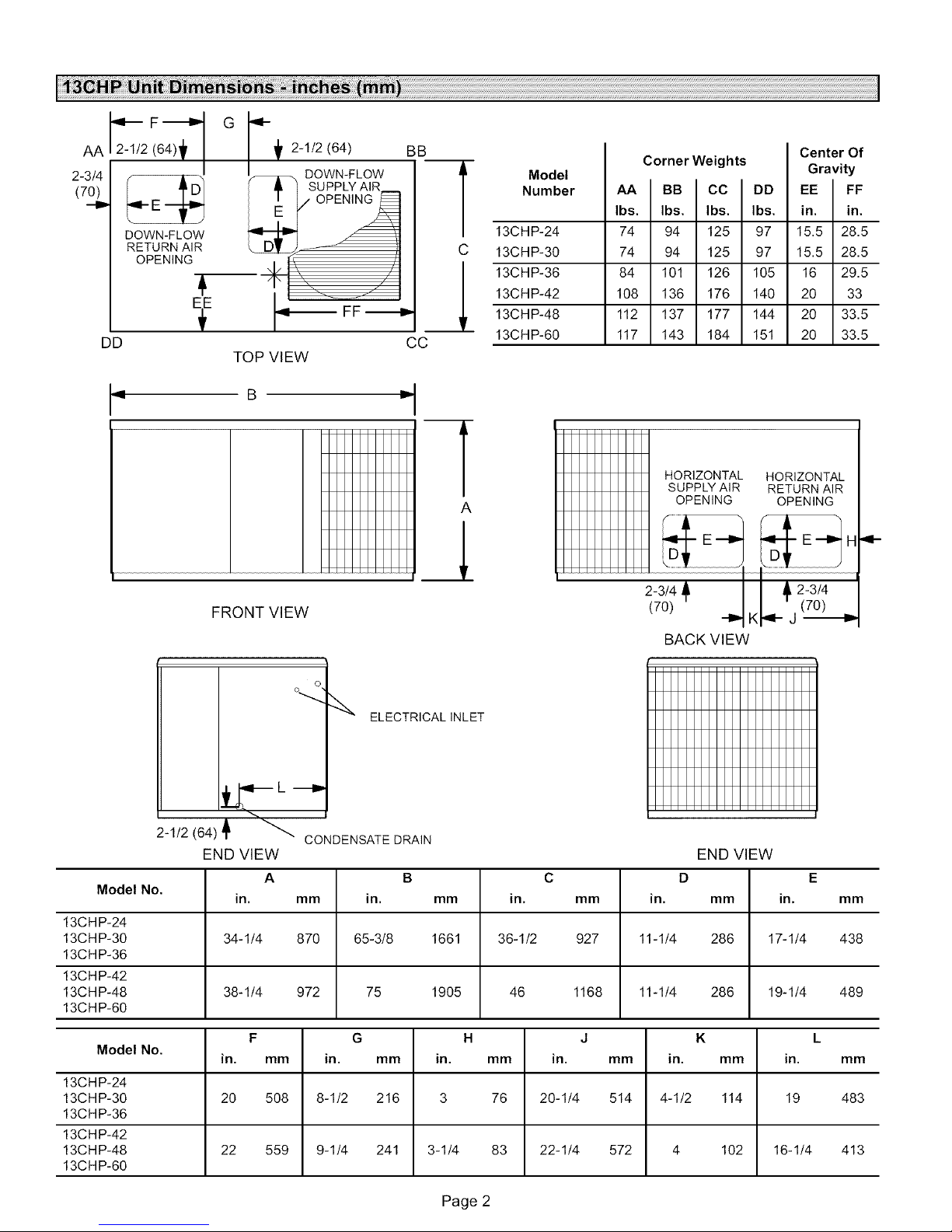
Model
Number
13CHP-24
13CHP-30
13CHP-36
13CHP-42
13CHP-48
13CHP-60
Corner Weights
74
94
74
94
84
101
108
136
112
137
117
143
HORIZONTAL HORIZONTAL
SUPPLY AIR RETURN AIR
Center Of
Gravity
125 97 15.5
125 97 15.5
126 105 16
176 140 20
177 144 20
184 151 20
FF
in.
28.5
28.5
29.5
33
33.5
33.5
FRONT VIEW
BACK VIEW
o
ELECTRICALINLET
--..,
2-1/2 (64) '_ _ CONDENSATEDRAIN
END VIEW END VIEW
Model No.
13CHP-24
13CHP-30 34-1/4 870 65-3/8 1661 36-1/2 927 11-1/4 286 17-1/4 438
13CHP-36
13CHP-42
13CHP-48 38-1/4 972 75 1905 46 1168 11-1/4 286 19-1/4 489
13CHP-60
Model No.
13CHP-24
13CHP-30 20 598 8-1/2 216 3 78 29-1/4 514 4-1/2 114 19 483
13CHP-36
13CHP-42
13CHP-48 22 559 9-1/4 241 3-1/4 83 22-1/4 572 4 102 16-1/4 413
13CHP-60
A B C D E
in. mm in. mm in. mm in. mm in. mm
F G H J K L
in. mm in. mm in. mm in. mm in. mm in. mm
Page 2
Page 3
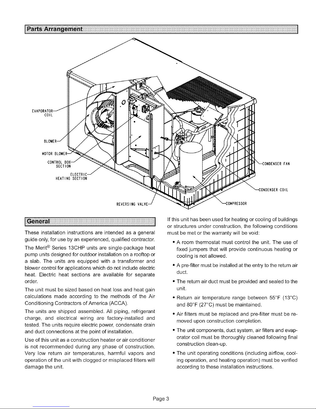
COIL
MOTOR
CONTROL B(
SECTION
HEATING SECTION
REVERSING
These installation instructions are intended as a general
guide only, for use by an experienced, qualified contractor.
The Merit® Series 13CliP units are single-package heat
pump units designed for outdoor installation on a rooftop or
a slab. The units are equipped with a transformer and
blower control for applications which do not include electric
heat. Electric heat sections are available for separate
order.
The unit must be sized based on heat loss and heat gain
calculations made according to the methods of the Air
Conditioning Contractors of America (ACCA).
The units are shipped assembled. All piping, refrigerant
charge, and electrical wiring are factory-installed and
tested. The units require electric power, condensate drain
and duct connections at the point of installation.
Use of this unit as a construction heater or air conditioner
is not recommended during any phase of construction.
Very low return air temperatures, harmful vapors and
operation of the unit with clogged or misplaced filters will
damage the unit.
FAN
COIL
If this unit has been used for heating or cooling of buildings
or structures under construction, the following conditions
must be met or the warranty will be void:
• A room thermostat must control the unit. The use of
fixed jumpers that will provide continuous heating or
cooling is not allowed,
• A pre-filter must be installed at the entry to the return air
duct,
• The return air duct must be provided and sealed to the
unit,
• Return air temperature range between 55°F (13°C)
and 80°F (27°C) must be maintained,
• Air filters must be replaced and pre-filter must be re-
moved upon construction completion,
• The unit components, duct system, air filters and evap-
orator coil must be thoroughly cleaned following final
construction clean-up.
• The unit operating conditions (including airflow, cool-
ing operation, and heating operation) must be verified
according to these installation instructions.
Page 3
Page 4
Theseunitsmustbe installedin accordancewith all
applicablenationalandlocalsafetycodes,
Theseinstructionsareintendedasageneralguideanddo
notsupersedelocalcodesinanyway,Consultauthorities
havingjurisdictionbeforeinstallation.
Ifcomponentsaretobeaddedtoaunittomeetlocalcodes,
theyaretobeinstalledatthedealer'sand/orcustomer's
expense.
Theseunitsaredesignlistedby ULin boththeUnited
StatesandCanadaasfollows:
• Foruseasaheatpump,
• Foroutdoorinstallationonly.
• Forinstallationoncombustiblematerial.
5 - The unit foundation should be raised a minimum of 3"
above finish grade, In areas which have prologed pe-
riods of temperature below freezing and snowfall,
elevate the unit above the average snow line. Take
care to allow free drainage of condensate from de-
frost cycles to prevent ice accumulation. Do not lo-
cate the unit near walkways to prevent the possible
icing of surfaces due to defrost condensate.
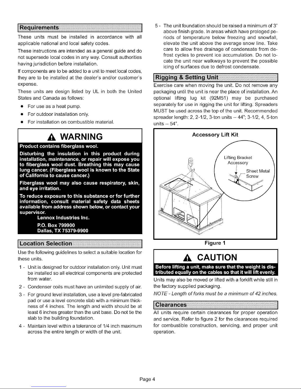
Exercise care when moving the unit. Do not remove any
packaging until the unit is near the place of installation. An
optional lifting lug kit (92M51) may be purchased
separately for use in rigging the unit for lifting. Spreaders
MUST be used across the top of the unit. Recommended
spreader length: 2, 2-1/2, 3-ton units -- 44"; 3-1/2, 4, 5-ton
units -- 54".
WARNING
Use the following guidelines to select a suitable location for
these units.
1 - Unit is designed for outdoor installation only. Unit must
be installed so all electrical components are protected
from water,
2 - Condenser coils must have an unlimited supply of air.
3 - For ground level installation, use a level pre-fabricated
pad or use a level concrete slab with a minimum thick-
ness of 4 inches. The length and width should be at
least 6 inches greater than the unit base. Do not tie the
slab to the building foundation.
4 - Maintain level within a tolerance of 1/4 inch maximum
across the entire length or width of the unit.
Accessory Lift Kit
Figure 1
CAUTION
Units may also be moved or lifted with a forklift while still in
the factory supplied packaging,
NOTE - Length of forks must be a minimum of 42 inches,
All units require certain clearances for proper operation
and service, Refer to figure 2 for the clearances required
for combustible construction, servicing, and proper unit
operation.
Page 4
Page 5

Service Clearances
3 (76)*
REAR
FRONT
48 (1219)
*Rear clearance is 18"(457)when required for
accessory maintenance.
NOTE- TopClearance - 36 in. (914 mm)
NOTE- Entire perimeter of unit base requires
support when elevated above mounting surface.
Figure 2
NOTE - Do not permit overhanging structures or shrubs to
obstruct condenser air discharge outlet.
In the U.S. units may be installed on combustible floors
made from wood or class A, B, or C roof covering material.
In Canada, units may be installed on combustible floors.
Install the unit so that snow accumulation will not restrict
the airflow. Allow a required minimum horizontal clearance
of 4 feet from electric meters, gas meters, regulators and
relief equipment. In addtion to the above requirements,
ensure that unwanted ice caused by condensate is not
allowed to accumulate around the unit. Do not locate the
unit on the side of the building where the prevailing winter
winds could trap moisture, causing it to freeze on the walls
or on overhangs (under eaves).
The 13CHP packaged heat pump may replace an existing
furnace which is being removed from a venting system
commonly run with separate gas appliances. In this case,
the existing vent system is likely to be too large to properly
vent the remaining attached appliances.
Conduct the following test while each appliance is operat-
ing and the other appliances (which are not operating) re-
main connected to the common venting system. If the
venting system has been installed improperly, you must
correct the system as indicated in the general venting re-
quirements section.
1 - Seal any unused openings in the common venting sys-
tem.
2 - Inspect the venting system for proper size and horizontal
pitch. Determine that there is no blockage, restriction,
leakage, corrosion, or other deficiencies which could
cause an unsafe condition.
3 - Close all building doors and windows and all doors be-
tween the space in which the appliances remaining
connected to the common venting system are located
and other spaces of the building. Turn on clothes dry-
ers and any appliances not connected to the common
venting system. Turn on any exhaust fans, such as
range hoods and bathroom exhausts, so they will oper-
ate at maximum speed. Do not operate a summer ex-
haust fan. Close fireplace dampers.
4 - Follow the lighting instructions. Turn on the appliance
that is being inspected. Adjust the thermostat so that
the appliance operates continuously.
5 - After the main burner has operated for 5 minutes, test
for leaks of flue gases at the draft hood relief opening.
Use the flame of a match or candle, or smoke from a
cigarette, cigar, or pipe.
6 - After determining that each appliance connected to the
common venting system is venting properly, (step 3)
return all doors, windows, exhaust fans, fireplace
dampers, and any other gas-burning appliances to
their previous mode of operation.
7 - If a venting problem is found during any of the preced-
ing tests, the common venting system must be modi-
fied to correct the problem.
Resize the common venting system to the minimum
vent pipe size determined by using the appropriate
tables in Appendix G. (These are in the current stan-
dards of the National Fuel Gas Code
ANSI-Z223.1/NFPA 54 in the USA, and the appropri-
ate Category 1 Natural Gas and Propane appliances
venting sizing tables in the current standards of the
CSA B149 Natural Gas and Propane Installation
Codes in Canada.)
Page 5
Page 6

The13CliPunitisequippedwitha3/4inchFPTcoupling
forcondensatelineconnection,Plumbingmustconformto
localcodes,Usea sealingcompoundon malepipe
threads,
Thedrainlinemustbeproperlytrappedandroutedto a
suitabledrain.Seefigure3forproperdrainarrangement,
Thedrainlinemustpitchto an opendrainor pumpa
minimumof1inchper10feettopreventcloggingofthe
line,Sealarounddrainconnectionwithsuitablematerialto
preventairleakageintoreturnairsystem.
Drainpipingshouldnotbesmallerthandrainconnectionat
coil.Anopenventindrainlinewillsometimesberequired
dueto linelength,frictionandstaticpressure.Drains
shouldbeconstructedinamannertofacilitatefutureclean-
ing,
NOTE - The condensate drain fine MUST be trapped to
provide proper drainage,
CAUTION
Typical Condensate Drain
accommodate the use of 1". 2" or 4" filters. If the optional
filter kit is not used, a filter must be field-installed,
Filters must always be installed ahead of evaporator coil
and must be kept clean or replaced, Dirty filters will reduce
the airflow of the unit, Filter sizes are shown in table 1.
Table 1
Unit Filter Size
UnitModel Filter Size Filter Quantity
-24, -30, -36 20 in. X 25 in. 1
-42, -48, -60 16 in. X 25 in. 2
The duct system should be designed and sized according
to the methods in Manual Q of the Air Conditioning
Contractors of America (ACCA).
A closed return duct system shall be used. This shall not
preclude use of economizers or outdoor fresh air intake, It
is recommended that supply and return duct connections
at the unit be made with flexible joints,
The supply and return air duct systems should be
designed for the CFM and static requirements of the job,
They should NOT be sized by simply matching the
dimensions of the duct connections on the unit.
Ducting installed outdoors MUST be insulated and
waterproofed.
1 in. (25 ram) per
10' (3 m) of line
Minimum Pitch
open
ve;tII
Trap must be deep enough to offset maximum mounting
static difference(Generally,3 inches minimum), frame
Figure 3
Filters are not factory-supplied with the unit; however,
optional internally installed filter kits are available. Filter kit
92M54 is used with 2, 2-1/2 and 34on units. Filter kit 92M55
is used with 3-1/2, 4 and 5-ton units. The filter kits
CAUTION
The 13CHP unit is shipped ready for horizontal air
discharge (side duct connections). If bottom air discharge
is desired, the covers must be removed from the supply
and return air openings on the bottom of the unit and
re-installed to cover the side openings.
Removing Supply and Return
Air Opening Covers
®
®
1. Remove screw and lift.
2. Slide cover to free back pin.
Figure 4
Base-_ d
Page 6
Page 7

Units are shippedwith the compressormountings
factory-adjustedandreadyforoperation,
All wiring should be done in accordance with the
current National Electric Code ANSI/NFPA No. 70 in the
United States. In Canada, wiring must be done in
accordance with the current CSA C22.2 Part 1. Local
codes may take precedence.
Use wiring with a temperature limitation of 75_C min.; run
the 208 or 230 volt, 60 hertz electric power supply through a
fused disconnect switch to control box of unit and connect
as shown in the wiring diagram located on the inside of the
control access panel. Refer to figure 5 for electrical access.
Electrical Access
CONDUCTORS ONLY. Each unit must be wired with a
separate branch circuit and be properly fused.
WARNING
CAUTION
WARNING
Thermostat _
Entry / •
Line Voltage
Entry
Figure 5
Unit must be electrically grounded in accordance with local
codes or in the absence of local codes with the National
Electric Code, ANSI/NFPA No, 70 (latest edition) or CSA
C22.2 Part 1 (latest edition).
Power supply to the unit must comply with all applicable
codes and NEC or CEC. A fused disconnect switch should
be field provided for the unit. The switch must be separate
from all other circuits. If any of the wire supplied with the
unit must be replaced, replacement wire must be of the
type shown on the wiring diagram,
Electrical wiring must be sized to carry minimum circuit
ampacity marked on the unit, USE COPPER
See figure 7 for typical field wiring connections and figure 8
for typical unit wiring diagram.
Optional Electric Heat
Optional electric heat is available and must be purchased
separately. Install the electric heat section as outlined in the
installation instructions packaged with the electric heat
section,
Thermostat
The room thermostat should be located on an inside wall
where it will not be subject to drafts, sun exposure or heat
from electrical fixtures or appliances. Follow
manufacturer's instructions enclosed with thermostat for
general installation procedure, Color coded insulated wires
(# 18 AWG) should be used to connect thermostat to unit,
Six wires are required for heat pump operation (including a
common wire, if required by the thermostat).
Blower Control Board
The circulating air blower is controlled by a blower control
board located in the unit control box. Blower operation is
NOT delayed after a call for either heating or cooling, A
blower "off" delay of 90 seconds begins when the
thermostat demand is satisfied. These delays are not
adjustable. See figure 6.
Page 7
Page 8

Blower Drive Control
RiO
R7
@ R6
i)°<_>
QI R4 @
RS @
R1
RII
Figure 6
C2 _ D3 3 _N_X
Z1 _ D1
dl]d3 IdS
R5 0
D5 OWl C3_ _/ _:X
Z2
@
1005 83 175 x
HSC]
3
Typical Single-Phase Unit Wiring Connections
THE_X_T_
[]
_N_LLED
®
[]
-JJ_
_D_JMD
Figure 7
Page 8
Page 9

r_
C.D
GO
SLQ!fl[R SPEED CHART
UNIT F.IEIOI Y _IIIPI_I) _q*ll_
CO01.I _ I IIPUT (DtX)
24 LOg
30 MUD
36 HiGH
42 LOg
48 MUD
60 HiGH
MOTOR
_PEED TAPe/
LI (_ KH
COMPRESSOR
"_ CONTACTOR
?O8/RSOV-l-6O
81
BLN
r
COMPRESSOR
L2
13CHP Series Packaged Heat Pump Units
Typical Wiring Diagram
_A(_OST/CD_W.AY
NoPo_r to Control
MorMt _wrotieo I Po_r to
Coltrol
A_ti-Sbort Cycle Lockout
LowPressure Switch Fault
LowPros=Ire _itch Locko=t
High Pro#lure Switch Fault
High Pressure Switch Lochemt
P-I
< _------
SEE CHART--_
UNCl FOR WIRIRG_
DEFROST
DUAL CONTROL
CAPACITOR
CI2[--.-.-.-.-.-..¢%-3BAS
t j PUN
CONDENSER
:AN MOTOR
KI'?
OFF OFF
SimettoneousSlowFloss
bib€riots Slow Flash
OFF Stowt'to_h
OFF ON
StowFto#h OFF
ON OFf
i
P-D
BLO_ER
CONTROL
l
CAPAOITOB
P-2
<<
INDOOR
BLOWER
MOTOR
Note: Secol=e the Pre_l_e SlitChll ere monitored omly then "Yl' (Imp=It il o(til+_ the €Ode
for pressure +witch opel will not be seenwhen+Yt" is oft. lanced, the "Morro<ItOporotio," or
"Aett Short Cycle" codewill be #wen,
Also. wheno pressure =lilts opeR_andcou_edo short cycle lockout, the pressure _litoh+epe,
code wilt be seen until it €loven. then the short cycle Iockolt codewill tlo_h nloss it So=already
expired.
) >
All
WI & WE CA# BE USED TO STAGE
ELECTRIC HEAT ACCESSORY ON
IS & EOKW MODELS
5+ 7,G & IO_W HEATER ACCESSC431US
FUNCTION 01oF II ONLY+
THERMOSTAT
CONTACTOR
YEL
+ REV.VALVE
K
PRESSU_ L I_]-'_io_
_I _w,+c, S79_
(IF +SES)
l I T'STAT_ /Oi-i
_OL
11
P_4
FAN
O_OUT
_PS+
Z4V
+Tl OUT Y
'_- Ps,'_
CMCI
_FRD_TCOnTrOL
NOTE:
IF ANT OF THE ORiGiNAL
GRN
P+6
P-5
RED
ORN
LINE VOLTAGE FIELD INSTALLED
WIRE 1S REPLACED THE
SAME SIZE AND TYPE WIRE
MUST BE USED+
USE COPPER CONDUCTOR
ONLY, MIN TS"C WIRE
z_CONNECTION MUST BE JUMPEREDWHEN PRESSURE SWITCH iS NOT USED.
WARNING-
ELECTRIC SHOCK HAZARD_ UNIT
MUST BE GROUNDED IN ACCORDANCE
WiTH NATIONAL AND LOCAL CODES,
Page 10

13CHP units are equipped with a defrost control board that
includes the combined functions of time/temperature de-
frost control, defrost relay, diagnostic LEDs and a low volt-
age terminal strip. See figure 9.
The control provides automatic switching from normal
heating operation to defrost mode and back. During the
compressor cycle (call for defrost), the control accumu-
lates compressor run time at 30, 60 or 90-minute field-ad-
justable intervals. If the defrost thermostat is closed when
the selected compressor run time interval ends, the defrost
relay is energized and the defrost begins.
The defrost timing jumper is factory-installed to provide a
60-minute defrost interval. If the timing selector jumper is
not in place, the control defaults to a 90-minute defrost in-
terval. The maximum defrost period is 14 minutes and is
not adjustable. See figure 9 for the location of the defrost
interval timing pins.
A test option is provided for troubleshooting. The test
mode may be started any time the unit is in the heating
mode and the defrost thermostat is closed or jumpered. If
the jumper is in the TEST position at power up, the control
will ignore the test pins. When the jumper is placed across
the TEST pins for 2 seconds, the control will enter the de-
frost mode. If the jumper is removed before an additional
5-second period has elapsed (7 seconds total), the unit
will remain in defrost mode until the defrost thermostat
opens or 14 minutes have passed. If the jumper is not re-
moved until after the additional 5-second period has
elapsed, the defrost will terminate and the test option will
not function again until the jumper is removed and reap-
plied.
The defrost control board includes a compressor delay
function which cycles the compressor off for 30 seconds
while going into and coming out of the defrost cycle. This
function is activated when the jumper is removed from the
compressor delay pins.
NO TE -- The 30-second compressor delay is not function-
al when the TEST pins are jumpered.
Defrost Control Board
Defrost Interval
Timing Pins
Test Pins
Compressor
Delay Pins
Reversing Valve -
Low Pressure/
Loss of Charge --
Switch
Defrost T'stat j
High Pressure i
Switch
PI (_ FAll
- LO*PS
_Diagnostic
LEDs
24V Terminal
Strip
Connections
Figure 9
The defrost thermostat is located on the liquid line be-
tween the check/expansion valve and the distributor.
When the defrost thermostat senses a liquid line tempera-
ture of 42°F or cooler, the thermostat contacts close and
send a signal to the defrost control board to begin the de-
frost timing. The defrost thermostat also terminates the
defrost when the liquid line temperature warms to 70°F.
The defrost control board includes HI-PS and LO-PS ter-
minals to receive signals from the optional high pressure
switch and loss of charge switch. These optional switches
must be ordered separately and field-installed,
During a single demand cycle, the defrost control locks
out compressor operation after the fifth time that the cir-
cuit is interrupted by any pressure switch wired to the con-
trol board. In addition, the diagnostic LEDs indicate a
locked-out pressure switch after the fifth open pressure
switch occurrence, Compressor operation remains
locked out until power to the board is interrupted, then re-
established, or until the jumper is applied to the TEST pins
for 0,5 seconds,
NOTE -- The defrost control board ignores input from the
optional loss of charge switch terminals as follows:
During the test mode;
During the defrost cycle;
During the 90-second start-up period;
During the first 90 seconds following
a reversing valve switch between the
heating and cooling modes.
The defrost control board includes two diagnostic
LEDs. LED codes indicate operating status. The diag-
nostics codes are given in table 2.
Table 2
Defrost Control Board Diagnostic LEDs
Mode Green LED Red LED
(DS2) (DS1)
No power to OFF OFF
board
Normal
Operation / Simultaneous Slow Flash
Power to Board
Anti-Short Cycle Alternating Slow Flash
Lockout
Loss of Charge
Pressure Switch OFF Slow Flash
Fault*
Loss of Charge
Pressure Switch OFF ON
Lockout*
High Pressure Slow Flash OFF
Switch Fault*
High Pressure ON OFF
Switch Lockout*
* These fault codes require installation of optional loss
of charge and high pressure switches.
Page 10
Page 11

Each13CHPpackagedheatpumpisfactory-chargedwith
R-22refrigerant.Thecompressorishermeticallysealed,
internallysprungandbase-mountedwithrubber-insulated
hold-downbolts,
Pre-Start Check List:
1 - Make sure refrigerant lines do not rub against the cabi-
net or each other.
2- Inspect all electrical wiring, both factory- and field-
installed, for loose connections.
3 - Check voltage at the disconnect switch. Voltage must
be within the range listed on the unit nameplate. If not,
consult power company and have voltage condition
corrected before starting unit.
4 - Recheck voltage with unit running. If power is not with-
in the range listed on the unit nameplate, stop the unit
and consult the power company. Check unit amper-
age. Refer to unit nameplate for correct running amps.
5 - Make sure filter is in place before unit start-up.
6 - Before placing the unit into full operation, energize the
unit for three false starts. Energize the compressor
just long enough for it to make a few revolutions, wait
five to seven minutes before repeating a second and
third time.
Cooling Sequence of Operation
When the thermostat calls for cooling, the "O" circuit is
energized to activate the reversing valve, The "R" to "Y"
circuit is closed to energize the compressor contactor. The
contactor brings on both the compressor and outdoor fan,
The thermostat also closes the "R" to "G" circuit to energize
the circulating air blower, When the cooling demand is
satisfied, the thermostat opens the circuits, as well as the
compressor contactor. The compressor and outdoor fan
immediately stop. The circulating air blower continues
operating through a 90-second delay,
Unit compressors have internal protection. If there is an
abnormal rise in the compressor temperature, the
protector will open and the compressor will stop.
Heating Sequence of Operation
When the thermostat calls for heating, the "R" to "Y" circuit
is closed to energize the compressor contactor. The
contactor brings on both the compressor and outdoor fan.
The reversing valve is not energized in the heating mode.
The thermostat also closes the "R" to "G" circuit to energize
the circulating air blower. When the heating demand is
satisfied, the thermostat opens these circuits, as well as
the compressor contactor. The compressor and outdoor
fan immediately stop. The circulating air blower continues
operating through a 90-second delay.
System Performance
System subcooling values are given in table 3.
Table 3
Subcooling Values
Cooling Mode Heating Mode
Unit Model No. Subcooling Value Subcooling Value
13CHP-24 10"F 20"F
13CHP-30 10_'F 15°F
13CHP-36 20_'F 15°F
13CHP-42 7°F 30°F
13CH P-48 7 _'F 25 ° F
13CH P-60 7 _'F 25 ° F
Verify system performance using table 4 and table 5 as a
general guide. Minor variations in these pressures may be
expected due to differences in installations. Significant dif-
ferences could mean that the system is not properly
charged or that a problem exists with some component in
the system.
Used carefully, these tables could serve as a useful service
guide. Data is based on 80°F dry bulb / 67°F wet bulb return
air. Allow unit operation to stabilize before taking pressure
readings.
Page 11
Page 12

Table 4
Cooling Mode -- Normal Operating Pressures
80°F db/67°F wb RETURN AIR Air Temperature Entering Outdoor Coil(°F)
UNIT PRESSURE 65 70 75 80 82 85 90 95 100 105 110 115
13CHP-24 70 73 75 78 79 80 82 86 86 88 90 93
13CHP-30 76 77 78 79 79 80 80 81 82 83 84 85
13CHP-36 88 88 88 89 89 89 89 90 88 88 88 88
13CHP-42 85 85 85 85 85 85 84 85 83 83 82 82
13CHP-48 79 80 81 82 82 82 83 84 84 84 85 85
13CHP-60 81 82 83 84 84 84 85 86 86 86 87 87
13CHP-24 138 152 166 179 185 193 207 221 235 246 263 277
13CHP-30 141 156 171 187 193 203 219 233 251 264 283 300
13CHP-36 141 158 176 193 200 211 230 245 267 282 304 323
13CHP-42 Liquid 135 150 165 179 185 194 219 223 238 250 268 283
13CHP-48 139 154 169 184 190 200 214 229 247 260 279 295
13CHP-60 146 162 179 195 202 213 230 245 266 280 301 319
Suction
Table 5
Heating Mode -- Normal Operating Pressures
70°F RETURN AIR
UNIT
13CHP-24
13CHP-30
13CHP-36
13CHP-42
13CHP-48
13CHP-60
13CHP-24
13CHP-30
13CHP-36
13CHP-42
13CHP-48
13CHP-60
PRESSURE 0 5 10 17 20 25 30 35 40 45 50 55 60
18 22 27 33 36 40 45 49 54 106 110 118 125
14 19 23 30 33 37 42 47 51 104 109 116 124
Suction
Liquid 135 146 158 174 181 192 204 215 227 243 250 261 273
5 11 17 25 29 34 40 46 52 101 105 113 120
15 19 24 31 34 39 44 48 53 107 112 120 127
16 20 24 30 33 37 41 45 49 102 107 114 122
5 10 15 22 25 30 35 40 45 97 101 108 116
157 164 170 180 184 191 198 205 211 221 225 232 239
146 152 158 167 171 177 183 189 195 204 208 214 220
153 159 164 171 174 179 184 190 195 202 205 210 215
128 142 156 175 183 197 211 225 239 258 266 2860 294
160 165 170 177 180 185 190 195 200 207 210 215 220
Air Temperature Entering Outdoor Coil (°F)
Motors
Indoor, outdoor fan and vent motors are permanently
The top of the condenser fan should be 1-1/2 inchs from the
bottom of the top grille. This dimension should be checked
and the fan should be adjusted accordingly any time servic-
ing of the outdoor fan system is required.
lubricated and require no further lubrication. Motors
should be cleaned yearly to prevent the accumulation of
dust and dirt on the windings or motor exterior.
Coil
Dirt and debris should not be allowed to accumulate on the
coil surfaces or other parts in the air conditioning circuit.
Cleaning should be performed as often as necessary. Use
Periodic inspection and maintenance normally consists of
changing or cleaning filters and (under some conditions)
cleaning the main burners.
Filters
Not supplied. Inspect once a month. Replace disposable or
clean permanent type as necessary. DO NOT replace per-
manent type with disposable.
a brush, vacuum cleaner attachment, or other suitable
means. If water is used to clean the coil, be sure the power
to unit is shut off prior to cleaning.
NOTE - Care should be used when cleaning the coil so that
the coil fins are not damaged.
Do not permit the hot condenser air discharge to be ob-
structed by overhanging structures or shrubs.
Filter Kit (2-ton to 3-ton capacity units)
Filter Kit (3-1/2-ton to 5-ton capacity units)
Description
Accessories
LENNOX Cat.
Number
92M54
92M55
Page 12
 Loading...