

Lennox Merit 10HPB Series, 10HPB18, 10HPB24, 10HPB30, 10HPB36 Installation Instructions Manual
...
Page 1
504,828M
*P504828M*
06/04
*2P0604*
2003 Lennox Industries Inc.
Dallas, Texas, USA
®
10HPB Outdoor Units
Lennox Merit® Series 10HPB outdoor units are approved
and warranted only for installation with specially matched
indoor coils, line sets, and refrigerant control systems as
designated by Lennox. Refer to Lennox Engineering
Handbook for expansion valve kits which must be ordered
separately.
Shipping and Packing List
1 − Assembled 10HPB outdoor unit
1 − Coupling (18, 24 and 30)
Check unit for shipping damage. Consult last carrier immediately if damage is found.
WARNING
Improper installation, adjustment, alteration, service
or maintenance can cause property damage, personal injury or loss of life. Installation and service must
be performed by a qualified installer or service
agency.
IMPORTANT
The Clean Air Act of 1990 bans the intentional venting of refrigerant (CFC’s and HCFC’s) as of July 1,
1992. Approved methods of recovery, recycling or
reclaiming must be followed. Fines and/or incarceration may be levied for noncompliance.
INSTALLATION
INSTRUCTIONS
10HPB Series Units
HEAT PUMP UNITS
1−1/2 through 5 tons
504,828M
06/04
Supersedes 02/04
Table of Contents
10HPB Outdoor Units 1. . . . . . . . . . . . . . . . . . . . . . . . . . .
Shipping & Packing List 1. . . . . . . . . . . . . . . . . . . . . . . . .
General Information 1. . . . . . . . . . . . . . . . . . . . . . . . . . . .
Unit Dimensions 2. . . . . . . . . . . . . . . . . . . . . . . . . . . . . . .
Setting the Unit 3. . . . . . . . . . . . . . . . . . . . . . . . . . . . . . . .
Electrical 4. . . . . . . . . . . . . . . . . . . . . . . . . . . . . . . . . . . . . .
Refrigerant Piping 6. . . . . . . . . . . . . . . . . . . . . . . . . . . . . .
Refrigerant Metering Device 10. . . . . . . . . . . . . . . . . . . .
Manifold Gauge Set 10. . . . . . . . . . . . . . . . . . . . . . . . . . .
Service Valves 11. . . . . . . . . . . . . . . . . . . . . . . . . . . . . . . .
Leak Testing 12. . . . . . . . . . . . . . . . . . . . . . . . . . . . . . . . . .
Evacuation 13. . . . . . . . . . . . . . . . . . . . . . . . . . . . . . . . . . .
Start−Up 13. . . . . . . . . . . . . . . . . . . . . . . . . . . . . . . . . . . . . .
Charging 14. . . . . . . . . . . . . . . . . . . . . . . . . . . . . . . . . . . . .
System Operation 16. . . . . . . . . . . . . . . . . . . . . . . . . . . . .
Defrost System 16. . . . . . . . . . . . . . . . . . . . . . . . . . . . . . .
Maintenance 18. . . . . . . . . . . . . . . . . . . . . . . . . . . . . . . . . .
Optional Accessories 18. . . . . . . . . . . . . . . . . . . . . . . . . .
Start−Up and Performance Check List 18. . . . . . . . . . . .
RETAIN THESE INSTRUCTIONS
FOR FUTURE REFERENCE
General Information
These instructions are intended as a general guide and do
not supersede national or local codes in any way. Authorities having jurisdiction should be consulted before installation.
WARNING
This product and/or the indoor unit it is matched with
may contain fiberglass wool.
Disturbing the insulation during installation, maintenance, or repair will expose you to fiberglass wool
dust. Breathing this may cause lung cancer. (Fiberglass wool is known to the State of California to
cause cancer.)
Fiberglass wool may also cause respiratory, skin,
and eye irritation.
To reduce exposure to this substance or for further
information, consult material safety data sheets
available from address shown below, or contact your
supervisor.
Lennox Industries Inc.
P.O. Box 799900
Dallas, TX 75379−9900
Litho U.S.A.
Page 2
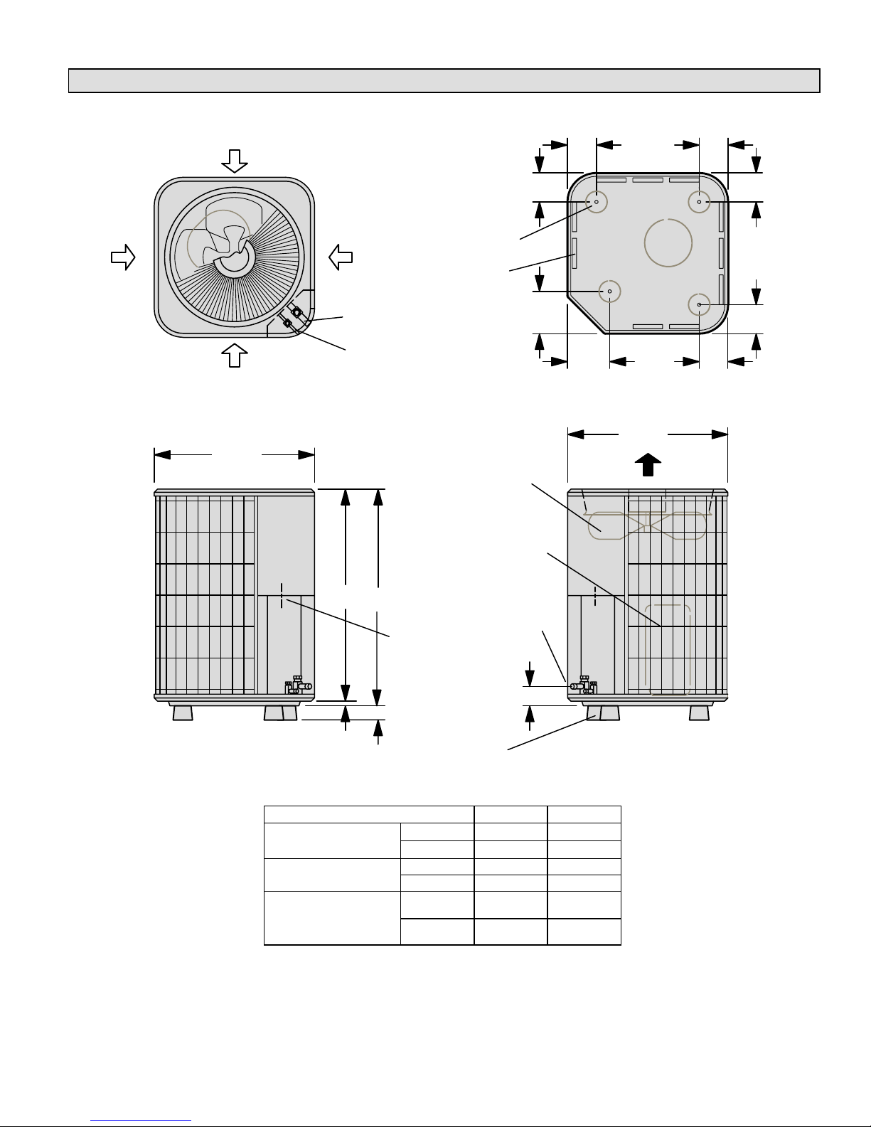
10HPB Unit Dimensions − inches (mm)
Side View
vapor &
liquid line
connection
discharge air
Side View
Top View
A
outdoor
coil fan
compressor
inlet
air
B
24-1/4
(616)
2-3/4 (70)
24-1/4
(616)
electrical
inlets
optional unit
stand-off kit (4)
(field−installed)
4-3/8
(111 )
6-3/8
(162)
6-3/8
(162)
Top View Base Section
3/4
(19)
4-3/8
(111 )
4-3/8
(111)
4-3/8
(111 )
4-3/8
(111 )
4-3/8
(111 )
coil drain outlets
(around perimeter of base)
optional unit
stand-off kit (4)
(field−installed)
liquid line
connection
vapor line
connection
2 (51)
COMPRESSOR
inlet
air
inlet
air
inlet
air
Model No.
A B
10HPB18
in. 25 24-1/4
10HPB18
10HPB24
mm 635 616
in. 29 28-1/4
10HPB30
mm 737 718
10HPB36
10HPB42
in. 33 32-1/4
10HPB42
10HPB48
10HPB60
mm 838 819
Page 3
Setting the Unit
CAUTION
In order to avoid injury, take proper precaution when
lifting heavy objects.
CAUTION
Sharp sheet metal edges can cause injury. When
installing the unit, avoid accidental contact with
sharp edges.
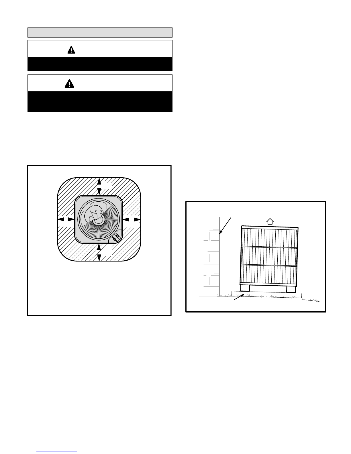
These units operate under a wide range of weather conditions; therefore, several factors must be considered when
positioning the outdoor unit. The unit must be positioned to
give adequate clearances for sufficient airflow and servicing. A minimum clearance of 24 inches (610 mm) between
multiple units must be maintained. Refer to figure 1 for
installation clearances.
see
note
Installation Clearances
see
note
NOTE − A service clearance of 30" (762 mm) must be maintained on one of the sides adjacent to the control box. Clearance to one of the other three sides must be 36" (914 mm).
Clearance to one of the remaining two sides may be 12" (304
mm) and the final side may be 6" (152 mm).
see
note
NOTE − A clearance of 24" (610 mm) must be maintained
between two units.
NOTE − 48" (1219 mm) clearance required on top
of unit. Maximum soffit overhang is 36" (914 mm).
see
note
Figure 1
1 − Place a sound-absorbing material, such as Isomode,
under the unit if it will be installed in a location or position that will transmit sound or vibration to the living
area or adjacent buildings.
2 − Install the unit high enough above the ground or roof to
allow adequate drainage of defrost water and prevent
ice buildup.
3 − In heavy snow areas, do not locate the unit where drift-
ing will occur. The unit base should be elevated above
the depth of average snows.
NOTE − Elevation of the unit may be accomplished by
constructing a frame using suitable materials. If a support frame is constructed, it must not block drain holes
in unit base.
4 − When installed in areas where low ambient tempera-
tures exist, locate unit so winter prevailing winds do not
blow directly into outdoor coil.
5 − Locate unit away from overhanging roof lines which
would allow water or ice to drop on, or in front of, coil or
into unit.
Slab Mounting − Figure 2
When installing a unit at grade level, the top of the slab
should be high enough above the grade so that water from
higher ground will not collect around the unit. See figure 2.
Slab should have a slope tolerance away from the building
of 2 degrees or 2 inches per 5 feet (51 mm per 1524 mm).
This will prevent ice from building up under the unit during a
defrost cycle. Refer to roof mounting section for barrier
construction if unit must face prevailing winter winds.
Figure 2
Slab Mounting At Ground Leve
l
discharge air
Mounting slab must slope
away from building.
ground level
structure
Roof Mounting − Figure 3
Install the unit a minimum of 6 inches (152 mm) above the
roof surface to avoid ice build−up around the unit. Locate
the unit above a load bearing wall or area of the roof that
can adequately support the unit. Consult local codes for
rooftop applications.
Page 4
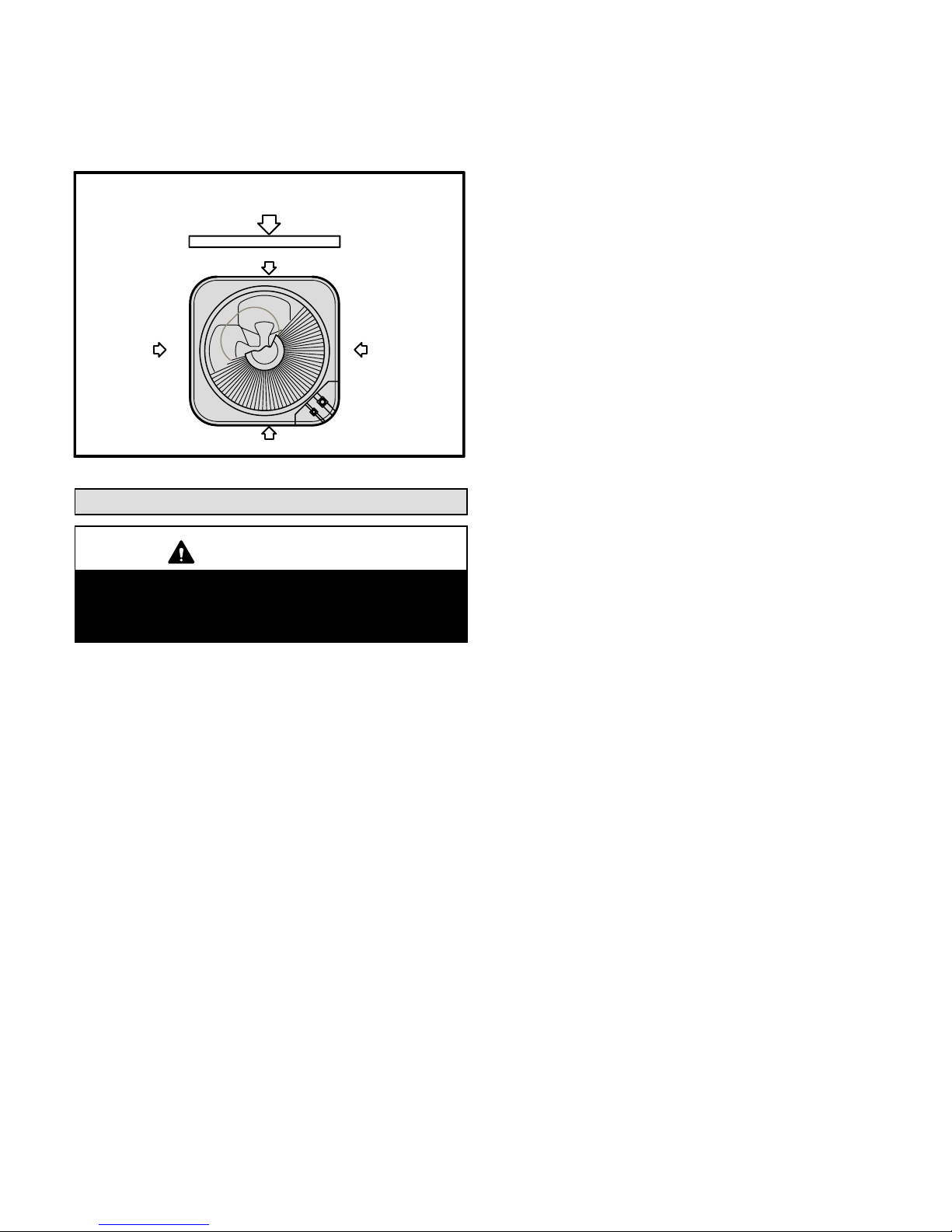
If unit coil cannot be mounted away from prevailing winter
winds, a wind barrier should be constructed. Size barrier at
least the same height and width as outdoor unit. Install barrier 24 inches (610 mm) from the sides of the unit in the direction of prevailing winds.
wind barrier
inlet air
inlet air
inlet air
inlet air
prevailing winter winds
Rooftop Application
Wind Barrier Construction
Figure 3
Electrical
WARNING
Unit must be grounded in accordance with national
and local codes.
Electric Shock Hazard.
Can cause injury or death.
1 − Install line voltage power supply to unit from a properly
sized disconnect switch.
2 − Ground unit at unit disconnect switch or to an earth
ground.
NOTE − To facilitate conduit, a hole is in the bottom of
the control box. Connect conduit to the control box us
ing a proper conduit fitting.
NOTE − Units are approved for use only with copper
conductors.
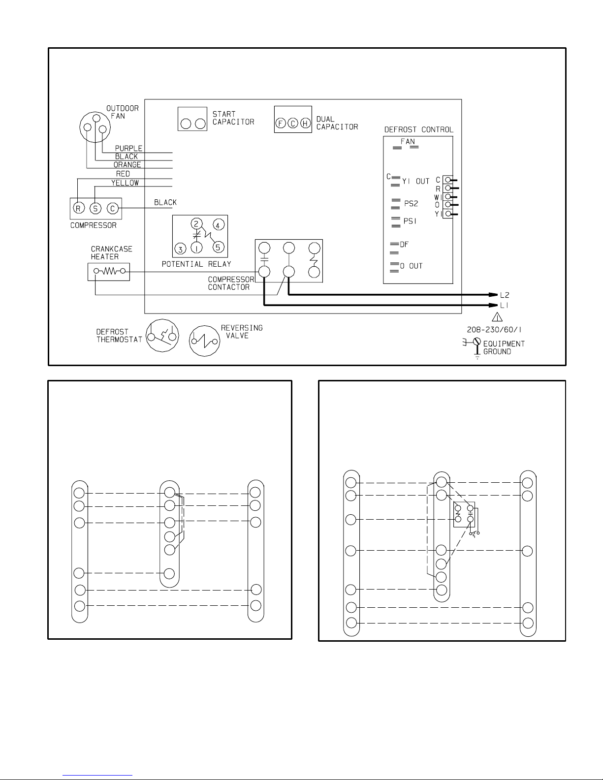
24V, Class II circuit connections are made in the low
voltage junction box. Refer to figure 4 for field wiring
diagram.
NOTE − A complete unit wiring diagram is located in
side the unit control box cover.
3 − Install room thermostat (ordered separately) on an in-
side wall approximately in the center of the conditioned
area and 5 feet (1.5 m) from the floor. It should not be
installed on an outside wall or where it can be effected
by sunlight, drafts or vibrations.
4 − Install voltage wiring from outdoor to indoor unit and
from thermostat to indoor unit. See figures 5 and 6.
Page 5
Typical Wiring Field Wiring Diagram
Figure 4
*
*
*May be optional
R
C
W1
Y1
O
G
R
C
W1
W2
W3
G
reversing valve
10HPB and Blower Unit
Thermostat Designations
(Some connections may not apply.
Refer to specific thermostat and indoor unit.)
Thermostat
Indoor
Unit
R
C
W1
Y1
O
Outdoor
Unit
Figure 5
power
power
common common
1st. stage aux. heat
1st. stage aux. heat
indoor blower
compressor
R
C
W1
Y1
O
G
R
C
W1
W2
W3
G
10HPB and Blower Unit
Thermostat Designations
(with auxiliary heat)
(Some connections may not apply.
Refer to specific thermostat and indoor unit.)
Thermostat
Indoor
Unit
Outdoor
Unit
E
R
C
W1
Y1
O
reversing valve
indoor blower
compressor
power
power
common common
1st. stage aux. heat
1st. stage aux. heat
emergency heat
Figure 6
Page 6
Refrigerant Piping
Field refrigerant piping consists of liquid and vapor lines
from the outdoor unit (sweat connections) to the indoor coil
(flare or sweat connections). Use Lennox L15 (sweat, nonflare) series line sets as shown in table 1 or use field-fabricated refrigerant lines. Refer to Refrigerant Piping Guide
(Corp. 9351−L9) for proper size, type, and application of
field−fabricated lines. Valve sizes are also listed in table 1.
Table 1
Refrigerant Line Sets
Valve Field Size
Connections
Recommended Line Set
Model
Liquid
Line
Vapor
Line
Liquid
Line
Vapor
Line
L15
Line Sets
−18
3/8 in.
(10 mm)
5/8"
(15.9 mm)
5/16"*
(7.9 mm)
5/8"
(15.9
mm)
L15−21
15 ft. − 50 ft.
(4.6 m − 15
m)
−24
−30
3/8 in.
(10 mm)
3/4"
(19 mm)
5/16"*
(7.9 mm)
3/4"
(19 mm)
L15−31
15 ft. − 50 ft.
(4.6 m − 15 m)
−36
3/8 in.
(10 mm)
3/4"
(19 mm)
3/8"
(9.5 mm)
3/4"
(19 mm)
L15−41
15 ft. − 50 ft.
(4.6 m − 15 m)
−42
−48
3/8 in.
(10 mm)
7/8"
(22.2 mm)
3/8"
(9.5 mm)
7/8"
(22.2
mm)
L15−65
15 ft. − 50 ft.
(4.6 m − 15 m)
−60
3/8 in.
(10 mm)
1−1/8"
(28.5 mm)
3/8"
(9.5 mm)
1−1/8"
(28.5
mm)
Field
Fabricated
*Use reducer supplied in bag assembly
NOTE − Units are designed for line sets of up to fifty feet (15
m). For applications longer than fifty feet, consult the Len-
nox Refrigerant Piping Guide (Corp. 9351−L9). Select line
set diameters from table 1 to ensure that oil returns to the
compressor.
Installing Refrigerant Line
During the installation of any heat pump or a/c system, it is
important to properly isolate the refrigerant lines to prevent
unnecessary vibration. Line set contact with the structure
(wall, ceiling or floor) causes some objectionable noise
when vibration is translated into sound. As a result, more
energy or vibration can be expected. Closer attention to
line set isolation must be observed.
Following are some points to consider when placing and
installing a high−efficiency outdoor unit:
1- Placement − Be aware some localities are adopting
sound ordinances based on how noisy the unit is from
the adjacent property not at the original installation.
Install the unit as far as possible from the property line.
When possible, do not install the unit directly outside a
window. Glass has a very high level of sound transmission.
2- Line Set Isolation − The following illustrations demon-
strate procedures which ensure proper refrigerant line
set isolation. Figure 7 shows how to install line sets on
vertical runs. Figure 8 shows how to install line sets on
horizontal runs. Figure 9 shows how to make a transition
from horizontal to vertical. Finally, figure 10 shows how
to place the outdoor unit and line set.
 Loading...