

Lennox MPA048S4S-*P, MCFA024S4-*P, MPB024S4S-*P, MPA036S4S-*P, MPB036S4S-*P Installation Instructions Manual
...Page 1
INSTALLATION
©
2017 Lennox Industries Inc.
Dallas, Texas, USA
Table of Contents
General ...........................................................................1
Included Parts.................................................................2
Indoor / Outdoor Unit Match-Ups....................................2
Model Number Identication ...........................................3
Typical Single-Zone System Components......................4
System Dimensions .......................................................5
Outdoor Units ..............................................................5
Indoor Units .................................................................6
System Clearances ........................................................6
Outdoor Unit ................................................................6
Indoor Unit ...................................................................7
Torque Requirements for Caps and Fasteners...............7
Indoor Unit Installation ....................................................7
Unit Placement Considerations ...................................7
Floor Installation ..........................................................8
Ceiling Installation .......................................................8
Indoor Unit Condensate Piping Connections ...............9
Outdoor Unit Installation ...............................................10
Placement Considerations .........................................10
Direct Sunlight, Rain, Snow and Ice Protection .........10
Prevailing Winds ........................................................11
Buried Refrigerant Pipe Protection ............................12
Outdoor Unit Condensate Piping ...............................12
Securing the Outdoor Unit .........................................12
Refrigerant Piping Connections ....................................13
Leak Test and Evacuation ............................................14
Leak Test ...................................................................14
Triple Evacuation Procedure......................................14
Wiring Connections ......................................................15
Outdoor Unit .............................................................15
Indoor Unit .................................................................15
Unit Start-Up .................................................................23
Adding Refrigerant for Longer Line Set ........................23
Troubleshooting ............................................................23
Test Run .......................................................................23
Pre-Checks ................................................................23
Procedure ..................................................................23
Dry Mode Operation (Dehumidication) .......................24
Procedure ..................................................................24
Sequence of Operation ..............................................24
INSTRUCTIONS
MLA/MPA/MPB and
MCFA/MCFB Series
SINGLE-ZONE MINI-SPLIT SYSTEMS
(208/230V) --
Ceiling / Floor Indoor Units
507548-06
4/2017
Supersedes 10/2016
THIS MANUAL MUST BE LEFT WITH THE OWNER
FOR FUTURE REFERENCE
WARNING
Improper installation, adjustment, alteration, ser vice or
maintenance can cause property damage, personal
injury or loss of life.
Installation and service must be performed by a li censed
professional HVAC installer (or equivalent) or a service
agency.
WARNING
The clean Air Act of 1990 bans the intentional venting of
refrigerant (CFCs, HCFCs, and HFCs) as of July, 1992.
Approved methods of recovery, recycling or reclaiming
must be followed. Fines and/or incarceration may be
levied for non-compliance.
WARNING
This product contains a chemical known to the State
of California to cause cancer, birth defects, or other
reproductive harm.
CAUTION
As with any mechanical equipment, contact with sharp
sheet metal edges can result in personal injury. Take
care while handling this equipment and wear gloves and
protective clothing.
General
Refer to the Product Specications bulletin (EHB) for more
product information.
These instructions are intended as a general guide and
do not supersede local or national codes in any way.
Authorities having jurisdiction should be consulted before
installation.
The MCFA and MCFB Ceiling/Floor indoor units are
matched with an outdoor heat pump unit to create a minisplit system that uses HFC-410A refrigerant.
Page 2
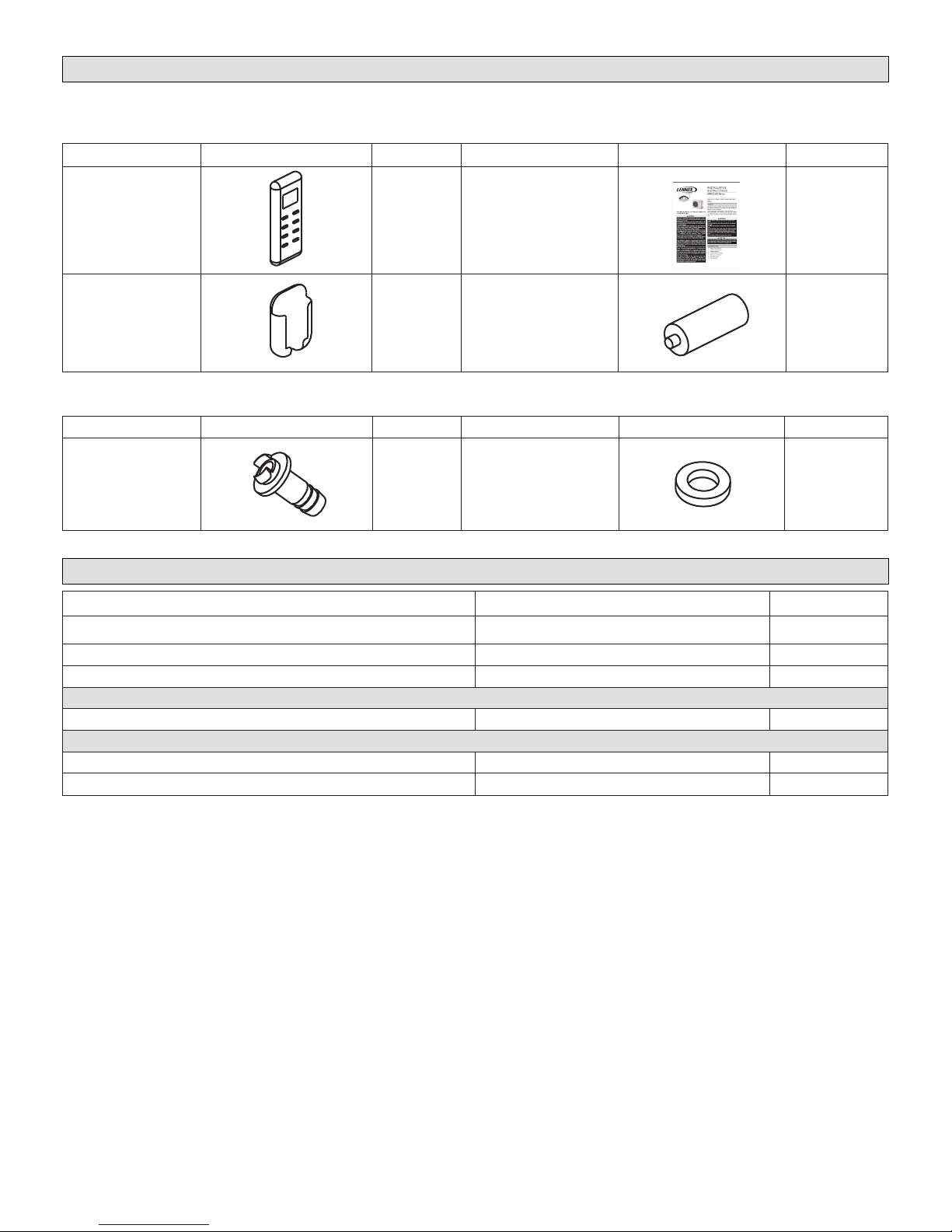
Included Parts
Package 1 of 1 contains the following:
1 - Assembled Indoor Unit
Parts Figure Quantity Parts Figure Quantity
M0STAT60Q-1
Wireless controller
Wireless control
holder with 2 mounting
screws
1
1 Batteries (AAA) 2
Installation and owner’s
manual
1 ea.
The assembled indoor unit will include the following items:
1 - Assembled Outdoor Unit and the following items:
Parts Figure Quantity Parts Figure Quantity
Drain connector 1 Seal ring 1
Indoor / Outdoor Unit Match-Ups
Outdoor Unit Indoor Unit Voltage
MPA024S4S-*P or MPB024S4S-*P MCFA024S4-*P
MPA036S4S-*P or MPB036S4S-*P MCFA036S4-*P
MPA048S4S-*P or MPB048S4S-*P MCFA048S4-*P
208/230V
208/230V
208/230V
MPB018S4S-*P MCFB018S4-2P
MLA018S4S-*P MCFB018S4-2P
MLA024S4S-*P MCFA024S4-2P
208/230V
208/230V
208/230V
2
Page 3
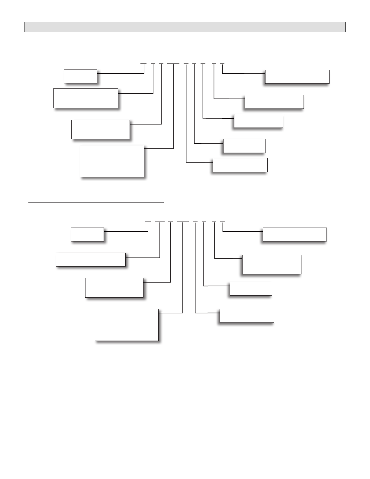
Model Number Identication
OUTDOOR SINGLE ZONE HEAT PUMP UNITS
M P A 009 S 4 S - 1 P
Series Type
M = Mini-Split
Unit Type
L = Low Ambient Heat Pump
P = Heat Pump
Major Design Sequence
A = 1st Generation
B = 2nd Generation
Nominal Cooling Capacity
018 = 1.5 tons
024 = 2 tons
036 = 3 tons
048 = 4 tons
CEILING/FLOOR NON-DUCTED INDOOR UNITS
M CF A 018 S 4 - 1 P
Series Type
M = Mini-Split
Voltage
P = 208/230V-1 phase-60hz
Minor Design Sequence
1 = 1st Revision
Refrigerant Circuits
S = Single Circuit
Refrigerant Type
4 = HFC-410A
Cooling Efciency
S = Standard Efciency
Voltage
P = 208/230V-1 phase-60hz
Unit Type
CF = Ceiling/Floor Non-Ducted
Major Design Sequence
A = 1st Generation
B = 2nd Generation
Nominal Cooling Capacity
018 = 1.5 tons
024 = 2 tons
036 = 3 tons
048 = 4 tons
Minor Design Sequence
1 = 1st Revision
2 = 2nd Revision
Refrigerant Type
4 = HFC-410A
Cooling Efciency
S = Standard Efciency
3
Page 4
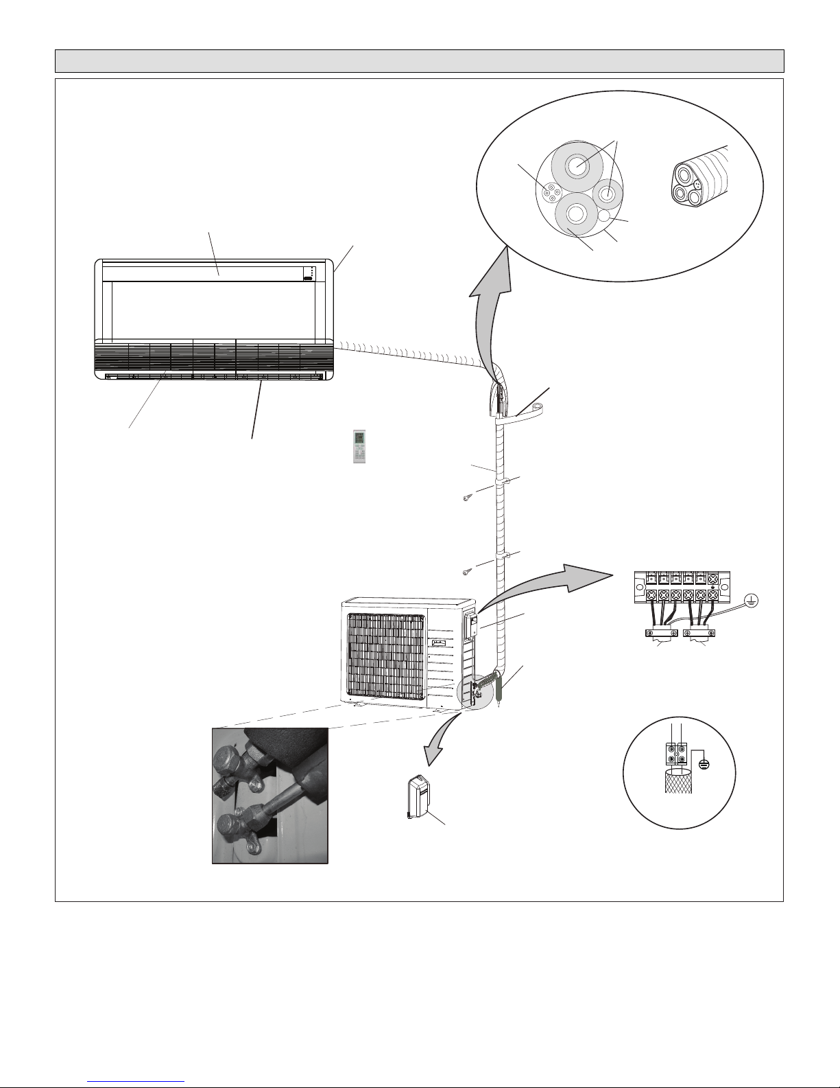
Typical Single-Zone System Components
IMPORTANT - Condensate drain line must always
be located at the bottom of the
bundle.)
Wiring
Line set
(wrapped in foam insulation)
Supply Air
Indoor unit wiring connections
Condensate drain line
(wrapped in foam insulation)
Refrigerant Line Set, Condensate Line
And Indoor / Outdoor Cable
Filter
Indoor Unit
Return Air
Wireless Remote
Control
Utility
Bundle
UV-rated tape (field-provided)
IMPORTANT - The refrigerant
metering device for this system is
located in the outdoor unit. This
makes it necessary to insulate the
Communication cable
036 and 048 only
Tape
(field-provided)
refrigerant lines individually to
prevent sweating.
Outdoor Unit
012-036 shown
208/230V Outdoor Unit
Terminal Block
1 2 3 L1 L2
Liquid and vapor shut off valves
Figure 1. Typical System Shown
4
Access cover
for valves
Condensate drain
from Indoor Unit
To Indoor
Unit
Communication Cable
036 and 048 only
TO INDOOR COMM. BUS
NOTE:
LLEY WO
ARG Y
S1
XT2
Use 2-conductor
shielded wire
S2
To Power
Supply
Page 5
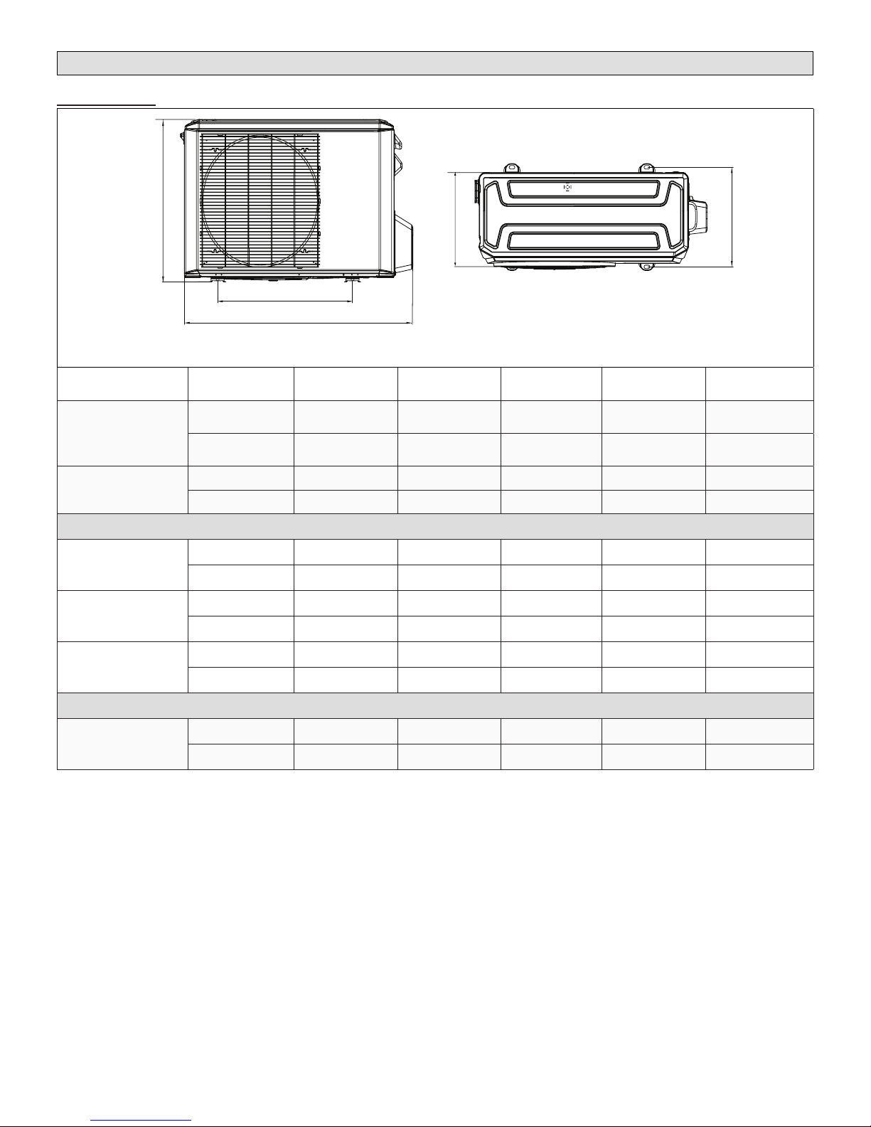
System Dimensions
A
E
D
B
C
TYPICAL APPEARANCE OF UNITS
Outdoor Units
Model
MPA024S4S-*P
MPA036S4S-*P
MPA048S4S-*P
MPB018S4S-*P
MPB024S4S-*P
MPB036S4S-*P
MPB048S4S-*P
MLA024S4S-*P
Unit of
Measurement
inches 40-5/8 25-1/4 31-7/8 15-1/8 16
mm 1032 641 810 384 406
inches 40-1/4 25 53-3/4 15-3/8 16
mm 1023 635 1365 391 406
inches 36 21-1/4 27-5/8 14-1/4 13-3/4
mm 914 540 702 363 350
inches 40-1/2 26-1/2 31-7/8 16-1/8 15-7/8
mm 1032 673 810 410 403
inches 41-1/8 25 52-1/2 16-1/8 15-7/8
mm 1045 634 1333 415 404
inches 40-3/4 26-1/2 31-7/8 15-1/8 16
mm 1035 673 810 384 406
A B C D E
Figure 2. Outdoor Unit Dimensions - Inches (mm)
5
Page 6
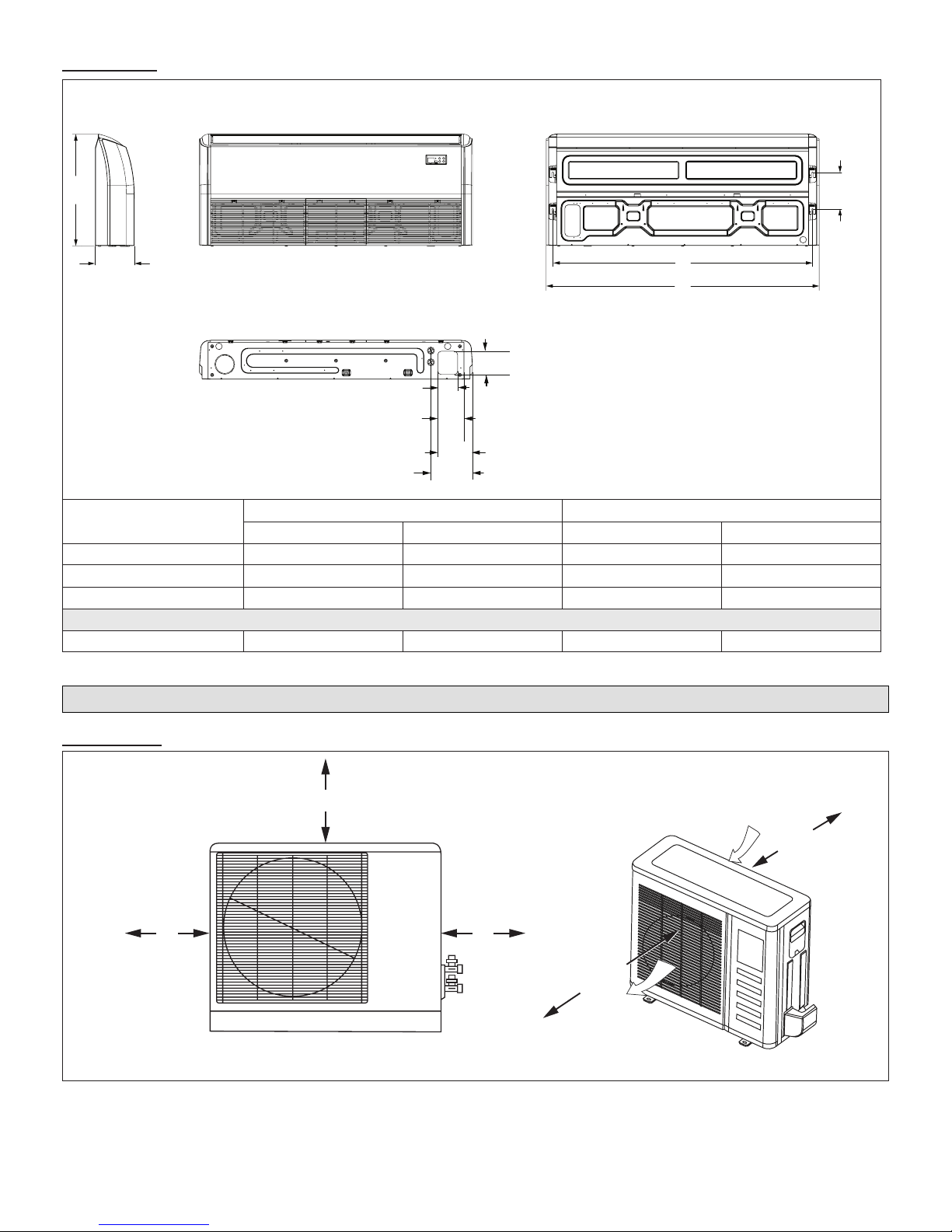
Indoor Units
4
(222)
26-5/8
(676)
9-1/4
(235)
SIDE VIEW
FRONT VIEW
5-1/2
(139)
B
A
BACK VIEW
4-3/4
BOTTOM VIEW
(120)
6
(152)
8
9-1/2
(203)
(241)
Model No.
in. mm in. mm
A B
MCFA024S4S-*P 42-1/8 1070 39 991
MCFA036S4S-*P 50-5/8 1286 47-3/8 1203
MCFA048S4S-*P 65 1651 61-3/4 1568
8-3/
MCFB018S4S-*P 42-1/8 1070 39 991
Figure 3. MCFA and MCFB Indoor Unit Dimensions - Inches (mm)
System Clearances
Outdoor Unit
24 (610)
12
(305)
1
Minimum rear clearance can be 6 inches (152 mm) when mounted on brackets
and with no obstructions on the other three sides.
24
(610)
79
(2007)
Air Outlet
Air Inlet
1
12
(305)
Figure 4. Outdoor Unit Clearances - Inches (mm)
6
Page 7
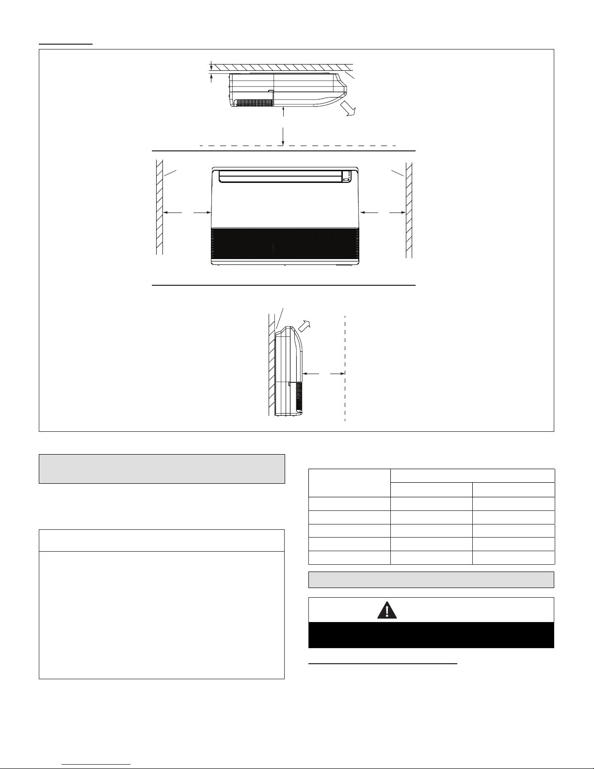
Indoor Unit
CEILING APPLICATIONS
3/4
(19)
SIDE VIEW
59 (1499)
(Service Clearance
DROP CEILING
SUPPLY
AIR
WALL WALL
24
(610)
CEILING AND FLOOR APPLICATIONS
FLOOR APPLICATIONS
FRONT VIEW
Unit Flush with Wall
SUPPLY
AIR
59 (1499)
(Service Clearance
Front of Unit)
24
(610)
Figure 5. Indoor Unit Clearances - Inches (mm)
Torque Requirements for Caps and
Fasteners
When servicing or repairing HVAC components, ensure
the fasteners are appropriately tightened. “Table 1. Torque
Requirements” provides torque values for fasteners.
IMPORTANT
Only use Allen wrenches of sufcient hardness (50Rc -
Rockwell scale minimum). Fully insert the wrench into
the valve stem recess.
Service valve stems are factory-torqued from 9 ft.-lbs.
(12 N) for small valves, to 25 ft.-lbs. (34 N) for large
valves) to prevent refrigerant loss during shipping and
handling. Using an Allen wrench rated at less than 50Rc
risks rounding or breaking off the wrench, or stripping
the valve stem recess.
See the Lennox Service and Application Notes C-08-1
for further details and information.
Table 1. Torque Requirements
Parts
Service valve cap 8 ft.-lb. 11
Sheet metal screws 16 in.-lb. 2
Machine screws #10 27 in.-lb. 3
Compressor bolts 7 ft.-lb. 10
Gauge port seal cap 8 ft.-lb. 11
Recommended Torque
U.S. Newton-Meter- N
Indoor Unit Installation
CAUTION
In order to avoid injury, take proper precaution when
lifting heavy objects.
Unit Placement Considerations
AVOID
Do not install the unit in the following locations:
• Areas exposed to petrochemicals or petrochemical
products
7
Page 8
• Areas exposed to salt or other corrosive materials or
Electrical
Connections
Refrigerant / Drain
Pipe Connections
caustic gases
• Areas exposed to extreme voltage variations (such as
factories
• Tightly enclosed areas that may impede service of the
unit
• Areas exposed to fossil fuels (such as oil or gas in
kitchens)
• Areas exposed to strong electromagnetic forces
• Areas exposed to acids or alkaline detergents
DO
• Place the unit so that it is not exposed to direct sunlight
• Ensure the structural ceiling can support the weight of
the unit
• Select a location where condensate line will have the
shortest run to a suitable drain per local codes.
• Allow sufcient space around unit for proper operation
and maintenance
• Install unit a minimum of 3 feet (1m) away from any
antenna, power cord (line) radio, telephone, security
system, or intercom. Electrical interference and radio
frequencies from any of these sources may affect operation
• Be sure to instruct customers how to properly operate
the unit (especially maintenance of air lter, and operation procedure) by having them carry out operations
themselves while looking at the manual provided with
the controller
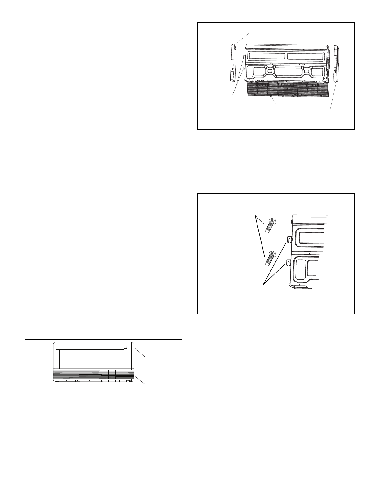
Side Panel
Factory Installed
Hanging Brackets
Grille
Side Panel
Figure 7. Remove Side Panel and Grille
2. Install four mounting bolts (appropriate for your
application) to the wall. See “Figure 3. MCFA and
MCFB Indoor Unit Dimensions - Inches (mm)” on
page 6 to ensure proper positioning of the bolts.
3. Upon conrming the four bolts are level, correctly
spaced and secured to the wall; lift the unit onto the
brackets. Conrm the unit is level before continuing.
Field-Installed
Mounting Bolts
Floor Installation
• Locate a suitable position within the space where
maintenance access and supply air will not be restricted or affected by obstacles. See “Figure 5. Indoor Unit
Clearances - Inches (mm)” on page 7 for minimum
clearances
• Place the MCFA or MCFB on a wall which is both ca-
pable of supporting the unit’s weight and which is con-
structed to enable the unit to t ush on the wall. An
uneven wall may lead to vibration and subsequent unit
damage
Figure 6. Floor / Wall Applications
Units are wall mounted using factory-installed hanging
brackets.
1. Remove the side panels and grille to expose factoryinstalled hanging brackets on the sides of the unit.
Factory Installed
Hanging Brackets
Figure 8. Hang Unit on Mounting Bolts
Ceiling Installation
• Locate a suitable position within the space where
maintenance access and supply air will not be restricted or affected by obstacles
• Suspend the unit from a ceiling which is capable of
supporting the unit’s weight
Units are suspended from the ceiling using factory-
installed hanging brackets.
1. Remove the side panels and grille to expose factoryinstalled hanging brackets on the sides of the unit
8
Page 9

Grille
Side Panel
Threaded
T
8. Hang the unit by sliding the factory-installed hanging
DRAIN LINE
Slope at least 1/4”
per foot (18 mm per M)
3 ft. (1 m)
SUPPORT
STRAPS
brackets on to the threaded rods between the sets of
washers and nuts.
9. Use the leveling nut (beneath hanging brackets)
to adjust the unit to the correct height. Remove the
electrical tape holding the upper washers and nuts
in place and tighten each of the four nuts above the
brackets down onto the brackets. This will ensure that
the unit remains level.
Indoor Unit Condensate Piping Connections
Figure 9. Remove Side Panel and Grille
2. Install suspension rods in the structural
ceiling or concrete slab in a suitable location.
If the structural ceiling is constructed of concrete,
install anchors to accept four suitably sized threaded
rods to suspend the indoor unit. If the structural ceiling
includes wooden joists, use angle iron or Unistrut
channel xed securely in place to accept the threaded
rods.
3. Slide one nut and one washer onto each threaded rod.
Rod
CONCRETE CEILING
USING ANCHORS
Anchor
Angle Iron Bolted
in Place Across
Wooden Joists
Threaded
Rod
ANGLE IRON
ACROSS WOODEN
JOISTS
Wooden
Joist
Figure 10. Locate Threaded Rods
4. Use electrical tape to keep the washer from falling off.
Position the nuts
5. Slide a second washer and then a second nut onto
each rod slightly above the nal resting place of the
hanging brackets.
6. If necessary, install a eld-provided isolation grommet
to prevent transmission of vibration from unit to
structural ceiling.
hreaded Rod
IMPORTANT
Make sure that drain piping is properly routed and
insulated to prevent both leaks and condensation.
1. Use a eld-provided hose clamp to secure the drain
line stub on the side of the cassette base to a eld-
supplied 1” (25 mm) drain line.
NOTE: Take care not to over-tighten the hose clamp as
this may damage the drain line stub.
NOTE: Connection between stub and drain line must be
watertight. Apply non hardening plumbing joint
compound if needed to ensure a watertight seal.
2. Conrm proper slope (not less than 1/4 inch per foot
(18 mm per m)) and routing of condensate lines to
ensure moisture is drained away from the indoor unit.
3. Drain should be as short as possible and should
not have any droops or kinks that would restrict
condensate ow and shall be approved resistant pipe.
There must be a 2-inch (51 mm) space between
the end of the condensate drain and the nal
termination point (ground, open drain, etc.) to
ensure that the line will drain freely.
4. After the system installation is complete, the
condensate drain line must be checked for leaks and
proper drainage. If a eld-provided condensate pump
has been installed, it must be checked to ensure proper
operation. This check is part of the start-up process
which must be done by the installing contractor.
IMPORTANT
Drain should have a slope of at least ¼ inch per foot and
should be approved corrosion-resistant pipe. You must
conrm operation of every drain and pump in the system
as part of the commissioning procedure.
Field-Provided
Isolation
Grommet
Washer
Leveling
Nut
Figure 11. Locate Bracket on Threaded Rod
7. Use either a mechanical lifting device or a minimum of
two people to raise the unit.
Suspension
Bracket
Figure 12. Indoor Unit Suspended from Ceiling
using a Properly Sloped Gravity Drain
9
Page 10

Outdoor Unit Installation
Placement Considerations
CAUTION
In order to avoid injury, take proper precaution when
lifting heavy objects.
Consider the following when positioning the unit:
• In coastal areas or other places with salty atmosphere
of sulfate gas, corrosion may shorten the life of the
unit. In coastal areas, the coil should be cleaned with
potable water several times per year to avoid corrosive
buildup (salt)
• Some localities are adopting sound ordinances based
on the unit’s sound level registered from the adjacent
property, not from the property where the unit is installed. Install the unit as far as possible from the property line
• When possible, do not install the unit directly outside
a window. Glass has a very high level of sound transmission
• Install unit level
Building Structure
Ground
Level
Figure 13. Install Unit Level
• Since water drains from the outdoor unit during various stages of operation, do not place anything which
may be damaged by moisture under the unit
Direct Sunlight, Rain, Snow and Ice Protection
• If the outdoor unit is subjected to prolong exposure to
direct sunlight with temperatures over 100°F (38°C) a
canopy is recommended as illustrated in “Figure 14.
Outdoor Unit on Pedestal (Stand) and Protective Canopy” or “Figure 19. Dog House-Style Shelter” on page
11.
IMPORTANT
The construction of a canopy or shade is necessary
because of an ambient limit control set to 122°F (50°C)
to protect the electronics. If the outdoor unit is placed in
direct sunlight it is possible that the limit may activate
and shut down the unit.
• Place unit away from overhanging roof lines which
would allow water or ice to drop on, or in front of, coil
or into unit. Construct a canopy as illustrated in “Figure
14. Outdoor Unit on Pedestal (Stand) and Protective
Canopy”
• The unit base should be elevated above the depth of
average snows as illustrated in “Figure 15. Outdoor
Unit on Brackets above Snow Line”
• In heavy snow areas, do not place the unit where drift-
ing will occur as illustrated in “Figure 16. Outdoor Unit
Air Flow Obstructed by Snow” on page 11
• Carefully consider how to manage defrost water disposal to prevent ice from blocking walkways or creating a safety hazard near the outdoor unit as illustrated in “Figure 17. Avoid Defrost Water Ice Hazard” on
page 11
Protective canopy
Protective canopy
• Choose a place solid enough to bear the weight and
vibration of the unit, where the operation noise will not
be amplied
• Choose a location where the hot air discharged from
the unit or the operation noise will not be a nuisance
to neighbors
• Avoid installing the outdoor unit near a bedroom or
other places where noise may cause a problem
• There must be sufcient space to carry the unit into
and out of the site
• There must be unobstructed air ow around the air inlet and the air outlet
• The unit must not be installed in areas where a ammable gas leak may occur
• Install the outdoor unit a minimum of 3 feet (1m) away
from any antenna, power cord (line), radio, telephone,
security system, or intercom. Electrical interference
and radio frequencies from any of these sources may
affect operation
24 in
610 mm
12 in
305 mm
Air Inlet
Air Outlet
Pedestal
(stand)
Side View
Front View
Figure 14. Outdoor Unit on Pedestal (Stand) and
Protective Canopy
10
Pedestal
(stand)
Page 11

Air Inlet
Air Outlet
Air Outlet
Air Inlet
12 in
305 mm
79 in
2007 mm
mm) from the unit as illustrated in “Figure 18. Wind
Barrier”
• When prevailing wind is into the discharge side, then
position the wind barrier a minimum 79 inches (2007
mm) from the front of the unit as illustrated in “Figure
18. Wind Barrier”
• Outdoor unit can be installed in a dog house style
shelter as illustrated in “Figure 19. Dog House-Style
Shelter”
• a roof overhang as illustrated in “Figure 20. Unit installed in Alcove”
Prevailing Winter Winds from Air Inlet Side
Figure 15. Outdoor Unit on Brackets above Snow
Line
Figure 16. Outdoor Unit Air Flow Obstructed by
Snow
Wind Barrier
Inlet Air
Discharge Air
Wind Barrier
Prevailing Winter Winds From Air Discharge Side
Figure 18. Wind Barrier
24 in
12 in
305 mm
610 mm
24 in
610 mm
12” (305mm)
Min. Distance
79” (2007mm)
Min. Distance
12 in
305 mm
Figure 17. Avoid Defrost Water Ice Hazard
Prevailing Winds
Normally wind bafes are not required for a outdoor unit.
However, in order to maximize reliability and performance,
the following best practices should be followed.
If unit coil cannot be installed away from prevailing winter
winds, some method of protecting the coil is recommended.
However, minimum clearances as reference in “Figure 4.
Outdoor Unit Clearances - Inches (mm)” on page 6
must be observed at all times.
Common application examples are:
• When prevailing winds are from the air inlet side, then
position the wind barrier a minimum of 12 inches (305
NOTE - Minimum clearances shown.
Figure 19. Dog House-Style Shelter
11
Page 12

12 in
305 mm
24 in
610 mm
12 in
305 mm
24 in
610 mm
NOTE - Minimum clearances shown.
Figure 20. Unit installed in Alcove
Four Field-provided Anchor Bolts
Buried Refrigerant Pipe Protection
• All refrigerant lines must be insulated regardless of if
it is buried
• In addition to insulating each line of piping, buried lines
must rest inside a sealed, watertight conduit
• The conduit must be designed so it cannot collect and
retain water
Outdoor Unit Condensate Piping
Condensate formed during the heating and defrost
processes must be drained from heat pump units. Drain
holes are provided in the base of the units to ensure proper
drainage. Heat pumps must be raised when installed on a
concrete pad or the ground to allow drainage to occur. If
the heat pump unit is installed on wall mounting bracket,
insert the provided drain connector into one of the 1
inch (25 mm) drain holes and attached a eld-provided
insulated drain hose to the connector. Use eld-provided
rubber plugs to cover any unused drain holes.
CAUTION
Roof Damage!
This system contains both refrigerant and oil. Some
rubber roong material may absorb oil. This will cause
the rubber to swell when it comes into contact with oil.
The rubber will then bubble and could cause leaks.
Protect the roof surface to avoid exposure to refrigerant
and oil during service and installation. Failure to follow
this notice could result in damage to roof surface.
Securing Outdoor Unit to Slab, Frame, or Rails
If the outdoor unit is installed on a eld-provided slab or
frame, use lag bolts or equivalent to secure the outdoor
unit to the slab or frame.
Figure 22. Securing Outdoor Unit to Slab
Four Field-Provided
Anchor Bolts
Figure 23. Securing Outdoor Unit to Rails
Securing Outdoor Unit To Hanging Brackets
If the outdoor unit is installed on eld-provided wall
mounting brackets, use lag bolts or equivalent to secure
the outdoor unit to the bracket. Minimum rear clearance
can be reduced to 6 inches (152 mm) when mounted
on brackets and with no obstructions on the other three
sides. Allow for condensate disposal when placing units
above one another.
Drain
Connector
Chassis
Condensate Drain
(location varies per model)
Figure 21. Condensate Drain
Securing the Outdoor Unit
Install the unit a minimum of 4 inches (102 mm) above the
Slab or Roof Mounting
roof or ground surface to avoid ice build-up around the
unit. Place the unit above a load bearing wall or area of
the roof that can adequately support the unit. Consult local
codes for rooftop applications.
12
6 in
152 mm
Air Inlet
Air Outlet
Figure 24. Securing Outdoor Unit to Brackets
Page 13

Refrigerant Piping Connections
Field piping consists of two copper lines connecting the
outdoor unit to the indoor unit. “Table 2. Refrigerant Piping
and Indoor Unit Connection Sizes” lists the connection
sizes. The connections are made using the provided brass
are nuts at the end of the refrigerant piping connections.
Both lines must be individually insulated.
1. The seal on the unit refrigerant piping connections
should remain in place until the last possible moment.
This will prevent dust or water from getting into the
refrigerant piping before it is connected.
2. CAREFULLY adjust refrigerant piping connections to
suit the application.
3. Slowly loosen one of the are nuts to release the
factory nitrogen charge from the indoor units only.
4. Remove the are nuts from the connections on the
unit and discard the seal from each of the piping
connections.
5. Slide the are nuts onto the ends of the eld-provided
refrigerant piping before using a suitable aring tool to
are the end of the copper pipe.
6. Apply recommended HFC-410A refrigerant lubricant
to the outside of the ared refrigerant lines.
A
B
TO INDOOR
CANT ON THE OUTSIDE OF
THE FLARE
Figure 25. Making Connections
(Male to Female Connection)
TORQUE WRENCH
UNIT
TO OUTDOOR UNIT
Figure 26. Tighten Flare Nut
MALE FLARE
CONNECTION
BACKUP
WRENCH
IMPORTANT
The compressor in this unit contains PVE
oil (Polyvinylether). PVE oil is formulated for
hydro-uorocarbon (HFC) refrigerants, such as HFC-
410A, which this system contains. While it may have
some miscibility properties with mineral-based oil and
POE oil (Polyolester), it is not recommended to mix PVE
oil with any other type of refrigerant oil.
7. Align the threaded connections with the
ared refrigerant lines. Tighten the are nuts
lightly at rst to obtain a smooth match as
illustrated in “Figure 25. Making Connections
(Male to Female Connection)”.
8. Once snug, continue another half-turn on each nut
which should create a leak-free joint. A torque wrench
may be used to tighten are nuts using “Table 3. Flare
Nut Torque Recommendations”. Do not over-tighten
a ared joint. Flared connections should always
be accessible and must be insulated to prevent
condensation.
9. After refrigerant piping has been installed and checked
for leaks, apply insulation over all ared connections.
Table 2. Refrigerant Piping and Indoor Unit
Connection Sizes
Size
(Btuh)
18000 1/4 1/2
24000, 36000 &
48000
Liquid Line
in.
3/8 5/8
Gas Line
in.
Table 3. Flare Nut Torque Recommendations
Outside
Diameter
Inches
1/4 15 ft.-lb. (20 N) 1/4 turn
3/8 26 ft.-lb. (35 N) 1/2 turn
1/2 41 ft.-lb. (56 N) 7/8 turn
5/8 48 ft.-lb. (65 N) 1 full turn
Recommended
Torque
No torque wrench available
Finger tighten and use an
appropriately sized wrench to
turn an additional:
13
Page 14

Table 4. Refrigerant Line Set Requirements
OUTDOOR UNIT
OUTDOOR UNIT
INDOOR UNIT
INDOOR UNIT
Maximum Line Set
Length
Maximum Line Set
Length
Maximum
Elevation -
Outdooor
Unit BELOW
Indoor Unit
Maximum
Elevation -
Outdooor
Unit ABOVE
Indoor Unit
Minimum Line Set
Length - 10 ft. (3m)
Minimum Line Set
Length - 10 ft. (3m)
Outside Unit BELOW Indoor Unit Outside Unit ABOVE Indoor Unit
Do not allow for excess length of line sets to be left rolled up as part of the
required distance, or in general. This will also cause additional performance issues.
IMPORTANT
Each system size has a line set length and vertical elevation parameters.
Line Set Diameters (in.)
System Size (KBtu)
Liquid Gas
024 3/8 5/8 82 ft. (25 m) 82 ft. (25 m) 164 ft. (50 m)
036/048 3/8 5/8 98 ft. (30 m) 98 ft. (30 m) 213 ft. (65 m)
Maximum Elevation
Outdoor Unit BELOW
Indoor Unit - Feet
(Meter)
Maximum Elevation
Outdoor Unit ABOVE
Indoor Unit - Feet
(Meter)
Set Length - Feet
Maximum Line
(Meters)
Leak Test and Evacuation
Air and moisture remaining in the refrigerant system will
have undesirable effects as indicated below:
• Pressure in the system rises
• Operating current rises
• Cooling or heating efciency drops
• Moisture in the refrigerant circuit may freeze
• Water may lead to corrosion of parts in the refrigeration system
• Relieve the nitrogen pressure by: loosening the
charge hose connector at the nitrogen cylinder
• When the system pressure is reduced to normal,
disconnect the hose from the cylinder
Table 5. Pressure Test Specications
Bar Psig kPa Duration
1 3 44 303 Minimum of 10 minutes
2 15 220 1517 Minimum of 10 minutes
3 32 470 3241 Minimum of 10 minutes
4 45 650 4482
The line set between the indoor and outdoor units
must be leak tested and evacuated to remove any noncondensables and moisture from the system.
5 32 470 3241
Leak Test
Use the following procedure to test for system leaks:
1. Connect the manifold gauge set and dry nitrogen gas
cylinder to the liquid and gas service ports.
2. Open valve on nitrogen cylinder.
3. Pressurize the system per the pressure test
specications in “Table 5. Pressure Test Specications”.
4. Check that the system pressure remains stable. If
there is any movement check system for leaks.
5. After the system is found to be free of leaks:
• Close valve on nitrogen cylinder
Use only oxygen-free nitrogen (OFN).
Triple Evacuation Procedure
A Micron or Torr gauge must be used for this procedure.
1. Discharge the oxygen-free nitrogen and evacuate the
system to a reading of 8000 Microns (8 Torr) using all
service valves.
2. Break the vacuum by allowing nitrogen into the port
connections (liquid and gas line pipes) until a positive
pressure is achieved.
3. Evacuate the system to a reading of 5000 Microns (5
14
1 hour. Stress test to prove the
integrity of the complete installation.
24 hours. Lower system pressure
test, after conrmation No. 4 was
successfully completed.
IMPORTANT
Page 15

Torr).
4. Break the vacuum by allowing nitrogen into the port
connections (liquid and gas line pipes) until a positive
pressure is achieved
5. Evacuate the system to a minimum reading of 500
Microns (0.5 Torr).
6. For a moisture-free system, ensure the vacuum is held
without movement for a minimum of 4 hours.
7. If vacuum fails to hold, carry out steps 2 through 6 until
vacuum holds.
Wiring Connections
WARNING
Electric Shock Hazard. Can cause injury or death. Unit
must be rounded in accordance with national and local
codes.
Line voltage is present at all components when unit is
not in operation. Disconnect all remote electric power
supplies before opening access panel. Unit may have
multiple power sources.
IMPORTANT
This unit must be properly grounded and protected by a
circuit breaker. The ground wire for the unit must not be
connected to a gas or water pipe, a lightning conductor
or a telephone ground wire.
Do not connect power wires to the outdoor unit until
all other wiring and piping connections have been
completed.
Do not install the unit near a lighting appliance that
includes a ballast. The ballast may affect remote control
operation.
IMPORTANT
Install unit so that unit disconnect is accessible.
Use specied wiring and cable to make electrical
connections. Clamp cables securely and make sure that
connections are tight to avoid strain on wiring. Insecure
wiring connections may result in equipment failure and
risk of re.
Wiring must be installed so that all cover plates can be
securely closed.
CAUTION
All terminal connections must be made as illustrated
in the following diagrams. Improperly connected wiring
could damage unit or cause communication errors
between indoor and outdoor units.
In the U.S.A., wiring must conform with current local codes
and the current National Electric Code (NEC). In Canada,
wiring must conform with current local codes and the
current Canadian Electrical Code (CEC).
Outdoor Unit
• Refer to unit nameplate for minimum circuit ampacity
and maximum over-current protection size
• Make all electrical power wiring connections at the outdoor unit
• Be sure to reattach all electrical box covers after connections are complete
Indoor Unit
• All indoor units are powered by the outdoor unit.
• Communication Wiring (Indoor Units 30K and Below):
Use one stranded 4-conductor wire to provide power
and communication
• Communication Wiring (Indoor Units 36K and Above):
Use one stranded 3-conductor wire to provide power
and one stranded 2-conductor wire to provide communication
• Use minimum of 18 GA stranded wiring
• When installing a condensate pump, wire in-line with
the CN5 oat switch
15
Page 16

IMPORTANT
208/230V Outdoor Unit
Terminal Block
From Power
Supply
1 2 3 L1 L2
Terminal Block
1 2 3
208/230V Indoor Unit
Outdoor Unit Indoor Unit
From Power
Supply
Indoor Unit
CommunicationTerminal Block
L1 L2
Power Terminal Block
208/230V Outdoor Unit
L1 L2
L1 L2
Power Terminal Block
208/230V Outdoor Unit
Power Terminal Block
208/230V Indoor Unit
S1 S2
Communication Terminal Block
Outdoor Unit
E Y XYQS1E P
S2
Outdoor Unit
Indoor Unit
All diagrams (Figure 29 through Figure 39) are typical wiring diagrams. Refer to the wiring diagram on the unit for actual
wiring.
Figure 27. Single-Zone Wiring 30K and Below
Figure 28. Single-Zone Wiring 36K and Above
16
Page 17

0
8
4
1
2
3
5
6
7
C
9
A
B
D
E
F
1
2
ON
0
8
4
1
2
3
5
6
7
C
9
A
B
D
E
F
1
2
ON
0
8
4
1
2
3
5
6
7
C
9
A
B
D
E
F
1
2
ON
0
8
4
1
2
3
5
6
7
C
9
A
B
D
E
F
1
2
ON
S1+S 2
0~F 0~F 0~F 0~F
ADDRESS
CODE
0~15
16~31
32~47
48~63
FOR
CCM UNIT ADDR ESS
DC MOTOR
DRIVER MODULE
CN13
CN3
3
CN1 5
5
M
CN6
T2
T1
4
INDO OR COIL TEMP. SENS OR
ROOM TEMP. SENSOR
BLACK
WHITE
INDOOR UNIT MAINBOARD
CN3
RED
CN2
C N1
Y/G
BLACK
CN41
YELLOW
CN5
WATER LEVE L SWITCH
Inductor
CN8
CN18
RED
RED
1
ON
1
ON
COOLING
PRIORITY
HEATING
PRIORITY
FACTORY
SETTING
MODE
CN19
BLUE
BLACK
To LVM
Comm.Bus
WHITE
X Y E
Y/G
1
23
FILTER-BOARD
BLACK
RED
•••••••••••••••••••••• ••••••••
1
ON
1
ON
SW2
1
2
ON
1
2
ON
1
2
ON
1
2
ON
SW6
CODE
FOR TEMP. COMP ENSATION(HEATING)
FACTORY
SETTING
EEPROM
default
1
2
ON
1
2
ON
1
2
ON
1
2
ON
SW1
TEL0
EEPROM
default
FACTORY
SETTING
FOR ANTI-COLD WIND
1
ON
1
ON
FACTORY
SETTING
FOR SETTING AUTO-R ESTART
SW3
MODE
AUTO-RESTART
NOT AUTO-RESTART
CN2 3
ON/O FF
CN33
ALARM
Alarm
Output
Remote
Control
Ceiling-Floor Type
CN21
M
5
5
VSWING(INACTIVE)
CN24
M
5
SWING
FAN
FOR MODE CONFLICT SETTING
DISPLAY
BOARD
10
CN10A
TO WIRED
CONTROLLER
2
CN40
TO
PROGRA MMABL E
WIRED
CONTRO LLE R
4
2
•••••
COMPONENT IN DASH
LINE IS OPTIONAL
OR FIELD WIRING.
Note: The
programmable
wired controller
and regular
wired controller
use the same
wiring connector
(VRF only)
(VRF only)
32˚F (0˚C)36˚F (2˚C)39˚F (4˚C)
75˚F (24˚C) 59˚F (15˚C) 46˚F (8˚C )
Figure 29. MCFB018S4-*P Unit Wiring Diagram
M
FAN
C o m m .B u s
3
C N 3
DC MOTOR
DRIVER MODULE
To L V M
• • • • •
COMPONENT IN DASH
LINE IS OPTIONAL
OR FIELD WIRING.
Note: The
programmable
wired controller
and regular
wired controller
use the same
wiring connector
X Y E
INDOOR UNIT MAINBOARD
5
C N 13
WHITE
BLUE
BLACK
CN2 3
ON/O FF
Remote
Control
Figure 30. MCFA024S4-*P Unit Wiring Diagram
CN1 5
C N 19
Ceiling-Floor Type
CN3 3
ALA R M
Alarm
Output
CN8
CN18
CN21
CN24
CN40
CN10A
CN3
C N 1
C N 2
C N 41
R ED
B L A C K
FILTER-BOARD
17
RED
RED
5
5
M
VSWING(INACTIVE)
2
10
DISPLA Y
BOARD
CN6
4
BLACK
Y/G
YELLOW
BLACK
WHITE
WA TE R L EV EL SW IT C H
RED
CN5
In d uc to r
5
5
SWING
4
PROGRAMMABLE
2
CONTROLLER
5
TO WI RED
CONTRO LLER
INDO OR C OIL T EMP. SENS OR
ROOM TEMP. SENSOR
2 3
1
M
M
TO
WIRED
Y/G
T2
T1
Page 18

CN5
In d uc to r
CN8
CN18
CN7
T2B
OUTER PIPE TEMP. SENSOR
T2
T1
CN6
4
BLACK
WHITE
RED
RED
VSWING(INACTIVE)
CN21
CN24
M
M
M
5
5
5
5
SWING
INDOOR UNIT MAINBOARD
DC MOTOR
DRIVER MODULE
CN1 3
CN3
M
3
C N 15
5
FAN1
Ceiling-Floor Type
CN2 3
ON/O FF
CN3 3
ALA RM
Alarm
Output
Remote
Control
CN19 CN16
BL U E
BL A C K
YE L L OW
G RA Y
To LVM
Comm.Bus
To outdoor
Comm.Bus
W H IT E
S1
S2
X Y
(
E
)
Y/G
C N 3
C N 2
C N 1
BLACK
RED
Ferr it e b ea d
FILTER-BOARD
L1
L 2
R ED
BL A C K
Y/G
Y/G
Y/G
• • • • •
COMPONENT IN DASH
LINE IS OPTIONAL
OR FIELD WIRING.
INDO OR C OIL T EMP. SENS OR
ROOM TEMP. SENSOR
FAN
WA TE R L EV EL SW IT CH
DISPLA Y
BOARD
10
CN10A
TO WI RED
CONTRO LLER
5
TO PROGRAMMABLE
WIRED CONTROLLER
2
CN40
4
2
Note: The
programmable
wired controller
and regular
wired controller
use the same
wiring connector
Figure 31. MCFA036S4-*P Unit Wiring Diagram
CN5
In d uc to r
CN8
CN18
CN7
T2B
OUTER PIPE TEMP. SENSOR
T2
T1
CN6
4
BLACK
WHITE
RED
RED
VSWING(INACTIVE)
CN21
CN24
M
M
M
5
5
5
5
SWING
INDOOR UNIT MAINBOARD
DC MOTOR
DRIVER MODULE
CN1 3
CN3
M
3
C N 15
5
FAN1
Ceiling-Floor Type
CN2 3
ON/O FF
CN3 3
ALA R M
Alarm
Output
Remote
Control
CN19 CN16
BL U E
BL A C K
YE L L OW
G RA Y
To LVM
Comm.Bus
To outdoor
Comm.Bus
W H IT E
S1
S2
X Y
(
E
)
Y/G
C N 3
C N 2
C N 1
BLACK
RED
Ferr ite b ea d
FILTER-BOARD
L1
L 2
R ED
BL A C K
Y/G
Y/G
Y/G
• • • • •
COMPONENT IN DASH
LINE IS OPTIONAL
OR FIELD WIRING.
INDO OR C OIL T EMP. SENS OR
ROOM TEMP. SENSOR
FAN
WA TE R L EV EL SW IT CH
DISPLA Y
BOARD
10
CN10A
TO WI RED
CONTRO LLER
5
TO PROGRAMMA BLE
WIRED CONTROLLER
2
CN40
4
2
Note: The
programmable
wired controller
and regular
wired controller
use the same
wiring connector
Figure 32. MCFA048S4-*P Unit Wiring Diagram
18
Page 19

Compressor
Control Board
L-OUT
COMPRESSOR DISCHARGE
TEMP.SENSOR
2
S
CN10
BLACK
RED
CODE PART NAME
COMP
EXV
FM1
HEAT1
HEAT2
H-PRO
L
L-PRO
SV
T3
T4
COMPRESSOR
ELECTRIC EXPANSION
VALVE
OUTDOOR DC FAN
CRANKCASE HEATER
PAN HEATER
HIGH PRESSURE SWITCH
PFC INDUCTOR
LOW PRESSURE SWITCH
4 WAY VALVE
OUTDOOR COIL TEMP.
SENSOR
OUTDOOR TEMP. SENSOR
Y/G
RED
PAN HEATER
Y/G
CRANK CASE HEATER
Figure 33. 208/230V MPA024S4S-*P Outdoor Unit Wiring Diagram
BLACK
W
RED
COMP
V
Y/G
U
DRIVER BOARD
YELLOW
BLUE
COMPRESSOR
DISCHARGE
TEMP. SENSOR
CN55
CN19
7
BLACK
RED
BLUE
BLUE
BLUE
YELLOW
CN54
CN51
CN53
CN52
W
V
U
RED
BLACK
SV
T3
T4
4 WAY
VALVE
HEAT1
HEAT2
H-PRO
L-PRO
CN3
ORANGE
CN4
CN10
CN22
ORANGE
ORANGE
CN40
CN44
CN8
CN9
BLACK
CN7
ORANGE
7
L
EXV
5
CN20
CN33
MAIN BOARD
CN5
CN6
RED
M
YELLOW
BLACK
CN34
FM1
CN12 CN11
BLACK
CN2
RED
CN1
P-1
Y/G
Figure 34. 208/230V MPA036S4S-*P Outdoor Unit Wiring Diagram
19
YELLOW
GRAY
S2
S1
XT2
TO INDOOR COMM. BUS
NOTEP lease use 2-core
shielded wire.
( )
TO INDOOR UNIT
POWER SUPPLY
RED
BLACK
2)(1
L1
L2
RED
BLACK
XT1
L1
L2
MAIN
PO W ER S UP PLY
Page 20

CODE
COMP
CT1
D
DCFAN1,DCFAN2
HEAT_Y
HEAT_D
H-PRO
L
L-PRO
SV
T5
T3
T4
TH
PART NAME
COMPRESSOR
AC CURRENT DETECTOR
DIODE MODULE
OUTDOOR DC FAN
CRANKCASE HEATER
PAN HEATER
HIGH PRESSURE SWITCH
PFC INDUCTOR
LOW PRESSURE SWITCH
4-WAY VALVE
DISCHARGE
TEMP. SENSOR
OUTDOOR COIL
TEMP. SENSOR
OUTDOOR TEMP. SENSOR
HEATSINK TEMP. SENSOR
Compressor and Outdoor
Fan Control Board
W
BLACK
BLUE
V
U
COMP
U
CN55
V
W
RED
Y/G
YELLOW
Y/G
BLAC K
RED
LLEY OW
S1
XT2
Please use 2-core
H-PRO
L-PRO
XT1
L2
L1
MAIN
POWER SUPPLY
L2
L2
)
)
2
2
(
(
L1
1
1
( )
( )
TO INDOOR UNIT
XT3
ARG Y
S2
L
A
CN15
6
ELECTRONIC
EXPANSION
VALVE A
Y/G
P-6
CN22
CN12
D
RED
BLUE
CN9
DCFAN2
CN8
BLACK
CN6
CN3
7
CN7
5
CN11
5
DCFAN1
HEAT_Y
HEAT_D
CN15
CN14
RED
CN39
BLACK
12
4
RED
3
5
5
4-WAY
SV
BLACK
BLUE
BLUE
CN4
CN39
CN18
CN25
CN20
CT1
CN2
CH5
CN17
CN24
CN19
YELLOW
CN5
CN6
MAIN BOARD
CN3
CN1
9NC
YELLOW
01NC
RED
CN8
T5
Y/G
BLACK
WHITE
2
TO INDOOR COMM. BUS
NOTE:
shielded wire.
T4
T3
TH
Figure 35. 208/230V MPA048S4S-*P Outdoor Unit Wiring Diagram
Figure 36. 208/230V MPB018S4S-*P and MPB024S4S-*P Outdoor Unit Wiring Diagram
20
Page 21

CO MP
MAIN B OA RD
R ED
BLACK
U
V
W
Y/G
Y/G
L
L-PRO
T3
T4
CODE PART NAME
COMPRESSOR
HEAT 1
4-WAY VALVE
COMP
EXV
ELECTRIC EXPANSIO N
VALVE
H-PRO
L-PRO
LOW PRESSURE SWIT CH
HIGH PRE SSURE SWIT CH
T3
T4
OUTDOOR COIL
TEMPERATU RE SENSOR
OUTDOOR
TEMPERAT URE SENSOR
CRANKCAS E HEAT ER
POWER SUPPLY
H-PRO
SV
L
PFC INDUCTOR
T5
T5
COMP RESS OR DISCH ARGE
TEMP ERA TURE SENS OR
RED
BLA CK
V
U
CN19
CN51
CN55
W
EXV
BLACK
DRIVER BOARD
RED
7
7
YELLOW
BLUE
P-1
FM1
OUTDOOR DC FAN
CN53
CN20
CN34
CN3
CN4
CN10
CN40
CN22
CN44
C N8
C N9
CN7
CN2
C N1
CN5
CN54
CN52
CN33
5
CN6
SV
4-WAY
VALVE
BLUE
BLUE
HEAT2
HEAT1
BLACK
RED
BLUE
BLUE
BLUE
YELLOW
RED
BLACK
RED
BLACK
TO INDOOR COMM. BUS
XT 2
YE LLO W
GR AY
S1
S2
XT 1
L1
L2
L1
L2
2)(1
()
RED
BLAC K
MAIN
TO INDOOR UNIT
POWER SUPPLY
FM1
Y/G
BLACK
BLACK
RED
RED
HEAT 2
PAN HEAT ER
NOTE: PLEASE USE 2-CORE
SHIELDED WIRE
Figure 37. 208/230V MPB036S4S-*P Outdoor Unit Wiring Diagram
DR IV ER B OA RD
CODE
PART NAME
COMPRESSOR
D
HEAT 1
CT1
AC CURRENT DETECTOR
4-WAY VALVE
COMP
EXV
ELECTRIC EXPANSIO N
VALVE
H-PRO
L-PRO
LOW PRESSURE SWITCH
HIGH PRESSURE SWITCH
T3
T4
OUTDOOR COIL
TEMPERATU RE SENSOR
OUTDOOR
TEMPERAT URE SENSOR
CRANKCASE HE ATER
DIODE MODULE
SV
L
PFC INDUCTOR
TH
HEATSINK
TEMPERAT URE SENSOR
T5
COM PRES SOR DISC HARG E
TEMP ERA TURE SENSOR
MAIN BOARD
FM1,FM2
OUTDOOR DC FAN
EX V
O
UTD
O
OR T
E
M
P . SE
NS
OR
O
UTDO OR C O
LI T EM
P .
SE NS OR
D
12
3
4
5
P5
CN19
CN20
CN24
CN25
CN17
FAN1
CN18
HEAT1
HEAT2
SV
4-WAY
VALVE
BLUE
RED
BLUE
CN4
CN2
CN3
CN1
CO MP
U
V
W
Y/G
CN6
CN9
10
3
CN1
CN2
L
YELLOW
YELLOW
U
V
W
BLUE
BLACK
RED
RED/WIHTE
BLACK
RED
BLACK
CH1
CT1
FM2
FM1
Y/G
Y/G
DC MOT OR
DR IV ER B OA RD
CON1
FAN1
CN1
FAN2
3
3
P6
2
CN6
CN3
Y/G
BLACK
TO INDOOR COMM. BUS
XT 2
YEL LO W
GR AY
S1
S2
NOTE: PLEASE USE 2-CORE
SHIELDED WIRE
L2
L1
MAIN
POWE R SUPPLY
XT1
TO INDOOR UNIT
L1
Y/G
XT2
1L21
L2
1
NL
N
L
P9
P7
P8
CN22
RED
BLUE/BLACK
ORAN GE
ORA NGE
RED
BLACK
CH2
CH2
CH2
~
~
~
C
OMPR E S S
OR D SI CHA R GE
T
E
MP
.
S
ENS O R
HEAT 2
PAN HEATER
Figure 38. 208/230V MPB048S4S-*P Outdoor Unit Wiring Diagram
21
Page 22

COMP
YELLOW
CODE
COMP
CAP1
EEV
FM1
H-PRO
L-PRO
SV
TS
BLACK
W
RED
V
BLUE
U
DRIVER BOARD
BLACK
RED
BLUE
BLUE
BLUE
YELLOW
L
FAN MOTOR CAPACITOR
ELECTRIC EXPANSION
VALVE
OUTDOOR DC FAN
HIGH PRESSURE SWITCH
L
PFC INDUCTOR
LOW PRESSURE SWITCH
4-WAY VALVE
DISCHARGE
TEMPERATURE SENSOR
CONDENSER
T3
TEMPERATURE SENSOR
T4
OUTDOOR AMBIENT
TEMPERATURE SENSOR
FM1
3
3
CN5 5
CN1 9
W
V
U
RED
CN54
CN51
BLACK
CN53
CN52
PART NAME
COMPRESSOR
Y/G
4-WAY1
SV
HEAT1
Crankcase H eater
HEAT2
Bas e Pan Hea ter
36K ODU
BLUE
BLUE
T3
T4
ONLY FOR
H-PRO
CN3
CN4
CN10
L-PRO
CN22
CN40
CN44
CN8
CN9
BLACK
CN7
RED
EEV
5(6 )
CN33
CN20
MAIN BOARD
CN5
CN6
RED
BLACK
1
2
TO INDOO R UNIT
Y/G
YELLOW
RED
L1
3
S
CN2
CN1
P-1
BLACK
L2
L1
L2
POWER SU PPLY
YELLOW
BLACK
RED
Y/G
Y/G
Figure 39. 208/230V MLA024S4S-*P Outdoor Unit Wiring Diagram
22
Page 23

Unit Start-Up
Troubleshooting
IMPORTANT
Units should be energized 24 hours before unit start-up
to prevent compressor damage as a result of slugging.
1. Inspect all factory- and eld-installed wiring for loose
connections.
2. Verify that the manifold gauge set is connected.
3. Add additional refrigerant charge if required before
opening valves and while system is still under a
vacuum.
4. Open the liquid and gas line service valves to release
the refrigerant charge contained in outdoor unit into
the system.
5. Replace the stem caps and tighten to the value listed
in “Table 3. Flare Nut Torque Recommendations” on
page 13.
6. Check voltage supply at the outdoor unit terminal strip.
The voltage must be within the range listed on the
unit’s nameplate. If not, do not start the equipment
until you have consulted with the power company and
the voltage condition has been corrected.
7. Refer to the included user guide to operate the system
using the provided remote control.
8. Visually check for binding of both indoor and outdoor
fans.
Table 7. Troubleshooting Codes
Code Description
E0 Indoor unit EEPROM error
E1 Communication error between indoor unit and outdoor unit
E3 Indoor fan speed error
E4 Indoor return air temperature sensor error
E5 Indoor coil temperature sensor error
EC Low refrigerant
EE High water level alarm
F0 Outdoor current overload sensed
F1 Outdoor ambient temperature sensor error
F2 Outdoor coil temperature sensor error
F3 Compressor discharge temperature sensor error
F4 Outdoor unit EEPROM error
F5 Outdoor unit fan speed error
P0 Inverter module IPM error
P1 High or low voltage protection
P3 Outdoor unit low temperature lockout
P4 Compressor drive error
-- Mode conict
P6 Compressor high-pressure or low-pressure switch open
Test Run
Adding Refrigerant for Longer Line Set
The outdoor unit is factory-charged with refrigerant.
Calculate the additional refrigerant required according to
the diameter and the length of the liquid pipe between the
outdoor unit and indoor unit connections.
Be sure to add the proper amount of additional refrigerant.
Failure to do so may result in reduced performance.
Table 6. Additional Refrigerant Charge
System Size
(KBtu)
18 >25 (7.5) 0.161 oz/ft (15g/m)
24 >25 (7.5) 0.322 oz/ft (30g/m)
36 >25 (7.5) 0.322 oz/ft (30g/m)
48 >25 (7.5) 0.322 oz/ft (30g/m)
Pipe Length
(feet / meters)
Amount of Refrigerant
to add
Pre-Checks
Only perform test run after you have completed the
following steps:
• Electrical Safety Checks – Conrm that the unit’s
electrical system is safe and operating properly
• Refrigerant Leak Checks – Check all are nut connec-
tions and conrm that the system is not leaking
• Conrm that liquid and gas valves are fully open
Procedure
You should perform the Test Run for at least 30 minutes.
1. Connect power to the unit.
2. Press the ON/OFF button on the remote controller to
turn it on.
3. Press the mode button to scroll through the following
functions, one at a time:
• COOL - Select lowest possible temperature
• HEAT - Select highest possible temperature
4. Let each function run for 5 minutes, and perform the
following checks:
23
Page 24

Table 8. Test Run Checklist
Checks Pass Fail
No electrical leakage
Unit is properly grounded
All electrical terminals
properly covered
Indoor and outdoor units are
solidly installed
All pipe connection points do
not leak
Water drains properly from
drain hose
All piping is properly
insulated
Unit performs COOL function
properly
Unit performs HEAT function
properly
Indoor unit louvers rotate
properly
Indoor unit responds to
remote controller
Outdoor
(2):
Indoor
(2):
Dry Mode Operation (Dehumidication)
Procedure
1. Use the provided wireless remote control and press
the MODE button and select DRY mode.
2. Press the UP/ DOWN button to select the desired
temperature. The temperature setting range is from
62°F (17°C) to 86°F (30°C) in one degree increments.
NOTE: The blower is preset at a low speed and cannot be
changed therefore it will get cold and most likely
will over shoot the temperature setting by 6-10°F
(3-5°C) depending on the room size or other
various factors. Also the Follow Me mode does
not operate in this mode.
NOTE: In addition, the indoor units do not have a humidistat
installed therefore they are unable to determine
humidity levels. This product is not recommend as
a main source for dehumidication.
Sequence of Operation
When in dry mode operation the unit is actually in cooling
mode with a low speed blower operation. Set remote temp
to a lower room temp to begin the dry mode operation.
The compressor will stop when the room temperature is
4°F (2°C) lower than the temperature setting.
However there is a temperature compensation for cooling
mode that is two degrees Celsius. So the unit will stop
when the temperature is 8°F (4°C) lower than the room
temperature settings.
24
 Loading...