

Page 1
KOMPAKT-FLÜSSIGKEITSKÜHLER
MIT LUFTGEK-HLTEM VERFL-SSIGER UND RADIALVENTILATOREN
PACKAGED LIQUID CHILLER
WITH AIR COOLED CONDENSER AND CENTRIFUGAL FANS
MCC
Jan 2002
Page 2

Page 3

INHALINHAL
INHAL
INHALINHAL
CONTENTSCONTENTS
CONTENTS
CONTENTSCONTENTS
! Einführung und Beschreibung der Bauteile
Introduction and description of the components ........................................3
! MCC-Leistungstabellen
MCC Performance tables ..........................................................................6
! Technische Daten
Technical data ...........................................................................................9
! Elektrische Daten
Electrical data ...........................................................................................11
! Wasserdruckverlust
Water pressure drop.................................................................................12
TT
T
TT
Ref : MCC_AGU/0102-G
! Abmessungen
Dimensional data......................................................................................14
! Schalldruckpegel
Noise levels ..............................................................................................18
! Betriebsgrenzwerte
Operating limits ........................................................................................20
Unsere Produkte entsprechen den europ-ischen Normen
Our products comply with the European standards.
Die Herstellung der MCC-Kühler erfüllt die Anforderungen der ISO 9001
Qualitätskontrolle. Ein Exemplar des Zertifikats kann auf Anfrage übermittelt werden.
The manufacturing of MCC chillers answers to ISO 9001 control quality system. A
copy of the certificat can be get on request.
AFAQ N° 1993/1009b
Die Spezifikationen und technischen Merkmale in dieser Broschüre dienen nur zur Information. Der Hersteller behält sich das Recht vor, diese Angaben ohne vorherige
Ankündigung zu ändern. Er ist nicht verpflichtet, solche Änderungen an bereits gelieferten Anlagen vorzunehmen.
The specifications and technical characteristics in this booklet are given for information purposes. The manufacturer reserves the right to modify them without prior notice
or obligation to modify in a similar manner, the equipments previously supplied.
MCC_AGU/0102-G • 1 •
Page 4

Einführung und Beschreibung der Bauteile
INTRODUCTION - DESCRIPTION OF COMPONENTS
Die MCC- Flüssigkeitskühler passen hervorragend in unser
umfangreiches Produktprogramm des HVAC-Systems
Die Herstellung der MCC-Kühler entspricht den
europäischen Normen und erfüllt die Qualitätskontrolle
gemäß ISO 9001.
Um zu gewährleisten, dass die MCC-Kühler den
Kundenwünschen entsprechen und die elektrischen
Merkmale und Kühlleistungen einwandfrei sind, werden alle
Maschinen vor der Auslieferung systematisch auf dem
Prüfstand getestet.
Der Einsatz bester T echnologien in den MCC-Kühlern bietet
die Gewähr dafür, daß die Maschinen mit ihrer geringen
Baugröße und ihrer geringen Geräuschentwicklung die
strengsten Zuverlässigkeits- und Sicherheitsanforderungen erfüllen.
MCC-Maschinen sind mit hermetischen Spiralverdichtern
(MCC S) oder halbhermetischen Hubkolbenverdichtern
(MCC P) ausgestattet. Sie werden mit Kältemittel R407C
betrieben.
VERDICHTER
- Hermetischer Spiralverdichter oder halbhermetischer
Hubkolbenverdichter
- Integrierter, sauggasgekühlter Motor
- Kurbelwannenheizung
- Direktanlauf
- Heissgass schalldämpfer (MCCP-Maschinen)
- Auf sehr wirksamen Schwingungsdämpfern aus ZellPolyurethan montiert
The MCC liquid chillers perfectly combine with our
complete range of HVAC system.
The manufacturing of MCC chillers complies with the
European standards and answer to ISO 9001 control quality
system .
In order to meet the final conformity of finished product
with the customers' order and the perfect refrigeration ans
electrical operation of the unit as well, the MCC chillers
are systematically tested in the test station before sending.
With low dimensions and quiet operation, the MCC chillers
make use of the finest in technology to satisfy the strictest
reliability and safety requirements.
MCC units are equipped with hermetic scroll type (MCC S)
or semi-hermetic reciprocating compressors (MCC P).
They operate with refrigerant R407C and can be used with
R22.
COMPRESSOR
- Hermetic scroll or semi-hermetic reciprocating type
- Suction gas cooled integral motor
- Crankcase heater
- Direct start-up
- Discharge silencer (MCCP units)
- Mounted on high efficiency cellular polyurethane vibration
absorbers
VERDAMPFER
- U-förmiges, demontierbares Rohrbündel aus intern gerillten
Rohren, die mechanisch in einen Stahlrohrboden
eingewalzt sind. Der Stahlrohrboden ist mit MessingAblenkblechen und einer Stahlummantelung versehen.
- Entlüftungsöffnung und Wasserabfluss
- Isolierung mit Dampfdichtem Schaumstoff (Stärke 12,7 mm)
VERFLÜSSIGER
- Eingewalzte Kupferrohre und mit gerippten
Aluminiumlamellen
- Radialventilatoren mit doppeltem Einlass
- Vertikaler Ausblas
- Standardmäßig verfügbarer statischer Druck: 100 Pa
- Konfiguration "Kanalanschluss": Jeder Ventilatorauslass
hat seinen eigenen Kanal
KÄL TETECHNISCHES ZUBEHÖR
- Filtertrockner (lötfertig angeliefert)
- Thermostatisches Regelventil
- Flüssigkeitsleitungs-Magnetventil nur an MCC P-Modellen
- Flüssigkeitsschaugläser
- 1 Niederdruckschalter pro Kreislauf
- Hochdruck-/Niederdruckfühler
- Hochdruckentlastung (bei MCC P und MCC S mit 2
Verdichtern pro Kreislauf)
EVAPORATOR
- U-shaped, removable tube bundle, manufactured with
internally grooved tubes mechanically expanded into a steel
tube sheet, brass baffles, and a sheet shell
- Air vent and water drain
- Thermal insulation by top grade plastic foam (thickness
12,7 mm)
CONDENSER
- Expanded copper tubes and aluminium louvred fins
- Dual inlet centrifugal fans
- Vertical discharge
- Standard available static pressure : 100 Pa
- "Ducted outlet" configuration : each fan discharge is
individually ducted
REFRIGERA TION CIRCUITS ACCESSORIES
- Filter-drier (shipped ready to be brazed)
- Thermostatic expansion valve
- Liquid line solenoid valve on MCC P models only
- Liquid sight glasses
- 1 low pressure switch per circuit
- High pressure/low pressure sensors
- High pressure offloading (on MCC P and MCC S with 2
compressors per circuit)
SCHAL TTAFEL
- IP 55 Wasserdichtheit, Scharniertür
- Netzstromversorgung 400 V/3/50 Hz + Erde
- Regelkreis-Stromversorgung 230 V/1/50 Hz (erzeugt vom
Regeltransformator)
- Getrennte Stromversorgung 230 V/1/50 Hz (für
Kurbelwannenheizung)
- Regelstromkreisschalter
- Verdrahtung gemäß EN 60204-1
• 2 • MCC_AGU/0102-G
ELECTRICAL P ANEL
- IP 55 watertightness, hinged door
- Power source supply 400V/3/50Hz + Earth
- Control circuit power supply 230V/1/50Hz (generated by
control transformer)
- Separated supply 230V/1/50Hz (for crankcase heaters)
- Control circuit power switch
- Unit wiring in compliance with standard EN 60204-1
Page 5
RAHMEN
- Verzinkter, geformter und geschweißter Stahlrahmen
- Paneelen im oberen Teil der Maschine
- Polyesterlackierung - Farbe RAL 9002
- Die Anlage wird über den Trägerrahmen angehoben und
transportiert
CHASSIS
- Galvanized, formed and welded steel chassis
- Panels at upper part of the unit
- Polyester paint - Colour RAL 9002
- Unit lifting and handling via the base frame
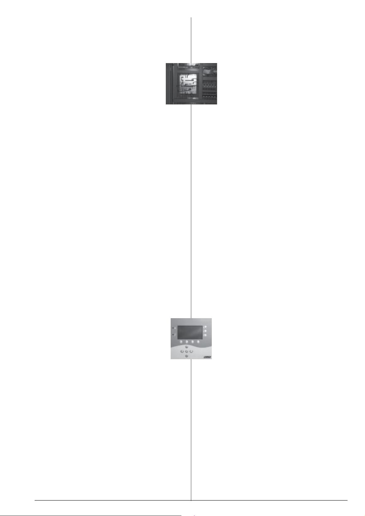
REGELUNG
- Regelung und Überwachung mit dem CLIMATIC™ II
Mikroprozessor und dem KP02 Display
- Anzeige der Wasser-, Luft- und
Kältemitteltemperaturen
- Anzeige der Kältemitteldrücke
- Störungssignalisierung
- Diagnose für jeden Kreislauf
- Anpassung der Temperatursollwerte und Parameter an die
Betriebsbedingungen
- Betriebsstundenzähler und täglicher Ausgleich der
Laufzeiten der Verdichter auf «first in/first out»-Basis
- Fern-Fehlermeldung
- Fern-Sollwertveränderung (Option)
- Leistungsregelung in Abhängigkeit von der
Wassereintrittstemperatur mit Ausgleich durch
Austrittstemperatur
- Frostschutz (wenn Wasser nicht mit Frostschutzmittel
gemischt wird)
KÄL TETECHNISCHE OPTIONEN
- Kältemittel R22 (außerhalb der EU, nur ab MCC 92 S, gemäß
der europäischen Bestimmung Nr. 2037/2000)
- Kaltwasserströmungsschalter
- Hochdruck- und Niederdruckmanometer
- Ölmanometer (nur MCC P)
- Eine Extraleistungsstufe (nur MCC P)
- Verdichter-Ansaugventil (nur MCC P)
- Ganzjahresbetrieb
- Verstärkte Verdampferisolierung (Stärke 25,4 mm)
- Auswechselbare Filtertrocknerpatrone
- Elektronisches Expansionsventil
- Druckgeregeltes Heißgaseinspritzventil am MCC S mit zwei
Verdichtern
- Konformität mit der TÜV- & STEK-Norm
CONTROL
- Control and check by CLIMATIC™ II
microprocessor, KP02 display
- Reading of water, air and refrigerant
temperatures
- Reading of refrigerant pressures
- Alarm signalling
- Diagnostic per circuit
- Adjustment of temperature setpoints ans
parameters adapted to operating conditions
- Hour counter and daily balance of operating time for each
compressor by "first in/first out" basis
- Remote default signal
- Remote setpoint set-back (option)
- Capacity control in accordance with water inlet temperature
with balancing by outlet temperature
- Antifreeze protection (if water is not mixed with anti freeze)
REFRIGERA TING OPTIONS
- R22 refrigerant (out of E.E.C., only from MCC 92 S, according
to european regulation nr 2037/2000)
- Chilled water flow switch
- High and low pressure gauge
- Oil gauge (MCC P only)
- One extra capacity step (MCC P only)
- Compressor suction valve (MCC P only)
- All season operation
- Re-inforced evaporator insulation (thickness 25,4 mm)
- Removable cartridge filter-drier
- Electronic expansion valve
- Pressure controlled hot gas injection valve on MCC S with
two compressors
- TUV & STEK standard conformity
ELEKTRISCHE OPTIONEN
- KP 07 Grafik-Display
- No separated supply
- Keine getrennte Stromversorgung
- Hauptschalter
- Fehlermeldung für jeden Kreislauf
- Teilwicklungsanlauf der Verdichter (nur MCC P
Maschinen)
SCHALLDÄMMOPTIONEN (SI-VERSION)
- Geräuschdämmung des Verdichters mit
Geraüschdämmmatten.
LACKIERUNGSOPTIONEN
- Verflüssiger-Schutzgitter
- »BLYGOLD PLUS» Schutzlackierung an den Registern
- Paneele im unteren Teil der Maschine
HOCHTEMPERA TUROPTION
- Horizontaler Ausblas
- Verfügbarer statischer Druck, Konfiguration für
Kanalanschluss: 150, 200, 250 oder 300 Pa (außer bei
verschiedenen Modellen - siehe Tabelle «Verflüssiger»
Seite 10)
- Verfügbarer statischer Druck, Konfiguration mit freiem
Auslass: 100, 150, 200, 250 oder 300 Pa (außer bei
verschiedenen Modellen - siehe Tabelle «Verflüssiger»
Seite 10 & 11)
ELECTRICAL OPTIONS
- KP 07 graphic display
- No separated supply
- Main switch
- Each circuit default signal
- Compressors part-winding start (on MCC P units
only)
LOW NOISE OPTION (SI VERSION)
- Compressor noise insulation by sound-proofing foam
COA TING OPTIONS
- Coils protection grille
- "BLYGOLD PLUS" protection on coils
- Panels at lower part of the unit
HIGH TEMPERATURE OPTION
- Horizontal discharge
- Available static pressure, ducted oulet configuration : 150,
200, 250 or 300 Pa (except on several models - see table
"condensers" page 10)
- Available static pressure, unducted outlet configuration :
100, 150, 200, 250 or 300 Pa (except on several models see table "condensers" page 10 & 11)
MCC_AGU/0102-G • 3 •
Page 6
OPTION HYDRAULISCHES MODUL AN MCC
MASCHINEN
MCC 71 S bis MCC 282 P :
Integriertes oder unabhängiges Hydraulikmodul
HYDRAULIC MODULE OPTION ON MCC UNITS
MCC 71 S to MCC 282 P :
Integrated or independent hydraulic module
MCC 302 P und 382 P :
Nur unabhängiges Hydraulikmodul
Länge des integrierten Moduls : 1.260 mm
Leitungen vom Wärmetauscher bis zum Hydraulikmodul
außerhalb der Maschine
Standardmäßig erhältliche Ausstattungsteile :
- 250 Liter Behälter
- Eine einfache Pumpe
- 36 l. Ausdehnungsgefäß + Ventil
- Verfügbarer Mindestdruck 14 mWS (bei für Qo berechnete
Kaltwasser-Strömungsgeschwindigkeit mit glykolfreiem
Wasser 12/7 °C und Luft 35 °C)
Optional erhältliche Ausstattungsteile :
- Manuelles Pumpenansaugventil
- Einfaches Manometer
- Differenzdruckmanometer mit 3 Anschlüssen
(Pumpeneinlass / Pumpenauslass/
- Überdruckventil
- Manuelle Einlass-/Auslass-Absperrventile
(installationsfertig angeliefert)
- Einlass-/Auslass-Alkoholthermometer (installationsfertig
angeliefert)
- Biegsame Einlass-/Auslassstutzen (installationsfertig
angeliefert)
MCC 302 P et 382 P :
Only independent hydraulic module
Length of the integrated module : 1260 mm
Piping from exchanger to hydraulic equipment located outside
the unit
Standard available equipments :
- 250 liters receiver
- One single pump
- 36 l. expansion vessel + valve
- Minimum available pressure 14 mCW (for chilled water flow
rate calculated for Qo with non glycolated water 12/7°C and
air 35°C)
Optional available equipments :
- Pump suction manual valve
- Simple gauge
- Differential gauge with 3 taps (pump inlet/pump outlet/départ production
- Relief valve
- In/Out manual isolating valves (shipped ready for installation)
- In/out alcohol thermometers (shipped ready for installation)
- In/out flexible sleeves (shipped ready for installation)
Verkleidung der hydraulischen Ausstattung :
- Die Paneelen im oberen Teil sind Standard
- Die Paneelen im unteren Teil sind eine Option
ACHTUNG :
Die Rohrdurchmesser des Hydraulikmoduls und die MCCStandardrohrdurchmesser sind unterschiedlich.
Bei allen MCC (außer 302 P & 382 P) werden dieselben
unabhängigen Hydraulikmodule verwendet wie bei der WABaureihe.
BEISPIELE FÜR DIE TYPENBEZEICHNUNG DER MASCHINEN
EXAMPLES OF UNITS RANGES DESIGNATIONS
MCC102SK
Hydraulic equipment casing :
- Panels at upper parts in standard
- Panels at the lower part as an option
ATTENTION :
Hydraulic piping diameters and standard MCC ones are
different.
For each MCC (except 302 P & 382 P), independent
hydraulic modules are the same as MCH range ones.
K Betrieb mit R407C
R407C operating (R22 if no other precision)
"S" Spiralverdichter - Scroll compressor
"P" Hubkolbenverdichter - Reciprocating compressor
Anzahl der Kühlkreisläufe
Number of refrigerating circuits
Nenn-Kälteleistung in Zehntel kW
Nominal capacity expressed in tens of kW
"C" Radialventilatoren - Centrifugal fans
"C" Kühler -Chiller
"M"
Mittlere Leistung - Medium (60
• 4 • MCC_AGU/0102-G
!
300 kW)
Page 7
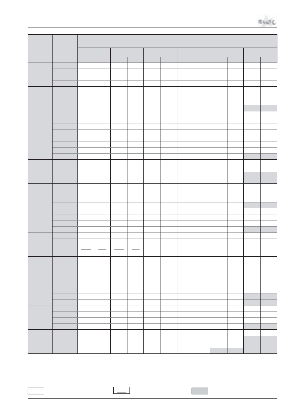
LEISTUNGSTABELLEN - WASSER
PERFORMANCE TABLES - WATER
MODELL
TYPES
MCC
71 SK
MCC
81 SK
MCC
92 SK
MCC
102 SK
MCC
132 SK
MCC
162 SK
MCC
192 PK
MCC
212 PK
MCC
242 PK
MCC
282 PK
MCC
302 PK
MCC
322 PK
Wasseraustritts-
temperatur
Water outlet
temperature
°C
5 64,0 17,5 62,0 18,7 60,6 19,6 59,1 20,5 56,9 21,9 54,5 23,4
7 68,4 17,9 66,2 19,2 64,7 20,1 63,1 21 60,7 22,5 58,2 24
9 72,9 18,4 70,6 19,7 68,9 20,6 67,3 21,8 64,7 23 62,1 24,5
11 78,0 18,9 75,1 20,2 73,3 21,2 71,5 22,4 68,8 23,6 66,1 25,1
5 75,6 22,1 73,1 23,7 71,5 24,8 69,7 25,9 67,1 27,7 64,4 29,5
7 80,8 22,7 78,0 24,3 76,2 25,4 74,4 26,6 71,5 28,4 68,6 30,2
9 86,0 23,2 83,0 24,9 81,1 26,1 79,1 27,6 76,0 29,1 73,0 31
11 91,5 23,8 88,3 25,5 86,1 26,7 83,9 28,3 80,8 29,8 47,3 12,8
5 90,7 24,9 88,1 26,6 86,2 27,9 84,3 29,2 81,2 31,4 78,0 33,7
7 97,1 25,4 94,1 27,2 92,1 28,5 90,0 29,9 86,7 32,1 83,3 34,4
9 104,0 26 100,4 27,9 98,3 29,2 96,0 31 92,5 32,8 88,9 35,1
11 110,2 26,6 107,1 28,5 105,1 29,9 102,2 31,7 98,5 33,5 94,8 35,9
5 108,2 30 105,1 32,1 103,0 33,5 100,7 35,1 97,1 37,5 93,1 40,1
7 116,4 30,7 112,3 32,8 110,2 34,3 108,2 35,9 104,0 38,4 99,6 41
9 123,6 31,4 120,5 33,6 117,4 35,2 114,3 37,2 110,2 39,3 106,1 42
11 131,8 32,2 127,7 34,5 124,6 36,1 122,6 38,2 117,4 40,2 88,9 27,4
5 136,0 38,3 130,8 40,9 127,7 42,8 124,6 44,7 119,5 47,6 114,3 50,5
7 144,2 39,3 139,1 42,1 136,0 44 132,9 45,9 127,7 48,8 121,5 51,8
9 153,5 40,4 148,3 43,3 144,2 45,3 140,1 47,9 134,9 50,1 77,8 21,6
11 162,7 41,5 156,6 44,6 152,4 46,6 148,3 49,3 143,2 51,5 82,8 22
5 163,8 44,4 157,6 47,4 154,5 49,6 150,4 51,8 145,2 55,4 139,1 59,1
7 174,1 45,3 167,9 48,5 163,8 50,7 160,7 53 154,5 56,6 148,3 60,4
9 185,4 46,3 178,2 49,6 174,1 51,9 170,0 54,9 163,8 57,9 157,6 61,7
11 196,7 47,3 189,5 50,8 184,4 53,2 180,3 56,2 173,0 59,2 100,0 25,4
5 192,4 58,1 184,1 60,1 178,9 61,4 173,7 62,7 166,4 64,5 158,1 66,1
7 204,9 60,4 196,6 62,6 191,4 64 186,2 65,3 177,8 67,2 169,5 68,9
9 218,4 62,8 209,0 65,2 203,8 66,6 197,6 68 189,3 69,9 181,0 71,7
11 231,9 65,2 222,6 67,8 216,3 69,3 210,1 70,7 201,8 72,7 146,6 49,8
5 217,4 61 209,0 63,4 203,8 65 198,6 66,6 190,3 68,9 182,0 71,2
7 231,9 63,3 223,6 65,9 218,4 67,6 212,2 69,2 203,8 71,7 194,5 74,1
9 247,5 65,6 238,2 68,4 231,9 70,2 226,7 71,9 217,4 74,5 208,0 76,9
11 264,2 67,9 253,8 70,9 247,5 72,8 241,3 74,6 231,9 77,2 222,6 79,7
5 242,6 68,1 233,1 70,9 227,9 72,7 221,6 74,5 212,1 77,1 203,7 79,7
7 259,4 70,7 248,9 73,7 242,6 75,6 236,3 77,5 226,8 80,2 217,4 82,9
9 276,2 73,3 265,7 76,5 258,3 78,5 252,0 80,4 242,6 83,3 232,1 86
11 294,0 75,8 282,5 79,2 275,1 81,3 267,8 83,4 257,3 86,2 247,8 89
5 276,2 83,7 265,7 86,7 258,3 88,6 252,0 90,4 241,5 93,1 232,1 95,7
7 295,1 87,2 283,5 90,4 276,2 92,4 268,8 94,3 258,3 97 247,8 99,6
9 314,0 90,6 301,4 94,1 293,0 96,2 285,6 98,2 275,1 101 217,4 78,4
11 332,9 94 319,2 97,8 310,8 100 303,5 102 293,0 105 231,0 81,1
5 333,9 101 321,3 104 312,9 106 304,5 109 291,9 112 279,3 114
7 356,0 104 342,3 108 332,9 111 324,5 113 310,8 116 298,2 119
9 378,0 108 363,3 113 353,9 115 344,4 118 330,8 121 317,1 124
11 401,1 112 385,4 117 374,9 120 365,4 123 351,8 126 277,2 97,8
5 378,0 112 363,3 116 353,9 118 344,4 121 330,8 124 261,5 97,1
7 402,2 116 385,4 121 375,9 124 365,4 126 351,8 130 279,3 101
9 426,3 121 408,5 126 398,0 129 387,5 132 373,8 135 297,2 105
11 451,5 126 431,6 131 420,0 135 409,5 137 329,7 106 316,1 109
25°C 28°C 30°C 32°C 35°C 38°C
Qo P Qo P Qo P Qo P Qo P Qo P
Lufteintrittstemperatur
Air inlet temperature
Qo : Kälteleistung in kW
Cooling capacity in kW
XXX
∆T Wasser = 5°C
Water ∆T = 5°C
P : Leistungsaufnahme der Verdichter in kW
Compressors power input in kW
XXX
∆T Wasser = 6°C
Water ∆T = 6°C
Verschmutzungsfaktor:
Fouling factor : 0,44 m²C/kW
XXX
Hochdruck-Entlastungsbetrieb
High pressure offloading operation
MCC_AGU/0102-G • 5 •
Page 8
LEISTUNGSTABELLEN - WASSER + 30 % ETHYLENGLYKOL
PERFORMANCE TABLES - WATER + 30% ETHYLENE GLYCOL
MODELL MCC 71 SK
Wasseraustritts
- temperatur
MODELL
TYPES
MCC
71 SK
MCC
81 SK
MCC
92 SK
MCC
102 SK
MCC
132 SK
MCC
162 SK
°C 25°C 28°C 30°C 32°C 35°C 38°C
Water outlet
Temperature
-10 34,8 14,7 33,7 15,6 33,0 16,2 32,2 16,9 31,1 18,0 29,8 19,3
-8 37,9 15,0 36,8 15,9 36,0 16,6 35,2 17,3 33,9 18,5 32,6 19,7
-5 42,9 15,4 41,7 16,4 40,7 17,1 39,9 17,9 38,3 19,1 36,8 20,5
0 53,2 16,4 51,7 17,5 50,5 18,3 49,4 19,1 47,5 20,5 45,5 21,9
4 61,1 17,1 59,2 18,3 58,0 19,1 56,6 20,0 54,4 21,4 52,1 22,9
7 67,5 17,7 65,4 18,9 63,9 19,8 62,5 20,8 60,1 22,2 57,6 23,7
10 74,6 18,4 72,1 19,7 70,5 20,6 68,8 21,6 66,2 23,1 63,5 24,6
-10 42,4 19,7 41,0 20,8 39,9 21,6 38,9 22,5 37,4 23,9 35,8 25,5
-8 46,0 20,0 44,4 21,2 43,4 22,1 42,2 23,0 40,6 24,5 38,9 26,2
-5 51,9 20,7 50,1 21,9 48,9 22,8 47,8 23,8 45,9 25,4 43,9 27,2
0 62,7 20,7 60,9 22,0 59,6 22,9 58,3 23,9 56,3 25,5 54,1 27,3
4 72,0 21,6 69,8 23,1 68,3 24,1 66,7 25,2 64,3 27,0 61,7 28,8
7 79,7 22,4 77,1 24,0 75,4 25,1 73,5 26,2 70,8 28,0 67,9 29,9
10 87,8 23,2 84,8 24,9 82,8 26,1 80,7 27,3 77,7 29,1 74,7 31,0
-10 49,7 22,0 48,2 23,3 47,3 24,3 46,3 25,4 44,9 27,1 43,6 29,0
-8 54,0 22,3 52,4 23,7 51,3 24,7 50,3 25,8 48,7 27,6 47,0 29,6
-5 61,0 22,9 59,2 24,3 58,0 25,3 56,8 26,5 54,8 28,3 52,8 30,4
0 75,3 23,5 73,2 25,0 71,7 26,2 70,1 27,4 67,7 29,4 65,0 31,7
4 86,5 24,4 84,0 26,1 82,3 27,3 80,5 28,6 77,6 30,7 74,6 33,0
7 95,9 25,2 93,0 26,9 91,0 28,2 88,9 29,6 85,8 31,7 82,4 34,1
10 106,1 26,0 102,6 27,9 100,4 29,2 98,1 30,6 94,6 32,8 90,9 35,2
-10 58,8 25,7 57,1 27,3 56,0 28,5 54,8 29,6 53,0 31,6 - -
-8 64,2 26,2 62,3 27,8 61,0 29,0 59,7 30,2 57,8 32,2 55,7 34,5
-5 72,7 26,9 70,6 28,6 69,1 29,8 67,6 31,1 65,2 33,3 62,7 35,6
0 89,9 28,2 87,4 30,1 85,7 31,4 83,8 32,8 80,7 35,1 77,5 37,6
4 103,2 29,4 100,4 31,4 98,3 32,8 96,1 34,3 92,6 36,7 88,9 39,3
7 114,5 30,4 111,3 32,4 109,2 33,9 106,1 35,5 102,5 38,0 98,4 40,6
10 126,0 31,4 122,9 33,6 1 19,7 35,2 117,6 36,8 113,4 39,3 108,2 42,0
-10 75,9 31,3 73,4 33,3 71,7 34,7 69,9 36,1 67,2 38,5 64,2 41,2
-8 82,6 32,1 80,0 34,1 78,1 35,5 76,1 37,0 73,1 39,5 69,7 42,3
-5 93,3 33,2 90,3 35,4 88,2 36,9 85,9 38,5 82,3 41,1 78,4 43,9
0 113,4 35,5 110,3 37,8 107,1 39,5 105,0 41,3 100,5 44,1 95,9 47,0
4 130,2 37,3 125,0 39,8 122,9 41,6 119,7 43,5 114,5 46,4 109,2 49,3
7 142,8 38,7 137,6 41,5 134,4 43,3 131,3 45,3 126,0 48,2 120,8 51,1
10 156,5 40,4 150,2 43,3 147,0 45,2 142,8 47,2 137,6 50,1 79,6 21,6
-10 92,2 39,7 88,9 41,9 86,7 43,6 84,5 45,3 81,2 48,2 77,7 51,4
-8 100,1 40,4 96,7 42,8 94,4 44,5 92,0 46,3 88,4 49,3 84,6 52,7
-5 112,4 41,6 109,2 44,1 107,1 45,9 104,0 47,9 100,0 51,1 95,7 54,6
0 135,5 41,6 131,3 44,3 128,1 46,2 126,0 48,2 120,8 51,4 1 16,6 54,9
4 155,4 43,4 150,2 46,3 147,0 48,4 143,9 50,6 138,6 54,0 132,3 57,7
7 171,2 44,8 165,9 47,9 161,7 50,1 157,5 52,4 152,3 55,9 146,0 59,7
10 188,0 46,2 181,7 49,5 177,5 51,9 173,3 54,2 165,9 57,9 159,6 61,6
!!
! MCC 162 SK
!!
Lufteintrittstemperatur
Air inlet temperature
Qo P Qo P Qo P Qo P Qo P Qo P
Qo : Kälteleistung in kW
Cooling capacity in kW
XXX
∆T Wasser = 5°C
Water ∆T = 5°C
P : Leistungsaufnahme der Verdichter in kW
Compressors power input in kW
XXX
∆T Wasser = 6°C
Water ∆T = 6°C
Verschmutzungsfaktor:
Fouling factor : 0,44 m²C/kW
XXX
Hochdruck-Entlastungsbetrieb
High pressure offloading operation
• 6 • MCC_AGU/0102-G
Page 9

LEISTUNGSTABELLEN - WASSER + 30 % ETHYLENGLYKOL
PERFORMANCE TABLES - WATER + 30% ETHYLENE GLYCOL
MODELL MCC 192 PK
Wasseraustritts
- temperatur
MODELL
TYPES
MCC
192 PK
MCC
212 PK
MCC
242 PK
MCC
282 PK
MCC
302 PK
MCC
322 SK
°C 25°C 28°C 30°C 32°C 35°C 38°C
Water outlet
Temperature
-10 102,6 39,9 98,3 41,1 95,3 41,9 92,3 42,7 87,6 43,8 82,7 44,9
-8 112,4 42,0 107,1 43,3 104,4 44,1 101,1 45,0 96,0 46,2 90,6 47,4
-5 128,1 45,2 122,9 46,6 118,7 47,6 115,5 48,5 109,2 49,8 103,4 51,1
0 155,4 50,8 149,1 52,4 144,9 53,5 140,7 54,6 134,4 56,2 127,1 57,7
4 179,6 55,4 172,2 57,3 168,0 58,6 162,8 59,8 155,4 61,5 148,1 63,1
7 198,5 59,0 191,1 61,1 185,9 62,4 180,6 63,7 172,2 65,6 164,9 67,3
10 218,4 62,6 210,0 65,0 204,8 66,4 198,5 67,8 191,1 69,7 182,7 71,5
-10 114,5 41,4 110,3 42,9 107,1 43,9 104,3 44,8 99,6 46,3 95,0 47,8
-8 125,0 43,9 120,8 45,5 117,6 46,5 114,5 47,6 109,2 49,1 104,0 50,7
-5 142,8 47,6 137,6 49,3 133,4 50,4 130,2 51,6 123,9 53,3 118,7 55,0
0 174,3 53,5 168,0 55,5 163,8 56,8 159,6 58,2 153,3 60,2 146,0 62,2
4 202,7 58,3 195,3 60,5 190,1 62,1 184,8 63,6 177,5 65,8 169,1 68,0
7 224,7 61,8 216,3 64,3 211,1 66,0 205,8 67,6 197,4 70,0 189,0 72,4
10 247,8 65,3 239,4 68,1 233,1 69,9 226,8 71,6 218,4 74,2 209,0 76,7
-10 130,2 46,0 125,0 47,7 121,8 48,8 1 18,7 50,0 113,4 51,7 108,2 53,5
-8 141,8 49,0 136,5 50,8 133,4 52,0 129,2 53,2 123,9 55,0 117,6 56,9
-5 160,7 53,3 155,4 55,2 151,2 56,5 147,0 57,9 140,7 59,9 133,4 62,0
0 196,4 60,0 189,0 62,3 183,8 63,9 178,5 65,4 171,2 67,8 163,8 70,2
4 226,8 65,4 218,4 68,0 212,1 69,8 206,9 71,5 198,5 74,1 190,1 76,7
7 251,0 69,4 241,5 72,3 235,2 74,2 228,9 76,0 219,5 78,7 211,1 81,4
10 276,2 73,2 265,7 76,5 259,4 78,5 252,0 80,5 242,6 83,3 233,1 86,1
-10 150,2 56,7 143,9 58,4 139,7 59,6 136,5 60,8 130,2 62,5 - -
-8 162,8 60,1 156,5 62,0 152,3 63,2 148,1 64,5 141,8 66,4 - -
-5 183,8 65,2 177,5 67,2 172,2 68,5 168,0 69,9 160,7 72,0 153,3 74,2
0 223,7 73,4 215,3 75,8 210,0 77,4 203,7 79,0 195,3 81,4 186,9 83,8
4 257,3 80,2 247,8 83,0 241,5 84,8 235,2 86,5 225,8 89,2 216,3 91,7
7 284,6 85,3 274,1 88,4 266,7 90,4 259,4 92,3 249,9 95,0 240,5 97,7
10 312,9 90,5 300,3 94,0 293,0 96,1 285,6 98,1 275,1 101,0 217,4 78,5
-10 184,8 70,8 177,5 72,2 172,2 73,2 167,0 74,0 159,6 75,3 151,2 76,4
-8 200,6 74,4 193,2 76,1 188,0 77,1 182,7 78,2 174,3 79,6 164,9 81,0
-5 226,8 79,8 218,4 81,8 212,1 83,1 206,9 84,4 197,4 86,2 186,9 88,0
0 272,0 88,9 262,5 91,6 255,2 93,3 248,9 95,0 237,3 97,5 225,8 100,0
4 311,9 96,5 300,3 100,0 293,0 102,0 284,6 104,0 273,0 107,0 260,4 1 10,0
7 344,4 102,0 330,8 106,0 322,4 108,0 314,0 111,0 301,4 114,0 288,8 117,0
10 377,0 108,0 363,3 113,0 353,9 1 15,0 344,4 118,0 330,8 121,0 261,5 94,5
-10 203,7 79,0 197,4 81,5 193,2 83,1 189,0 84,6 181,7 86,8 - -
-8 222,6 82,8 215,3 85,4 211,1 87,1 205,8 88,7 197,4 91,1 189,0 93,3
-5 252,0 88,4 244,7 91,3 238,4 93,2 233,1 95,0 223,7 97,7 213,2 100,0
0 306,6 98,3 295,1 102,0 287,7 104,0 280,4 106,0 269,9 109,0 258,3 112,0
4 351,8 107,0 339,2 11 1,0 330,8 113,0 322,4 1 16,0 308,7 119,0 296,1 122,0
7 388,5 114,0 372,8 118,0 363,3 121,0 353,9 123,0 340,2 127,0 270,9 99,1
10 425,3 121,0 407,4 126,0 396,9 129,0 386,4 131,0 372,8 135,0 298,2 105,0
!!
! MCC 322 PK
!!
Lufteintrittstemperatur
Air inlet temperature
Qo P Qo P Qo P Qo P Qo P Qo P
Qo : Kälteleistung in kW
Cooling capacity in kW
XXX
∆T Wasser = 5°C
Water ∆T = 5°C
P : Leistungsaufnahme der Verdichter in kW
Compressors power input in kW
XXX
∆T Wasser = 6°C
Water ∆T = 6°C
Verschmutzungsfaktor:
Fouling factor : 0,44 m²C/kW
XXX
Hochdruck-Entlastungsbetrieb
High pressure offloading operation
MCC_AGU/0102-G • 7 •
Page 10

TECHNISCHE DATEN
TECHNICAL DATA
VERDICHTER UND KÄL TEMITTELKREISLÄUFE - COMPRESSORS AND REFRIGERANT CIRCUITS
MODELL - TYPE MCC 71 S 81 S 92 S 102 S 132 S 162 S
Verdichtertyp
Compressor type Schraubenverdichter
Anzahl Verdichter / Anzahl Kältekreise
Number of compressors / Number of circuits 2/1 4/2
Leistungsstufen je Verdichter
Capacity steps for each compressor % 0-50-100 0-25-50-75-100
Kältemittelfüllung je Kältekreis
Refrigerant charge per circuit kg 8 9 11 14 + 11 1 4 17
Ölfüllung je Verdichter
Oil charge per compressor l4
Kurbelwannenheizung je Verdichter
Crankcase heater per compressor W70
MODELL - TYPE MCC 192 P 212 P 242 P 282 P 302 P 322 P
Verdichtertyp Halbhermetischer Hubkolbenverdichter
Compressor type Semi-hermetic reciprocating type
Anzahl Verdichter / Anzahl Kältekreise
Number of compressors / Number of circuits 2/2
Leistungsstufen je Verdichter 0-33-50 ~ 0-38-50 0-33-50 0-38-50
Capacity steps for each compressor % 83-100 88-100 83-100 88-100
Kältemittelfüllung je Kältekreis 23+
Refrigerant charge per circuit kg 20 20 23 25 31 34
Ölfüllung je Verdichter 7,7 +
Oil charge per compressor l 7,4 7,4 7,7 7,7 7,7 7,5
Kurbelwannenheizung je Verdichter
Crankcase heater per compressor W 200
VERDAMPFER - EVAPORATORS
MODELL - TYPE MCC 71 S 81 S 92 S 102 S 132 S 162 S
Anzahl
Number 1
Wassermenge
Water volume dm
Wasserrohre PN 16 PN 16 PN 16 PN 16
Water piping (1) 2"1/2 2"1/2 DN 80 DN 80 DN 100 DN 100
Testdruck - bar Wasser - Water 15 15 15 15 15 15
Test pressure - Bar Kältemittel 27 27 27 27 34 34
Betriebsdruck - bar Wasser - Water 10 10 10 10 10 10
Operating pressure - Bar Kältemittel 24,5 24,5 24,5 24,5 17 17
MODELL - TYPE MCC 192 P 212 P 242 P 282 P 302 P 322 P
Anzahl
Number 1
Wassermenge
Water volume dm
Wasserrohre PN 16 PN 16 PN 16 PN 16 PN16 PN16
Water piping (1) DN 100 DN 100 DN 150 DN 150 DN150 DN150
Testdruck - bar Wasser - Water 15 15 15 15 15 15
Test pressure - Bar Kältemittel 34 34 34 34 34 34
Betriebsdruck - bar Wasser - Water 10 10 10 10 10 10
Operating pressure - Bar Kältemittel 17 17 17 17 17 17
(1) : MCC 71 S & 81 S : Geschraubt- Threaded
MCC 92 S
!!
! 322 P : Flansche - Flanges
!!
3
17 20 29 31 43 43
3
48 48 82 82 77 77
• 8 • MCC_AGU/0102-G
Page 11

VERFLÜSSIGER - CONDENSERS
MCC 71 SK
MODELL - TYPE MCC 71 S/ 81 S/ 92 S 102 S 132 S 162 S
Lüftungstyp Radialventilator - Riemenantrieb
Ventilation type Centrifugal fan - Belt pulley transmission
Ventilatoranzahl
Fan number 222223
Luft menge
Air flow rate m3/h 18 200 20 000 29 000 41 000 41 000 49 500
Max. verfügbarer Druck, Konfiguration "mit Kanalanschluss"
Maxi available pressure "ducted outlet configuration" Pa 300 300 300 200 200 300
Available static pressure "ducted outlet" configuration
Verfügbarer statischer Druck, Konfiguration "nicht kanalisierter Auslass"
Available static pressure "unducted outlet" configuration
Verfügbarer statischer Druck, Konfiguration "nicht kanalisierter Auslass"
MCC_AGU/0102-G • 9 •
!!
! MCC 162 SK
!!
Ventilatordrehzahl
Fan speed RP M 486 515 641 801 801 675
Gesamtleistungsaufnahme
Total input kW 1,1 1,5 3 7,5 7,5 4
Stromaufnahme je V entilator
Each fan current draw A m p 2,7 3,6 7 15,8 15,8 9,1
Ventilatordrehzahl
Fan speed RP M 543 572 675 858 858 715
Gesamtleistungsaufnahme
Total input kW 1,1 1,5 3 7,5 7,5 4
Stromaufnahme je V entilator
Each fan current draw A m p 2,7 3,6 7 15,8 15,8 9,1
Ventilatordrehzahl
Fan speed RP M 606 641 715 858 858 755
Gesamtleistungsaufnahme
Total input kW 1,5 1,8 4 7,5 7,5 5,5
Stromaufnahme je V entilator
Each fan current draw A m p 3,6 4,3 9,1 15,8 15,8 12
Ventilatordrehzahl
Fan speed RP M 675 675 755 801
Gesamtleistungsaufnahme
Total input kW 1,8 1,8 4 5,5
250 Pa 150 Pa200 Pa 100 Pa300 Pa
Stromaufnahme je V entilator
Each fan current draw A m p 4,3 4,3 9,1 12
Ventilatordrehzahl
Fan speed RP M 715 715 801 858
Gesamtleistungsaufnahme
Total input kW 1,8 2,2 4 5,5
Stromaufnahme je V entilator
Each fan current draw A m p 4,3 5,2 9,1 12
Ventilatordrehzahl
Fan speed RP M 606 641 801 915
Gesamtleistungsaufnahme
Total input kW 1,5 1,8 4 7,5
Stromaufnahme je V entilator
Each fan current draw A m p 3,6 4,3 9,1 15,8
Ventilatordrehzahl
Fan speed RP M 675 675 858 972
Gesamtleistungsaufnahme
Total input kW 1,8 1,8 5,5 7,5
Stromaufnahme je V entilator
Each fan current draw A m p 4,3 4,3 12 15,8
Ventilatordrehzahl
Fan speed RP M 715 755 955 972
Gesamtleistungsaufnahme
Total input kW 2,2 3 5,5 7,5
Stromaufnahme je V entilator
Each fan current draw A m p 5,2 7 12 15,8
Ventilatordrehzahl
Fan speed RP M 755 801 915 1030
Gesamtleistungsaufnahme
Total input kW 2,2 3 5,5 7,5
250 Pa 150 Pa200 Pa 100 Pa300 Pa
Stromaufnahme je V entilator
Each fan current draw A m p 5,2 7 12 15,8
Ventilatordrehzahl
Fan speed RP M 801 858 972 1030
Gesamtleistungsaufnahme
Total input kW 2,2 3 5,5 7,5
Stromaufnahme je V entilator
Each fan current draw Amp 5,2 7 12 15,8
Nicht verfügbar
Not available
Nicht verfügbar
Not available
Nicht verfügbar
Not available
Nicht verfügbar
Not available
Nicht verfügbar
Not available
Nicht verfügbar
Not available
Nicht verfügbar
Not available
Page 12

VERFLÜSSIGER - CONDENSERS
MCC 192 PK
MODELL - TYPE MCC 192 P 212 P 242 P 282 P 302 P 322 P
Lüftungstyp Radialventilator - Riemenantrieb
Ventilation type Centrifugal fan - Belt pulley transmission
Ventilatoranzahl
Fan number 344455
Luft menge
Air flow rate m3/h 61 500 77 000 77 000 82 000 102 500 102 500
Max. verfügbarer Druck, Konfiguration "mit Kanalanschluss"
Maxi available pressure "ducted outlet configuration" Pa 200 300 300 200 200 200
Available static pressure ducted outlet configuration
Verfügbarer statischer Druck, Konfiguration mit Kanalanschluss
Konfiguration "freier Ausblas" bei den MCC P Modellen nicht möglich.
"Unducted outlet" configuration non feasible on MCC P models.
!!
! MCC 322 PK
!!
Ventilatordrehzahl
Fan speed RP M 801 755 755 801 801 801
Gesamtleistungsaufnahme
Total input kW 7.5 5.5 5.5 7.5 7.5 7.5
100 Pa300 Pa
Stromaufnahme je V entilator
Each fan current draw Am p 15.8 12 12 15.8 15.8 15.8
Ventilatordrehzahl
Fan speed RP M 858 801 801 858 858 858
Gesamtleistungsaufnahme
Total input kW 7.5 7.5 7.5 7.5 7.5 7.5
Stromaufnahme je V entilator
Each fan current draw Am p 15.8 15.8 15.8 15.8 15.8 15.8
Ventilatordrehzahl
Fan speed RP M 858 858 858 858 858 858
Gesamtleistungsaufnahme
Total input kW 7.5 7.5 7.5 7.5 7.5 7.5
200 Pa
Stromaufnahme je V entilator
Each fan current draw Am p 15.8 15.8 15.8 15.8 15.8 15.8
Ventilatordrehzahl
Fan speed RP M 858 858
Gesamtleistungsaufnahme
Total input kW 7.5 7.5
250 Pa 150 Pa
Stromaufnahme je V entilator
Each fan current draw Am p 15.8 15.8
Ventilatordrehzahl
Fan speed RP M 915 915
Gesamtleistungsaufnahme
Total input kW 7.5 7.5
Stromaufnahme je V entilator
Each fan current draw Amp 15.8 15.8
Nicht
verfügbar
Not available
Nicht
verfügbar
Not available
Nicht verfügbar
Not available
Nicht verfügbar
Not available
Elektrische Daten
ELECTRICAL DATA
MODELL - TYPE MCC 71 S 81 S 92 S 102 S 132 S 162 S
Max. Leistung
Maxi power kW 30 36 43 61 71 77
Max. Strom
Maxi current A 54 64 83 113 126 139
Direktanlauf-Stromstärke
Direct start up intensity A 205 255 225 360 375 355
MODELL - TYPE MCC 192 P 212 P 242 P 282 P 302 P 322 P
Max. Leistung
Maxi power kW 105 111 118 146 179 190
Max. Strom
Maxi current A 181 203 224 276 333 351
Direktanlauf-Stromstärke
Direct start up intensity A 575 635 655 825 920 890
Teilwicklungsanlauf-Stromstärke
Part Winding start up intensity A 490 525 545 690 770 720
Maximale Strom- und Leistungsaufnahme berechnet bei 400 V/3/50 Hz für Verdichterbetrieb bei +12 / 60 °C
Maximum current and power calculated at 400V/3/50Hz for compressor operation at +12/60°C
• 10 • MCC_AGU/0102-G
Page 13

WASSERSEITIGER DRUCKVERLUST
WATER PRESSURE DROP
GL YKOLFREIES WASSER - NON GLYCOLA TED W A TER
kPa
100
90
80
70
60
50
40
30
Druckverlust (KPa)
Pressure drop (KPa)
20
FG
B
D
A
C
E
10
98765
908070605040302010
100 m³/h
Luftmenge (m3/h)
Air flow rate (m3/h)
VERDAMPFER - EVAPORATORS
Modelle Kurve Max. Wassers.
Type Curve Maxi water flow rate
MCC m3/h
71 S A20
81 S B23
92 S C26
102 S C30
132 S D39
162 S D39
192 P E39
212 P E39
242 P F89
282 P F89
302 P G89
322 P G89
Die Druckverluste werden nur zu Informationszwecken und für glykolfreies
Wasser angegeben. Eine Toleranz von +/- 20 kPa muss bei der Auswahl der
Wasserpumpen berücksichtigt werden.
Pressure drops are given for information only and with non-glycolated water. A
tolerance of +/- 20 kPa must be considered when selecting water pumps.
MCC_AGU/0102-G • 11 •
Page 14

WASSERSEITIGER DRUCKVERLUST (Fort s.)
WA TER PRESSURE DROP (cont'd)
30 % ETHYLENGL YKOL - 30% ETHYLENE GL YCOL
kPa
100
90
80
70
60
50
40
30
Druckverlust (KPa)
Pressure drop (KPa)
20
ABCD
E
FG
10
98765
908070605040302010
100 m³/h
Luftmenge (m3/h)
Air flow rate (m3/h)
VERDAMPFER - EVAPORATORS
Modelle Kurve Max. Wassers.
Type Curve Maxi water flow rate
MCC m3/h
71 S A20
81 S B23
92 S C26
102 S C30
132 S D39
162 S D39
192 P E39
212 P E39
242 P F89
282 P F89
302 P G89
322 P G89
Die Druckverluste werden nur zu Informationszwecken und für glykolfreies
Wasser angegeben. Eine Toleranz von +/- 20 kPa muss bei der Auswahl der
Wasserpumpen berücksichtigt werden.
Pressure drops are given for information only and with non-glycolated water. A
tolerance of +/- 20 kPa must be considered when selecting water pumps.
• 12 • MCC_AGU/0102-G
Page 15

ABMESSUNGEN
DIMENSIONAL DATA
MCC ST ANDARD
STANDARD MCC
1
2
74
478
ES
C
G1/G2 D1/D2 D2/G2 D1/G1
60
30
1101
1161
SE
254
G1/G2/G3 D1/D2/D3 D3/G3 D2/G2 D1/G1
60 60
1101
1161
50
2013
1963
60
30
478
74
50
1963
2013
3030
1541
558 558 362426
n Ø 20
1500
2279
2610
558 717
n Ø 20
1500
B A
ES
V
390
331
1541 1000
558
426
1500
E
3545
3876
B A
1000
E : Einlass - Inlet
S : Auslass - Outlet
362
558
273
S
331
3
4
478
74
50
2033
1983
SE
C
G1/G2/G3/G4
60 60
30 30
SE
309
G1/G2/G3/G4/G5 D1/D2/D3/D4/D5 D5/G5 D4/G4 D3/G3 D2/G2 D1/G1
60
30
1101
1161
D1/D2/D3/D4
478
1101
1161
74
60
30
D4/G4 D3/G3 D2/G2 D1/G1
50
1983
2033
1541 1541
558 558
426
n Ø 20
1300 1300
558 426 558 558 558
n Ø 20
1250 1250
725
558 426 558 362
V
B
4545
4976
1541 1541 1000
1300
A
717717
1250 1250
ES
5811
6242
1000
323
431
362
558426
V
406
1753
869
431
Der Hauptschalter ist eine Option
Main switch is an option
MCC_AGU/0102-G • 13 •
Page 16

ABMESSUNGEN (Forts.) - DIMENSIONAL DA T A (cont'd)
MODELL - TYPE MCC 71 S 81 S 92 S 102 S 132 S 162 S 192 P 212 P 242 P 282 P 302 P 322 P
Zeichnung - Drawing 111112233344
A mm 260 260 310 270 265 265 245 1390 1400 1400 - -
B mm 1160 1310 1400 1500 1480 1480 1795 1795 1755 1755 - -
C mm 280 280 300 300 255 - - 275 310 310 - -
n Ø 20 44444668881010
Gewicht ohne Wasser
Weight without water kg 997 1027 1212 1229 1300 1753 1828 2166 2154 2154 2879 2917
Betriebsgewicht
Operating weight kg 1014 1047 1241 1260 1343 1796 1876 2214 2236 2236 2956 2994
ST ANDARD MCC - LASTVERTEILUNG OHNE GERÄUSCHDÄMMUNG (Betriebsgewichte - kg)
STANDARD MCC - LOAD DISTRIBUTION WITHOUT NOISE INSULATION (operating weights - kg)
MODELL - TYPE MCC 71 S 81 S 92 S 102 S 132 S 162 S 192 P 212 P 242 P 282 P 302 P 322 P
Zeichnung - Drawing 111112233344
D1 kg 297 312 308 312 328 388 354 249 229 229 290 293
D2 kg 154 158 288 297 306 299 308 304 315 315 290 293
D3 kg-----161169262277277264266
D4 kg-------169156156251256
D5 kg----------216216
G1 kg 343 354 339 339 370 407 438 319 306 306 422 422
G2 kg 220 223 306 312 339 323 367 345 370 370 365 368
G3 kg-----218240317343343308312
G4 kg-------249240240275282
G5 kg----------275286
LASTVERTEILUNG MIT GERÄUSCHDÄMMUNGSOPTION (Betriebsgewichte - kg)
LOAD DISTRIBUTION WITH NOISE INSULATION OPTION (operating weights - kg)
MODELL - TYPE MCC 71 S 81 S 92 S 102 S 132 S 162 S 192 P 212 P 242 P 282 P 302 P 322 P
Zeichnung - Drawing 111112233344
Gewicht ohne Wasser
Weight without water kg 1089 1119 1304 1321 1392 1873 1948 2318 2306 2306 3059 3097
Betriebsgewicht
Operating weight kg 1106 1139 1333 1352 1435 1916 1996 2366 2388 2388 3136 3174
D1 kg 320 335 331 335 351 408 374 268 248 248 308 311
D2 kg 177 181 311 320 329 319 328 323 334 334 308 311
D3 kg-----181189281296296282284
D4 kg - - - - - - 188 175 175 269 274
D5 kg----------234234
G1 kg 366 377 362 362 393 427 458 338 325 325 440 440
G2 kg 243 246 329 335 362 343 387 364 389 389 383 386
G3 kg-----238260336362362326330
G4 kg-------268259259293300
G5 kg----------293304
• 14 • MCC_AGU/0102-G
Page 17

ABMESSUNGEN (Forts.) - DIMENSIONAL DA T A (cont'd)
MCC MASCHINE MIT HYDRAULIKMODULOPTION
MCC UNIT WITH HYDRAULIC MODULE OPTION
478
74
1
E
1520
S
C
G1/G2/G3 D1/D2/D3 D3/G3 D2/G2
60
30
1101
1161
1450
50
2013
1963
60
30
1500
ES
1541 1000
558 426 558 362
n Ø 20
1500
3545
3876
E : Einlass - Inlet
S : Auslass - Outlet
D1/G1
V
273
AB
331
2
3
478
74
50
E
1963
2013
1520
S
254
G1/G2/G3/G4 D1/D2/D3/D4 D4/G4 D3/G3 D2/G2 D1/G1
1540
C
60
30
1450
E
S
G1/G2/G3/G4/G5
60
30
1101
1161
1441
60
30
478
74
50
1983
2033
D1/D2/D3/D4/D5 D5/G5 D4/G4 D3/G3 D2/G2 D1/G1
1101
1161
60
30
E
E
1300 13001300
1250 1250
717
558
B
4811
5142
1541 725 1541 1000
558 426
n Ø 20
B
1541
558 426 558
n Ø 20
558 558 426 558
1250 1250 406
5811
6242
362
1000
V
456
S
A
331
362
V
A
S
431
Der Hauptschalter ist eine Option
Main switch is an option
MCC_AGU/0102-G • 15 •
Page 18

ABMESSUNGEN (Forts.) - DIMENSIONAL DA T A (cont'd)
MCC MASCHINE MIT HYDRAULIKMODULOPTION
MCC UNIT WITH HYDRAULIC MODULE OPTION
MODELL - TYPE MCC 71 S 81 S 92 S 102 S 132 S 162 S 192 P 212 P 242 P 282 P 302 P 322 P
Zeichnung - Drawing 1111122333- -
A mm 260 260 310 270 265 265 245 1390 1400 1400 - -
B mm 2905 2905 2855 2895 2895 4160 4185 4035 4030 4030 - -
C mm 280 280 300 300 255 - - 275 310 310 - -
n Ø 20 6666688101010- -
Gewicht ohne Wasser
Weight without water kg 1357 1386 1581 1597 1667 2118 2202 2557 2549 2553 - -
Betriebsgewicht
Operating weight kg 1624 1656 1860 1878 1960 2411 2500 2855 2881 2885 - -
LASTVERTEILUNG MIT HYDRAULIKMODUL UND OHNE GERÄUSCHDÄMMUNG (Betriebsgewichte - kg)
LOAD DISTRIBUTION WITH HYDRAULIC MODULE & WITHOUT NOISE INSULATION (operating weights - kg)
MODELL - TYPE MCC 71 S 81 S 92 S 102 S 132 S 162 S 192 P 212 P 242 P 282 P 302 P 322 P
Zeichnung - Drawing 1111122333- -
D1 kg 266 279 290 292 308 396 385 262 240 240 - -
D2 kg 238 244 326 332 341 246 253 286 295 297 - -
D3 kg 286 286 321 323 323 209 220 255 273 273 - -
D4 kg-----310310231231231--
D5 kg-------299293293--
G1 kg 301 310 312 312 341 442 469 339 317 315 - -
G2 kg 273 277 332 337 361 286 319 326 348 352 - -
G3 kg 260 260 279 282 286 238 260 305 339 339 - -
G4 kg-----284284275277277--
G5 kg-------277268268--
LASTVERTEILUNG MIT HYDRAULIKMODUL UND GERÄUSCHDÄMMUNG (Betriebsgewichte - kg)
LOAD DISTRIBUTION WITH HYDRAULIC MODULE + NOISE INSULATION (operating weights - kg)
MODELL - TYPE MCC 71 S 81 S 92 S 102 S 132 S 162 S 192 P 212 P 242 P 282 P 302 P 322 P
Zeichnung - Drawing 1111122333- -
Gewicht ohne Wasser
Weight without water kg 1589 1618 1813 1829 1899 2372 2456 2841 2833 2837 - -
Betriebsgewicht
Operating weight kg 1856 1888 2092 2110 2192 2665 2754 3139 3165 3169 - -
D1 kg 289 302 313 315 331 415 404 280 258 258 - -
D2 kg 296 302 384 390 399 265 272 304 313 315 - -
D3 kg 321 321 356 358 358 263 274 273 291 291 - -
D4 kg-----345345284284284--
D5 kg-------334328328--
G1 kg 324 333 335 335 364 461 488 357 335 333 - -
G2 kg 331 335 390 395 419 305 338 344 366 370 - -
G3 kg 295 295 314 317 321 292 314 323 357 357 - -
G4 kg-----319319328330330--
G5 kg-------312303303--
• 16 • MCC_AGU/0102-G
Page 19

SCHALLDRUCKPEGEL
NOISE LEVELS
STANDARDMASCHINE (100 Pa verfügbarer Druck)
STANDARD UNIT (100 Pa available pressure)
Schalldruckpegel im Luftkanal
Noise level in the air duct
Spektrum pro Oktave (dBA) Allgemeine
Spectrum per octave band (dBA) Lautstärke
Global
sound power
MCC 63 Hz 125 Hz 250 Hz 500 Hz 1000 Hz 2000 Hz 4000 Hz 8000 Hz dBA
71 S 50 62 70 76 76 79 72 66 83
81 S 52 64 73 78 78 80 74 68 85
92 S 61 73 81 86 86 85 80 73 91
102 S 70 81 90 94 95 93 89 81 100
132 S 70 81 90 94 95 93 89 82 100
162 S 65 77 85 90 91 89 84 77 96
192 P 72 83 92 96 97 95 91 84 102
212 P 71 82 91 95 96 94 91 84 101
242 P 71 8 919596949185 101
282 P 73 84 93 97 98 96 93 87 103
302 P 74 85 94 98 99 97 93 86 104
322 P 74 85 94 98 99 97 93 86 104
Schalldruckpegel außerhalb der Maschine (Ventilatorausblas mit isoliertem Kanal)
Noise levels outside the unit (fan discharge with insulated ducting)
Spektrum pro Oktave (dBA) Allgemeine
Spectrum per octave band (dBA) Lautstärke
Global
sound power
MCC 63 Hz 125 Hz 250 Hz 500 Hz 1000 Hz 2000 Hz 4000 Hz 8000 Hz dBA
71 S 44 55 65 70 69 78 70 64 80
81 S 46 57 67 71 71 79 71 65 81
92 S 55 66 75 77 73 78 71 59 82
102 S 64 75 84 85 78 81 75 67 89
132 S 64 75 84 85 78 82 76 68 89
162 S 59 70 79 80 76 82 75 69 87
192 P 66 77 86 87 84 82 79 75 92
212 P 65 76 85 86 84 83 85 79 92
242 P 65 76 85 86 84 84 87 82 93
282 P 67 78 87 88 84 84 88 83 94
302 P 68 79 88 88 88 86 80 71 94
322 P 68 79 88 89 87 85 82 74 94
Allgemeiner Schalldruckpegel gemessen gemäß ISO-Norm 3744 im Rahmen des Eurovent-Zertifizierungsprogramms.
Global sound power level measured in compliance with ISO standard 3744 and under Eurovent certification programm
Schalldruck in dB(A) gemessen in 10 m Entfernung, in einem freien Feld auf einer reflektierenden Oberfläche. Es handelt sich nur um einen
Richtwert.
Zur Ermittlung der Schalldruckeigenschaften am Aufstellungsort werden nur die Werte des Lautstärkespektrums und der globalen
Lautstärke herangezogen.
Sound pressure in dB(A) calculated at 10 m, in a free field on a reflecting surface, is given as a guide only.
Only the sound power spectrum and the global sound power value are used in determining pressure characteristics on site.
MCC_AGU/0102-G • 17 •
Page 20

SCHALLDRUCKPEGEL (Forts.) - NOISE LEVELS (cont'd)
MCC-KÜHLER MIT LOW NOISE OPTION (100 Pa verfügbarer Druck)
MCC CHILLERS WITH LOW NOISE OPTION (100 Pa available pressure)
Schalldruckpegel im Luftkanal
Noise level in the air duct
Spektrum pro Oktave (dBA) Allgemeine
Spectrum per octave band (dBA) Lautstärke
Global
sound power
MCC 63 Hz 125 Hz 250 Hz 500 Hz 1000 Hz 2000 Hz 4000 Hz 8000 Hz dBA
71 S 50 62 70 76 76 76 71 64 82
81 S 52 64 73 78 78 78 72 66 83
92 S 61 73 81 86 86 84 80 73 91
102 S 70 81 90 94 95 93 89 81 100
132 S 70 81 90 94 95 93 89 81 100
162 S 65 77 85 90 91 88 84 77 95
192 P 72 83 92 96 97 95 90 83 102
212 P 71 82 91 95 96 94 90 83 101
242 P 71 82 91 95 96 94 90 84 101
282 P 73 84 93 97 98 96 92 86 103
302 P 74 85 94 98 99 97 93 85 104
322 P 74 85 94 98 99 97 93 85 104
Schalldruckpegel außerhalb der Maschine (Ventilatorausblas mit isoliertem Kanal)
Noise levels outside the unit (fan discharge with insulated ducting)
Spektrum pro Oktave (dBA) Allgemeine
Spectrum per octave band (dBA) Lautstärke
Global
sound power
MCC 63 Hz 125 Hz 250 Hz 500 Hz 1000 Hz 2000 Hz 4000 Hz 8000 Hz dBA
71 S 44 55 65 70 66 74 66 60 77
81 S 46 57 67 71 67 75 67 61 78
92 S 55 66 75 77 71 74 68 56 81
102 S 64 75 84 85 78 79 74 65 89
132 S 64 75 84 85 78 79 74 66 89
162 S 59 70 79 80 74 79 72 65 85
192 P 66 77 86 87 82 80 77 71 91
212 P 65 76 85 86 81 81 81 76 91
242 P 65 76 85 86 81 81 83 78 91
282 P 67 78 87 88 82 82 84 79 93
302 P 68 79 88 88 85 83 79 69 93
322 P 68 79 88 89 84 83 79 71 93
Allgemeiner Schalldruckpegel gemessen gemäß ISO-Norm 3744 im Rahmen des Eurovent-Zertifizierungsprogramms.
Global sound power level measured in compliance with ISO standard 3744 and under Eurovent certification programm
Schalldruck in dB(A) gemessen in 10 m Entfernung, in einem freien Feld auf einer reflektierenden Oberfläche. Es handelt sich nur um einen
Richtwert.
Zur Ermittlung der Schalldruckeigenschaften am Aufstellungsort werden nur die Werte des Lautstärkespektrums und der globalen
Lautstärke herangezogen.
Sound pressure in dB(A) calculated at 10 m, in a free field on a reflecting surface, is given as a guide only.
Only the sound power spectrum and the global sound power value are used in determining pressure characteristics on site.
• 18 • MCC_AGU/0102-G
Page 21

BETRIEBSGRENZWERTE
OPERATING LIMITS
WASSER- & LUFTTEMPERA TUR - W A TER & AIR TEMPERA TURES
MODELL - TYPE MCC 71 S 81 S 92 S 102 S 132 S 162 S 192 P 212 P 242 P 282 P 302 P 322 P
Kaltwasseraustrittstemperatur (1) Minimum (1) : + 5°C (Wasser ohne Glykol - water without glycol)
Leaving chilled water temperature (1) Maximum : +12°C
Kaltwassereintrittstemperatur Minimum : (2)
Chilled water entering temperature Maximum : +20°C
Unterschied Kaltwassereintritt/-austritt Minimum : (3)
Difference chilled water inlet/outlet Maximum : +8°C
Lufteintrittstemperatur Minimum : +6°C
Air inlet temperature Maximum : Siehe nachfolgende Tabelle - See following table
Max. Wassermenge
Maximum water flow rate m3/h20 2326303939393989898989
(1) : Fügen Sie unter +5 °C Glykol in der Heizflüssigkeit hinzu - Below +5°C, add glycol to the heating fluid.
(2) : Der Wert entspricht der minimalen Kaltwasseraustrittstemperatur von +5°C bei der vorgegebenen Strömungsgeschwindigkeit.
(3) : Entspricht der maximal akzeptablen Verdampfer-Wassermenge
BEI TEMPERATUREN AUSSERHALB DIESER WERTE BITTET LENNOX UM RÜCKSPRACHE! - OUTSIDE THESE V ALUES,
PLEASE CONSULT LENNOX.
Value corresponding to the minimum of +5°C chilled water leaving temperature at considered flow rate
Corresponding to the evaporator acceptable maximum flow rate
MAXIMALE UMGEBUNGSLUFTTEMPERA TUR - MAXIMUM AMBIENT AIR TEMPERATURE
Die Temperaturen werden unter Volllast-Anlaufbedingungen (Verdampfungstemp. 12 °C) mit zwei verschiedenen Konfigurationen berechnet:
Temperatures are calculated according to full capacity start-up conditions (evaporating temp. 12°C), with two different configurations :
Anlauf - Volllastbetrieb der Maschine
"
Starting up - full load operating unit
Max. Umgebungslufttemperatur (°C) - Maxi ambient air temperature (°C)
MCC...K 71 S 81 S 92 S 102 S 132 S 162 S 192 P 212 P 242 P 282 P 302 P 322 P
Konfigurationen
MCC Maschine im HD-Entlastungsbetrieb
#
MCC unit in HP offloading operation
" 36,5 34 36,5 33,5 33,5 35,5 35 36 36 32 33,5 2 9
#
MAXIMAL VERFÜGBARER ST ATISCHER DRUCK BEI NENNLUFTMENGE
MAXIMUM A V AILABLE STATIC PRESSURE AT NOMINAL AIR FLOW RA TE
MODELL - TYPE MCC 71 S 81 S 92 S 102 S 132 S 162 S
Luftmenge - Air flow rate m3/h 18200 20000 29000 41000 41000 49500
Konfiguration mit Kanalanschluss
Ducted outlet configuration m3/h 300 300 300 200 200 300
Konfiguration mit freiem Ausblas
Unducted outlet configuration m3/h 300 300 300 (*) (*) 300
47,5 46 47 46 46 47 43,5 42,5 42,5 40,5 41,5 38,5
MODELL - TYPE MCC 192 P 212 P 242 P 282 P 302 P 322 P
Luftmenge - Air flow rate m3/h 61500 77000 77000 82000 102500 102500
Konfiguration kanalisierter Auslass
Ducted outlet configuration m3/h 200 300 300 200 200 200
Konfiguration nicht kanalisierter Auslass
Unducted outlet configuration m3/h (*) (*) (*) (*) (*) (*)
(* ) : NICHT DURCHFÜHRBAR
NON FEASIBLE
MCC_AGU/0102-G • 19 •
Page 22

Page 23

Page 24

BELGIEN :
LENNOX BENELUX N.V./S.A.
Tel: + 32 3 633 30 45
Fax : + 32 3 633 00 89
e-mail : info.be@lennoxbenelux.com
DEUTSCHLAND :
FRANKREICH :
GROSSBRITANNIEN,
IRLAND :
Die NIEDERLANDE :
POLEN :
PORTUGAL :
LENNOX DEUTSCHLAND GmbH
Tel: + 49 69 42 09 79 0
Fax : + 49 69 42 09 79 40
e-mail : info.de@lennoxdeutschland.com
LENNOX FRANCE
Tel: + 33 1 64 76 23 23
Fax : + 33 1 64 76 35 75
e-mail : marketing.france@lennoxfrance.com
LENNOX INDUSTRIES Ltd
Tel: + 44 1604 669100
Fax : + 44 1604 669150
e-mail : ukmarketing@lennoxind.com
LENNOX BENELUX B.V.
Tel: + 31 33 2471 800
Fax : + 31 33 2459 220
e-mail : info@lennoxbenelux.com
LENNOX POLSKA Sp. z o. o.
Tel: + 48 22 832 26 61
fax : + 48 22 832 26 62
e-mail : info@lennoxpolska.pl
LENNOX PORTUGAL Lda
Tel: + 351 22 998 33 70
Fax : + 351 22 998 33 79
e-mail : info@lennoxportugal.com
RUSSLAND :
SLOWAKEI :
SPANIEN :
TSCHECHISCHE REPUBLIK :
UKRAINE :
ANDERE EUROPÄISCHE
LÄNDER, NAHER OSTEN
AFRIKA :
LENNOX DISTRIBUTION MOSCOW
Tel: + 7 095 933 29 55
Fax : + 7 095 926 56 50
e-mail : lennox.dist.moscow@co.ru
LENNOX SLOVENSKO s.r.o.
Tel: + 421 7 44 87 19 27
Fax : + 421 7 44 88 64 72
e-mail : lennox.slovensko@lennox.sk
LENNOX REFAC S.A.
Tel: + 34 915 40 18 10
Fax : + 34 915 42 84 04
e-mail : marketing@lennox-refac.com
LENNOX JANKA
Tel: + 420 2 510 88 111
Fax : + 420 2 579 10 393
e-mail : janka@janka.cz
LENNOX DISTRIBUTION KIEV
Tel: + 380 44 219 23 23
Fax : + 380 44 213 14 21
e-mail : jankauk@uct.kiev.ua
LENNOX DISTRIBUTION
Tel: + 33 4 72 23 20 14
Fax : + 33 4 72 23 20 28
e-mail : marketing@lennoxdist.com
MCC_AGU_0102-G
www.lennoxeurope.com
Durch die ständige Weiterentwicklung der Lennox Produkte können alle Angaben in diesen Unterlagen kurzfristig und ohne weitere Ankündigung geändert
werden!
Hieraus können keine Ersatzansprüche gestellt werden.
Eine falsche Aufstellung, Inbetriebnahme oder Abweichung von unseren Vorgaben kann zu Beschädigungen der Anlage oder Personenschäden führen.
Wir empfehlen wichtige arbeiten nur durch Qualifiziertes Personal oder Lennox Mitarbeiter ausführen zu lassen.
 Loading...