

Page 1
INSTALLATION
©
2018 Lennox Industries Inc.
Dallas, Texas, USA
Table of Contents
General ...........................................................................1
Use of Mini-Split System During Construction................1
Included Parts.................................................................2
Model Number Identication ...........................................3
Typical System Components ..........................................4
System Dimensions ........................................................4
Outdoor Units ..............................................................4
Indoor Units .................................................................5
Indoor Unit Wall Mounts ..............................................5
System Clearances ........................................................5
Outdoor Unit ................................................................5
Multiple Outdoor Units .................................................6
Indoor Unit ...................................................................6
Torque Requirements for Caps and Fasteners...............7
Indoor Unit Installation ....................................................7
Unit Placement Considerations ...................................7
Determining Wall Mounting Plate Location ..................7
Installation of Wall Mounting Plate...............................7
Installation of Wall Sleeve............................................8
Installation of Indoor Unit on Wall Mounting Plate .......8
Indoor Unit Condensate Piping Connections ...............8
Outdoor Unit Installation .................................................9
Placement Considerations ...........................................9
Direct Sunlight and Rain Protection .............................9
Buried Refrigerant Pipe Protection ............................10
Securing the Outdoor Unit .........................................10
Refrigerant Piping Connections ....................................10
Adding Refrigerant for Longer Line Set ........................12
Leak Test and Evacuation ............................................12
Leak Test ...................................................................12
Triple Evacuation Procedure......................................13
Wiring Connections ......................................................13
Outdoor Unit .............................................................13
Indoor Unit .................................................................13
Wiring Diagrams (Outdoor Units) ..............................15
Wiring Diagrams (Indoor Units) .................................16
Unit Start-Up .................................................................18
Troubleshooting ............................................................18
Test Run .......................................................................18
Pre-Checks ................................................................18
Procedure ..................................................................18
Test Run Checklist ........................................................18
Double-Check Line Set Connections............................18
Ambient Temperature is Below 63ºF (17ºC) .................19
INSTRUCTIONS
MCA Series Units
SINGLE-ZONE MINI-SPLIT SYSTEM
(115V and 208/230V)
507879-01 6/2019
Supersedes 11/2018
THIS MANUAL MUST BE LEFT WITH THE OWNER
FOR FUTURE REFERENCE
WARNING
Improper installation, adjustment, alteration, ser vice
or maintenance can cause property damage, personal
injury or loss of life.
Installation and service must be performed by a licensed professional HVAC installer (or equivalent) or a
service agency.
CAUTION
In order to avoid injury, take proper precaution when
lifting heavy objects.
General
Refer to the Product Specications bulletin (EHB) for more
product information. These instructions are intended as
a general guide and do not supersede local or national
codes in any way. Authorities having jurisdiction should
be consulted before installation.
This wall-mounted indoor unit is matched with an outdoor
air conditioner unit to create a mini-split system that uses
HFC-410A refrigerant.
Use of Mini-Split System During
Construction
Lennox does not recommend the use of its mini-split
systems during any phase of construction. Very low return
air temperatures, harmful vapors and operation of the unit
with clogged or misplaced lters will damage the system.
However, mini-split systems may be used for cooling of
buildings under construction, if the following conditions
are met:
• Air lter must be installed in the system and must be
maintained during construction.
• Air lter must be replaced upon construction completion.
• The indoor wall unit assembly must be thoroughly
cleaned following nal construction clean-up.
• All mini-split operating conditions must be veried ac-
cording to these installation instructions.
Page 2
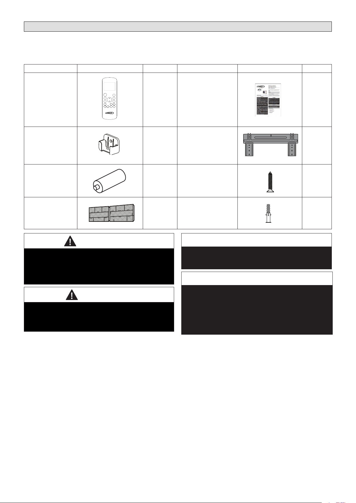
Included Parts
Package 1 of 1 contains the following:
1 - Assembled Indoor Unit
The assembled indoor unit will include the following items:
Parts Figure Quantity Parts Figure Quantity
ON/OFF
FP
TIMER
Wireless controller
MODE
ON
TEMP
TIMER
FAN/SLC
OFF
DIRECT
SLEEP
SWING
LED
FOLLOW
TURBO
CLEAN
1
Installation instruction,
user guide and warranty
1 ea.
Wireless control
holder with 2 mounting
1
screws
Batteries (AAA) 2
Return Air Filters
(Shipped installed in
indoor unit.)
WARNING
The clean Air Act of 1990 bans the intentional venting of
refrigerant (CFCs, HCFCs, and HFCs) as of July, 1992.
Approved methods of recovery, recycling or reclaiming
must be followed. Fines and/or incarceration may be
levied for non-compliance.
CAUTION
As with any mechanical equipment, contact with sharp
sheet metal edges can result in personal injury. Take
care while handling this equipment and wear gloves
and protective clothing.
Mounting plate
(shipped attached to the
1
back of the indoor unit)
Mounting plate securing
screws
5
Plastic screw anchors 5
IMPORTANT
All illustrations in this instruction are typical and do
not always represent the exact appearance of the
equipment.
IMPORTANT
The compressor in this unit contains PVE
oil (Polyvinylether). PVE oil is formulated for
hydrouorocarbon (HFC) refrigerants, such as HFC-
410A, which this system contains. While it may have
some miscibility properties with mineral-based oil and
POE oil (Polyolester), it is not recommended to mix PVE
oil with any other type of refrigerant oil.
2
Page 3
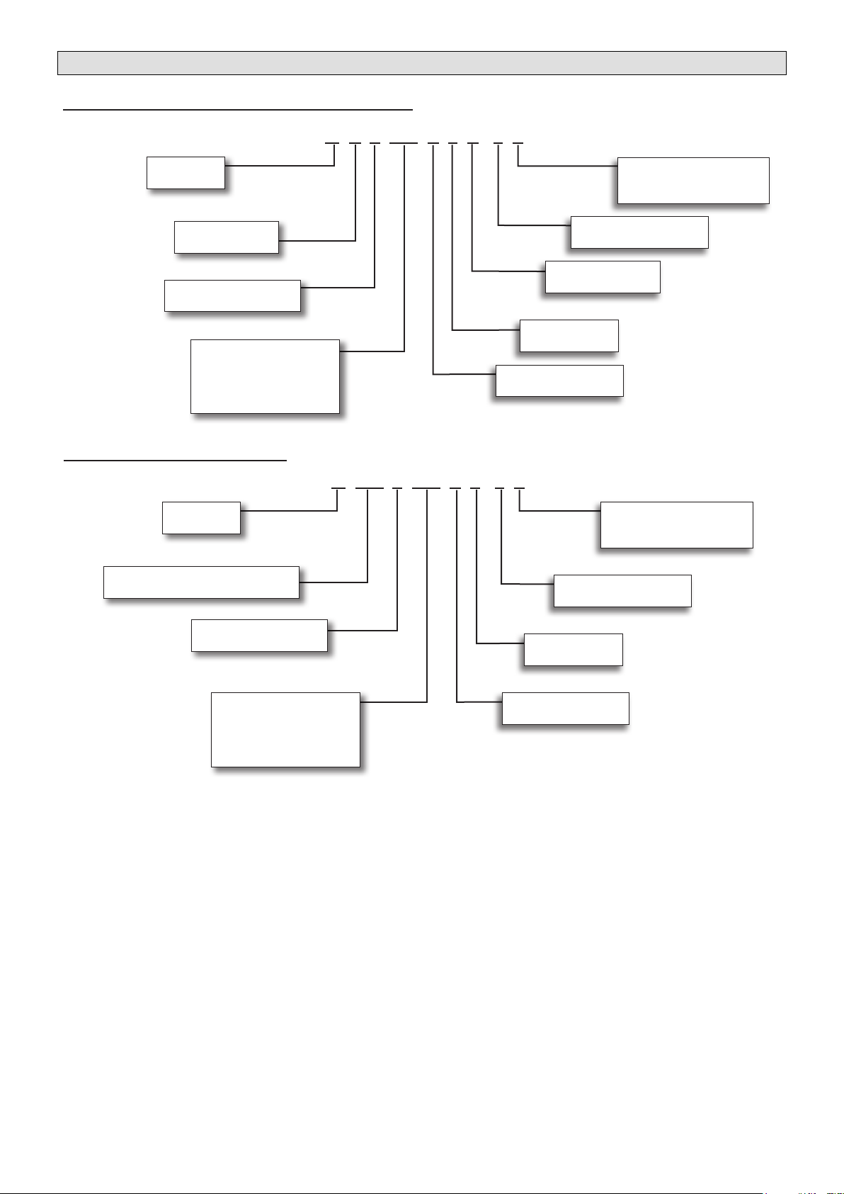
Model Number Identication
OUTDOOR SINGLE ZONE AIR CONDITIONER UNITS
M C A 009 S 4 S - 1 P
Series Type
M = Mini-Split
Unit Type
C = Air Conditioner
Major Design Sequence
A = First Generation
Nominal Cooling Capacity
009 = 0.75 ton
018 = 1.5 tons
024 = 2 tons
WALL-MOUNTED INDOOR UNITS
Series Type
M = Mini-Split
Unit Type
WC = Wall-Mounted Non-Ducted Unit
012 = 1 ton
Voltage
L = 115V-1 phase-60Hz
P = 208/230V-1 phase-60Hz
Minor Design Sequence
1 = 1st Revision
Refrigerant Circuits
S = Single Circuit
Refrigerant Type
4 = HFC-410A
Cooling Efciency
S = Standard Efciency
M WC A 009 S 4 - 1 P
Voltage
L = 115V-1 phase-60Hz
P = 208/230V-1 phase-60Hz
Minor Design Sequence
1 = 1st Revision
Major Design Sequence
A = First Generation
Nominal Cooling Capacity
009 = 0.75 ton
012 = 1 ton
018 = 1.5 tons
024 = 2 tons
Refrigerant Type
4 = HFC-410A
Cooling Efciency
S = Standard Efciency
3
Page 4
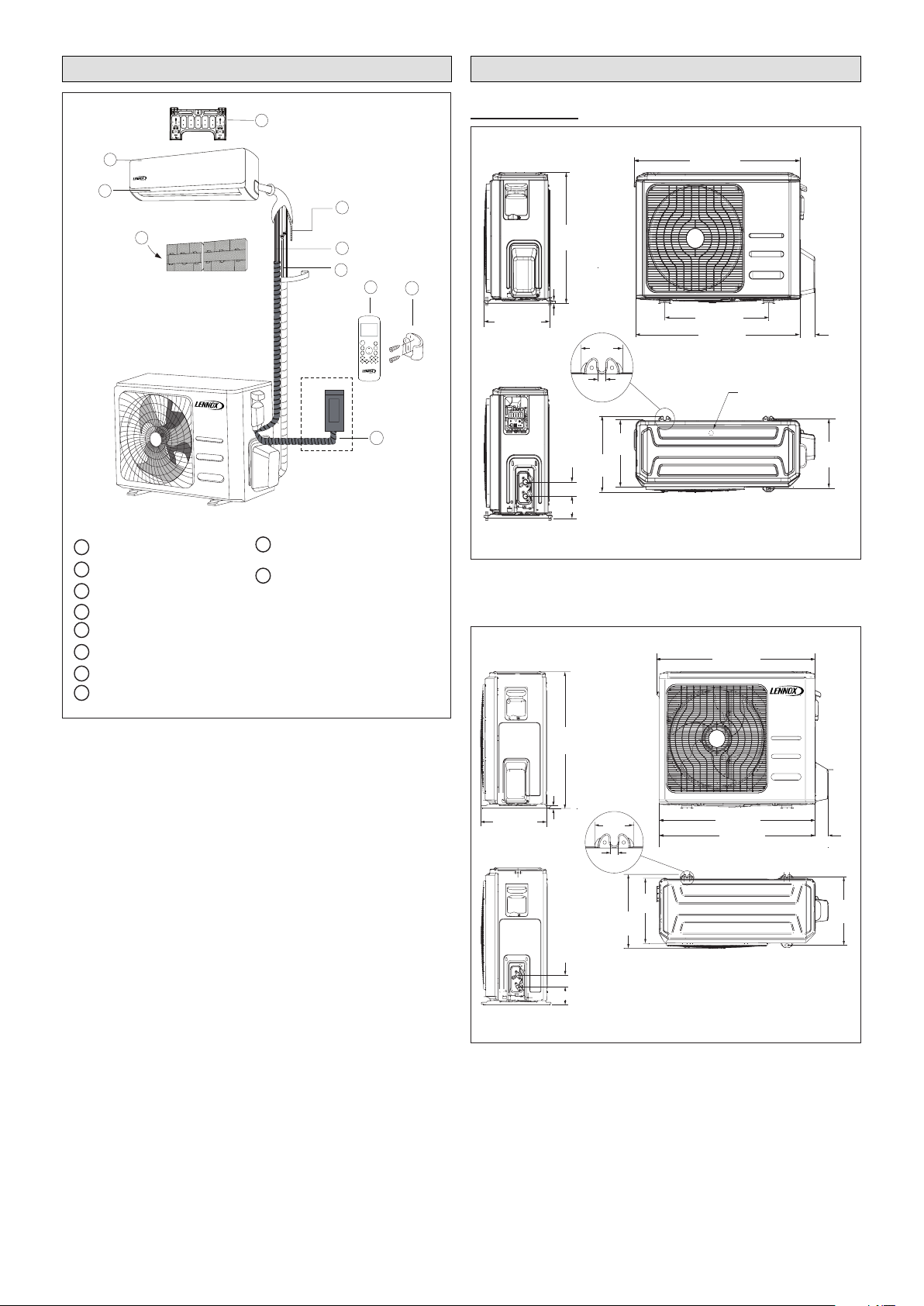
Typical System Components
1
2
3
4
6
7
8
9
10
5
Wall Mounting Plate
Refrigerant Piping
Signal Cable
Wireless Remote Control
Condensate Line
Louver
Wireless Remote Control Holder
Return Air Filters (2)
Front Panel
Outdoor Unit Power Cable
1
2
3
4
5
6
7
8
9
10
ON/OFF
TEMP
FP
TIMER
ON
TIMER
OFF
MODE
FAN/SLC
SLEEP
SWING
DIRECT
TURBO
CLEAN
LED
FOLLOW
19-1/8 (486)
2-3/4
(70)
11-7/8 (302)
21-7/8
(556)
30-3/8 (772)
30-5/8 (778)
2-1/2
(64)
1/2 (13)
1/2
(13)
MCA009S4S, MCA012S4S, MCA081S4S
BOTTOM VIEW
FRONT VIEWSIDE VIEW
SIDE VIEW
12-5/8
(322)
11-1/4
(286)
2-3/8 (60)
3-5/8 (92)
DRAIN HOLE (bottom of unit)
11-3/4
(298)
MCA024S4S
27-5/8
(702)
BOTTOM VIEW
FRONT VIEW
SIDE VIEW
SIDE VIEW
1/2
(13)
14-1/4 (362)
2-3/4
(70)
33-5/8 (854)
21-1/4 (540)
33-1/4 (845)
7-7/8
(200)
1-3/8 (35)
15
(381)
13-1/8
(333)
2-3/8 (60)
3-5/8 (92)
13-3/4
(349)
System Dimensions
Outdoor Units
Figure 1. Typical System Shown
Figure 2. 09, 12K and 18K Outdoor Unit Dimen-
sions - Inches (mm)
Figure 3. 24K Outdoor Unit Dimensions - Inches
(mm)
4
Page 5
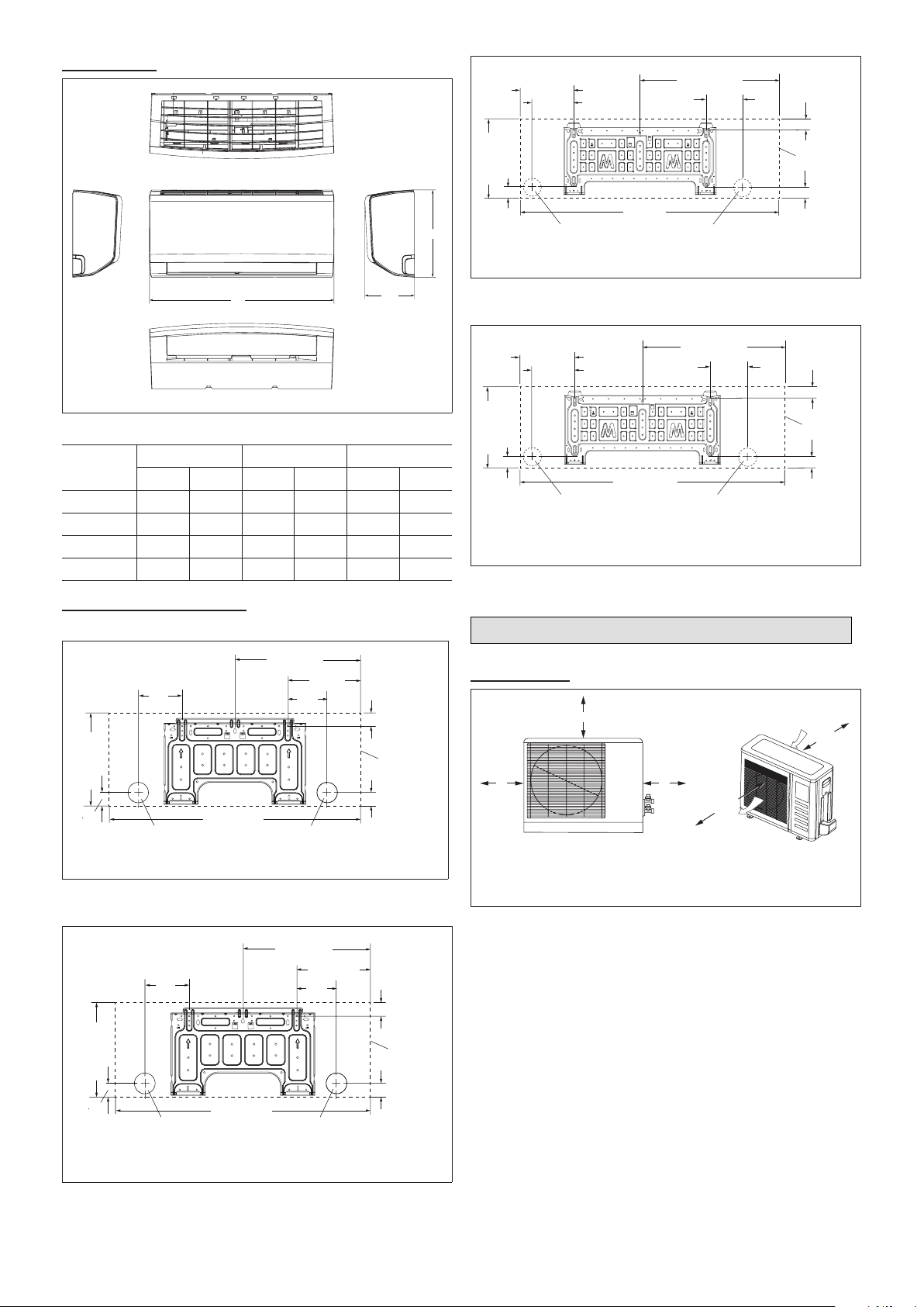
Indoor Units
A
B
C
TOP VIEW
FRONT VIEW
BOTTOM VIEW
SIDE VIEWSIDE VIEW
24 (610)
Air Outlet
Air Inlet
24
(610)
12
(305)
79
(2007)
1
12
(305)
1
Minimum rear clearance can be 6 inches (152 mm) when mounted on brackets
and with no obstructions on the other three sides.
MWCA018S4
6-3/4 (171)
2-1/4
(57)
12-1/2 (318)
5-3/8 (137)
Left Rear Hole
2-1/2 in. (64 mm)
diameter
38 (965)
20-3/8 (518)
5-5/8
(143)
Right Rear Hole
2-1/2 in. (64 mm)
diameter
2-1/4 (57)
Wall-Mount
Unit Outline
2-3/8 (60)
Figure 7. 18K Indoor Unit Wall Plate Dimensions -
Inches (mm)
Figure 4. Indoor Unit Dimensions - Inches (mm)
Size
9K 29-5/8 752 11-3/8 289 8-5/8 219
12K 32-3/4 832 11-3/4 298 8-3/4 222
18K 39-1/8 994 12-1/2 318 9-7/8 251
24K 44 1118 13-1/4 337 10-1/4 260
A B C
in. mm in. mm in. mm
Indoor Unit Wall Mounts
MWCA009S4
11-3/8 (289)
1-7/8
(48)
4
(102)
Left Rear Hole
2-1/2 in. (64 mm)
diameter
28-1/2 (724)
13-3/4 (349)
5-3/8
(136)
Right Rear Hole
2-1/2 in. (64 mm)
diameter
7 (178)
1-1/2 (38)
Wall-Mount
Unit Outline
2 (51)
MWCA024S4
8-5/8 (219)
1-7/8
(48)
13-1/4 (337)
2-1/2 in. (64 mm)
6-7/8 (175)
42-1/2 (1080)
Left Rear Hole
diameter
21-3/4 (553)
11-7/8
(301)
Right Rear Hole
2-1/2 in. (64 mm)
diameter
2-1/8 (54)
Wall-Mount
Unit Outline
1-7/8 (48)
Figure 8. 24K Indoor Unit Wall Plate Dimensions -
Inches (mm)
System Clearances
Outdoor Unit
Figure 5. 9K Indoor Unit Wall Plate Dimensions -
Inches (mm)
MWCA012S4
7-1/2
(191)
11-3/4 (298)
1-3/4
(44)
Figure 6. 12K Indoor Unit Wall Plate Dimensions -
31-5/8 (803)
Inches (mm)
Left Rear Hole
2-1/2 in. (64 mm)
diameter
16-3/4 (425)
9-1/8 (232)
5
(127)
Right Rear Hole
2-1/2 in. (64 mm)
diameter
1-3/4 (44)
Wall-Mount
Unit Outline
1-3/4 (44)
Figure 9. Outdoor Unit Clearances - Inches (mm)
5
Page 6
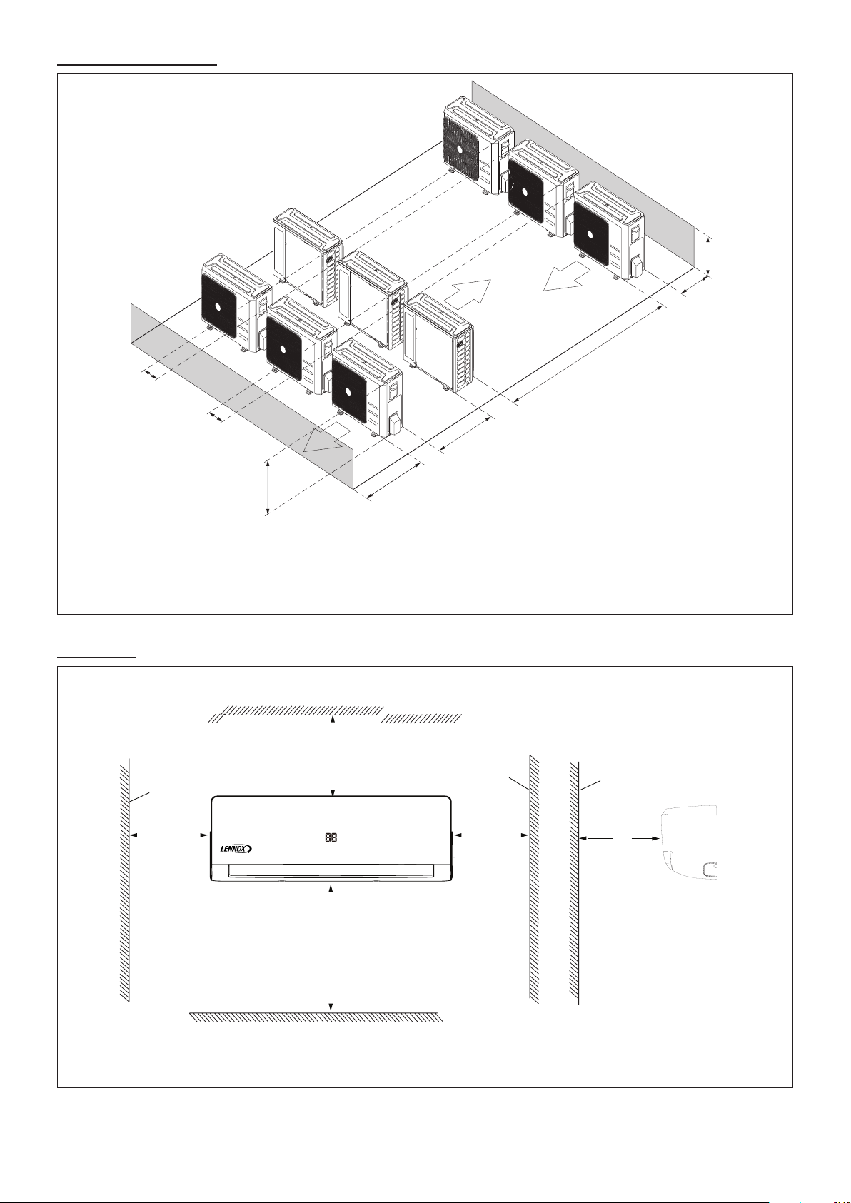
Multiple Outdoor Units
FRONT VIEW
Wall
Vertical Clearance - Clearance to Floor -
72 inches (1829 mm) Minimum
96 inches (2438 mm) Recommended
5”
(127 mm)
Minimum
6” (152 mm)
Minimum Clearance
Ceiling
Wall
Floor
5”
(127 mm)
Minimum
59”
(1499 mm)
Minimum
SIDE VIEW
Any Object
10 (254)
(Minimum)
10 (254)
(Minimum)
AIR
FLOW
118 (2997)
(Minimum)
Height of
Wall (C)
Unit to
Wall (B)
CLEARANCE NOTES FOR MULTIPLE UNITS:
If the height of the wall (C) is less than or equal to the height of the smallest unit (A), the distance from the unit to the wall (B) must be a minimum of 10 inches (254 mm).
If 1/2 the height of the unit (A) is less than the height of the wall (C), the distance from the unit to the wall (B) must be a minimum of 12 inches (305 mm).
If the height of the wall (C) is greater than the height of the unit (A), the distance from the unit to the wall (B) must be a minimum of 20 inches (508 mm).
Indoor Unit
24 (610)
(Minimum)
Unit
Height (A)
AIR
FLOW
60 (1500)
(Minimum)
Figure 10. Multiple Outdoor Unit Clearances - Inches (mm)
Figure 11. Indoor Unit Clearances - Inches (mm)
6
Page 7

Torque Requirements for Caps and
Fasteners
When servicing or repairing HVAC components, ensure
the fasteners are appropriately tightened. “Table 1. Torque
Requirements” on page 7 provides torque values for
fasteners.
IMPORTANT
Only use Allen wrenches of sufcient hardness (50Rc -
Rockwell scale minimum). Fully insert the wrench into
the valve stem recess.
Service valve stems are factory-torqued from 9 ft.-lbs.
(12 N*m) for small valves, to 25 ft.-lbs. (34 N) for large
valves) to prevent refrigerant loss during shipping and
handling. Using an Allen wrench rated at less than 50Rc
risks rounding or breaking off the wrench, or stripping
the valve stem recess.
See the Lennox Service and Application Notes C-08-1
for further details and information.
Table 1. Torque Requirements
Parts
Service valve cap 8 ft.-lb. 11
Sheet metal screws 16 in.-lb. 2
Machine screws #10 27 in.-lb. 3
Compressor bolts 7 ft.-lb. 10
Gauge port seal cap 8 ft.-lb. 11
Recommended Torque
U.S. Newton-Meter- N
DO
• Place the unit so that it is not exposed to direct sunlight.
• Ensure the structural wall can support the weight of
the unit.
• Select a location where condensate line will have the
shortest run to a suitable drain per local codes.
• Allow sufcient space around unit for proper operation
and maintenance.
• Install unit a minimum of 3 feet (1m) away from any
antenna, power cord (line) radio, telephone, security
system, or intercom. Electrical interference and radio
frequencies from any of these sources may affect operation.
• Be sure to instruct customers how to properly operate
the unit (especially maintenance of air lter, and operation procedure) by having them carry out operations
themselves while looking at the manual provided with
the controller.
Determining Wall Mounting Plate Location
Left piping
Left back piping
Right back piping
Right piping
Figure 12. Determining Exit Locations
Indoor Unit Installation
CAUTION
In order to avoid injury, take proper precaution when
lifting heavy objects.
Unit Placement Considerations
AVOID
Do not install the unit in the following locations:
• Areas exposed to petrochemicals or petrochemical
products.
• Areas exposed to salt or other corrosive materials or
caustic gases.
• Areas exposed to extreme voltage variations (such as
factories.
• Tightly enclosed areas that may impede service of the
unit.
• Areas exposed to fossil fuels (such as oil or gas in
kitchens).
• Areas exposed to strong electromagnetic forces.
• Areas exposed to acids or alkaline detergents.
1. Remove the wall mounting plate from the back of the
indoor unit.
2. Determine the best exit location for utility bundle
(line set, condensate line and wiring). See the
following section concerning wall sleeve installation
instructions.
3. Position the wall mounting plate on the wall so that,
when installed, the unit will be at least 6 inches (152
mm) from the ceiling and 5 inches (127 mm) from the
wall on either side. The wall mounting plate must be
level side-to-side.
4. Use the wall mounting plate as a template to
determine the exit point for utility bundle. Mark the
wall to facilitate drilling hole for utility bundle.
Installation of Wall Mounting Plate
Install the wall mounting plate (see “Figure 5. 9K Indoor
Unit Wall Plate Dimensions - Inches (mm)” on page 5)
so that it is correctly positioned horizontally and vertically.
The indoor unit must be installed level on the wall to allow
proper condensate drainage.
1. Use a carpenter’s level or measuring tape to verify the
wall mounting plate is horizontally level.
2. Secure the wall mounting plate to the wall using the
provided screws and screw anchors.
NOTE: It is important to use all screws provided to secure
the wall mounting plate to the wall. Additional holes
may be drilled through the metal wall mounting
plate to better secure wall plate. Field-provided
anchors/xings may be required depending on
7
Page 8

wall construction. Use the appropriate type of
anchors for the application.
3. The wall mounting plate must be installed ush
against the wall so that the indoor unit will be ush
after installation. Any space between the wall and unit
will cause noise and vibration.
4. The wall mounting plate must be installed horizontally
level on the wall.
Installation of Wall Sleeve
The utility bundle may be routed out of the back of the unit
or out either side. If the bundle is to be routed out the back
through an external wall, use a eld-provided wall sleeve
to protect the utility bundle.
NOTE: If the utility bundle will be routed out the side of the
indoor unit and up the wall above a false ceiling,
continue to the next section.
1. Prior to making the hole and installing the wall sleeve
for the utility bundle, check to ensure that there are
no other utilities located in the wall behind the hole
location.
2. Cut a hole in the wall using a suitable hole saw. Hole
should be at a slight downward slant - 3/16” to 3/8”
toward the outdoor side.
3. Measure the thickness of the wall from the inside
edge to the outside edge and cut the eld-provided
wall sleeve at a slight angle 1/4” (6 mm) shorter than
the thickness of the wall.
Installation of Indoor Unit on Wall Mounting Plate
1. A length of eld-provided exible condensate piping
should be connected to the drain prior to securing the
unit to the wall mounting plate.
2. If the factory-provided refrigerant piping connections
and eld-provided exible condensate piping are long
enough to enable nal eld connections after unit is
installed on wall mounting plate, use eld-provided
tape to bundle them together.
3. The utility bundle may be routed out of the back of
the unit or out either side. If the bundle is to be routed
out the back through an external wall, feed the utility
bundle through the wall sleeve. If the utility bundle is
to be routed out of the side of the indoor unit and up
an inside wall, carefully form the utility bundle so that
it makes a gentle 90° turn.
4. Align the back of the indoor unit with the hooks at the
top of the wall mounting plate. Move the unit from side
to side to make sure that it settles securely.
5. The bottom of the unit can be lifted to facilitate
refrigerant piping and condensate drain connections,
if necessary.
HOOKS AT TOP
OF MOUNTING
BRACKET
TEMPORARY
SPACER
(To facilitate
connections)
INSIDE
OUTSIDE
Typical
installation
procedure
shown.
Figure 13. Boring Hole for Wall Sleeve
USE SUITABLE TOOL TO CUT PVC FOR WALL
SLEEVE AT SLIGHT ANGLE AS SHOWN.
Figure 14. PVC Wall Sleeve Installation
NOTE: When passing bundled services through an
exterior brick or concrete wall, protect the
copper pipes and wiring from the effects of these
construction materials by using a sleeve made
of suitable material. The integrity of copper pipe
and wiring can deteriorate when exposed to these
construction materials.
Figure 15. Secure Unit to Wall Mounting Plate
Indoor Unit Condensate Piping Connections
IMPORTANT
Make sure that drain piping is properly routed and
insulated to prevent both leaks and condensation.
1. Use a eld-provided hose clamp to secure the drain
line stub on the side of the cabinet to a eld-supplied
1-inch (25 mm) drain line.
NOTE: Take care not to over-tighten the hose clamps this
may damage the drain line stub.
NOTE: Connection between stub and drain line must be
watertight. Apply non-hardening plumbing joint
compound if needed to ensure a watertight seal.
2. Conrm proper slope (not less than 1/4 inch per foot
(18 mm per meter) and routing of condensate lines to
ensure moisture is drained away from the indoor unit.
3. Drain should be as short as possible and should
not have any droops or kinks that would restrict
condensate ow and shall be approved resistant pipe.
There must be a 2-inch (51 mm) space between the
end of the condensate drain and the nal termination
point (ground, open drain, etc.) to ensure that the line
will drain freely.
4. After the system installation is complete, the
condensate drain line must be checked for leaks
and proper drainage. If a eld-provided condensate
8
Page 9

pump has been installed, it must be checked to
12 in
305 mm
24 in
610 mm
24 in
610 mm
12 in
305 mm
NOTE - Minimum clearances shown.
ensure proper operation. This check is part of the
start-up process which must be done by the installing
contractor.
IMPORTANT
Drain should have a slope of at least ¼ inch per foot and
should be approved corrosion-resistant pipe. You must
conrm operation of every drain and pump in the system
as part of the commissioning procedure.
CORRECT
Make sure there are no
kinks or dent in drain
hose to ensure proper
drainage.
Figure 16. Condensate Line
Outdoor Unit Installation
• Choose a location where the hot air discharged from
the unit or the operation noise will not be a nuisance
to neighbors.
• Avoid installing the outdoor unit near a bedroom or
other places where noise may cause a problem.
• There must be sufcient space to carry the unit into
and out of the site.
• There must be unobstructed air ow around the air
inlet and the air outlet.
• The unit must not be installed in areas where a ammable gas leak may occur.
• Install the outdoor unit a minimum of 3 feet (1m) away
from any antenna, power cord (line), radio, telephone,
security system, or intercom. Electrical interference
and radio frequencies from any of these sources may
affect operation.
• Since water drains from the outdoor unit during various stages of operation, do not place anything which
may be damaged by moisture under the unit.
Direct Sunlight and Rain Protection
• If the outdoor unit is subjected to prolong exposure to
direct sunlight with temperatures over 100°F (38°C) a
canopy is recommended as illustrated in “Figure 18.
Outdoor Unit on Pedestal and Protective Canopy”or
“Figure 19. Dog House-Style Shelter” on page 9.
Placement Considerations
Consider the following when positioning the unit:
• In coastal areas or other places with salty atmosphere
of sulfate gas, corrosion may shorten the life of the
unit. In coastal areas, the coil should be cleaned with
potable water several times per year to avoid corrosive buildup (salt).
• Some localities are adopting sound ordinances based
on the unit’s sound level registered from the adjacent property, not from the property where the unit is
installed. Install the unit as far as possible from the
property line.
• When possible, do not install the unit directly outside
a window. Glass has a very high level of sound transmission.
• Install unit level.
Building Structure
Protective canopy
Pedestal
(stand)
Air Outlet
Side View
12 in
305 mm
Air Inlet
Protective canopy
24 in
610 mm
Front View
Pedestal
(stand)
Figure 18. Outdoor Unit on Pedestal and Protective
Canopy
Ground
Level
Figure 17. Install Unit Level
• Choose a place solid enough to bear the weight and
vibration of the unit, where the operation noise will not
be amplied.
Figure 19. Dog House-Style Shelter
9
Page 10

IMPORTANT
The construction of a canopy or shade is necessary
because of an ambient limit control set to 122°F (50°C)
to protect the electronics. If the outdoor unit is placed in
direct sunlight it is possible that the limit may activate
and shut down the unit.
• Place unit away from overhanging roof lines which
would allow water or ice to drop on, or in front of, coil
or into unit. Construct a canopy as illustrated in “Figure 18. Outdoor Unit on Pedestal and Protective Canopy”.
Buried Refrigerant Pipe Protection
• All refrigerant lines must be insulated regardless of if
it is buried.
• In addition to insulating each line of piping, buried
lines must rest inside a sealed, watertight conduit.
• The conduit must be designed so it cannot collect and
retain water.
Securing the Outdoor Unit
Slab or Roof Mounting
Install the unit a minimum of 4 inches (102 mm) above
the roof or ground surface to avoid debris build-up around
the unit. Place the unit above a load bearing wall or area
of the roof that can adequately support the unit. Consult
local codes for rooftop applications.
CAUTION
Roof Damage!
This system contains both refrigerant and oil. Some
rubber roong material may absorb oil. This will cause
the rubber to swell when it comes into contact with oil.
The rubber will then bubble and could cause leaks.
Protect the roof surface to avoid exposure to refrigerant
and oil during service and installation. Failure to follow
this notice could result in damage to roof surface.
Four Field-Provided
Anchor Bolts
Figure 21. Securing Outdoor Unit to Rails
Securing Outdoor Unit to Hanging Brackets
If the outdoor unit is installed on eld-provided wall
mounting brackets, use lag bolts or equivalent to secure
the outdoor unit to the bracket. Minimum rear clearance
can be reduced to 6 inches (152 mm) when mounted
on brackets and with no obstructions on the other three
sides. Allow for moisture disposal when placing units
above one another.
6 in
152 mm
Air Inlet
Air Outlet
Figure 22. Securing Outdoor Unit to Brackets
Refrigerant Piping Connections
Securing Outdoor Unit to Slab, Frame, or Rails
If the outdoor unit is installed on a eld-provided slab or
frame, use lag bolts or equivalent to secure the outdoor
unit to the slab or frame.
Four Field-provided Anchor Bolts
Figure 20. Securing Outdoor Unit to Slab
Field piping consists of two copper lines connecting the
outdoor unit to the indoor unit. “Table 3. Refrigerant Piping
and Indoor Unit Connection Sizes” on page 11 lists
the connection sizes. The connections are made using
the provided brass are nuts at the end of the refrigerant
piping connections.
1. Choose the correct pipe sizes for your application
using “Table 3. Refrigerant Piping and Indoor Unit
Connection Sizes” on page 11.
2. Conrm that you are using the correct diameter piping.
3. Determine the necessary piping length required for
the application.
4. Cut the selected pipes with a pipe cutter. Make the
cuts at and smooth as illustrated in “Figure 23.
Cutting Piping”.
10
Page 11

90
Lean
Crude
Burr
o
Table 3. Refrigerant Piping and Indoor Unit
Connection Sizes
Size
(Btuh)
9K 1/4 3/8
12K 1/4 1/2
18K 1/4 1/2
24K
Liquid Line
in.
3/8 5/8
Suction Line
in.
Figure 23. Cutting Piping
5. Insulate the copper piping.
6. Insert a are nut onto each pipe before aring.
7. Use “Table 2. Flaring Pipe” to properly are the pipe.
Table 2. Flaring Pipe
Flare Dimension
Pipe Diameter
1/4” 8.3 8.7
3/8” 12.0 12.4
1/2” 15.4 15.8
5/8” 18.6 19.1
3/4” (22.9) 22.9 23.3
A (mm)
Min Max
Flare Shape
90
A
+
°
-
4
45
°
R0.4~0.8
8. After aring the pipe, temporarily sealed pipe ends
with adhesive tape to avoid contaminants from
entering the pipes.
9. The seal on the unit refrigerant piping connections
should remain in place until the last possible moment.
This will prevent dust or water from getting into the
refrigerant piping before it is connected.
10. CAREFULLY adjust refrigerant piping connections to
suit the application.
11. Slowly loosen one of the are nuts to release the
factory nitrogen charge from the indoor units only.
12. Remove the are nuts from the connections on the
unit and discard the seal from each of the piping
connections.
13. Slide the are nuts onto the ends of the eld-provided
refrigerant piping before using a suitable aring tool to
are the end of the copper pipe.
14. Apply recommended HFC-410A refrigerant lubricant
to the outside of the ared refrigerant lines.
15. Align the threaded connections with the
ared refrigerant lines. Tighten the are nuts
lightly at rst to obtain a smooth match as
illustrated in “Figure 24. Making Connections
(Male to Female Connection)”.
11
A
CANT ON THE OUTSIDE OF
THE FLARE
MALE FLARE
CONNECTION
B
Figure 24. Making Connections
(Male to Female Connection)
16. Once snug, continue another half-turn on each nut
which should create a leak-free joint. A torque wrench
may be used to tighten are nuts using “Table 4. Flare
Nut Torque Recommendations”.
17. After refrigerant piping has been installed and checked
for leaks, apply insulation over all ared connections.
IMPORTANT
Always use two wrenches when tightening are nuts to
avoid twisting refrigerant piping. DO NOT over-tighten
are nuts.
TORQUE WRENCH
TO INDOOR
UNIT
TO OUTDOOR UNIT
BACKUP
WRENCH
Figure 25. Tighten Flare Nut
Table 4. Flare Nut Torque Recommendations
Outside
Diameter
Inches
1/4 15 ft.-lb. (20 N) 1/4 turn
3/8 26 ft.-lb. (35 N) 1/2 turn
1/2 41 ft.-lb. (56 N) 7/8 turn
5/8 48 ft.-lb. (65 N) 1 full turn
Recommended
Torque
No torque wrench available
Finger tighten and use an
appropriately sized wrench to
turn an additional:
IMPORTANT
Do not allow for excess length of line sets to be left
rolled up as part of the required, or in general. This will
also cause additional performance issues.
Page 12

IMPORTANT
OUTDOOR UNIT
OUTDOOR UNIT
INDOOR UNIT
INDOOR UNIT
Maximum Line Set
Length
Maximum Line Set
Length
Maximum
Elevation -
Outdooor
Unit BELOW
Indoor Unit
Maximum
Elevation -
Outdooor
Unit ABOVE
Indoor Unit
Minimum Line Set
Length - 10 ft. (3m)
Minimum Line Set
Length - 10 ft. (3m)
Outside Unit BELOW Indoor Unit Outside Unit ABOVE Indoor Unit
Do not over-tighten a ared joint. Flared connections should always be accessible and must be insulated to prevent
condensation.
Figure 26. Indoor and Outdoor Unit Elevation Relationships
Table 5. Line Set Guide
Each system size has a line set length and vertical elevation parameters.
Line Set Diameters (in.)
System
Size (KBtu)
009 1/4 3/8 82 (25) 33 (10) 82 (25)
012 1/4 1/2 82 (25) 33 (10) 82 (25)
018 1/4 1/2 98 (30) 66 (20) 98 (30)
024 3/8 5/8 98 (30) 66 (20) 98 (30)
Liquid Gas
Maximum Elevation
Outdoor Unit BELOW
Indoor Unit - Feet
(Meter)
Maximum
Elevation
Outdoor Unit
ABOVE Indoor
Unit - Feet (Meter)
Maximum Line
Set Length -
Feet (Meters)
Additional Refrigerant for
greater than 25 Foot Line Set
Lenght
For the additional charging, we
recommend 0.161 oz. for 1/4”
liquid line and 0.322 oz. for 3/8”
liquid line per foot.
Adding Refrigerant for Longer Line Set
The outdoor unit is factory-charged with refrigerant
to accommodate up to 25 feet of line set. For adding
additional refrigerant for longer line sets, see “Table 5.
Line Set Guide”.
Be sure to add the proper amount of additional refrigerant.
Failure to do so may result in reduced performance.
Leak Test and Evacuation
Air and moisture remaining in the refrigerant system will
have undesirable effects as indicated below:
• Pressure in the system rises.
• Operating current rises.
• Cooling or heating efciency drops.
• Moisture in the refrigerant circuit may freeze.
• Water may lead to corrosion of parts in the refrigeration system.
The line set between the indoor and outdoor units
must be leak tested and evacuated to remove any noncondensables and moisture from the system.
Leak Test
Use the following procedure to test for system leaks:
1. Connect the manifold gauge set and dry nitrogen gas
cylinder to the suction and gas service ports.
2. Open valve on nitrogen cylinder.
3. Pressurize the system per the pressure test
specications in “Table 6. Pressure Test
Specications”.
4. Check that the system pressure remains stable. If
there is any movement check system for leaks.
5. After the system is found to be free of leaks:
• Close valve on nitrogen cylinder.
• Relieve the nitrogen pressure by: loosening the
charge hose connector at the nitrogen cylinder.
• When the system pressure is reduced to normal,
disconnect the hose from the cylinder.
Table 6. Pressure Test Specications
Bar Psig kPa Duration
1 3 44 303 Minimum of 10 minutes
2 15 220 1517 Minimum of 10 minutes
3 32 470 3241 Minimum of 10 minutes
1 hour. Stress test to prove the
4 45 650 4482
5 32 470 3241
Use only oxygen-free nitrogen (OFN).
integrity of the complete installation.
24 hours. Lower system pressure
test, after conrmation No. 4 was
successfully completed.
IMPORTANT
12
Page 13

Triple Evacuation Procedure
Terminal Block
208/230V Outdoor Unit
Terminal Block
From Power
Supply
Terminal Block
208/230V Indoor Unit
Outdoor Unit Indoor Unit
3
2
L1
L2
1
Y/G
1
3
Y/G
Y/G
115VAC Outdoor Unit
Terminal Block
From Power
Supply
Terminal Block
115VAC Indoor Unit
Outdoor Unit Indoor Unit
3
2
L
N
1
Y/G
1
3
Y/G
Y/G
*
*
18 and 24K
unit has
five terminal
sets.
A Micron or Torr gauge must be used for this procedure.
1. Discharge the oxygen-free nitrogen and evacuate the
system to a reading of 8000 Microns (8 Torr) using all
service valves.
2. Break the vacuum by allowing nitrogen into the port
connections (liquid and gas line pipes) until a positive
pressure is achieved.
3. Evacuate the system to a reading of 5000 Microns (5
Torr).
4. Break the vacuum by allowing nitrogen into the port
connections (liquid and gas line pipes) until a positive
pressure is achieved.
5. Evacuate the system to a minimum reading of 500
Microns (0.5 Torr).
6. For a moisture-free system, ensure the vacuum is
held without movement for a minimum of 4 hours.
7. If vacuum fails to hold, carry out steps 2 through 6
until vacuum holds.
Wiring Connections
In the U.S.A., wiring must conform with current local
codes and the current National Electric Code (NEC).
In Canada, wiring must conform with current local codes
and the current Canadian Electrical Code (CEC).
Outdoor Unit
• Refer to unit nameplate for minimum circuit ampacity
and maximum over-current protection size.
• Make all electrical power wiring connections at the
outdoor unit.
• Be sure to reattach all electrical box covers after connections are complete.
Indoor Unit
• Indoor unit is powered by the outdoor unit.
• Communication, power and ground wiring - Use one
stranded 3-conductor with ground wire.
• See “Table 7. Single Zone Installation Wiring Require-
ments” on page 14 for wiring requirements.
NOTE: When installing a condensate pump the line voltage
will have to be broken by using the condensate
wiring or through the use of an external relay or
contactor.
IMPORTANT
All illustrations listed are typical wiring diagrams. Refer
to the wiring diagram on the unit for actual wiring.
Terminal block
WARNING
Electric Shock Hazard. Can cause injury or death. Unit
must be rounded in accordance with national and local
codes.
Line voltage is present at all components when unit is
not in operation. Disconnect all remote electric power
supplies before opening access panel. Unit may have
multiple power sources.
CAUTION
All terminal connections must be made as illustrated
in the following diagrams. Improperly connected wiring
could damage unit or cause communication errors
between indoor and outdoor units.
Figure 27. Indoor Unit Terminal Block
Cover
Screw
Cable Clamp
The wiring diagram is located
on the inside of the indoor unit’s
terminal block cover.
Figure 28. Single Zone Wiring
13
Page 14

IMPORTANT
This unit must be properly grounded and protected by a circuit breaker. The ground wire for the unit must not be
connected to a gas or water pipe, a lightning conductor or a telephone ground wire.
Do not connect power wires to the outdoor unit until all other wiring and piping connections have been completed.
Do not install the unit near a lighting appliance that includes a ballast. The ballast may affect remote control operation.
Table 7. Single Zone Installation Wiring Requirements
Systems and Terminal
Designations
Indoor to Outdoor Wiring
(Communication/Power)
1, 2, 3 and GND
System Capacity System Voltage
12K 115VAC 4
Number of
Conductors
Wire Type Wire Gauge / MCA
16AWG
Outdoor to Main Power
L, N and GND
Indoor to Outdoor Wiring
(Communication/Power)
1, 2, 3 and GND
Indoor to Outdoor Wiring
(Communication/Power)
1, 2, 3 and GND
Outdoor to Main Power
L1, L2 and GND
Indoor to Outdoor Wiring
(Communication/Power)
1, 2, 3 and GND
Outdoor to Main Power
L1, L2 and GND
MCA = Minimum Circuit Amps
12K 115VAC 3 14AWG / 15A
09K 208/230VAC 4 16AWG / 10A
12K 208/230VAC 4 16AWG / 11A
09K and 12K 208/230VAC 3 16AWG / 9A
18K and 24K 208/230VAC 4 16AWG
18K and 24K 208/230VAC 3 14AWG / 18A
Stranded and
unshielded
14
Page 15

Wiring Diagrams (Outdoor Units)
BROWN
3
2
L1
L2
BLACK
1
Y/G
AMBIENT TEMP. SENSOR
CONDENSER TE MP SENS OR.
Y/G
Y/G
Y/G
U
V
W
BLUE
RED
BLACK
Y/G
Y/G
Indoor Unit
T5
T3
T4
COMPRESSOR
Y/G
DC-FAN
CN 7
3
B LUE
B R OWN
BLACK
3
2
L
N
R E D
B LUE
Y/G
1
Y/G
AMBIENT TEMP. SENSOR
DIS CHARG E TEMP. SENSOR
CN 21
.
Y/G
Y/G
Y/G
CN4_1
CN4_2
CN4_3
CN4_4
REACTOR
CAPACITOR
BROWN
BROWN
BLACK
BLACK
BLACK
W
V
RED
BLUE
U
CN 1A
CN 3
CN 1
CN 2
CN 16
CN 50
CN 30
CN 29
CN 28
OUTDOOR
MAIN
PCB
T5 T3 T4
Figure 29. 09 and 12K - 208/230VAC Outdoor Unit Wiring Diagram
Figure 30. 12K - 115VAC Outdoor Unit Wiring Diagram
15
Page 16

BLUE
BLACK 3
Y/G
Y/G
BROWN 1
BLUE L2
RED
BLUE
RED
BLACK
V
W
U
COMPRESSOR
Y/G
DISCHARGE TEMP. SENS OR
CN 17
CN 21
U
V
W
.
OUTDOOR
MAIN
PCB
CN 414
AMBIENT TEMP. SENSOR
DC-FAN
Y/G
CN 6
CN 7
CN 8 CN 2
S
Y/G
1
2
L2
L1
3
CN 3
L1
L2
Y/G
3
Figure 31. 18K and 24K 208/230VAC Outdoor Unit Wiring Diagram
Wiring Diagrams (Indoor Units)
FOR REMOTE ON/OF
S5
MODE
FACTORY SETTING
2
3
1
FOR SETTING NETADDRESS
E
D
ENC2+S1
C
B
CODE
NETADDRESS
REMOTE ON/OFF OFFREMOTE ON/OFF ON
0
1
ON
F
2
3
4
5
6
A
7
9
2
1
8
0~F 0~F 0~F 0~F
0~15
3
MAIN CONTROL BOARD
1
0
ON
F
2
E
3
D
4
C
5
B
6
A
7
9
1
8
16~31 32~47 48~63
0
1
ON
F
2
E
3
D
4
C
5
B
6
A
7
9
2
8
D
C
2
1
F
E
B
A
CN10A
0
1
7
9
8
2
6
3
~
4
5
M
8
3
ON
1
2
DI SP LA Y BOARD
CN2 (C N201
)
Wired Controller
M
CN3 (C N301
)
OPTIONAL
OPTIONAL
Programmable
Wired Controller
Note: The programmable wired
controller and LVM use the same
port CN403.
NOTE: COMPONENT IN
DASH LINE IS OPTIONAL
OR FIELD WIRING
5
4
(T2)
ADAPTER BOARD
5
CN 50 1
CN 40 2
(T1)
CN 403
X Y E
YELLOW
BROWN
To LVM
Comm.Bus
RED
Figure 32. 09K and 12K Indoor Unit Wiring Diagram (115 and 208/230VAC)
16
Page 17

FOR REMOTE ON/OF
CN6
CN3
CN2
RED
CN_TO
TRANSFORMER
CN5
INDOOR MOTOR
INDOOR UNIT
TO OUTDOOR UNIT
CN_TIN
Y/G
BLUE
5-WAY TERMINAL
MAIN BOARD
WIRING DIAGRAM
2
1
1(2)3(4)
1(2)3(4)
2(4)
2
1
2
1
2
1
2
1
2
1
CN_L1
M
~
2
WHITE
CN_N1
CN_S
FAN CAPA CITOR BOARD
PC1_1
PC2_1
1 2 3 4 5
SWING MOTOR
M
5
1 2 3 4 5
CN10
T1_room
T2_pipe
CN4
3
WHITE
WHITE
3
1
2
1
2
3
0
8
4
1
2
3
5
6
7
C
9
A
B
D
E
F
1
2
ON
0
8
4
1
2
3
5
6
7
C
9
A
B
D
E
F
1
2
ON
0
8
4
1
2
3
5
6
7
C
9
A
B
D
E
F
1
2
ON
0
8
4
1
2
3
5
6
7
C
9
A
B
D
E
F
1
2
ON
ENC2+S1
0~F 0~F 0~F 0~F
NETADDRESS
CODE
0~15
16~31 32~47 48~63
FOR SETTING NETADDRESS
DISPLAY BOARD
8
Wired Controller
OPTIONAL
ADAPTER BOARD
CN3(CN301)
CN501
CN403
X Y E
To LVM
Comm.Bus
Y
ELL
OW
BROWN
R
E
D
5
5
Programmable
Wired Co ntroller
OPTIONAL
4
Note: The prog rammable wi red
controller and LV M use the same
port CN403.
CN2(CN201)
CN402
NOTE: COMPONENT IN
DASH LINE IS OPTIONAL
OR FIELD WIRING
S5
FOR REMOTE ON/OF
FACTORY SETTING
MODE
REMOTE ON/OFF OFFREMOTE ON/OFF ON
S5
MODE
FACTORY SETTING
REMOTE ON/OFF OFFREMOTE ON/OFF ON
M
M
5
SWING MOTOR1
NOTE: COMPONENT IN
DASH LINE IS OPTIONAL
OR FIELD WIRING
(T1)
(T2)
RED
BLACK
YELLOW
2
3
1
FOR SETTING NETADDRESS
0
1
F
2
E
3
D
4
ENC2+S1
CODE
NETADDRESS
C
5
B
6
A
7
9
8
0~F 0~F 0~F 0~F
0~15
Figure 33. 18K - 208/230VAC Indoor Unit Wiring Diagram
CN10A
8
0
ON
1
1
ON
F
2
E
3
D
4
C
5
B
6
A
7
9
2
1
8
0
1
F
2
E
3
D
4
C
5
B
6
A
7
9
2
8
0
ON
1
1
F
2
E
3
D
4
C
5
B
6
A
7
9
2
8
16~31 32~47 48~63
CN2 (C N201
ON
2
1
DISPLAY BOARD
)
CN3 (C N3
OP TION
Wired Controller
OPTIONAL
Programmable
Wired Controller
AL
5
4
Note: The programmable wired
controller and LVM use the same
port CN403.
ADAPTER BOARD
5
CN 50 1
CN 40 2
CN 403
X Y E
YELLOW
BROWN
To LVM
Comm.Bus
RED
Figure 34. 24K - 208/230VAC Indoor Unit Wiring Diagram
17
Page 18

Unit Start-Up
IMPORTANT
Units should be energized 24 hours before unit start-up
to prevent compressor damage as a result of slugging.
1. Inspect all factory- and eld-installed wiring for loose
connections.
2. Verify that the manifold gauge set is connected.
3. Add additional refrigerant charge if required before
opening valves and while system is still under a
vacuum.
4. Open the liquid and suction line service valves to
release the refrigerant charge contained in outdoor
unit into the system.
5. Replace the stem caps and tighten to the value listed
in “Table 1. Torque Requirements” on page 7.
6. Check voltage supply at the outdoor unit terminal strip.
The voltage must be within the range listed on the
unit’s nameplate. If not, do not start the equipment
until you have consulted with the power company and
the voltage condition has been corrected.
7. Refer to the included user guide to operate the system
using the provided remote control.
8. Visually check for binding of both indoor and outdoor
fans.
Troubleshooting
Table 8. Indoor Unit Error Codes
Display Error Information
E0 Indoor unit EEPROM parameter error
E1 Indoor / outdoor units communication error
E2 Zero-crossing signal detection error
The indoor fan speed is operating outside of the normal
E3
range
Indoor room temperature sensor T1 is in open circuit or
E4
has short circuited
Evaporator coil temperature sensor T2 is in open circuit or
E5
has short circuited
EC Refrigerant leak detected
F0 Overload current protection
Outdoor ambient temperature sensor T4 open circuit or
F1
short circuit
Condenser coil temperature sensor T3 is in open circuit or
F2
has short circuited
Compressor discharge temperature sensor TP open circuit
F3
or short circuit
F4 Outdoor unit EEPROM parameter error
The outdoor fan speed is operating outside of the normal
F5
range
p0 IPM malfunction or IGBT over-strong current protection
p1 Over voltage or over low voltage protection
p2 High temperature protection of IPM module
P3 Outdoor ambient temperature too low.
Table 8. Indoor Unit Error Codes
Display Error Information
p4 Inverter compressor drive error
Test Run
Pre-Checks
Only perform test run after you have completed the
following steps:
• Electrical Safety Checks – Conrm that the unit’s
electrical system is safe and operating properly.
• Refrigerant Leak Checks – Check all are nut connec-
tions and conrm that the system is not leaking.
• Conrm that suction and liquid valves are fully open.
Procedure
You should perform the Test Run for at least 30 minutes.
1. Connect power to the unit.
2. Press the ON/OFF button on the remote controller to
turn it on.
3. Let each function run for 5 minutes, and perform the
following checks:
Test Run Checklist
Table 9. Test Run Checklist
Checks Pass Fail
No electrical leakage
Unit is properly grounded
All electrical terminals properly
covered
Indoor and outdoor units are solidly
installed
All pipe connection points do not leak
Water drains properly from drain hose
All piping is properly insulated
Unit performs COOL function properly
Indoor unit louvers rotate properly
Indoor unit responds to wireless
remote
Double-Check Line Set Connections
During operation, the pressure of the refrigerant circuit
will increase. This may reveal leaks that were not present
during your initial leak check. Take time during the Test
Run to double-check refrigerant line set connections and
verify there are no leaks.
1. Using the wireless remote control, return unit to the
normal operating temperature.
2. Using insulation tape, wrap the indoor refrigerant pipe
connections that you left uncovered during the indoor
unit installation process.
18
Page 19

Ambient Temperature is Below 63ºF (17ºC)
Terminal Block
Cover
Indoor Unit Control Box
Area (under front panel)
Manual Control Button
After installation, conrm that all electrical wiring is
installed in accordance with local and national regulations,
and according to the installation instruction.
You cannot use the wireless remote control to turn on the
COOL function when the ambient temperature is below
63°F (17°C). In this instance, you can use the MANUAL
CONTROL button on the indoor unit to test the COOL
function.
1. Lift the front panel of the indoor unit, and raise it until
it clicks in place.
2. The MANUAL CONTROL button is located on the
right-hand side of the unit. Press it two times to select
the COOL function. See “Figure 35. Manual Control
Button”.
3. Perform Test Run as normal.
Figure 35. Manual Control Button
19
Page 20

20
 Loading...