

Lennox MPA036S4M-*P, MLA018S4M-*P, MLA030S4M-*P, MPB030S4M-*P, MPA048S4M-*P Installation Instructions Manual
...Page 1

INSTALLATION
©
2017 Lennox Industries Inc.
Dallas, Texas, USA
Table of Contents
General ...........................................................................1
Included Parts.................................................................2
Compatible Indoor Units .................................................2
Model Number Identication ...........................................2
Typical Multi-Zone System Components ........................3
Outdoor Unit Dimensions ...............................................4
Outdoor Unit Clearances ................................................4
Torque Requirements for Caps and Fasteners...............5
Outdoor Unit Installation .................................................5
Placement Considerations ..........................................5
Direct Sunlight, Rain, Snow and Ice Protection ..........5
Prevailing Winds .........................................................6
Buried Refrigerant Pipe Protection .............................7
Outdoor Unit Condensate Piping ................................7
Securing the Outdoor Unit ..........................................7
Refrigerant Piping Connections ......................................8
Indoor Unit Installation ....................................................9
Connecting Multiple Capacity Indoor Units .................9
Indoor / Outdoor Unit Match-Ups ..............................11
Leak Test and Evacuation ............................................16
Leak Test ..................................................................16
Triple Evacuation Procedure .....................................16
Wiring Connections ......................................................16
Outdoor Unit .............................................................17
Indoor Units...............................................................17
Unit Start-Up .................................................................24
Refrigerant Charge .......................................................24
WARNING
This product contains a chemical known to the State
of California to cause cancer, birth defects, or other
reproductive harm.
INSTRUCTIONS
MPA, MPB and MLA
MULTI-ZONE OUTDOOR
UNITS
MULTI-ZONE MINI-SPLIT OUTDOOR UNITS
(208/230V) --
507549-05
3/2017
Supersedes 10/2016
THIS MANUAL MUST BE LEFT WITH THE OWNER
FOR FUTURE REFERENCE
WARNING
Improper installation, adjustment, alteration, ser vice or
maintenance can cause property damage, personal
injury or loss of life.
Installation and service must be performed by a li censed
professional HVAC installer (or equivalent) or a service
agency.
WARNING
The clean Air Act of 1990 bans the intentional venting of
refrigerant (CFCs, HCFCs, and HFCs) as of July, 1992.
Approved methods of recovery, recycling or reclaiming
must be followed. Fines and/or incarceration may be
levied for non-compliance.
CAUTION
As with any mechanical equipment, contact with sharp
sheet metal edges can result in personal injury. Take
care while handling this equipment and wear gloves and
protective clothing.
General
Refer to the Product Specications bulletin (EHB) for more
product information.
These instructions are intended as a general guide and
do not supersede local or national codes in any way.
Authorities having jurisdiction should be consulted before
installation.
The MWMA, MWMB, M22A, M33A, M33B, MMDA, MCFA
and MCFB indoor units are matched with a two to ve port
multi-zone outdoor heat pump unit to create a mini-split
system that uses HFC-410A refrigerant.
Page 2

Included Parts
Check the components for shipping damage. If you nd any damage, immediately contact the last carrier.
Package contains the following:
1 - Assembled Indoor Unit (The assembled indoor unit will include accessories specic to the unit, see each indoor unit’s
section within this manual for accessories included with that unit.)
1 - Assembled Outdoor Unit and the following items:
Parts Figure Qty Parts Figure Qty Parts Figure Qty
Drain connector 1
Installation and
owner’s manual
1 ea. Seal Ring 1
Line Set Adapters
MPA018S4M-*P
MPB018S4M-*P
MLA018S4M-*P
2 adapt. – 3/8” to 1/2”
MPA030S4M-*P
MPB030S4M-*P
MLA030S4M-*P
3 adapt. – 3/8” to 1/2”
MPA036S4M-*P
MPB036S4M-*P
MLA036S4M-*P
3 adapt. – 3/8” to 1/2”
1 adapt. – 1/2” to 3/8”
MPA048S4M-*P
MPB048S4M-*P
3 adapt. – 3/8” to 1/2”
2 adapt. – 1/2” to 3/8”
Compatible Indoor Units
Indoor Unit Voltage Indoor Unit Voltage
MWMA009S4-*P
MWMA012S4-*P
MWMA018S4-*P
MWMA024S4-*P
M22A009S4-*P
M22A012S4-*P
M22A018S4-*P
1
The 24,000 Btu indoor unit is only allowed to be connected to MPA048S4M, MPB048S4M and MLA036S4M multi-zone outdoor units.
Only second generation (-2P) indoor units will work with MLA multi-zone outdoor units.
1
208/230V
208/230V
208/230V
208/230V
208/230V
208/230V
208/230V
M33A024S4-*P
MMDA009S4-*P
MMDA012S4-*P
MMDA018S4-*P
MMDA024S4-*P
MCFB018S4-*P
MCFA024S4-*P
1
1
1
208/230V
208/230V
208/230V
208/230V
208/230V
208/230V
208/230V
Model Number Identication
Series Type
M = Mini-Split
Unit Type
L = Low Ambient Heat Pump
P = Heat Pump
Major Design Sequence
A = 1st Generation
B = 2nd Generation
Nominal Cooling Capacity
018 = 1.5 ton
030 = 2.5 tons
036 = 3 tons
048 = 4 tons
M P A 018 S 4 M - 1 P
Voltage
P = 208/230V-1 phase-60hz
Minor Design Sequence
1 = 1st Revision
Refrigerant Circuits
M = Multiple Circuits
Refrigerant Type
4 = HFC-410A
Cooling Efciency
S = Standard Efciency
2
Page 3

Typical Multi-Zone System Components
Filter
MPA018S4M Shown
Outdoor Unit Appearance May Vary by Capacity
Utility Bundle
One per
indoor unit
Return Air
Supply Air
Indoor unit wiring connections
(under access plate)
IMPORTANT - The refrigerant
metering device for this system is
located in the outdoor unit. This
makes it necessary to insulate the
refrigerant lines individually to
prevent sweating.
UV-rated tape (field-provided)
Access cover for power
and control wiring
connections
Condensate drain line
(field-provided, one per
indoor unit)
Liquid line shut off valve
Gas line shut off valve
Port B
Liquid line shut off valve
Gas line shut off valve
Port A
Wiring
Condensate drain line
(wrapped in foam insulation)
Refrigerant Line Set, Condensate Line
And Indoor / Outdoor Cable
(field-provided)
TAPE
Line set
(wrapped in foam
insulation)
See Outdoor Unit wiring
diagram for individual system
wiring.
Access cover for
service valves
Liquid line shut off valve
Gas line shut off valve
Port C
Liquid line shut off valve
Gas line shut off valve
Port E
Liquid line shut off valve
Gas line shut off valve
Port D
Up to 5 ports depending on outdoor unit model
MWMA009 Shown
Up to 5 ports depending on outdoor unit model
Indoor unit type may vary
L2L1
208/230V Outdoor Unit
Terminal Block
MPA048S4M shown
Liquid and vapor line service
and shut off valves
I
MPORTANT - Condensate drain line must always
be located at the bottom of the
bundle.)
Figure 1. Typical System Shown
3
Page 4
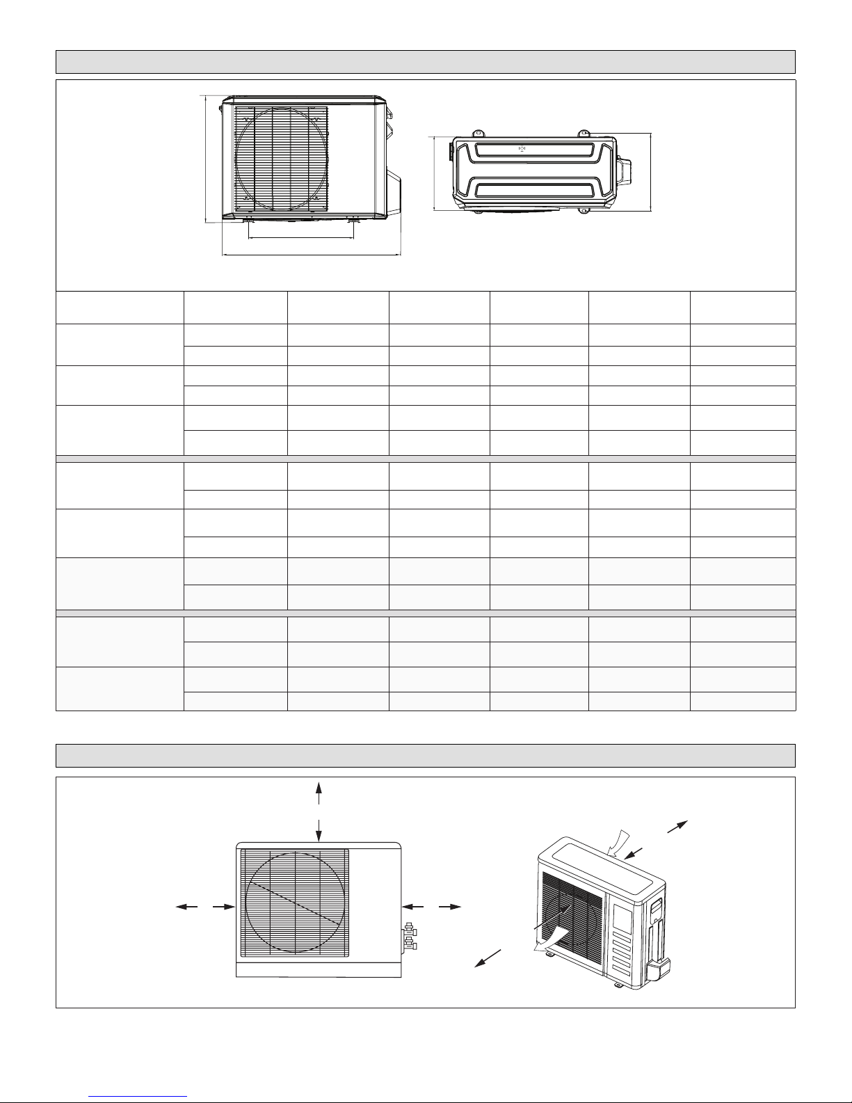
Outdoor Unit Dimensions
A
E
D
B
C
TYPICAL APPEARANCE OF UNITS
Model
MPA018S4M-*P
MPA030S4M-*P
MPA036S4M-*P
MPA048S4M-*P
MPB018S4M-*P
MPB030S4M-*P
MPB036S4M-*P
MPB048S4M-*P
MLA018S4M-*P
MLA030S4M-*P
MLA036S4M-*P
Unit of
Measurement
A B C D E
inches 35-3/4 22 27-3/8 12-3/4 13-1/8
mm 911 559 695 324 333
inches 37-1/4 25-1/4 31-7/8 15-1/2 16
mm 946 641 810 394 406
inches 36-7/8 32-7/8 54-1/2 15-3/8 16
mm 937 835 1385 391 408
inches 36 21-1/4 27-5/8 13-1/4 13-3/4
mm 914 540 702 335 350
inches 40-3/4 26-1/2 31-7/8 15-1/8 15-7/8
mm 1035 673 810 386 403
inches 41-3/4 25 52-1/2 16-3/8 15-7/8
mm 1060 634 1333 415 404
inches 40-5/8 26-1/2 31-7/8 16-5/8 15-7/8
mm 1032 673 810 422 403
inches 41-1/8 25 52-1/2 15-3/8 15-7/8
mm 1045 635 1334 391 403
Figure 2. Outdoor Unit Dimensions - Inches (mm)
Outdoor Unit Clearances
12
(305)
1
Minimum rear clearance can be 6 inches (152 mm) when mounted on brackets
and with no obstructions on the other three sides.
Figure 3. Outdoor Unit Clearances - Inches (mm)
24 (610)
24
(610)
4
79
(2007)
Air Outlet
Air Inlet
1
12
(305)
Page 5

Torque Requirements for Caps and
Fasteners
When servicing or repairing HVAC components, ensure
the fasteners are appropriately tightened. “Table 1. Torque
Requirements” provides torque values for fasteners.
IMPORTANT
Only use Allen wrenches of sufcient hardness (50Rc -
Rockwell scale minimum). Fully insert the wrench into
the valve stem recess.
Service valve stems are factory-torqued from 9 ft.-lbs.
(12 N*m) for small valves, to 25 ft.-lbs. (34 N*m) for large
valves) to prevent refrigerant loss during shipping and
handling. Using an Allen wrench rated at less than 50Rc
risks rounding or breaking off the wrench, or stripping
the valve stem recess.
See the Lennox Service and Application Notes C-08-1
for further details and information.
Table 1. Torque Requirements
Parts
Service valve cap 8 ft.-lb. 11
Sheet metal screws 16 in.-lb. 2
Machine screws #10 27 in.-lb. 3
Compressor bolts 7 ft.-lb. 10
Gauge port seal cap 8 ft.-lb. 11
Recommended Torque
U.S. Newton-Meter- N
Outdoor Unit Installation
Placement Considerations
CAUTION
In order to avoid injury, take proper precaution when
lifting heavy objects.
Consider the following when positioning the unit:
• In coastal areas or other places with salty atmosphere
of sulfate gas, corrosion may shorten the life of the
unit. In coastal areas, the coil should be cleaned with
potable water several times per year to avoid corrosive
buildup (salt)
• Some localities are adopting sound ordinances based
on the unit’s sound level registered from the adjacent
property, not from the property where the unit is installed. Install the unit as far as possible from the property line
• When possible, do not install the unit directly outside
a window. Glass has a very high level of sound transmission
• Install unit level
Building Structure
Ground
Level
Figure 4. Install Unit Level
• Choose a place solid enough to bear the weight and
vibration of the unit, where the operation noise will not
be amplied
• Choose a location where the hot air discharged from
the unit or the operation noise will not be a nuisance
to neighbors
• Avoid installing the outdoor unit near a bedroom or
other places where noise may cause a problem
• There must be sufcient space to carry the unit into
and out of the site
• There must be unobstructed air ow around the air inlet and the air outlet
• The unit must not be installed in areas where a ammable gas leak may occur
• Install the outdoor unit a minimum of 3 feet (1m) away
from any antenna, power cord (line), radio, telephone,
security system, or intercom. Electrical interference
and radio frequencies from any of these sources may
affect operation
• Since water drains from the outdoor unit during various stages of operation, do not place anything which
may be damaged by moisture under the unit
Direct Sunlight, Rain, Snow and Ice Protection
• If the outdoor unit is subjected to prolonged exposure
to direct sunlight with temperatures over 100°F (38°C)
a canopy is recommended as illustrated in “Figure 5.
Outdoor Unit on Pedestal (Stand) and Protective Can-
opy” on page 6 or “Figure 10. Dog House-Style
Shelter” on page 7
IMPORTANT
The construction of a canopy or shade is necessary
because of an ambient limit control set to 122°F (50°C)
to protect the electronics. If the outdoor unit is placed in
direct sunlight it is possible that the limit may activate
and shut down the unit.
• Place unit away from overhanging roof lines which
would allow water or ice to drop on, or in front of, coil or
into unit. Construct a canopy as illustrated in “Figure 5.
Outdoor Unit on Pedestal (Stand) and Protective Can-
opy” on page 6
5
Page 6

• The unit base should be elevated above the depth of
Protective canopy
Air Inlet
Air Outlet
Air Outlet
Air Inlet
12 in
305 mm
79 in
2007 mm
average snows as illustrated in “Figure 6. Outdoor Unit
on Brackets above Snow Line” on page 6
• In heavy snow areas, do not place the unit where drifting will occur as illustrated in “Figure 7. Outdoor Unit
Air Flow Obstructed by Snow” on page 6
• Carefully consider how to manage defrost water disposal to prevent ice from blocking walkways or creating a safety hazard near the outdoor unit as illustrated
in “Figure 8. Avoid Defrost Water Ice Hazard” on page
6
Protective canopy
24 in
610 mm
12 in
305 mm
Air Inlet
Air Outlet
Figure 7. Outdoor Unit Air Flow Obstructed by
Snow
Pedestal
(stand)
Side View
Front View
Pedestal
(stand)
Figure 5. Outdoor Unit on Pedestal (Stand) and
Protective Canopy
Figure 6. Outdoor Unit on Brackets above Snow
Line
Figure 8. Avoid Defrost Water Ice Hazard
Prevailing Winds
Normally wind bafes are not required for a outdoor unit.
However, in order to maximize reliability and performance,
the following best practices should be followed.
If unit coil cannot be installed away from prevailing winter
winds, some method of protecting the coil is recommended.
However, minimum clearances as reference in “Figure 3.
Outdoor Unit Clearances - Inches (mm)” on page 4
must be observed at all times.
Common application examples are:
• When prevailing winds are from the air inlet side, then
position the wind barrier a minimum of 12 inches (305
mm) from the unit as illustrated in “Figure 9. Wind Barrier”
• When prevailing wind is into the discharge side, then
position the wind barrier a minimum 79 inches (2007
mm) from the front of the unit as illustrated in “Figure
9. Wind Barrier”
• Outdoor unit can be installed in a dog house style shel-
ter as illustrated in”Figure 10. Dog House-Style Shelter”
• Outdoor unit can be installed in a alcove or under a
roof overhang as illustrated in “Figure 11. Unit installed
in Alcove”
6
Page 7

Prevailing Winter Winds from Air Inlet Side
Wind Barrier
Inlet Air
Discharge Air
Wind Barrier
Prevailing Winter Winds From Air Discharge Side
12” (305mm)
Min. Distance
79” (2007mm)
Min. Distance
Figure 9. Wind Barrier
Buried Refrigerant Pipe Protection
• All refrigerant lines must be insulated regardless of if
it is buried
• In addition to insulating each line of piping, buried lines
must rest inside a sealed, watertight conduit
• The conduit must be designed so it cannot collect and
retain water
Outdoor Unit Condensate Piping
Condensate formed during the heating and defrost
processes must be drained from heat pump units. Drain
holes are provided in the base of the units to ensure proper
drainage. Heat pumps must be raised when installed on a
concrete pad or the ground to allow drainage to occur. If
the heat pump unit is installed on wall mounting bracket,
insert the provided drain connector into one of the 1
inch (25 mm) drain holes and attached a eld-provided
insulated drain hose to the connector. Use eld-provided
rubber plugs to cover any unused drain holes.
24 in
12 in
305 mm
610 mm
NOTE - Minimum clearances shown.
24 in
610 mm
Figure 10. Dog House-Style Shelter
24 in
610 mm
12 in
305 mm
NOTE - Minimum clearances shown.
12 in
305 mm
610 mm
24 in
12 in
305 mm
Drain
Connector
Chassis
Condensate Drain
(location varies per model)
Figure 12. Condensate Drain
Securing the Outdoor Unit
Slab or Roof Mounting
Install the unit a minimum of 4 inches (102 mm) above the
roof or ground surface to avoid ice build-up around the
unit. Place the unit above a load bearing wall or area of
the roof that can adequately support the unit. Consult local
codes for rooftop applications.
CAUTION
Roof Damage!
This system contains both refrigerant and oil. Some
rubber roong material may absorb oil. This will cause
the rubber to swell when it comes into contact with oil.
The rubber will then bubble and could cause leaks.
Protect the roof surface to avoid exposure to refrigerant
and oil during service and installation. Failure to follow
this notice could result in damage to roof surface.
Figure 11. Unit installed in Alcove
7
Page 8

Securing Outdoor Unit to Slab, Frame, or Rails
If the outdoor unit is installed on a eld-provided slab or
frame, use lag bolts or equivalent to secure the outdoor
unit to the slab or frame.
Four Field-provided Anchor Bolts
Figure 13. Securing Outdoor Unit to Slab
Four Field-Provided
Anchor Bolts
Figure 14. Securing Outdoor Unit to Rails
Securing Outdoor Unit To Hanging Brackets
If the outdoor unit is installed on eld-provided wall
mounting brackets, use lag bolts or equivalent to secure
the outdoor unit to the bracket. Minimum rear clearance
can be reduced to 6 inches (152 mm) when mounted
on brackets and with no obstructions on the other three
sides. Allow for condensate disposal when placing units
above one another.
6 in
152 mm
Air Inlet
Air Outlet
Figure 15. Securing Outdoor Unit to Brackets
Both lines must be individually insulated.
1. The seal on the unit refrigerant piping connections
should remain in place until the last possible moment.
This will prevent dust or water from getting into the
refrigerant piping before it is connected.
2. CAREFULLY adjust refrigerant piping connections to
suit the application.
3. Slowly loosen one of the are nuts to release the
factory nitrogen charge from the indoor units only.
4. Remove the are nuts from the connections on the
unit and discard the seal from each of the piping
connections.
5. Slide the are nuts onto the ends of the eld-provided
refrigerant piping before using a suitable aring tool to
are the end of the copper pipe.
6. Apply recommended HFC-410A refrigerant lubricant
to the outside of the ared refrigerant lines.
IMPORTANT
The compressor in this unit contains PVE
oil (Polyvinylether). PVE oil is formulated for
hydrouorocarbon (HFC) refrigerants, such as HFC-
410A, which this system contains. While it may have
some miscibility properties with mineral-based oil and
POE oil (Polyolester), it is not recommended to mix PVE
oil with any other type of refrigerant oil.
7. Align the threaded connections with the
ared refrigerant lines. Tighten the are nuts
lightly at rst to obtain a smooth match as
illustrated in “Figure 16. Making Connections
(Male to Female Connection)” on page 9.
8. Once snug, continue another half-turn on each nut
which should create a leak-free joint. A torque wrench
may be used to tighten are nuts using “Table 3.
Flare Nut Torque Recommendations” on page 9
recommendations. Do not over-tighten a ared joint.
Flared connections should always be accessible
and must be insulated to prevent condensation.
9. After refrigerant piping has been installed and checked
for leaks, apply insulation over all ared connections.
Table 2. Refrigerant Piping and Indoor Unit
Connection Sizes
Size
(Btuh)
9000 1/4 3/8
12000 1/4 1/2
18000 1/4 1/2
24000 3/8
Liquid Line
in.
Gas Line
in.
5/8
Refrigerant Piping Connections
Field piping consists of two copper lines connecting
the outdoor unit to the indoor unit. “Table 1. Torque
Requirements” lists the connection sizes. The connections
are made using the provided brass are nuts at the end of
the refrigerant piping connections.
8
Page 9

A
B
CANT ON THE OUTSIDE OF
THE FLARE
Figure 16. Making Connections
(Male to Female Connection)
MALE FLARE
CONNECTION
• The largest cpacity indoor unit must be connected to
the lowest rerigerant connection ports on the outdoor
unit.
• The 24,000 Btu indoor unit is only allowed to be
connected to MPA048S4M, MPB048S4M and
MLA036S4M outdoor units.
NOTE: Each indoor unit must be piped AND wired to
the correct zone piping connections and wiring
terminals. Make sure that indoor unit A is wired
to the zone A terminal block and connected to the
appropriate refrigerant pipe connections.
outdoor
wire
C
A
B
D
indoor
IMPORTANT
Always use two wrenches when tightening are nuts to
avoid twisting refrigerant piping. DO NOT over-tighten
are nuts.
TORQUE WRENCH
TO INDOOR
UNIT
TO OUTDOOR UNIT
Figure 17. Tighten Flare Nut
Table 3. Flare Nut Torque Recommendations
Outside
Diameter
Inches
1/4 15 ft.-lb. (20 N) 1/4 turn
3/8 26 ft.-lb. (35 N) 1/2 turn
1/2 41 ft.-lb. (56 N) 7/8 turn
5/8 48 ft.-lb. (65 N) 1 full turn
Recommended
Torque
No torque wrench available
Finger tighten and use an
appropriately sized wrench to
turn an additional:
BACKUP
WRENCH
pipe
Unit D
Unit C
Unit B
Unit A
L4(ft)
L3(ft)
L2(ft)
L1(ft)
Unit D
Unit C
Unit B
Unit A
Figure 18. Pipe and Wire Each Zone Separately
C(1/4in)
C(3/8in)
B(1/4in)
B(3/8in)
A(1/4in)
A(1/2in)
Indoor Unit Installation
CAUTION
In order to avoid injury, take proper precaution when
lifting heavy objects.
Please refer to the installation instruction included with the
indoor unit for setup.
IMPORTANT
Pipe and wire to each zone separately.
Test each indoor unit separately to ensure proper
operation.
Connecting Multiple Capacity Indoor Units
Figure 19. Connecting Multiple Capacity Indoor
Units
9
Page 10

INDOOR UNIT
INDOOR UNIT
NOTE - Minimum Line Set
Length - 10 ft. (3 m) per
Indoor Unit
INDOOR UNIT
Maximum
Elevation -
Outdoor Unit
BELOW
Indoor Units
49 ft.
(15 m)
NOTE - Maximum Line Set
Length Includes ALL
piping in measurement
NOTE - Maximum Difference
in Elevation Between
Indoor Units - 33 ft. (10 m).
Maximum Line Set
Furthest Indoor Unit
OUTDOOR UNIT
33 ft. (10 m) for MPA
INDOOR UNIT
ABOVE Indoor Unit
INDOOR UNIT
Outdoor Unit Model No.
Maximum Number of
Indoor Units
Indoor Unit Connections Liquid / Gas
MPA018S4M-*P
MPB018S4M-*P
MLA018S4M-*P
Two Three Four Five
(2) 1/4 / 3/8 (3) 1/4 / 3/8
MPA030S4M-*P
MPB030S4M-*P
MLA030S4M-*P
Total Length of All Piping 98 ft. (30 m) 148 ft. (45 m) 197 ft. (60 m) 246 (75 m)
Maximum Line Set
Length - Furthest Indoor
66 ft. (20 m) 82 ft. (25 m) 98 ft. (30 m) 98 ft. (30 m)
Unit
49 ft. (15 m) for MLA and MPB
Maximum
Elevation -
Outdoor Unit
MPA036S4M-*P
MPB036S4M-*P
MLA036S4M-*P
(3) 1/4 / 3/8
(1)1/4 / 1/2
MPA048S4M-*P
MPB048S4M-*P
(3) 1/4 / 3/8
(2) 1/4 / 1/2
Figure 20. Multi-Zone Systems with All Indoor Unit Models
10
Page 11

Indoor / Outdoor Unit Match-Ups
Each system is formed of one outdoor unit and a selection
of indoor units as referenced in the Product Specications
(EHB). Only these combinations are allowed.
NOTE: Each indoor unit must be piped AND wired to
the correct zone piping connections and wiring
terminals. Make sure that indoor unit A is wired
to the zone A terminal block and connected to the
appropriate refrigerant pipe connections.
Table 4. Match-Ups
Outdoor
Model
MPA018S4M
MPB018S4M
Indoor Unit A
1/4” liq + 3/8” gas
Indoor Unit B
1/4” liq + 3/8” gas
MPA030S4M
MPB030S4M
Indoor Unit A
1/4” liq + 3/8” gas
Indoor Unit B
1/4” liq + 3/8” gas
Indoor Unit C
1/4” liq + 3/8” gas
No. of
Zones
Indoor Unit
Capacity
(Unit No.)
1 012 (A)1 1/4 in. x 1/2 in.
2
2
2
009 (A) 1/4 in. x 3/8 in.
009 (B) 1/4 in. x 3/8 in.
009 (B) 1/4 in. x 3/8 in.
012 (A)1 1/4 in. x 1/2 in.
012 (A)1 1/4 in. x 1/2 in.
012 (B)1 1/4 in. x 1/2 in.
1 018 (A)1 1/4 in. x 1/2 in.
2
2
2
2
2
2
009 (A) 1/4 in. x 3/8 in.
009 (B) 1/4 in. x 3/8 in.
009 (B) 1/4 in. x 3/8 in.
012 (A)1 1/4 in. x 1/2 in.
009 (B) 1/4 in. x 3/8 in.
018 (A)1 1/4 in. x 1/2 in.
012 (A)1 1/4 in. x 1/2 in.
012 (B)1 1/4 in. x 1/2 in.
012 (B)1 1/4 in. x 1/2 in.
018 (A)1 1/4 in. x 1/2 in.
018 (A)1 1/4 in. x 1/2 in.
018 (B)1 1/4 in. x 1/2 in.
009 (A) 1/4 in. x 3/8 in.
3
009 (B) 1/4 in. x 3/8 in.
009 (C) 1/4 in. x 3/8 in.
009 (B) 1/4 in. x 3/8 in.
3
009 (C) 1/4 in. x 3/8 in.
012 (A)1 1/4 in. x 1/2 in.
Line Set
Required
(Liquid x Gas)
Outdoor
Model
MPA030S4M
MPB030S4M
Indoor Unit A
1/4” liq + 3/8” gas
Indoor Unit B
1/4” liq + 3/8” gas
Indoor Unit C
1/4” liq + 3/8” gas
MPA036S4M
MPB036S4M
Indoor Unit A
1/4” liq + 1/2” gas
Indoor Unit B
1/4” liq + 3/8” gas
Indoor Unit C
1/4” liq + 3/8” gas
Indoor Unit D
1/4” liq + 3/8” gas
Table 4. Match-Ups
No. of
Zones
2
2
Indoor Unit
Capacity
(Unit No.)
009 (C) 1/4 in. x 3/8 in.
3
012 (A)
012 (B)
009 (B) 1/4 in. x 3/8 in.
3
009 (C) 1/4 in. x 3/8 in.
018 (A)
012 (A)
3
012 (B)
012 (C)1 1/4 in. x 1/2 in.
2
4
009 (B) 1/4 in. x 3/8 in.
018 (A) 1/4 in. x 1/2 in.
009 (B) 1/4 in. x 3/8 in.
024 (A)
2
4
012 (A) 1/4 in. x 1/2 in.
012 (B)
012 (B)
024 (A)
2
012 (B)
018 (A) 1/4 in. x 1/2 in.
2 018 (A) 1/4 in. x 1/2 in.
018 (B)
009 (B) 1/4 in. x 3/8 in.
3
009 (C) 1/4 in. x 3/8 in.
009 (D) 1/4 in. x 3/8 in.
009 (B) 1/4 in. x 3/8 in.
3
009 (C) 1/4 in. x 3/8 in.
012 (A) 1/4 in. x 1/2 in.
009 (B) 1/4 in. x 3/8 in.
3
009 (C) 1/4 in. x 3/8 in.
018 (A) 1/4 in. x 1/2 in.
009 (C) 1/4 in. x 3/8 in.
3
012 (A) 1/4 in. x 1/2 in.
012 (B)
Line Set
Required
(Liquid x Gas)
1
1/4 in. x 1/2 in.
1
1/4 in. x 1/2 in.
1
1/4 in. x 1/2 in.
1
1/4 in. x 1/2 in.
1
1/4 in. x 1/2 in.
2,3
3/8 in. x 5/8 in.
1
1/4 in. x 1/2 in.
1
1/4 in. x 1/2 in.
2,3
3/8 in. x 5/8 in.
1
1/4 in. x 1/2 in.
1
1/4 in. x 1/2 in.
1
1/4 in. x 1/2 in.
11
Page 12

Outdoor
Model
MPA036S4M
MPB036S4M
Indoor Unit A
1/4” liq + 1/2” gas
Indoor Unit B
1/4” liq + 3/8” gas
Indoor Unit C
1/4” liq + 3/8” gas
Indoor Unit D
1/4” liq + 3/8” gas
Table 4. Match-Ups
3
3
3
3
3
4
4
4
4
4
4
4
Indoor Unit
Capacity
(Unit No.)
009 (C) 1/4 in. x 3/8 in.
012 (B)1 1/4 in. x 1/2 in.
018 (A) 1/4 in. x 1/2 in.
009 (C) 1/4 in. x 3/8 in.
018 (A) 1/4 in. x 1/2 in.
018 (B)1 1/4 in. x 1/2 in.
012 (A) 1/4 in. x 1/2 in.
012 (B)1 1/4 in. x 1/2 in.
012 (C)1 1/4 in. x 1/2 in.
012 (C)1 1/4 in. x 1/2 in.
012 (B)1 1/4 in. x 1/2 in.
018 (A) 1/4 in. x 1/2 in.
012 (C)1 1/4 in. x 1/2 in.
018 (A) 1/4 in. x 1/2 in.
018 (B)1 1/4 in. x 1/2 in.
012 (B)1 1/4 in. x 1/2 in.
012 (C)1 1/4 in. x 1/2 in.
024 (A)
009 (B) 1/4 in. x 3/8 in.
009 (C) 1/4 in. x 3/8 in.
009 (D) 1/4 in. x 3/8 in.
009 (A)1 1/4 in. x 3/8 in.
009 (B) 1/4 in. x 3/8 in.
009 (C) 1/4 in. x 3/8 in.
009 (D) 1/4 in. x 3/8 in.
012 (A) 1/4 in. x 1/2 in.
009 (B) 1/4 in. x 3/8 in.
009 (C) 1/4 in. x 3/8 in.
009 (D) 1/4 in. x 3/8 in.
018 (A) 1/4 in. x 1/2 in.
009 (C) 1/4 in. x 3/8 in.
009 (D) 1/4 in. x 3/8 in.
012 (A) 1/4 in. x 1/2 in.
012 (B)1 1/4 in. x 1/2 in.
009 (C) 1/4 in. x 3/8 in.
009 (D) 1/4 in. x 3/8 in.
012 (B)1 1/4 in. x 1/2 in.
018 (A) 1/4 in. x 1/2 in.
009 (D) 1/4 in. x 3/8 in.
012 (A) 1/4 in. x 1/2 in.
012 (B)1 1/4 in. x 1/2 in.
012 (C)1 1/4 in. x 1/2 in.
No. of
Zones
3
Line Set
Required
(Liquid x Gas)
2,3
3/8 in. x 5/8 in.
Outdoor
Model
MPA048S4M
MPB048S4M
Indoor Unit A
1/4” liq + 1/2” gas
Indoor Unit B
1/4” liq + 1/2” gas
Indoor Unit C
1/4” liq + 3/8” gas
Indoor Unit D
1/4” liq + 3/8” gas
Indoor Unit E
1/4” liq + 3/8” gas
Table 4. Match-Ups
4
2
2
2
2
2
2
3
3
3
3
3
3
Indoor Unit
Capacity
(Unit No.)
012 (A) 1/4 in. x 1/2 in.
012 (B)
012 (C)1 1/4 in. x 1/2 in.
012 (D)1 1/4 in. x 1/2 in.
009 (B)
024 (A)
012 (B) 1/4 in. x 1/2 in.
018 (A) 1/4 in. x 1/2 in.
012 (B) 1/4 in. x 1/2 in.
024 (A)
018 (A) 1/4 in. x 1/2 in.
018 (B) 1/4 in. x 1/2 in.
018 (B) 1/4 in. x 1/2 in.
024 (A)
024 (A)
024 (B)
009 (A)
009 (B)
009 (C) 1/4 in. x 3/8 in.
009 (B)
009 (C) 1/4 in. x 3/8 in.
012 (A) 1/4 in. x 1/2 in.
009 (B)
009 (C) 1/4 in. x 3/8 in.
018 (A) 1/4 in. x 1/2 in.
009 (B)
009 (C) 1/4 in. x 3/8 in.
024 (A)
009 (C) 1/4 in. x 3/8 in.
012 (A) 1/4 in. x 1/2 in.
012 (B) 1/4 in. x 1/2 in.
009 (C) 1/4 in. x 3/8 in.
012 (B) 1/4 in. x 1/2 in.
018 (A) 1/4 in. x 1/2 in.
No. of
Zones
Line Set
Required
(Liquid x Gas)
1
1/4 in. x 1/2 in.
1
1/4 in. x 3/8 in.
2, 3
3/8 in. x 5/8 in.
2, 3
3/8 in. x 5/8 in.
2, 3
3/8 in. x 5/8 in.
2, 3
3/8 in. x 5/8 in.
2, 3
3/8 in. x 5/8 in.
1
1/4 in. x 3/8 in.
1
1/4 in. x 3/8 in.
1
1/4 in. x 3/8 in.
1
1/4 in. x 3/8 in.
1
1/4 in. x 3/8 in.
2, 3
3/8 in. x 5/8 in.
12
Page 13

Outdoor
Model
MPA048S4M
MPB048S4M
Indoor Unit A
1/4” liq + 1/2” gas
Indoor Unit B
1/4” liq + 1/2” gas
Indoor Unit C
1/4” liq + 3/8” gas
Indoor Unit D
1/4” liq + 3/8” gas
Indoor Unit E
1/4” liq + 3/8” gas
Table 4. Match-Ups
3
3
3
3
3
3
3
3
3
3
3
3
4
4
Indoor Unit
Capacity
(Unit No.)
009 (C) 1/4 in. x 3/8 in.
012 (B) 1/4 in. x 1/2 in.
024 (A)
009 (C) 1/4 in. x 3/8 in.
018 (A) 1/4 in. x 1/2 in.
018 (B) 1/4 in. x 1/2 in.
009 (C) 1/4 in. x 3/8 in.
018 (B) 1/4 in. x 1/2 in.
024 (A)
009 (C) 1/4 in. x 3/8 in.
024 (A)
024 (B)
012 (A) 1/4 in. x 1/2 in.
012 (B) 1/4 in. x 1/2 in.
012 (C)1 1/4 in. x 1/2 in.
012 (B) 1/4 in. x 1/2 in.
012 (C)1 1/4 in. x 1/2 in.
018 (A) 1/4 in. x 1/2 in.
012 (C) 1/4 in. x 1/2 in.
018 (A) 1/4 in. x 1/2 in.
018 (B)1 1/4 in. x 1/2 in.
012 (B) 1/4 in. x 1/2 in.
012 (C)1 1/4 in. x 1/2 in.
024 (A)
012 (B) 1/4 in. x 1/2 in.
018 (C)1 1/4 in. x 1/2 in.
024 (A)
012 (C)1 1/4 in. x 1/2 in.
024 (A)
024 (B)
018 (A) 1/4 in. x 1/2 in.
018 (B) 1/4 in. x 1/2 in.
018 (C)1 1/4 in. x 1/2 in.
018 (B) 1/4 in. x 1/2 in.
018 (C)
024 (A)
009 (A)1 1/4 in. x 3/8 in.
009 (B)1 1/4 in. x 3/8 in.
009 (C) 1/4 in. x 3/8 in.
009 (D) 1/4 in. x 3/8 in.
009 (B)1 1/4 in. x 3/8 in.
009 (C) 1/4 in. x 3/8 in.
009 (D) 1/4 in. x 3/8 in.
012 (A) 1/4 in. x 1/2 in.
No. of
Zones
Line Set
Required
(Liquid x Gas)
2, 3
3/8 in. x 5/8 in.
2, 3
3/8 in. x 5/8 in.
2, 3
3/8 in. x 5/8 in.
2, 3
3/8 in. x 5/8 in.
2, 3
3/8 in. x 5/8 in.
2, 3
3/8 in. x 5/8 in.
2, 3
3/8 in. x 5/8 in.
2, 3
3/8 in. x 5/8 in.
1
1/4 in. x 1/2 in.
2, 3
3/8 in. x 5/8 in.
Outdoor
Model
MPA048S4M
MPB048S4M
Indoor Unit A
1/4” liq + 1/2” gas
Indoor Unit B
1/4” liq + 1/2” gas
Indoor Unit C
1/4” liq + 3/8” gas
Indoor Unit D
1/4” liq + 3/8” gas
Indoor Unit E
1/4” liq + 3/8” gas
Table 4. Match-Ups
4
4
4
4
4
4
4
Indoor Unit
Capacity
(Unit No.)
009 (B)
009 (C) 1/4 in. x 3/8 in.
009 (D) 1/4 in. x 3/8 in.
018 (A) 1/4 in. x 1/2 in.
009 (B)
009 (C) 1/4 in. x 3/8 in.
009 (D) 1/4 in. x 3/8 in.
024 (A)
009 (C) 1/4 in. x 3/8 in.
009 (D) 1/4 in. x 3/8 in.
012 (A) 1/4 in. x 1/2 in.
012 (B) 1/4 in. x 1/2 in.
009 (C) 1/4 in. x 3/8 in.
009 (D) 1/4 in. x 3/8 in.
012 (B) 1/4 in. x 1/2 in.
018 (A) 1/4 in. x 1/2 in.
009 (C) 1/4 in. x 3/8 in.
009 (D) 1/4 in. x 3/8 in.
018 (A) 1/4 in. x 1/2 in.
018 (B) 1/4 in. x 1/2 in.
009 (C) 1/4 in. x 3/8 in.
009 (D) 1/4 in. x 3/8 in.
018 (B) 1/4 in. x 1/2 in.
024 (A)
009 (D) 1/4 in. x 3/8 in.
012 (A)
012 (B)
012 (C) 1/4 in. x 1/2 in.
No. of
Zones
Line Set
Required
(Liquid x Gas)
1
1/4 in. x 3/8 in.
1
1/4 in. x 3/8 in.
2, 3
3/8 in. x 5/8 in.
2, 3
3/8 in. x 5/8 in.
1
1/4 in. x 1/2 in.
1
1/4 in. x 1/2 in.
13
Page 14

Outdoor
Model
MPA048S4M
MPB048S4M
Indoor Unit A
1/4” liq + 1/2” gas
Indoor Unit B
1/4” liq + 1/2” gas
Indoor Unit C
1/4” liq + 3/8” gas
Indoor Unit D
1/4” liq + 3/8” gas
Indoor Unit E
1/4” liq + 3/8” gas
Table 4. Match-Ups
4
4
4
4
5
5
5
5
5
5
Indoor Unit
Capacity
(Unit No.)
009 (D) 1/4 in. x 3/8 in.
012 (B) 1/4 in. x 1/2 in.
012 (C)1 1/4 in. x 1/2 in.
018 (A) 1/4 in. x 1/2 in.
009 (D) 1/4 in. x 3/8 in.
012 (C)1 1/4 in. x 1/2 in.
018 (A) 1/4 in. x 1/2 in.
018 (B) 1/4 in. x 1/2 in.
012 (A) 1/4 in. x 1/2 in.
012 (B) 1/4 in. x 1/2 in.
012 (C)1 1/4 in. x 1/2 in.
012 (D)1 1/4 in. x 1/2 in.
012 (B) 1/4 in. x 1/2 in.
012 (C)1 1/4 in. x 1/2 in.
012 (D)1 1/4 in. x 1/2 in.
018 (A) 1/4 in. x 1/2 in.
009 (A)1 1/4 in. x 3/8 in.
009 (B)1 1/4 in. x 3/8 in.
009 (C) 1/4 in. x 3/8 in.
009 (D) 1/4 in. x 3/8 in.
009 (E) 1/4 in. x 3/8 in.
009 (B)1 1/4 in. x 3/8 in.
009 (C) 1/4 in. x 3/8 in.
009 (D) 1/4 in. x 3/8 in.
009 (E) 1/4 in. x 3/8 in.
012 (A) 1/4 in. x 1/2 in.
009 (B)1 1/4 in. x 3/8 in.
009 (C) 1/4 in. x 3/8 in.
009 (D) 1/4 in. x 3/8 in.
009 (E) 1/4 in. x 3/8 in.
018 (A) 1/4 in. x 1/2 in.
009 (B)1 1/4 in. x 3/8 in.
009 (C) 1/4 in. x 3/8 in.
009 (D) 1/4 in. x 3/8 in.
009 (E) 1/4 in. x 3/8 in.
024 (A)
009 (C) 1/4 in. x 3/8 in.
009 (D) 1/4 in. x 3/8 in.
009 (E) 1/4 in. x 3/8 in.
012 (A) 1/4 in. x 1/2 in.
012 (B) 1/4 in. x 1/2 in.
009 (C) 1/4 in. x 3/8 in.
009 (D) 1/4 in. x 3/8 in.
009 (E) 1/4 in. x 3/8 in.
012 (B) 1/4 in. x 1/2 in.
018 (A) 1/4 in. x 1/2 in.
No. of
Zones
Line Set
Required
(Liquid x Gas)
2, 3
3/8 in. x 5/8 in.
Outdoor
Model
MPA048S4M
MPB048S4M
Indoor Unit A
1/4” liq + 1/2” gas
Indoor Unit B
1/4” liq + 1/2” gas
Indoor Unit C
1/4” liq + 3/8” gas
Indoor Unit D
1/4” liq + 3/8” gas
Indoor Unit E
1/4” liq + 3/8” gas
MLA018S4M
Indoor Unit A
1/4” liq + 3/8” gas
Indoor Unit B
1/4” liq + 3/8” gas
MLA030S4M
Indoor Unit A
1/4” liq + 1/2” gas
Indoor Unit B
1/4” liq + 3/8” gas
Indoor Unit C
1/4” liq + 3/8” gas
Table 4. Match-Ups
5
5
5
5
2
2
2
2
2
2
2
2
2
2
2
2
3
Indoor Unit
Capacity
(Unit No.)
009 (D) 1/4 in. x 3/8 in.
009 (E) 1/4 in. x 3/8 in.
012 (A) 1/4 in. x 1/2 in.
012 (B) 1/4 in. x 1/2 in.
012 (C)1 1/4 in. x 1/2 in.
009 (D) 1/4 in. x 3/8 in.
009 (E) 1/4 in. x 3/8 in.
012 (B) 1/4 in. x 1/2 in.
012 (C)1 1/4 in. x 1/2 in.
018 (A) 1/4 in. x 1/2 in.
009 (E) 1/4 in. x 3/8 in.
012 (A) 1/4 in. x 1/2 in.
012 (B) 1/4 in. x 1/2 in.
012 (C)1 1/4 in. x 1/2 in.
012 (D)1 1/4 in. x 1/2 in.
012 (A) 1/4 in. x 1/2 in.
012 (B) 1/4 in. x 1/2 in.
012 (C)1 1/4 in. x 1/2 in.
012 (D)1 1/4 in. x 1/2 in.
012 (E)
009 (A) 1/4 in. x 3/8 in.
009 (B) 1/4 in. x 3/8 in.
012 (A)
009 (B) 1/4 in. x 3/8 in.
009 (B) 1/4 in. x 3/8 in.
018 (A)
012 (A)
012 (B)
009 (A)
009 (B) 1/4 in. x 3/8 in.
012 (A) 1/4 in. x 1/2 in.
009 (B) 1/4 in. x 3/8 in.
009 (B) 1/4 in. x 3/8 in.
018 (A) 1/4 in. x 1/2 in.
009 (B) 1/4 in. x 3/8 in.
024 (A)
012 (A) 1/4 in. x 1/2 in.
012 (B)
012 (B)
018 (A) 1/4 in. x 1/2 in.
024 (A)
012 (B)
018 (A) 1/4 in. x 1/2 in.
018 (B)
009 (A)
009 (B) 1/4 in. x 3/8 in.
009 (C) 1/4 in. x 3/8 in.
No. of
Zones
Line Set
Required
(Liquid x Gas)
1
1/4 in. x 1/2 in.
1
1/4 in. x 1/2 in.
1
1/4 in. x 1/2 in.
1
1/4 in. x 1/2 in.
1
1/4 in. x 1/2 in.
1
1/4 in. x 3/8 in.
2, 3
3/8 in. x 5/8 in.
1
1/4 in. x 1/2 in.
1
1/4 in. x 1/2 in.
2, 3
3/8 in. x 5/8 in.
1
1/4 in. x 1/2 in.
1
1/4 in. x 1/2 in.
1
1/4 in. x 3/8 in.
14
Page 15

Outdoor
Model
MLA030S4M
Indoor Unit A
1/4” liq + 1/2” gas
Indoor Unit B
1/4” liq + 3/8” gas
Indoor Unit C
1/4” liq + 3/8” gas
MLA036S4M
Indoor Unit A
1/4” liq + 1/2” gas
Indoor Unit B
1/4” liq + 1/2” gas
Indoor Unit C
1/4” liq + 3/8” gas
Indoor Unit D
1/4” liq + 3/8” gas
Table 4. Match-Ups
3
3
3
3
3
2
2
2
2
2
2
2
2
3
3
Indoor Unit
Capacity
(Unit No.)
009 (B) 1/4 in. x 3/8 in.
009 (C) 1/4 in. x 3/8 in.
012 (A) 1/4 in. x 1/2 in.
009 (C) 1/4 in. x 3/8 in.
012 (A) 1/4 in. x 1/2 in.
012 (B)1 1/4 in. x 1/2 in.
009 (B) 1/4 in. x 3/8 in.
009 (C) 1/4 in. x 3/8 in.
018 (A) 1/4 in. x 1/2 in.
018 (A) 1/4 in. x 1/2 in.
012 (B)1 1/4 in. x 1/2 in.
009 (C) 1/4 in. x 3/8 in.
012 (A) 1/4 in. x 1/2 in.
012 (B)1 1/4 in. x 1/2 in.
012 (C)1 1/4 in. x 1/2 in.
009 (B)1 1/4 in. x 3/8 in.
018 (A) 1/4 in. x 1/2 in.
009 (B)1 1/4 in. x 3/8 in.
024 (A)
012 (A) 1/4 in. x 1/2 in.
012 (B) 1/4 in. x 1/2 in.
012 (B) 1/4 in. x 1/2 in.
018 (A) 1/4 in. x 1/2 in.
012 (B) 1/4 in. x 1/2 in.
024 (A)
018 (B) 1/4 in. x 1/2 in.
018 (A) 1/4 in. x 1/2 in.
018 (B) 1/4 in. x 1/2 in.
024 (A)
024 (B)
024 (A)
009 (A)1 1/4 in. x 3/8 in.
009 (B)1 1/4 in. x 3/8 in.
009 (C) 1/4 in. x 3/8 in.
009 (B)1 1/4 in. x 3/8 in.
009 (C) 1/4 in. x 3/8 in.
012 (A) 1/4 in. x 1/2 in.
No. of
Zones
Line Set
Required
(Liquid x Gas)
2, 3
3/8 in. x 5/8 in.
2, 3
3/8 in. x 5/8 in.
2, 3
3/8 in. x 5/8 in.
2, 3
3/8 in. x 5/8 in.
2, 3
3/8 in. x 5/8 in.
Outdoor
Model
MLA036S4M
Indoor Unit A
1/4” liq + 1/2” gas
Indoor Unit B
1/4” liq + 1/2” gas
Indoor Unit C
1/4” liq + 3/8” gas
Indoor Unit D
1/4” liq + 3/8” gas
Table 4. Match-Ups
3
3
3
3
3
3
3
3
3
3
4
4
Indoor Unit
Capacity
(Unit No.)
009 (B)
009 (C) 1/4 in. x 3/8 in.
018 (A) 1/4 in. x 1/2 in.
009 (C) 1/4 in. x 3/8 in.
009 (B) 1 1/4 in. x 1/2 in.
024 (A)
009 (C) 1/4 in. x 3/8 in.
012 (A) 1/4 in. x 1/2 in.
012 (B) 1/4 in. x 1/2 in.
009 (C) 1/4 in. x 3/8 in.
012 (B) 1/4 in. x 1/2 in.
018 (A) 1/4 in. x 1/2 in.
009 (C) 1/4 in. x 3/8 in.
024 (A)
012 (B) 1/4 in. x 1/2 in.
009 (C) 1/4 in. x 3/8 in.
018 (A) 1/4 in. x 1/2 in.
018 (B) 1/4 in. x 1/2 in.
012 (A) 1/4 in. x 1/2 in.
012 (B) 1/4 in. x 1/2 in.
012 (C)1 1/4 in. x 1/2 in.
012 (B) 1/4 in. x 1/2 in.
012 (C)1 1/4 in. x 1/2 in.
018 (A) 1/4 in. x 1/2 in.
012 (B) 1/4 in. x 1/2 in.
012 (C)1 1/4 in. x 1/2 in.
024 (A)
012 (C)1 1/4 in. x 1/2 in.
018 (A) 1/4 in. x 1/2 in.
018 (B) 1/4 in. x 1/2 in.
009 (B)
009 (C) 1/4 in. x 3/8 in.
009 (D) 1/4 in. x 3/8 in.
009 (A)
009 (B)
009 (C) 1/4 in. x 3/8 in.
009 (D) 1/4 in. x 3/8 in.
012 (A) 1/4 in. x 1/2 in.
No. of
Zones
Line Set
Required
(Liquid x Gas)
1
1/4 in. x 3/8 in.
2, 3
3/8 in. x 5/8 in.
2, 3
3/8 in. x 5/8 in.
2, 3
3/8 in. x 5/8 in.
1
1/4 in. x 3/8 in.
1
1/4 in. x 3/8 in.
1
1/4 in. x 3/8 in.
15
Page 16

Table 4. Match-Ups
4
4
4
4
4
Indoor Unit
Capacity
(Unit No.)
009 (B)1 1/4 in. x 3/8 in.
009 (C) 1/4 in. x 3/8 in.
009 (D) 1/4 in. x 3/8 in.
018 (A) 1/4 in. x 1/2 in.
009 (C) 1/4 in. x 3/8 in.
009 (D) 1/4 in. x 3/8 in.
012 (A) 1/4 in. x 1/2 in.
012 (B) 1/4 in. x 1/2 in.
009 (C) 1/4 in. x 3/8 in.
009 (D) 1/4 in. x 3/8 in.
012 (B) 1/4 in. x 1/2 in.
018 (A) 1/4 in. x 1/2 in.
009 (D) 1/4 in. x 3/8 in.
012 (A) 1/4 in. x 1/2 in.
012 (B) 1/4 in. x 1/2 in.
012 (C)1 1/4 in. x 1/2 in.
012 (A) 1/4 in. x 1/2 in.
012 (B) 1/4 in. x 1/2 in.
012 (C)1 1/4 in. x 1/2 in.
012 (D)1 1/4 in. x 1/2 in.
Outdoor
Model
MLA036S4M
Indoor Unit A
1/4” liq + 1/2” gas
Indoor Unit B
1/4” liq + 1/2” gas
Indoor Unit C
1/4” liq + 3/8” gas
Indoor Unit D
1/4” liq + 3/8” gas
1
3/8 x 1/2 in. gas pipe adaptor is required for line set connection to outdoor unit
(furnished with outdoor unit).
2
1/4 x 3/8 in. liquid pipe adaptor is required for line set connection to the 048
outdoor unit (furnished with outdoor unit).
3
1/2 x 5/8 in. gas pipe adaptor is required for line set connection to the 048
outdoor unit (furnished with outdoor unit).
4
Not a valid combination when using the MPA036S4M.
No. of
Zones
Line Set
Required
(Liquid x Gas)
Leak Test and Evacuation
Air and moisture remaining in the refrigerant system will
have undesirable effects as indicated below:
• Pressure in the system rises
• Operating current rises
• Cooling or heating efciency drops
• Moisture in the refrigerant circuit may freeze
• Water may lead to corrosion of parts in the refrigeration system
The line set between the indoor and outdoor units
must be leak tested and evacuated to remove any noncondensables and moisture from the system.
there is any movement check system for leaks.
5. After the system is found to be free of leaks:
• Close valve on nitrogen cylinder.
• Relieve the nitrogen pressure by: loosening the
charge hose connector at the nitrogen cylinder.
• When the system pressure is reduced to normal,
disconnect the hose from the cylinder.
IMPORTANT
Use only oxygen-free nitrogen (OFN).
Triple Evacuation Procedure
A Micron or Torr gauge must be used for this procedure.
1. Discharge the oxygen-free nitrogen and evacuate the
system to a reading of 8000 Microns (8 Torr) using all
service valves.
2. Break the vacuum by allowing nitrogen into the port
connections (liquid and gas line pipes) until a positive
pressure is achieved.
3. Evacuate the system to a reading of 5000 Microns (5
Torr).
4. Break the vacuum by allowing nitrogen into the port
connections (liquid and gas line pipes) until a positive
pressure is achieved
5. Evacuate the system to a minimum reading of 500
Microns (0.5 Torr).
6. For a moisture-free system, ensure the vacuum is held
without movement for a minimum of 4 hours.
7. If vacuum fails to hold, carry out steps 2 through 6 until
vacuum holds.
Table 5. Pressure Test Specications
1 3 bar 44 psig Minimum of 10 minutes
2 15 bar 220 psig Minimum of 10 minutes
3 32 bar 470 psig Minimum of 10 minutes
4 45 bar 650 psig 1 hour. Stress test to prove the
integrity of the complete installation.
5 32 bar 470 psig 24 hours. Lower system pressure
test, after conrmation No. 4 was
successfully completed.
Leak Test
Use the following procedure to test for system leaks:
1. Connect the manifold gauge set and dry nitrogen gas
cylinder to the liquid and gas service ports.
2. Open valve on nitrogen cylinder.
3. Pressurize the system per the pressure test
specications in “Table 5. Pressure Test Specications”.
4. Check that the system pressure remains stable. If
16
Page 17

Wiring Connections
IMPORTANT
Install unit so that unit disconnect is accessible.
Use specied wiring and cable to make electrical
connections. Clamp cables securely and make sure that
connections are tight to avoid strain on wiring. Insecure
wiring connections may result in equipment failure and
risk of re.
Wiring must be installed so that all cover plates can be
securely closed.
WARNING
Electric Shock Hazard. Can cause injury or death. Unit
must be rounded in accordance with national and local
codes.
Line voltage is present at all components when unit is
not in operation. Disconnect all remote electric power
supplies before opening access panel. Unit may have
multiple power sources.
CAUTION
All terminal connections must be made as illustrated
in the following diagrams. Improperly connected wiring
could damage unit or cause communication errors
between indoor and outdoor units.
In the U.S.A., wiring must conform with current local codes
and the current National Electric Code (NEC). In Canada,
wiring must conform with current local codes and the
current Canadian Electrical Code (CEC).
Outdoor Unit
• Refer to unit nameplate for minimum circuit ampacity
and maximum over-current protection size
• Make all electrical power wiring connections at the outdoor unit
• Be sure to reattach all electrical box covers after connections are complete
Indoor Units
Refer to the installation instruction included with the indoor
unit for further details.
17
Page 18

IMPORTANT
All diagrams (Figure 23 through Figure 33) are typical wiring diagrams. Refer to the wiring diagram on the unit for actual
wiring.
From Power
Supply
208/230V Outdoor Unit
Terminal Block
2(A)
1(A)
L2
3(A)
Outdoor Unit
Figure 21. Connection Diagram - Systems 30k and Below
1(B)
2(B)
3(B)
208/230V Indoor Unit B
Terminal Block
1 2 3
Indoor Unit B
208/230V Indoor Unit A
Terminal Block
1 2 3
Indoor Unit A
From Power
Supply
L2
To Indoor Unit A
208/230V Outdoor Unit
Terminal Block
1(A)
3(A)
2(A)
1(B)
3(B)
2(B)
To Indoor Unit B
Outdoor Unit
Figure 22. Connection Diagram - Systems 36k and Above
1(C)
2(C)
To Indoor Unit C
1(E)
3(E)
1(D)
3(C)
2(E)
3(D)
2(D)
208/230V Indoor Unit
Terminal Block
1 2 3
208/230V Indoor Unit
Terminal Block
1 2 3
Indoor Unit E
Indoor Unit D
18
Page 19

CN6
INDOOR COIL OUTLET
TEMP.SENSOR
OUTDOOR
T4
TEMP. SENSOR
OUTDOOR
T3
L-OUT
2
CN38
COIL TEMP. SENSOR
T5
COMPRESSOR
DISCHARGE TEMP.
CN11
CN12
RED
BLUE
CN39
BLACK
RED
L2
L1
BLUE
BROWN
2(A)
1(A)
BLACK
BLUE
BROWN
BLACK
1(B)
3(B)3(A)
2(B)
4 WAY
VALVE
PAN
HEATER
CRANKCASE
HEATER
B
A
Figure 23. MPA018S4M-*P Outdoor Unit Wiring Diagram
L-PRO
LOW PRESSURE SWITCH
2
H-PRO
HIGH PRESSURE SWITCH
INDOOR COIL OUTLET
TEMP.SENSOR
RED
YELLOW
4
C
CN11
CN12
RED
BLUE
B
A
ELECTRONIC
EXPANSION
VALVE
OUTDOOR
T4
TEMP. SENSOR
OUTDOOR
T3
COIL TEMP. SENSOR
T5
COMPRESSOR
DISCHARGE TEMP.
CN38
6
ELECTRONIC
6
EXPANSION
VALVE
6
Figure 24. MPA030S4M-*P Outdoor Unit Wiring Diagram
BLACK
RED
BLUE
BLACK
BROWN
3(A)
1(A)
L2
2(A)
BROWN
1(B)
BLACK
BLUE
2(B)
3(B) 3(C)
BLUE
BLACK
BROWN
1(C)
2(C)
PAN
HEATER
CRANKCASE
HEATER
4 WAY
VALVE
19
Page 20

BLACK
W
RED
COMP
V
BLUE
Y/G
U
DRIVER BOARD
YELLOW
L
CODE PART NAME
COMP
H-PRO
EEV
FM1
HEAT_Y
HEAT_D
COMPRESSOR
HIGH PRESSURE SWITCH
ELECTRIC EXPANSIVE
VALVE
OUTDOOR DC FAN
CRANKCASE HEATER
PAN HEATER
BLACK
RED
BLUE
BLUE
BLUE
YELLOW
CN54
CN51
CN53
CN52
CN7
W
V
U
L-PRO
CN5 5
RED
BLACK
L
T5
SV
T3
T4
7
4-WAY1
SV
BLUE
BLUE
HEAT_Y
HEAT_D
T3
T4
H-PRO
L-PRO
PART NAMECODE
PFC INDUCTOR
LOW PRESSURE SWITCH
COMPRESSOR
DISCHARGE TEMP.
4-WAY VALVE
CONDENSER
TEMPERATURE SENSOR
OUTDOOR AMBIENT
TEMPERATURE SENSOR
TP
FM1
CN12 CN11
6
CN20
CN3
ORANGE
CN4
CN10
ORANGE
ORANGE
ORANGE
CN8
CN9
7
CN7
CN33
CN22
CN40
CN44
MAIN BOARD
BLACK
CN5
RED
CN6
P-1
Y/G
CN1
CN2
RED
BLACK
A
CN21
B
CN17
C
CN18
D
CN2 9
CN30
CN2 7
CN2 8
M
6
M
6
M
EEV
6
M
indoor coil
outlet temp.
sensor
BLACK
BLUE
Y/G
W
V
RED
V
U
COMP
IPM & PFC BOARD
CN15
U
CN55
W
CN14
RED
BLUE
CN39
DCFAN2
Figure 25. MPA036S4M-*P Outdoor Unit Wiring Diagram
YELLOW
YELLOW
CN2
CN5
CN6
MAIN BOARD
D C
CN30
CN26
6
6
ELECTRONIC
EXPANSION
VALVE C
L
B
CN23
6
ELECTRONIC
EXPANSION
VALVE B
A
CN15
6
ELECTRONIC
EXPANSION
VALVE A
P-6
T2B-A B C D E
E D B A
INDOOR COIL
OUTLET TEMP.
SENSOR
CN13
C
P-4
P-5
CN13
CN16
CN21
CN29
CN37
BLACK
CN3
CN1
BLACK
E
3
D
3
C
3
B
3
A
3
9NC
YELLOW
01NC
RED
CN8
T5
CN9
Ferrite bead
CH3
D
BLACK
12
4
RED
CH2
CN8
CN6
CN3
Ferrite bead
7
CN7
5
CN11
5
BLACK
RED
3
5
BLACK
CH1
5
Ferrite bead
CT1
CN39
CN4
DCFAN1
BLUE
C N1 7
C N1 8
BLUE
C N2 4
C N2 5
C N1 9
C N2 0
E
CN33
6
ELECTRONIC
ELECTRONIC
EXPANSION
EXPANSION
VALVE E
VALVE D
HEA T_Y
HEA T_D
4-W AY
SV
WHITE
T4
T3
Y/G
BLACK
BLUE
BROWN
BLACK
BLUE
BROWN
BLACK
BLUE
BROWN
BLACK
BLUE
BROWN
BLACK
BLUE
BROWN
H-PRO
L-PRO
XT3
XT2
XT1
CODE
LPPUS REWOP Y
COMP
2L
1L
3(E)
2(E)
TO E
1(E)
3(D)
2(D)
TO D
1(D)
3(C)
2(C)
TO C
1(C)
3(B)
2(B)
TO B
1(B)
3(A)
2(A)
TO A
1(A)
CT1
D
DCFAN1,DCFAN2
HEAT_Y
HEAT_D
H-PRO
L
L-PRO
SV
T5
T3
T4
PART NAME
COMPRESSOR
AC CURRENT DETECTOR
DIODE MODULE
OUTDOOR DC FAN
CRANKCASE HEATER
PAN HEATER
HIGH PRESSURE SWITCH
PFC INDUCTOR
LOW PRESSURE SWITCH
4-WAY VALVE
DISCHARGE
TEMP. SENSOR
OUTDOOR COIL
TEMP. SENSOR
OUTDOOR TEMP. SENSOR
Figure 26. MPA048S4M-*P Outdoor Unit Wiring Diagram
20
Page 21

INDO OR COI L OUTL ET
TEMP. SENSOR
BR OW N
BL UE
HE AT 1
HE AT 2
RE AC TO R
BL UE
BL UE
OUTDOOR
TEMPERATURE SE NSOR
OUTDOOR COIL
TEMPERATURE SENSOR
REACT0R2 R05094A
WHITE
WHITE
6
3
3
6
1(A)
3(A)
L2
2(A)
L1
BLACK
BLUE
BROWN
BLACK
BLUE
BROWN
BLACK
RED
1(B)
2(B)
3(B)
COMPRE SSOR DI SCHARG E
TEMPER ATURE SENSOR
Figure 27. MPB018S4M-*P Outdoor Unit Wiring Diagram
HEAT1
SV
HEAT2
WHITE
WHITE
6
BLACK
BLUE
BROWN
BLACK
RED
L2
BROWN
BROWN
BLUE
BLUE
BLACK
BLACK
1(A)
3(A)
2(A)
1(B)
3(B)
2(B)
1(C)
2(C)
3(C)
3
3
6
6
CRANKCASE
HEATER
PAN
HEATER
Figure 28. MPB030S4M-*P Outdoor Unit Wiring Diagram
21
Page 22

CO MP
FM 1
MAIN B OA RD
RED
BL ACK
U
V
W
Y/G
Y/G
L
L-PRO
T3
T4
H-PRO
Y/G
TP
V
U
CN19
CN51
CN55
W
EXV
BLACK
DRIVER BOARD
RED
7
7
YELLOW
BLUE
P-1
CN53
CN3
CN4
CN10
CN40
CN22
CN44
C N8
C N9
CN7
C N2
C N1
CN5
CN54
CN52
CN33
CN6
SV
4-WAY
VALVE
BLUE
BLUE
HEAT_2
HEAT_1
BLACK
RED
BLUE
BLUE
BLUE
YELLOW
RED
BLACK
RED
BLACK
CN20
M
6
A
CN21
M
6
B
CN17
M
6
C
CN18
M
6
D
CN30
C N2 9
C N2 8
C N2
7
CODE PART NAME
COMPRESSOR
HEAT _2
4-WAY VALVE
COMP
EXV
ELECTRIC EXPANSIO N
VALVE
H-PRO
L-PRO
LOW PRE SSURE SWITCH
HIGH PRESSURE SWIT CH
T3
T4
OUTDOOR COIL
TEMPERATU RE SENSOR
OUTDOOR
TEMPERAT URE SENSOR
PAN HEAT ER
SV
L
PFC INDUCTOR
T2B
INDOOR COIL OUTLET
TEMPERAT URE SENSOR
TP
COMPRESSOR D ISCHARGE
TEMPERAT URE SENSOR
FM1
OUTDOOR DC FAN
PART NAMECODE
BLUE
BLUE
RDE
BLACK
BLACK
RDE
EXV
EXV
EXV
HEAT _1
CRANKCAS E HEAT ER
Figure 29. MPB036S4M-*P Outdoor Unit Wiring Diagram
DR IV ER B OA RD
CODE
PART NAME
COMPRESSOR
D
HEAT _1
CT1
AC CURRENT DETECTOR
4-WAY VALVE
COMP
EXV
ELECTRIC EXPANSIO N
VALVE
H-PRO
L-PRO
LOW PRESSURE SWITCH
HIGH PRESSURE SWITCH
T3
T4
OUTDOOR COIL
TEMPERATU RE SENSOR
OUTDOOR
TEMPERAT URE SENSOR
CRANKCAS E HEATER
DIODE MODULE
SV
L
PFC INDUCTOR
TP
COMPRESSOR DISCHA RGE
TEMP ERATURE SENS OR
MAIN BOARD
FM1, FM2
OUTDOOR DC FAN
L2
L1
XT 1
D
12
3
4
5
P5
CN37
FAN1
RED
CN4
CN2
CN3
CN1
CO MP
U
V
W
Y/G
CN6
CN9
10
3
CN1
CN2
L
YELLOW
YELLOW
U
V
W
BLUE
BLACK
RED
Y/G
XT 2
XT 3
PO WE R S U PP LY
CN29
CN21
CN16
CN13
RED
BLACK
BLACK
RED
BLACK
P9
CH1
CT1
FM 2
FM 1
Y/G
Y/G
DC MOT OR
DR IV ER B OA RD
CON1
FAN1
CN1
FAN2
3
3
P6
2
CN6
CN3
CN19
CN20
CN24
CN25
CN17
CN18
HEAT_2
HEAT_1
SV
4-WAY
VALVE
BLUE
BLUE
ORAN GE
ORA NGE
RED
BLACK
CH2
CH2
CH2
~
~
~
Y/G
Y/G
HEAT_2
PAN HEATER
T2B
INDOOR COIL
TEMPER ATUR E SENSOR
XT
TERMINAL STRIP
Figure 30. MPB048S4M-*P Outdoor Unit Wiring Diagram
22
Page 23

INDUCTOR
1R25027
D R IV E R B O A R D
INDOOR COIL OUTLET TEMP SENSOR
OUTDOOR TEMP SENSOR
OUTDOOR TEMP SENSOR
COMPRESSOR DISCHARGE
TEMP SENSOR
E X V
E X V
GN D
P-1
SV
HE A T _1
4 WAY
CR A N K C AS E
VALVE
HE A T ER
INDUCTOR 2R0509A
Figure 31. MLA018S4M-*P Outdoor Unit Wiring Diagram
HE A T _1
HE A T _2
HE A T _2
PAN
HE A T ER
TE M P. S EN S O R
IN D O O R C O IL O U T L ET
HEAT_1
CRANKCASE HEATER
HEAT_2
Figure 32. MLA030S4M-*P Outdoor Unit Wiring Diagram
COMPRESSOR DISCHARGE
TEMP. SENSOR
OUTDOOR COIL
TEMP. SENSOR
OUTDOOR
TEMP. SENSOR
INDOOR COIL OUTLET
TEMP. SENSOR
23
GN D
P-1
Page 24

HE A T _2
HE A T _1
IND O O R C OIL
OU T L ET
TE M P. S EN SO R
Figure 33. MLA036S4M-*P Outdoor Unit Wiring Diagram
HE A T _1
HE A T _2
AC CURRENT DETECTOR
PAN HEATER
COMPRESSOR DISCHARGE
TEMP. SENSOR
OUTDOOR COIL
TEMP. SENSOR
OUTDOOR
TEMP. SENSOR
INDOOR COIL OUTLET
TEMP. SENSOR
Unit Start-Up
IMPORTANT
Units should be energized 24 hours before unit
start-up to prevent compressor damage as a result
of slugging.
1. Inspect all factory-installed and eld-installed wiring
for loose connections.
2. Verify that the manifold gauge set is connected.
3. Add additional refrigerant charge if required before
opening valves and while system is still under a
vacuum.
4. Open the liquid and gas line master valves and each
individual port’s service valve to release the refrigerant
charge contained in outdoor unit into the system.
5. Replace the stem caps and tighten to the value listed
in “Table 1. Torque Requirements” on page 5.
6. Check voltage supply at the outdoor unit terminal strip.
The voltage must be within the range listed on the
unit’s nameplate. If not, do not start the equipment
until you have consulted with the power company and
the voltage condition has been corrected.
7. Refer to the included user guide to operate the system
using the provided remote control.
8. Visually check for binding of both indoor and outdoor
fans.
Refrigerant Charge
The outdoor unit is factory-charged with refrigerant.
Calculate the additional refrigerant required according to
the length of the liquid pipe (one way) between the outdoor
unit and indoor unit connections.
Be sure to add the proper amount of additional refrigerant.
Failure to do so may result in reduced performance.
Table 6. Refrigerant Charge
System
Two-port 50 ft. (15 m)
Threeport
Four-port 100 ft. (30 m)
Five-port 125 ft. (38 m)
Pre-charge
Pipe Length
75 ft. (23 m)
Amount of Refrigerant to add
0.16 oz ((L1 ft + L2 ft) - 50 ft)
0.005 kg ((L1 m + L2 m) - 15 m)
0.16 oz ((L1 ft + L2 ft + L3 ft) - 75 ft)
0.005 kg ((L1 m + L2 m + L3 m) - 23
m)
0.16 oz ((L1 ft + L2 ft + L3 ft + L4 ft)
- 100 ft)
0.005 kg ((L1 m + L2 m + L3 m + L4
m) - 30 m)
0.16 oz ((L1 ft + L2 ft + L3 ft + L4 ft +
L5 ft) - 125 ft)
0.005 kg ((L1 m + L2 m + L3 m + L4
m + L5 m) - 38 m)
24
 Loading...