

Page 1
© 2004 Lennox Industries Inc.
Dallas, Texas, USA
Litho U.S.A.
504,927M
5/2004
LZP-4
ZONE CONTROL PANEL
INSTALLATION INSTRUCTIONS FOR ZONE CONTROL PANELS
USED WITH LENNOX HEATING AND COOLING EQUIPMENT
Shipping & Packing List
Package 1 of 1 contains the following:
(1) Model LZP-4 Zone Control Panel
(1) Model 88K38 Temperature Sensor
(1) Installation Instructions
(1) Owners Manual
(1) Warranty Card
Required Components (ordered separately):
24 VAC Transformer – The size of the transformer
needed is determined by the total power
requirements for the control panel, thermostats and
dampers. The control panel and thermostat together
require 10VA. The dampers require 10VA each. The
size of the transformer will depend on the greatest
number of dampers that could be energized at any
given time. NOTE – When using power close, spring
open dampers, at least one zone’s dampers will not
be energized during a heating or cooling call.
Thermostats – see selection chart on page 5.
Only 24-volt electronic thermostats with a common
connection are to be used with this zoning panel. Do
not use mechanical or power robbing thermostats.
Dampers – 2 or 3-wire, 24-volt dampers required.
2-wire, power closed/spring open preferred.
Application
• Up to four zones
• Single or two-stage furnace
• Single or two-stage air conditioner
• Single or two stage-heat pump with one stage of
electric auxiliary heat; separate emergency heat
output available
• Single or two stage-heat pump with single-stage fossil
fuel auxiliary heat (dual fuel system)
Features
• Adjustable high and low discharge air temperature limits
• Vacation (central) mode setting
• Staging control by number of zones calling
• Staging control by time or thermostat input
• Auxiliary heat control by time or thermostat input
• Standard single-stage heat/cool thermostats or heat
pump thermostats can be used to control heat pumps
or multi-stage equipment
• Dual fuel system compatible
• ON/OFF duct air purge control
• Visible LED outputs
• Time Delay Override
• Zone1 or Any Zone mode control
• 2 or 3-wire damper compatibility
ZONING SYSTEM
TABLE 1 – TRANSFORMERS
Part Number Size Voltage Description
10P17 40VA 120/208/240V-24V
10P87 50VA 120/208/240V-24V
12P61 75VA 120/208/240V-24V
83P74 4" Square Electrical Box
Page 2
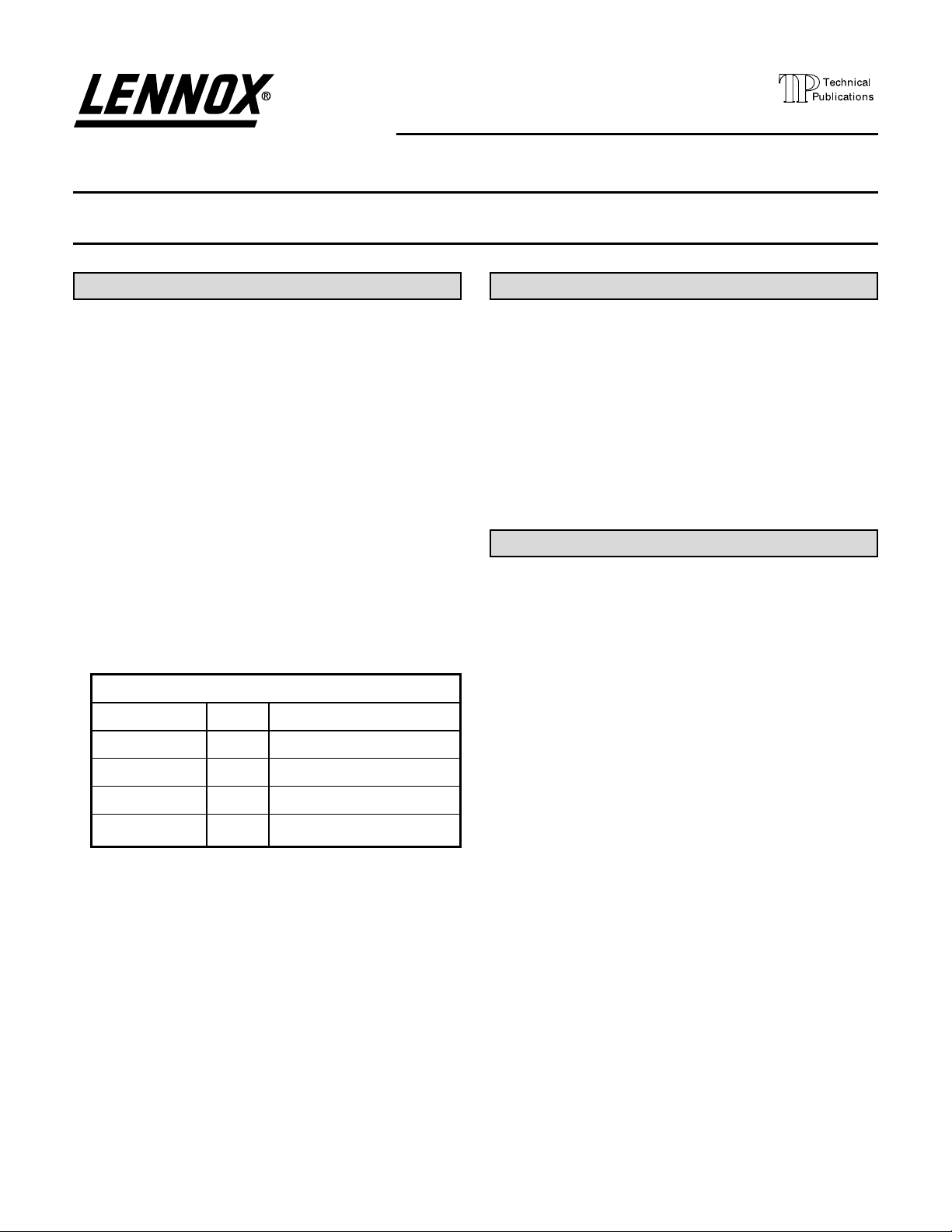
FIGURE 1 – LZP-4 CONTROL PANEL SCHEMATIC
Page 3
Installation
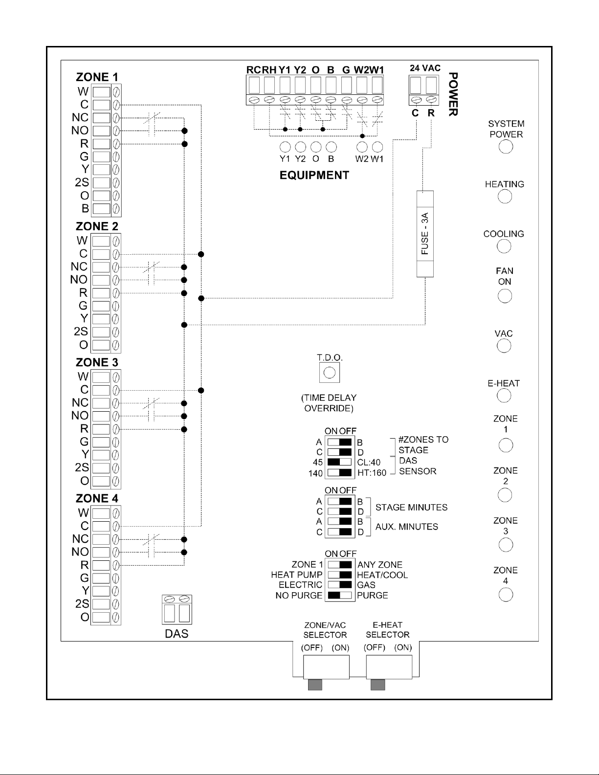
FIGURE 2 – ENCLOSURE BASE WITH
CIRCUIT BOARD
• Install the control panel indoors only. If the
Vacation and/or Emergency Heat switches on the
control panel will be used by the owner, mount in
a location that is readily accessible to the owner.
• Install the control panel in a non-condensing
environment.
• Do not install the control panel in a room where it
will be exposed to elevated humidity levels such
as a laundry room.
• Do not install the control panel directly to
foundation walls, HVAC equipment or ductwork,
where moisture may condense on the enclosure.
• Do not install the control panel in a location where
the temperature will exceed 140°F or will drop
below 32°F.
1. Press in the cover latch on the top of the enclosure
and pull open the cover (see Figure 2).
2. There are six (6) keyholes on the base of the
enclosure. Use the four that are visible with the circuit
board in place.
Cover
Latch
Remove
Screw
6 – Mounting keyholes
(2 located under circuit board)
Flex back board
retainer latches
b. Carefully remove the screws securing the circuit
board to the base.
c. Flex back the latches holding the circuit board
to release.
d. Re-install the circuit board after installing the base.
CAUTION
Electrostatic discharge can damage the control.
Touch a grounded metal object before touching
the circuit board, and then only touch the circuit
board on the edges when handling.
3. Use #8 screws (field supplied) to install the base.
a. If space limits the use of the outside keyholes, the
circuit board must be removed from the base to
use the two center keyholes.
The above illustration shows a system where three of the
four zones are used.
WARNING
Improper installation, adjustment, alteration,
service or maintenance can cause property
damage, personal injury or loss of life. Installation
and service must be performed by a qualified
installer, service agency or the gas supplier.
R
NC
NO
2S
Y
W
C
G
0
R
ZONE 4
J4
R111
R124
R94
D44
J1
D45
R96
R14
R13
DAS
R95
C3
R12
U7
ZONE/VAC
SELECTOR
C35
TP4
R28
R5
R4
SW6
R25
R29
HEAT PUMP
D16
NO PURGE
ELECTRIC
D13
D15
Zone 1
D11
R23
R30
R27
SW5
TP3
SELECTOR
E-HEAT
SW3
ANY ZONE
HEAT/COOL
GAS
PURGE
RV9
C22
R70
R71
+
R93
R72
D52
D59
R73
C26
C30
+
+
D36
C18
+
D58
D53
R123
R68
K7
R109
D37
R121
R78
R69
R110
R112
R126
U6
R31
61
C1
C36
1
R8
R10
R9
R7
10
C2
140
U2
45
A
C
A
C
A
C
SW1
D23
BDB
STAGE MINUTES
ZONE
4
TDO
SW4
CL:40
HT:160
D
B
R1
SENSOR
TO STAGE
DAS
#OFZONES
ZONE
3
D26
SW2
D
AUX. MINUTES
NC
C
R
W
NO
2S
YG0
RV12
R49
R105
R50
D64
R51
D47
R52
C32
C24
D27
+
C14
D67
+
D50
R99
R43
D29
R46
R41
R138
R134
R100
R106
44
R11
R20
R18
R19
27
R17
C5
C4
Y1
TP7
GND
TST
TP2
R15
VCC
24VDC
TP6
U1
ZONE
D24
D32
2
2S
ZONE 3
J5
R137
+
R133
C34
TP5
1
R139
R53
R89
R122
R82
R90
R81
R107
R91
R84
D48
D56
D65
C25
C28
+
D39
+
R92
+
D38
R83
C20
+
R74
D41
R85
U5
C12
D21
R32
U4
D19
C6
+
+
C10
ZONE
C19
C33
R57
R56
D51
D66
R101
D60
R135
R76
D43
R117
R102
D28
R58
C15
R136
R75
R140
R108
R118
R125
+
R47
D35
R59
R42
U3
K8
+
C7
Q1
D18
Q1
+
C8
C9
E-HEAT
R24
VAC
D12
D14
R26
B
NO
NC
C
RWYG0
ZONE 2
J6
R127
R60
RV11
RV14
R61
R62
D57
R63
C29
+
D30
C17
+
R86
RV10
+
D61
R119
R44
D33
K9
R120
R64
R77
R128
RV13
RV1
K6
K1
RV2
RV7
K2
RV3
D20
RV8
C11
Lennox LXZ-4 49M9201
R22
R16
COOLING
FAN
ON
D17
D5
R40
F2
F1
D8
R87
D40
C21
D42
K5
SPARE FUSE
MAIN FUSE
NCCNO
2S
R103
D46
C23
+
D49
R79
R80
R88
RV6
K10
HEATING
W
YG0
R131
+
D63
R97
R98
R104
ZONE 1
J7
R115
R35
R55
R39
R65
R36
R66
D54
D62
R37
R67
C27
C31
+
+
D31
D22
C13
C16
D55
+
+
R113
R33
R129
R48
D34
D25
R114
R130
R54
R34
R45
R38
R116
R132
RV16
RV15
J2
RHRC
D10
K3
Y1
D6
RV4
Y2
D1
0
D3
B0W1
K4
B
D2
RV5
D4
W2GY2Y1
W2
D9
W1
EQUIP.
C
J3
24VAC
RC
POWER
R
Rev. 0
R21
R2
SYSTEM
POWER
R3
D7
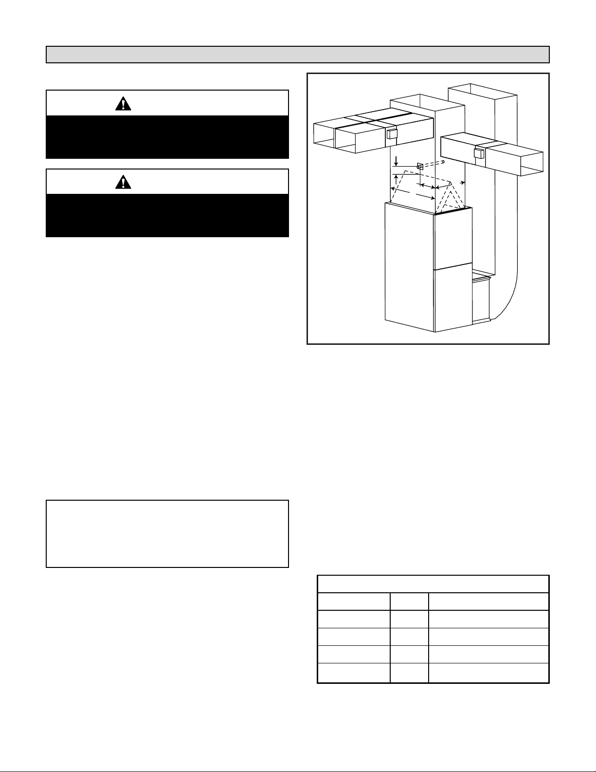
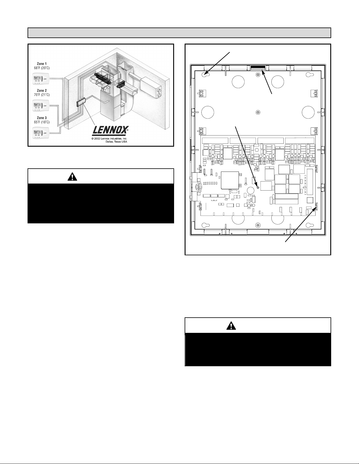
FIGURE 3 – DISCHARGE AIR SENSOR LOCATION
Page 4
4. Install and Wire the Discharge Air Temperature Sensor
The tip of the sensor must be located in a region of fully
mixed supply of air before the take-offs (not in a dead
air space) in order for the system to work correctly.
a. Wire discharge air temperature probe to control
center using thermostat wire. Note that the
temperature sensor is not polarity sensitive.
b. Be sure that the tip of the sensor is located at least
15 inches from the top of the indoor coil if using a
furnace, or at least 15 inches from the top of the
electric heat section if using a coil blower. Mount
the sensor in the discharge plenum, 1/3 of the
depth (D/3) of the plenum (D) from the front (the
front is the side with the furnace or CB access
doors), and centered side to side. Move the
adjustable bracket along the length of the
discharge air sensor to achieve proper sensor tip
location (tip of sensor to be located at W ÷ 2).
The sensor can be mounted from any side of the
plenum, as long as the tip of the sensor is in the
correct position. See Figure 3.
Installation (continued)
IMPORTANT: The discharge air sensor is required.
If a short or open circuit is detected between the
Discharge Air Sensor terminals, the control panel
will only respond to Zone 1 and the dampers will
stay in their normal position.
Sizing the Transformer:
The system requires approximately 10 VA for the
control panel and thermostats and 10 VA for each
damper. The size of the transformer will depend on the
greatest number of dampers that could be energized
at any given time (at least one zone’s dampers will not
be energized during a heating or cooling call when
using power close, spring open dampers). The size of
the transformer must not exceed 75VA. If the value is
greater than 75VA, some dampers will need to be
powered by a separate transformer – refer to Field
Wiring Damper Diagram 2 on page 10.
For instance, if you have 3 dampers, then you would
require 10VA for the system, 20VA (10VA X 2) for the
dampers for a total of 30VA, so catalog number 10P17
would be an adequate transformer size at 40VA.
The transformers listed in this chart include a plate
mount for a 4" square electrical box.
TABLE 1 – TRANSFORMERS
Part Number Size Voltage Description
10P17 40VA 120/208/240V-24V
10P87 50VA 120/208/240V-24V
12P61 75VA 120/208/240V-24V
83P74 4" Square Electrical Box
CAUTION
As with any mechanical equipment, personal injury
can result from contact with sharp sheet metal
edges. Be careful when you handle this equipment.
CAUTION
Before attempting to perform any service or
maintenance, turn the electrical power to unit OFF
at disconnect switch.
5. Install the system transformer – DO NOT USE the
HVAC equipment transformer to power the control
panel. Refer to the instructions provided with the
transformer.
18 AWG thermostat wire minimum recommended.
15"
D/3
D
W
FRONT
Page 5
Installation (continued)
6. Install the thermostats. Refer to the instructions
provided with the thermostat.
18 AWG thermostat wire minimum recommended.
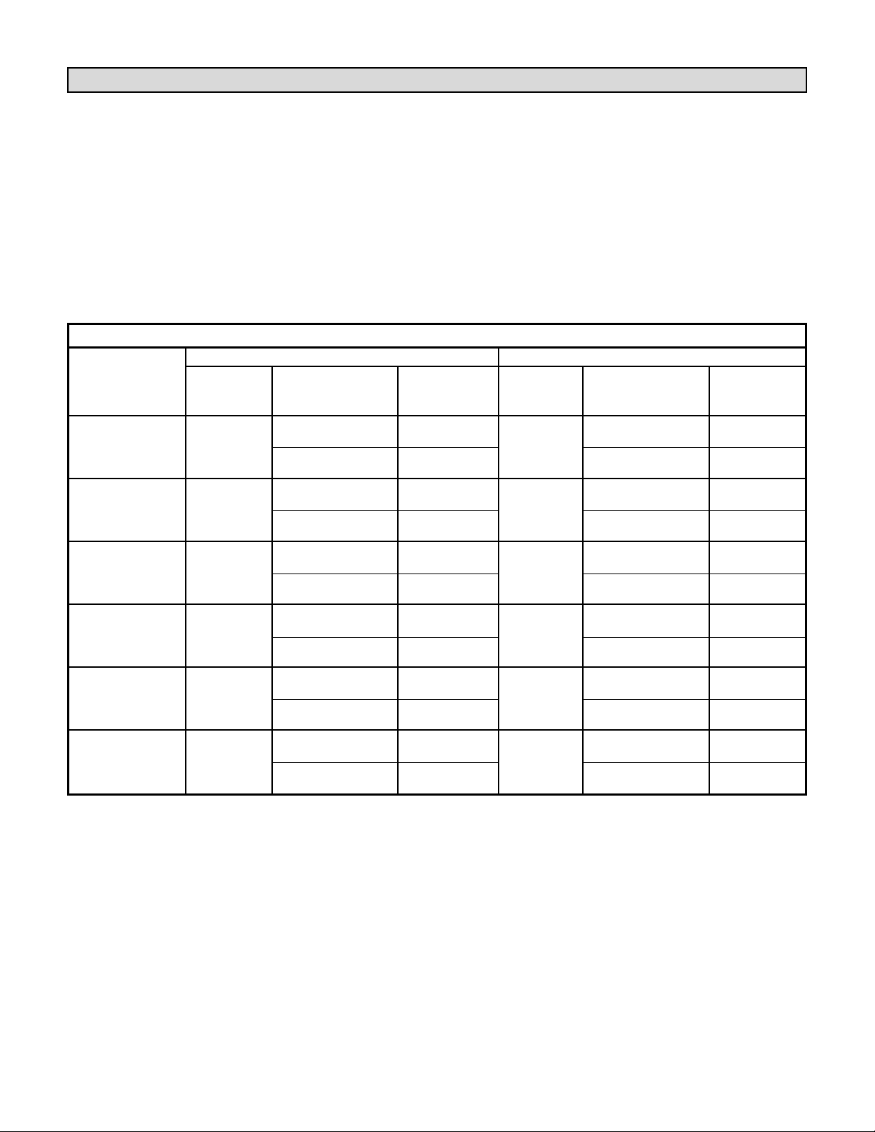
TABLE 2 – THERMOSTAT REQUIREMENTS
ZONE 1 ZONES 2-4
Recommended Recommended
Type
Terminals
Thermostats Type
Terminals
Thermostats
(see Tables 2a & 2b)
(see Table 2c)
(see Tables 2a & 2b)
(see Table 2c)
Any Zone,
HEAT/COOL
R, C, W, Y, G 1, 2
HEAT/COOL
R, C, W, Y, G 1, 2
Heat Cool
Optional: W2 and Y2 3, 4, 7 Optional: W2 and Y2 3, 4, 7
Zone 1,
HEAT/COOL
R, C, W, Y, G, O, B 1, 2
HEAT/COOL
R, C, W, Y, G 1, 2
Heat Cool
Optional: W2 and Y2 3, 4, 7 Optional: W2 and Y2 3, 4, 7
Any Zone,
HEAT/COOL
R, C, W, Y, G 1, 2
HEAT/COOL
R, C, W, Y, G 1, 2
Heat Pump,
Optional: W2 and Y2 3, 4, 7 Optional: W2 and Y2 3, 4, 7
Aux Heat Timer > 0
Zone 1,
HEAT/COOL
R, C, W, Y, G, O, B 1, 2
HEAT/COOL
R, C, W, Y, G 1, 2
Heat Pump
Optional: W2 and Y2 3, 4, 7 Optional: W2 and Y2 3, 4, 7
Any Zone,
Heat Pump,
HEAT PUMP
R, C, W1, Y1, G, O 8
HEAT PUMP
R, C, W1, Y1, G, O 8
Electric,
Optional: Y2 5, 6 Optional: Y2 5, 6
Aux Heat Timer = 0
Any Zone,
Heat Pump,
HEAT PUMP
R, C, W1, Y1, G, O 5, 6
HEAT PUMP
R, C, W1, Y1, G, O 5, 6
Gas,
Optional: Y2 5, 6 Optional: Y2 5, 6
Aux Heat Timer = 0
CONTROL PANEL
SET-UP
DIP SWITCH
POSITIONS
Thermostat Selection Guide
The position of the HEAT PUMP / HEAT/COOL switch,
the ZONE 1 / ANY ZONE switch and the AUX.
MINUTES switch (see DIP Switch Settings section) will
determine the thermostat requirements for each zone.
Any 24-volt electronic thermostat with a “C” (24VAC
common) connection can be used. Do not use
mechanical or power robbing thermostats. Power
robbing thermostats can cause unintended operation –
DO NOT use power robbing thermostats. Use Table 2
to determine which thermostat is required:
Page 6
Installation (continued)
TABLE 2c – RECOMMENDED THERMOSTATS
1 SignatureStat 1H/1C Non-Heat Pump (51M26)
1
2 Elite 1H/1C Non-Heat Pump (49M55)
3 SignatureStat 2H/2C Non-Heat Pump (51M27)
1
4 Elite 2H/2C Non-Heat Pump (49M56)
5 SignatureStat 2H/2C Heat Pump (51M28)
1
6 Elite 2H/2C Heat Pump (49M57)
7 T8624D2079 2H/2C Non-Heat Pump (37L61)
8 T8611G2101 2H/1C Heat Pump (37L60)
1
When using the SignatureStat, only the basic
modes of dehumidification and humidification
can be used.
TABLE 2a – HEAT/COOL TERMINAL DEFINITIONS
Thermostat
Terminal Function
R 24 VAC Hot
C 24 VAC Common
W 1st Stage Heat
W2 2nd Stage Heat
Y 1st Stage Cool
Y2 2nd Stage Cool
GFan
O Cooling Mode
B Heating Mode
TABLE 2b – HEAT PUMP TERMINAL DEFINITIONS
Thermostat
Terminal Function
R 24 VAC Hot
C 24 VAC Common
Y1 1st Stage Compressor
Y2 2nd Stage Compressor
W1 Auxiliary Heat
GFan
O Reversing Valve – Cool
B Reversing Valve – Heat
Tables 3 - 5 on the following pages detail how the zone
panel will respond to specific thermostat input terminals
being energized when set up in different DIP switch
configurations. Refer to the setup flowchart to determine
which DIP switch settings to use with your system.
Page 7
Installation (continued)
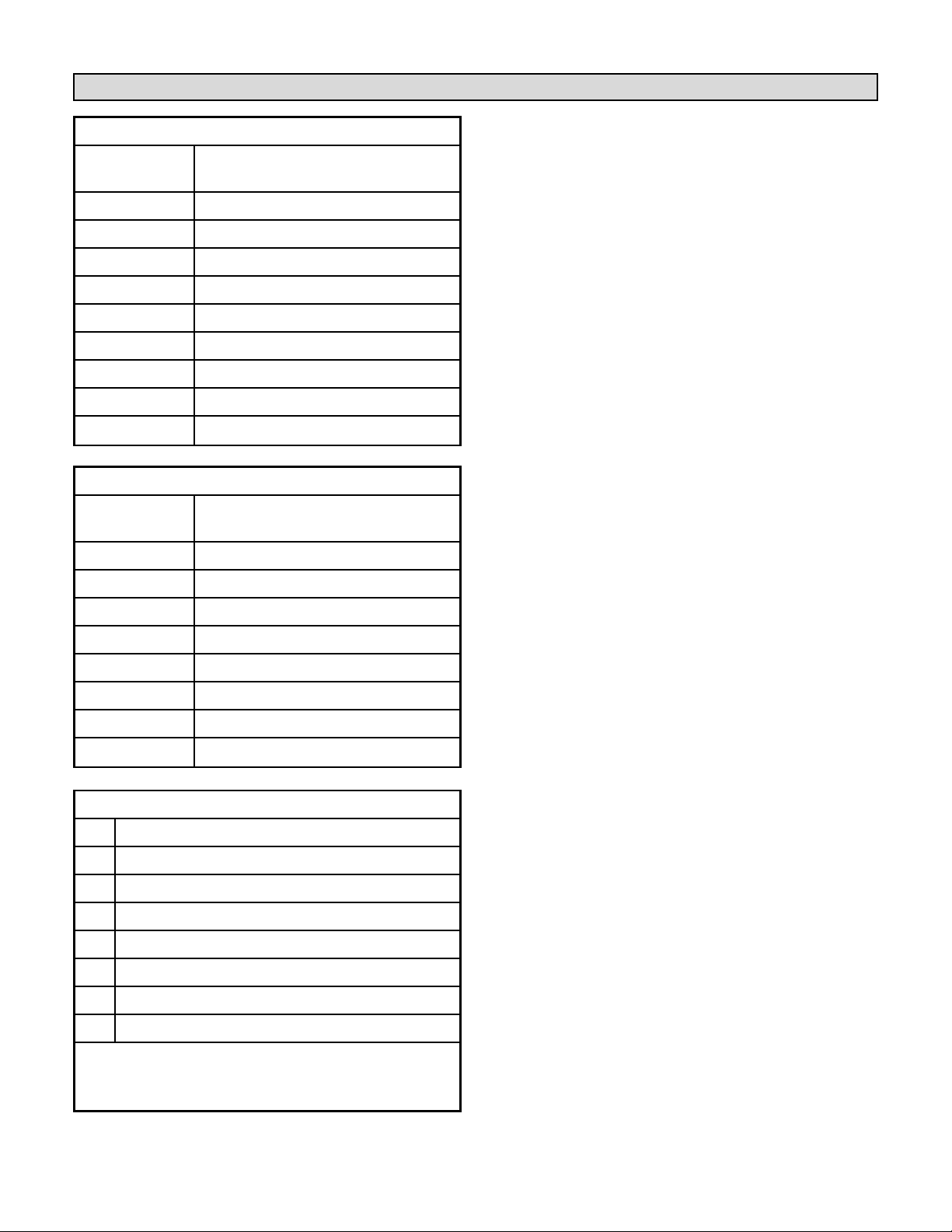
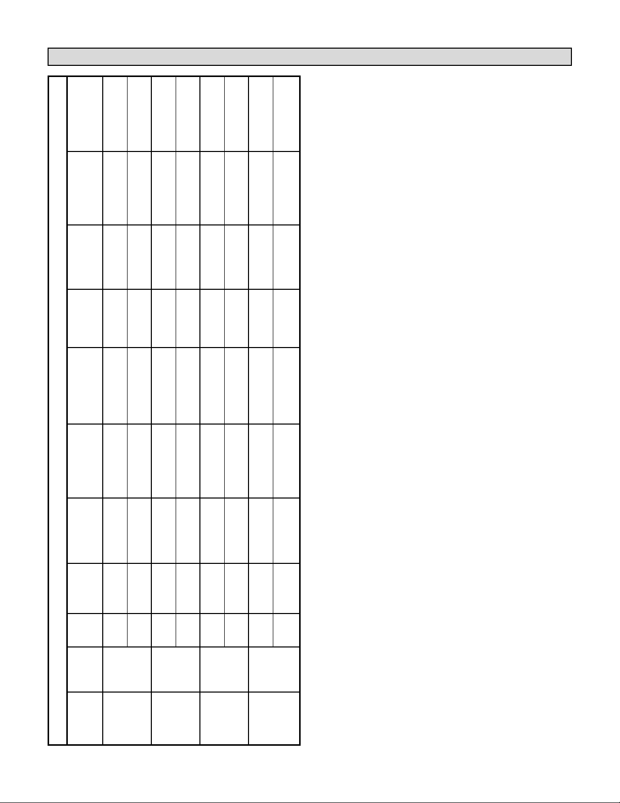
TABLE 3 – CONDENSING UNIT AND FURNACE SETUP OPTIONS
Input/ First Stage Second Stage
First Stage Second Stage First Stage Second Stage
Auxiliary Emergency
Setup
1
Stat Type
output Cool Cool
Gas or Electric Gas or Electric Compressor Compressor
Heat Heat
Furnace Furnace Heat Heat
Heat/Cool
Panel
Y+G
Y+2S+G or
W
W+2S or by
–– – –
Gas
Heat/Cool
Input by Stage Timer Stage Timer
Any Zone
Panel
Y1+O+G Y1+Y2+O+G W1+B W1+W2+B –– – –
Output
Heat/Cool
Panel
Y+O+G
Y+2S+O+G or
W+B
W+B+2S or
–– – –
Gas
Heat/Cool
Input by Stage Timer by Stage Timer
Zone 1
Panel
Y1+O+G Y1+Y2+O+G W1+B W1+W2+B –– – –
Output
Heat/Cool
Panel
Y+G
Y+2S+G or
W
W+2S or
–– – –
Electric
Heat/Cool
Input by Stage Timer by Stage Timer
Any Zone
Panel
Y1+O+G Y1+Y2+O+G W1+B+G W1+W2+B+G –– – –
Output
Heat/Cool
Panel
Y+O+G
Y+2S+O+G or
W+B
W+B+2S or
–– – –
Electric
Heat/Cool
Input by Stage Timer by Stage Timer
Zone 1
Panel
Y1+O+G Y1+Y2+O+G W1+B+G W1+W2+B+G –– – –
Output
TABLE 4 – HEAT PUMP WITH ELECTRIC HEAT SETUP OPTIONS
Input/ First Stage Second Stage
First Stage Second Stage First Stage Second Stage
Auxiliary Emergency
Setup
1
Stat Type
output Cool Cool
Electric Electric Compressor Compressor
Heat Heat
Furnace Furnace Heat Heat
Heat Pump
Panel
Y+O+G
Y+2S+O+G or
––Y+G
Y+2S+G or by Y+W+G W or by
Electric Heat
Input by Stage Timer Stage Timer (+2S if applicable) Emergency Switch
Aux Min = 0 Pump
Panel
Y1+O+G Y1+Y2+O+G ––Y1+B+G Y1+Y2+B+G
Y1+W1+B+G
W1+W2+B+G
Any Zone
Output (+Y2 if applicable)
Heat Pump
Panel
Y+O+G
Y+2S+O+G or
––W+B
W+B+2S or by
–
By Emergency
Electric
Heat/Cool
Input by Stage Timer Stage Timer Switch Only
Aux Min = 0
Panel
Y1+O+G Y1+Y2+O+G ––Y1+B+G Y1+Y2+B+G – W1+W2+B+G
Zone 1
Output
Heat Pump
Panel
Y+G
Y+2S+G or
––W
W+2S or by By Aux Timer By Emergency
Electric
Heat/Cool
Input by Stage Timer Stage Timer Only Switch Only
Aux Min > 0
Panel
Y1+O+G Y1+Y2+O+G ––Y1+B+G Y1+Y2+B+G
Y1+W1+B+G
W1+W2+B+G
Any Zone
Output (+Y2 if applicable)
Heat Pump
Panel
Y+0+G
Y+2S+O+G or
––W+B
W+2S+B or By Aux Timer By Emergency
Electric
Heat/Cool
Input by Stage Timer by Stage Timer Only Switch Only
Aux Min > 0
Panel
Y1+O+G Y1+Y2+O+G ––Y1+B+G Y1+Y2+B+G
Y1+W1+B+G
W1+W2+B+G
Zone 1
Output (+Y2 if applicable)
Page 8
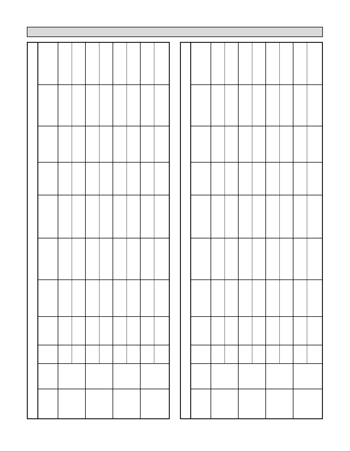
TABLE 5 – HEAT PUMP WITH GAS FURNACE SETUP OPTIONS
Input/ First Stage Second Stage
First Stage Second Stage First Stage Second Stage
Auxiliary Emergency
Setup
1
Stat Type
output Cool Cool
Gas Gas Compressor Compressor
Heat Heat
Furnace Furnace Heat Heat
Heat Pump
Panel
Y+O+G
Y+2S+O+G or Y+W+G W or by
Y+G
Y+2S+G or by
––
Gas Heat
Input by Stage Timer (+2S if applicable) Emergency Switch Stage Timer
Aux Min = 0 Pump
Panel
Y1+O+G Y1+Y2+O+G W1+B W1+W2+B Y1+B+G Y1+Y2+B+G ––
Any Zone
Output
Heat Pump
Panel
Y+O+G
Y+2S+O+G or
–
By Emergency
W+B
W+B+2S or by
––
Gas
Heat/Cool
Input by Stage Timer Switch Only Stage Timer
Aux Min = 0
Panel
Y1+O+G Y1+Y2+O+G – W1+W2+B Y1+B+G Y1+Y2+B+G ––
Zone 1
Output
Heat Pump
Panel
Y+G
Y+2S+G or By Aux Timer By Emergency
W
W+2S or by
– –
Gas
Heat/Cool
Input by Stage Timer Only Switch Only Stage Timer
Aux Min > 0
Panel
Y1+O+G Y1+Y2+O+G W1+B W1+W2+B Y1+B+G Y1+Y2+B+G – –
Any Zone
Output
Heat Pump
Panel
Y1+0+G
Y+2S+O+G or By Aux Timer By Emergency
W+B
W+B+2S or
– –
Gas
Heat/Cool
Input by Stage Timer Only Switch Only by Stage Timer
Aux Min > 0
Panel
Y1+O+G Y1+Y2+O+G W1+B W1+W2+B Y1+B+G Y1+Y2+B+G – –
Zone 1
Output
Installation (continued)
1
These charts apply when the # of Zones to Stage DIP switch is set to 1. If the Zone to Stage switch is set to greater than 1, the second stage
conditioning will only be brought on if the number of zones calling for the same conditioning call is greater than or equal to the DIP switch setting.
Page 9
Installation (continued)
Bypass Damper Sizing
7. Install the dampers. Power close, spring open
dampers are preferred. Refer to the instructions
provided with the damper.
18 AWG thermostat wire minimum recommended.
8. Re-install the cover on the base.
When fewer than the maximum number of zones are
calling for heating or cooling, an excess volume of air is
delivered, and because of the excess air, an excess
amount of static pressure is produced as well. Zone
systems often require a bypass duct to relieve this
pressure. A properly sized barometric bypass damper
must be installed in the bypass duct which is run
between the supply and return air duct systems (see
Figure 4). The barometric damper and the bypass duct
must be sized to accommodate the excess static
pressure from the supply duct.
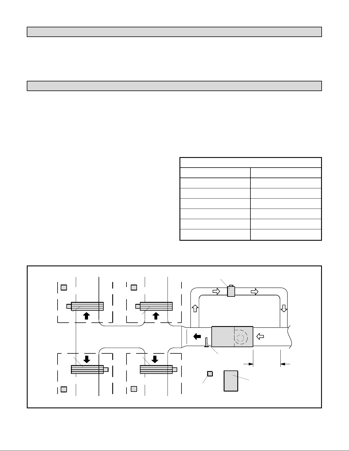
The bypass tap in the return air duct must be at least 6
ft. from the furnace /air handler to ensure that the hot or
cold air coming off of the plenum has time to mix with
the return air before it passes through the air handler
again. The provided discharge air sensor (field installed)
protects the equipment from overheating or coil
freeze-up by interrupting the HVAC equipment.
The bypass damper and duct should be sized to handle
the excess pressure created when the smallest zone is
operating alone (worst case). To size the bypass
damper, subtract the total air volume capacity of the
smallest zone from the total air volume of the system.
Example:
Total System air volume: 2000 cfm
Air volume of smallest zone: 600 cfm
Bypass requirement: 2000 - 600 = 1400 cfm
In this example, the bypass duct should be sized to
handle the 1400 cfm excess pressure created when
only the smallest zone has a demand. For bypass
damper air volume capacities, see Table 6.
Refer to the parts and supplies catalog for information
on available barometric bypass dampers.
FIGURE 4 – BYPASS DAMPER INSTALLATION
TABLE 6
Round Rectangular
8 in. dia. – 400 cfm 12 x 8 – 1000 cfm
10 in. dia. – 750 cfm 12 x 10 – 1200 cfm
12 in. dia. – 1200 cfm 12 x 12 – 1400 cfm
14 in. dia. – 1800 cfm 20 x 8 – 1600 cfm
16 in. dia. – 2400 cfm 20 x 10 – 2000 cfm
20 x 12 – 3000 cfm
IMPORTANT: Bypass duct should be mounted as far away
from the heating cooling unit as possible to allow for a
better mix of the bypass air with the return air.
ZONE 2 ZONE 1
ZONE 2
THERMOSTAT
ZONE
DAMPER
ZONE
DAMPER
ZONE 3
THERMOSTAT
ZONE 3 ZONE 4
BYPASS
DAMPER
ZONE 1
THERMOSTAT
ZONE
DAMPER
ZONE
DAMPER
ZONE 4
THERMOSTAT
SUPPLY
AIR
TRANSFORMER
FOR
PANEL, DAMPERS
AND THERMOSTATS
HEATING/
COOLING
UNIT
DISCHARGE
AIR SENSOR
BYPASS DUCT
6 ft. (1.8 m)
CONTROL
PA NE L
RETURN
AIR
 Loading...