

Lennox LT-B3661CL, LT-B3621CL, LT-B3021HL, LT-B3621HW, LT-B3621CW Installation Operating & Maintenance Manual
...
INSTALLATION
OPERATING &
MAINTENANCE MANUAL
SPLIT CASSETTE
English
June 2002

REFERENCE EQUIVALENCE :
LENNOX REFERENCE FACTORY NUMBER
DHA 28 LT-B2861HL


Contents
Functions................................................................................................................................ 3
Product Specifications (Cooling & Heating)........................................................................ 5
Dimensions............................................................................................................................. 8
Refrigeration Cycle Diagram............................................................................................... 11
Wiring Diagram..................................................................................................................... 13
Operation Details ................................................................................................................. 19
Installation of Indoor, Outdoor Unit.................................................................................... 22
Test Running ........................................................................................................................ 34
Cycle...................................................................................................................................... 36
Cycle Troubleshooting Guide.............................................................................................. 39
Electronic Parts Troubleshooting Guide............................................................................ 40
Electronic Control Device.................................................................................................... 44
Schematic Diagram.............................................................................................................. 45
Exploded View and Replacement Parts List...................................................................... 47
–2–
Functions
• Room temperature sensor. (Thermistor)
• Maintains the room temperature in accordance with the Setting Temp.
• Indoor fan is delayed for 5 seconds at the starting.
• Restarting is inhibited for approx. 3 minutes.
• High, Med, Low
• Intermittent operation of fan at low speed.
• The louver can be set at swing up and down automatically.
• Although the air-conditioner is turned off by a power failure, it is restarted automatically previous operation
mode after power supply.
• The setting temperature and desired operation mode are automatically set by fuzzy rule.
• Both the indoor and outdoor fan stops during defrosting.
• Hot start after defrost ends.
• The indoor fan stops until the evaporator piping temperature will be reached at 28°C.
Indoor Unit
Operation ON/OFF by Remote controller
Sensing the Room Temperature
Room temperature control
Starting Current Control
Time Delay Safety Control
Indoor Fan Speed Control
Soft Dry Operation Mode
Airflow Direction Control
Auto Operation
Deice (Defrost) control (Heating)
Hot-start Control (Heating)
Auto Restart
–3–
–4–
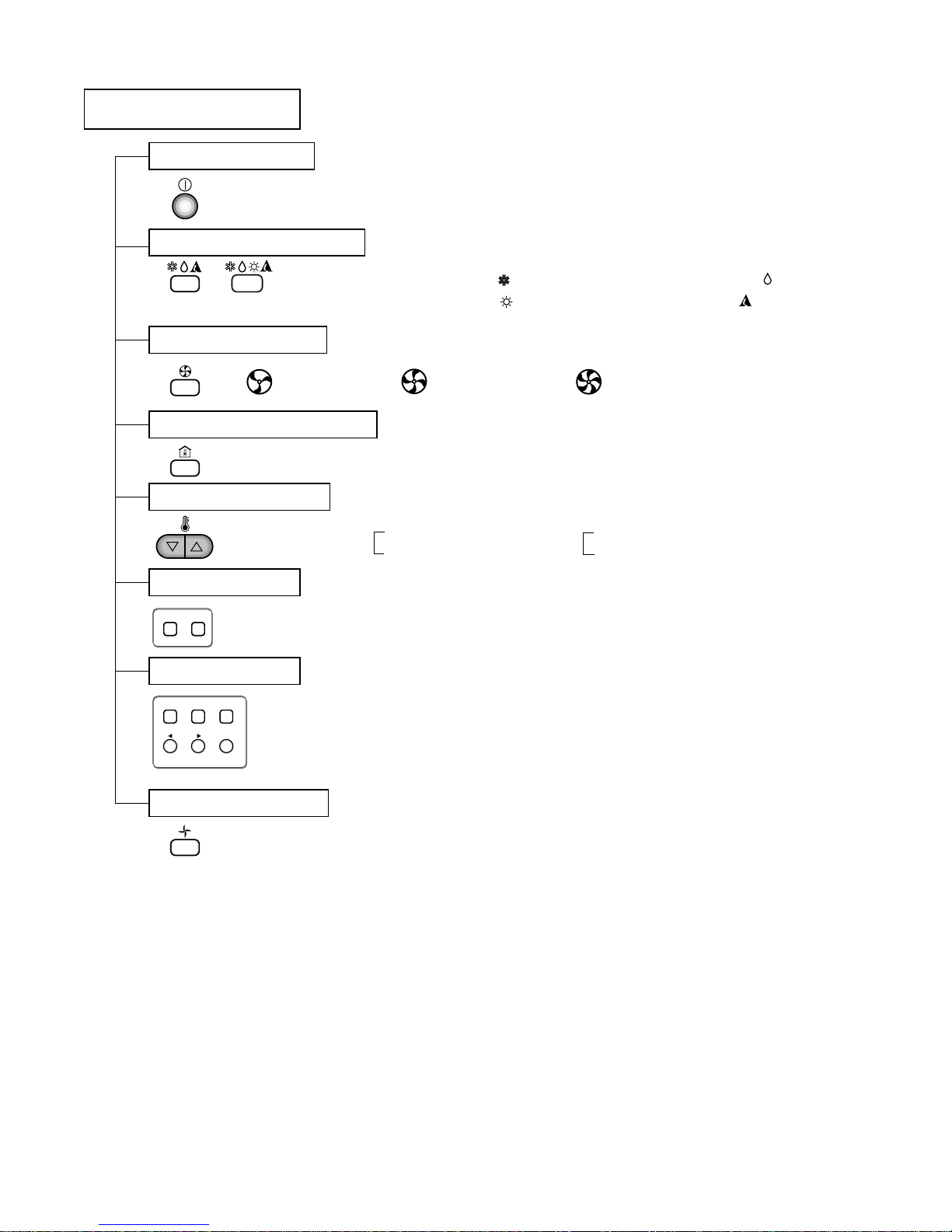
Remote Controller
Operation ON/OFF
Operation Mode Selection
Fan Speed Selection
Room Temperature Display
Temperature Setting
Setting the Timer
Weekly Timer
(Cooling
model only)
(Heating
model only)
(Low) (Med) (High)
Cooling Operation Mode ( )
Heating Operation Mode ( ) Auto Operation Mode ( )
Soft Dry Operation Mode ( )
Fan Operation Mode
HIMEDLO
Program Holiday
SET/CLR
MinHour
Week
Timer CancelTimer Cancel
: High:39°C ↔ LOW:11°C
: Fan Operates without cooling & heating
Cooling
Heating
Down to 18°C
Up to 30°C
Down to 16°C
Up to 30°C
Product Specifications (Cooling & Heating)
1. 60Hz
Model Name
Item Unit
Cooling Capacity Btu/h(kcal/h)
Heating Capacity Btu/h(kcal/h)
Moisture Removal l/h
Power Source Ø, V, Hz
Indoor
Outdoor
Input
Cooling
Heating
Running Current
Cooling
Heating
E.E.R. Btu/h-W
Indoor
Outdoor
Net Weight
Indoor
kg
Outdoor
Refrigerant (R-22) g
Airflow Direction Control (Up & Down)
Remocon Type
Liquid
Gas
Drain Hose
Connecting Wire
Main Power Cable
Time Delay Safety Function
Air Circulation
Soft Dry
Fan Speed (Indoor)
Timer
Self-Diagnosis
Air Circulation
m3/min
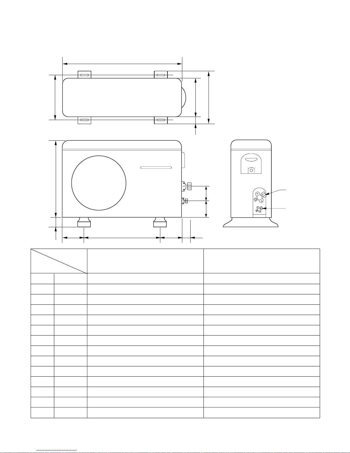
Dimensions
(W×H×D)
mm
W
A
LT-
B2421CL
24,000(6,048)
–
3.5
17
50
2,700
–
12.5
–
8.89
60
2,000
24,000(6,048)
24,000(6,048)
3.5
17
50
2,700
2,400
12.5
10.5
8.89
61
1,870
28,000(7,056)
–
4.0
19
52
2,850
–
12.8
–
9.82
60
2,150
30,000(7,560)
–
4.3
19
52
2,850
–
12.8
–
10.53
60
2,150
30,000(7,560)
30,000(7,560)
4.3
19
52
2,850
2,750
12.8
12.3
10.53
65
2,400
28,000(7,056)
28,000(7,056)
4.0
19
52
2,850
2,750
12.8
12.3
9.82
65
2,400
LT-
B2421HL
LT-
B2821CL
LT-
B3021CL/CW
LT-
B2821HL
LT-
B3021HL/HW
–5–
Service Valve &
Connecting Tube
870 x 800 x 320
800 x 800 x 298(910 x 910 x 30)
35(30+5)
1Ø, 220V, 60Hz
870 x 655 x 320
O
Wired Remocon, Wireless Remocon(Optional)
3/8"(9.52)
5/8"(15.88)
O
0.75mm2↑
2.5mm2↑
O
O
O
3(Hi, Med, Low)
24Hrs
O
–6–
Model Name
Item Unit
Cooling Capacity Btu/h(kcal/h)
Heating Capacity Btu/h(kcal/h)
Moisture Removal ℓ/h
Power Source , V, Hz
Indoor
Outdoor
Input Cooling
Heating
Running Current Cooling
Heating
E.E.R. Btu/h-W
Indoor
Outdoor
Net Weight
Indoor
kg
Outdoor
Refrigerant (R-22) g
Airflow Direction Control (Up & Down)
Remocon Type
Liquid
Gas
Drain Hose
Connecting Wire
Main Power Cable
Time Delay Safety Function
Air Circulation
Soft Dry
Fan Speed (Indoor)
Timer
Self-Diagnosis
Air Circulation
m
3
/min
Dimensions
(W×H×D)
mm
W
A
LT-B2461CL LT-B2461HL LT-B2861CL LT-B2861HL
24,000(6,048)
–
3.5
17
50
2,800
–
13.5
–
8.57
60
1,900
24,000(6,048)
24,000(6,048)
3.5
17
50
2,800
2,500
14
13
8.57
61
1,870
28,000(7,056)
–
4.0
19
52
2,850
–
13.4
–
9.82
60
2,100
28,000(7,056)
28,000(7,056)
4.0
19
52
2,850
2,650
13.4
12.6
9.82
65
2,400
Service Valve &
Connecting Tube
800 x 800 x 298(910 x 910 x 30)
1Ø, 220V~240V, 50Hz
35(30+5)
870 x 800 x 320
870 x 655 x 320
O
Wired Remocon, Wireless Remocon(Optional)
3/8"(9.52)
5/8"(15.88)
O
0.75mm2↑
2.5mm2↑
O
O
O
3(Hi, Med, Low)
24Hrs
O
2. 50Hz
–7–
Model Name
Item Unit
Cooling Capacity Btu/h(kcal/h)
Heating Capacity Btu/h(kcal/h)
Moisture Removal l/h
Power Source Ø, V, Hz
Indoor
Outdoor
Input Cooling
Heating
Running Current Cooling
Heating
E.E.R. Btu/h-W
Indoor
Outdoor
Net Weight
Indoor
kg
Outdoor
Refrigerant (R-22) g
Airflow Direction Control (Up & Down)
Remocon Type
Liquid
Gas
Drain Hose
Connecting Wire
Main Power Cable
Time Delay Safety Function
Air Circulation
Soft Dry
Fan Speed (Indoor)
Timer
Self-Diagnosis
Air Circulation
m3/min
Dimensions
(W×H×D)
mm
W
A
LT-
B3681CL
36,000(9,072)
–
5.0
22
58
4,300
–
7.5
–
–
80
3,150
36,000(9,072)
36,000(9,072)
5.0
22
58
4,300
4,100
7.5
7.0
–
81
3,150
36,000(9,072)
–
5.0
22
58
4,400
–
22
–
–
80
3,150
36,000(9,072)
36,000(9,072)
5.0
22
58
4,400
4,100
22
21
–
81
3,150
36,000(9,072)
36,000(9,072)
5.0
22
58
4,000
3,800
18
17
–
81
3,000
36,000(9,072)
–
5.0
22
58
4,000
–
18
–
–
80
3,150
LT-
B3681HL
LT-
B3661CL
LT-
B3661HL
LT-
B3621CL/CW
LT-
B3621HL/HW
Service Valve &
Connecting Tube
800 x 800 x 298(910 x 910 x 30)
35(30+5)
3Ø, 380-415V, 50Hz
1Ø, 220-240V, 50Hz
1Ø, 220V, 60Hz
790 x 965 x 320
O
Wired Remocon, Wireless Remocon(Optional)
3/8"(9.52)
3/4"(19.05)
O
0.75mm2↑
2.5mm2↑ 3.5mm2↑
O
O
O
3(Hi, Med, Low)
24Hrs
O
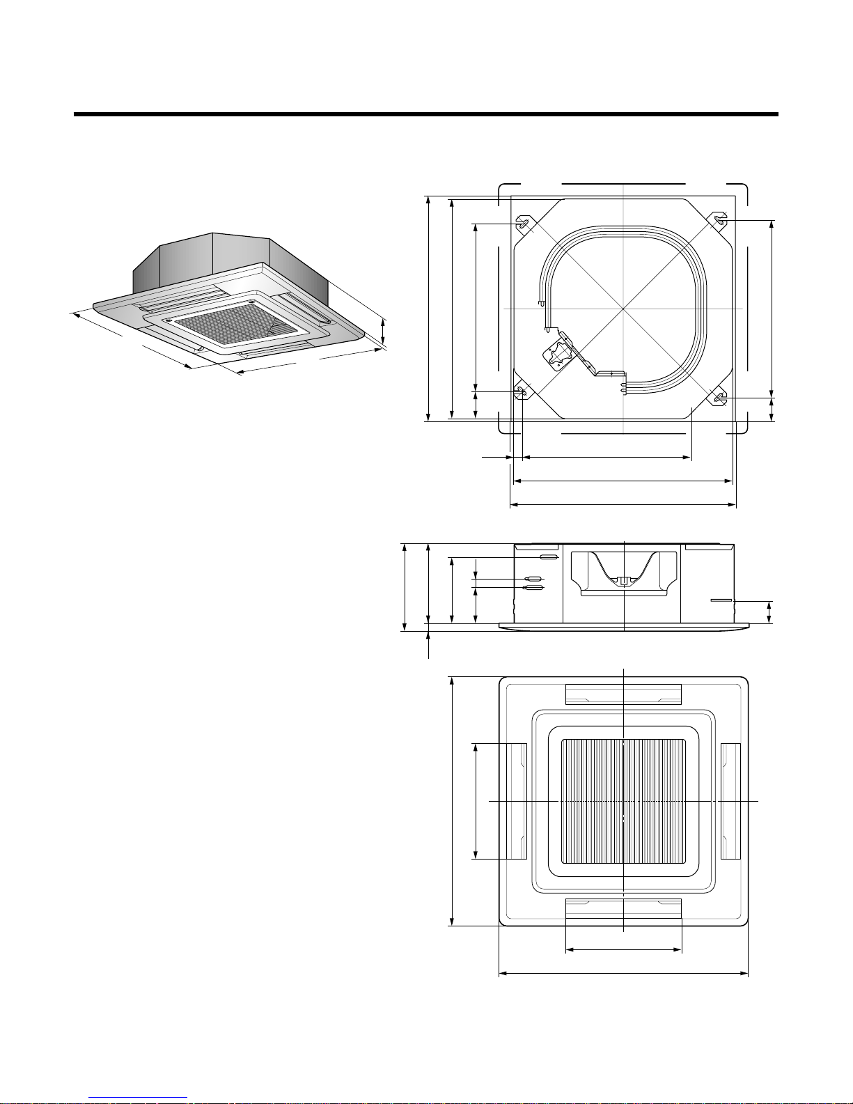
Dimensions
Indoor Unit
910
910
298
707
800
600113
65075
100
145423
910 255
29830
(328)
30
800
840
840
423
910
–8–
–9–
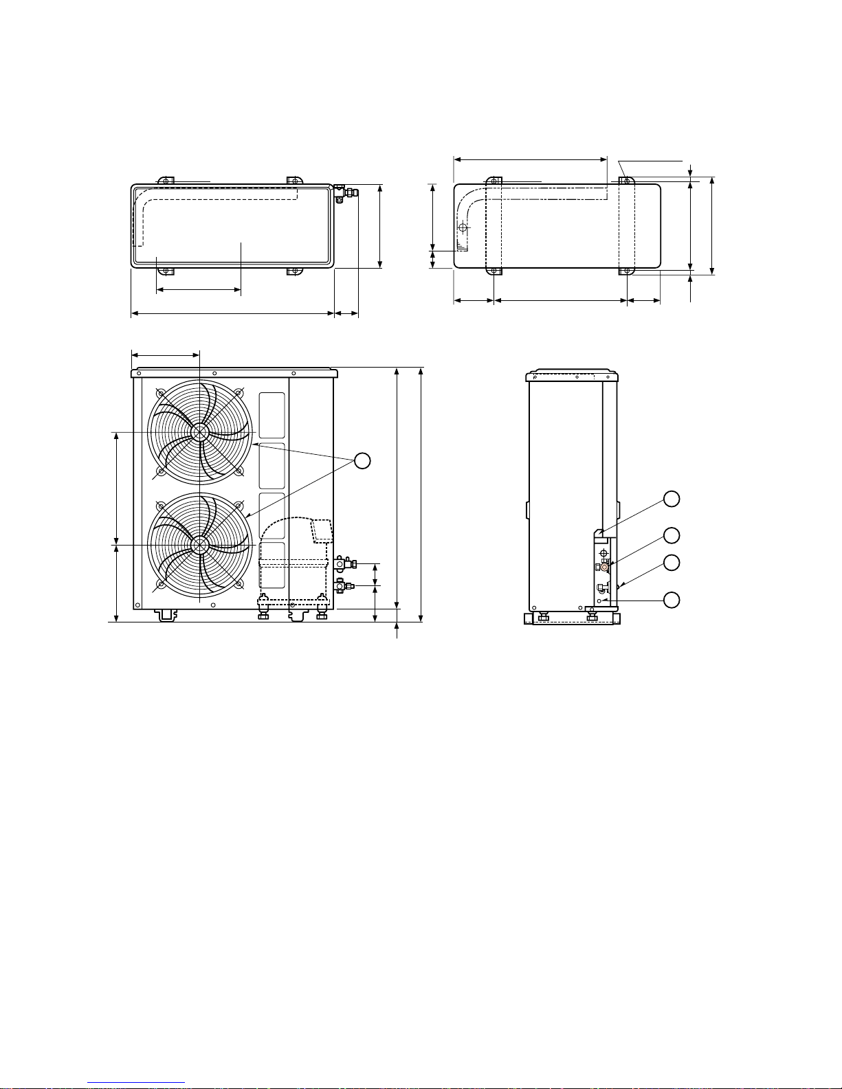
Outdoor Unit
Gas side
3-way valve
Liquid side
3-way valve
W
L6L7 L8 L9
L4
L11
L10
D
L1
L2
L5
L3
MODEL
DIM
W mm 870 870
H mm 655 800
D mm 320 320
L1 mm 370 370
L2 mm 25 25
L3 mm 340 340
L4 mm 630 775
L5 mm 25 25
L6 mm 546 546
L7 mm 162 162
L8 mm 162 162
L9 mm 54 54
L10 mm 74.5 74.5
L11 mm 79 79
LT-B2421CL/HL, LT-B2461CL/HL
LT-B2861CL, LT-B2821CL, LT-B3021CL/CW
LT-B2861HL, LT-B2821HL, LTB3021HL/HW
–10–
Outdoor Unit(LT-B3621CL/CW/HL/HW, B3661CL/HL, B3681CL/HL)
320
790
385
72
482
4-ø12Hole
249
71
145
500
145
10
334
354
10
265
440
925
965
130
40
80
292.5
5
3
1
2
4
(Air intake vent)
(Air intake vent)
(Air intake vent)
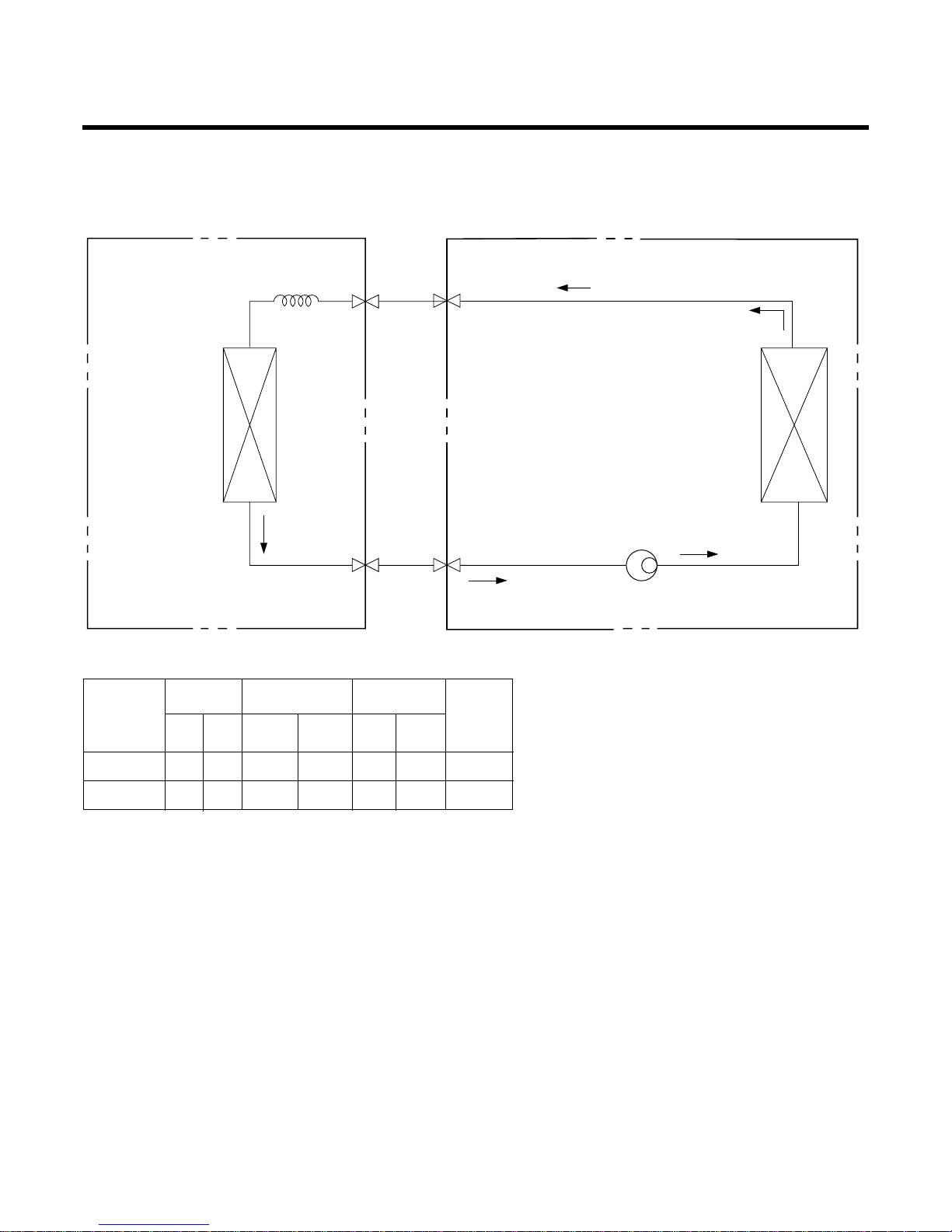
Refrigeration Cycle Diagram
• COOLING ONLY
• Rated performance for refrigerant line length of: 5m
• If 24K or 28K Model is installed at a distance of 15m, 500g of refrigerant
should be added ....................................................(15-5)x50g
MODEL
24K, 28K, 30K BTU
5/8" 3/8" 5 20
36
K BTU
3/4" 3/8" 5 25
GAS LIQUID
515 50
520 70
Elevation B(m)
Length A(m)
* Additional
refrigerant
(g/m)
Pipe Size
Rated Rated
Max. Max.
INDOOR UNIT OUTDOOR UNIT
HEAT
EXCHANGER
(EVAPORATOR)
HEAT
EXCHANGER
(CONDENSER)
COMPRESSOR
GAS SIDE
LIQUID SIDE
CAPILLARY TUBE
–11–
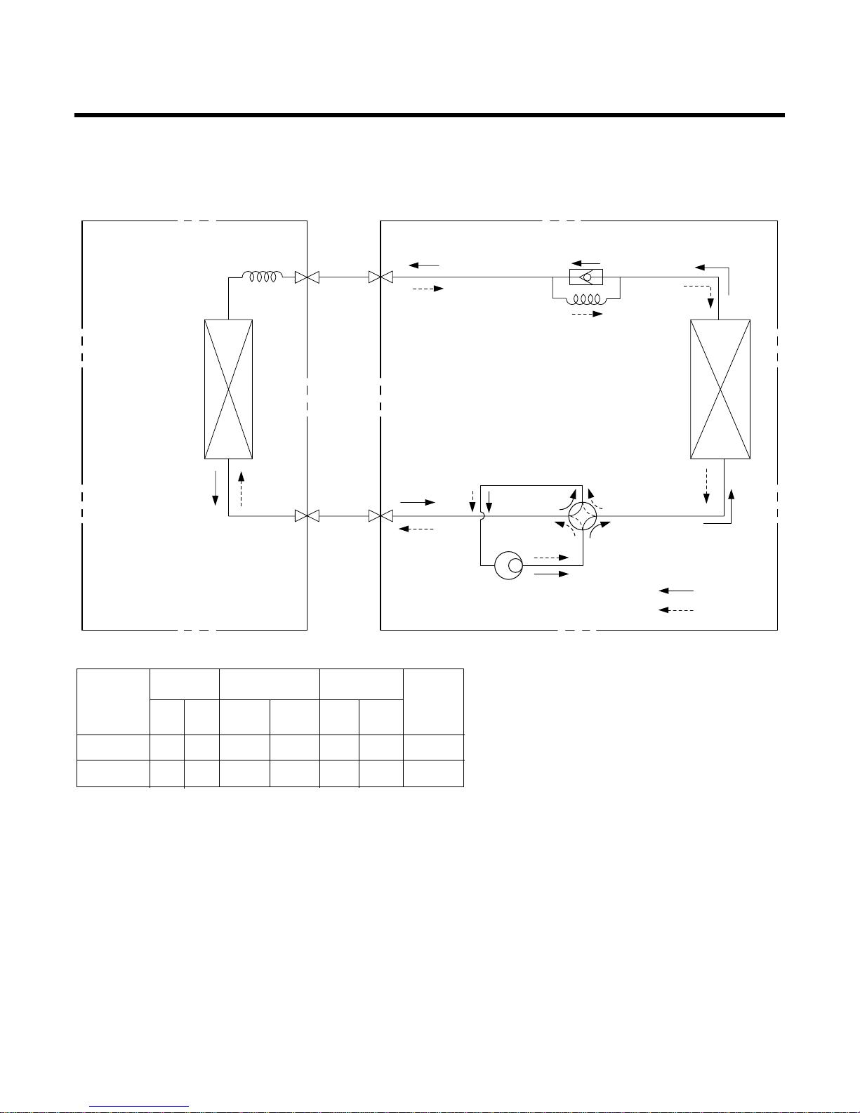
• HEAT PUMP
–12–
INDOOR UNIT OUTDOOR UNIT
HEAT
EXCHANGER
HEAT
EXCHANGER
COMPRESSOR
GAS SIDE
LIQUID SIDE
COOLING
HEATING
REVERSING
VALVE
CHECK VALVE
CAPILLARY TUBE
CAPILLARY TUBE
• Rated performance for refrigerant line length of: 5m
• If 24K or 28K Model is installed at a distance of 15m, 500g of refrigerant
should be added ....................................................(15-5)x50g
MODEL
24K, 28K, 30K BTU
5/8" 3/8" 5 20
36
K BTU
3/4" 3/8" 5 25
GAS LIQUID
515 50
520 70
Elevation B(m)
Length A(m)
* Additional
refrigerant
(g/m)
Pipe Size
Rated Rated
Max. Max.
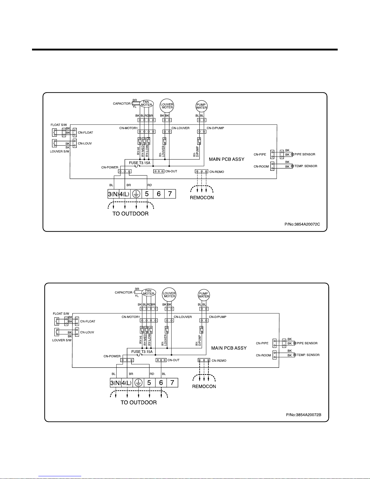
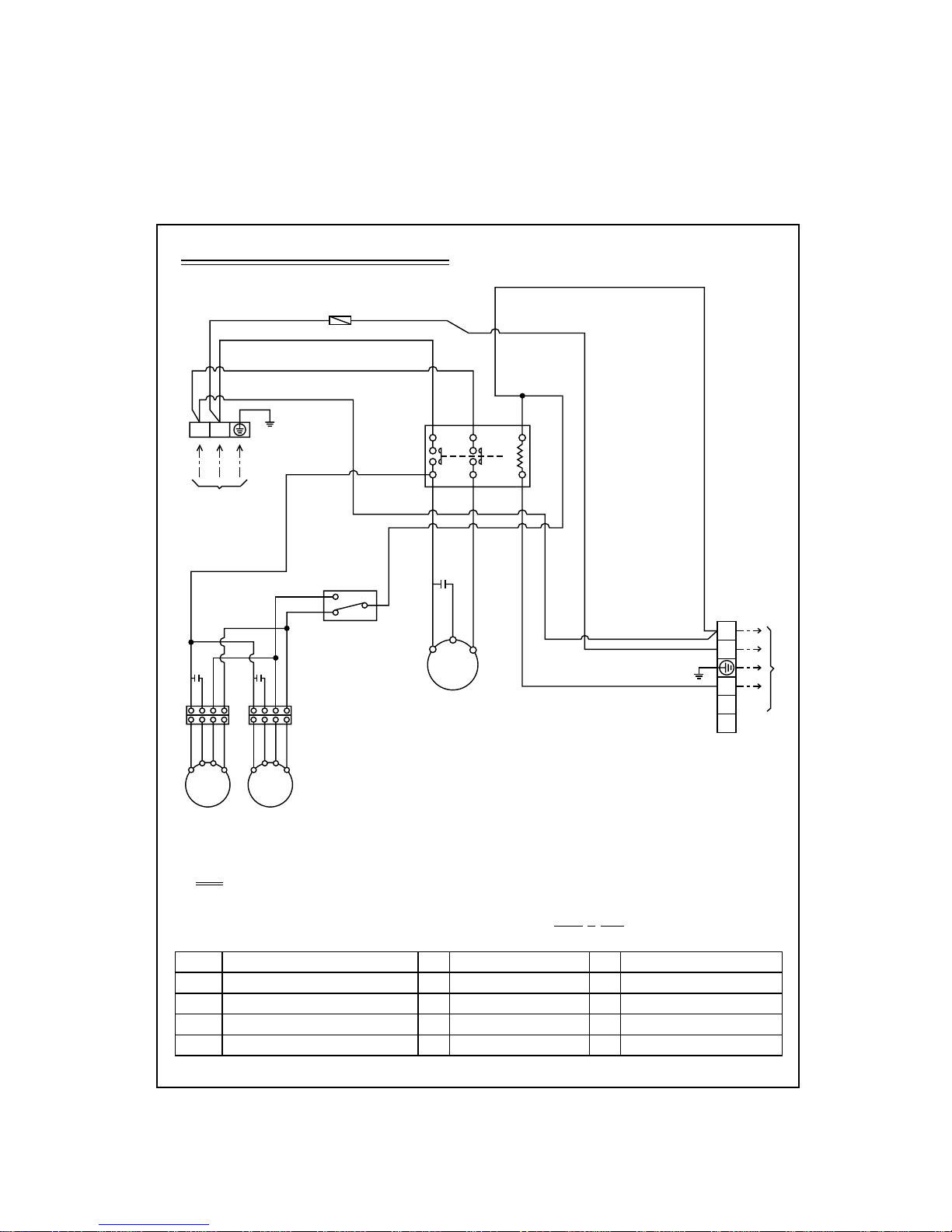
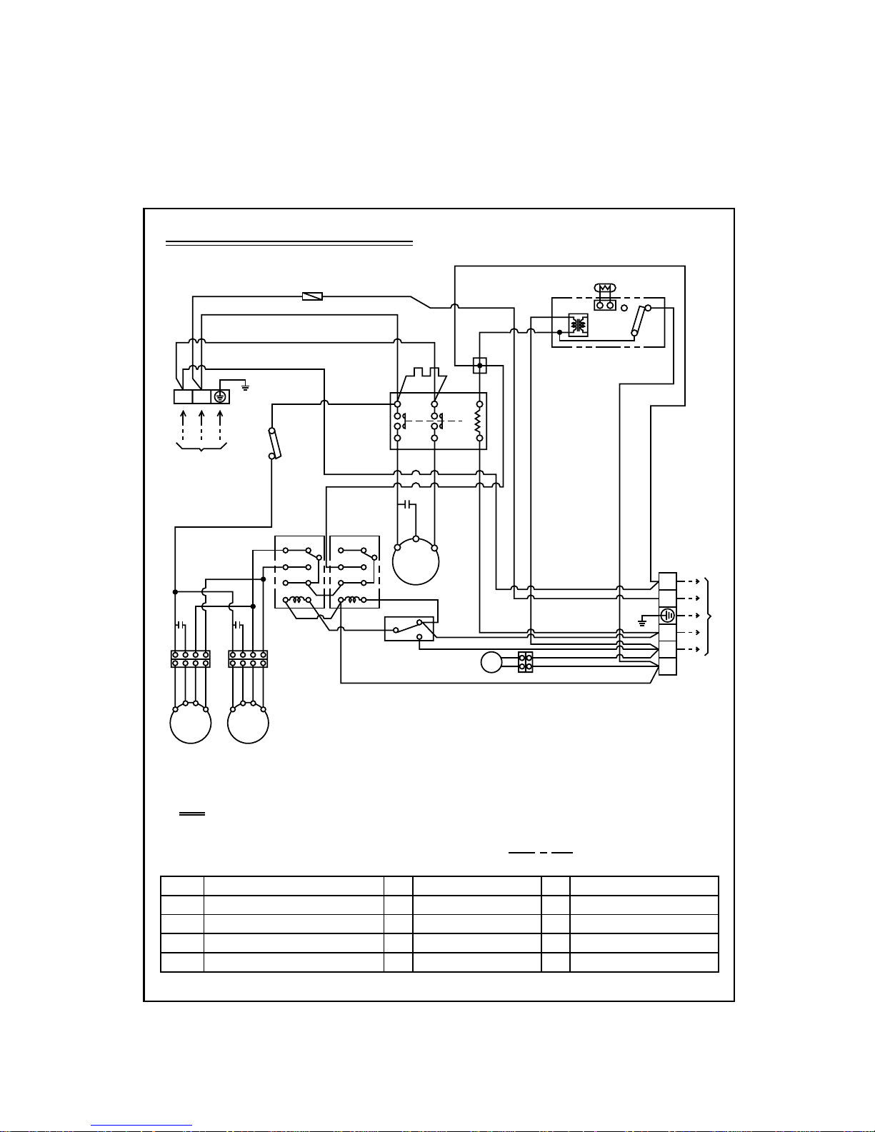
Wiring Diagram
(1) Indoor Unit
1. COOLING ONLY
2. HEAT PUMP
–13–
–14–
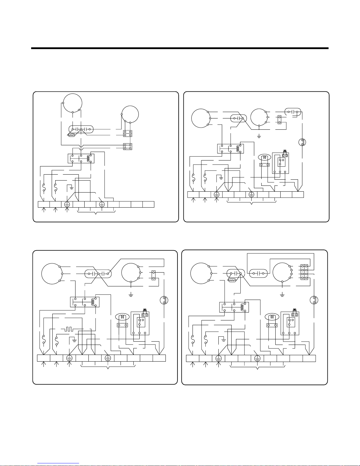
(2) Outdoor Unit
1. LT-B2461CL/B2861CL/B2421CL
B2821CL/B3021CL/B3021CW
2. LT-B2461HL/B2421HL
3. LT-B2861HL 4. LT-B2821HL/B3021HL/B3021HW
COMP.
MOTOR
R
S
C
RD
BL
BL
P.T.C
(OPTION)
BR
BR
BRBL
BL
BL
FUSE(5A)
FUSE(5A)
BL
YL
RD
POWER
RELAY
841
620
CAPACITOR
GN/YL
TO INDOOR
POWER INPUT
1(N)2(L
)
3(N)4(L
)
5678
TERMINAL
BLOCK
GN/YL
OR
BR
BK
BR
COMP.
MOTOR
R
S
C
BL
BR
BR
BR
BR
BL
BL
BKBK
WH
BL
CRANK CASE
HEATER
FUSE(5A)
FUSE(5A)
BL
RD
YL
BK
OR
OR
BK
BK
RD
REVERSING
COIL
BK
BK
YL
BL
POWER
RELAY
841
620
Capacitor
HIGH PRESSURE S/W
GN/YL
L1L2L3
GN/YL
TO INDOOR
POWER INPUT
1(N)2(L
)
3(N)4(L
)
5678
TERMINAL
BLOCK
3854A90002G
GN/YL
BK
COMP.
MOTOR
R
S
C
BL
BR
BR
BR
BRBL
BL
WH
BL
FUSE(5A)
FUSE(5A)
BL
RD
P.T.C
(OPTION)
BR
YL
OR
BK
BK
BK
BK
RD
REVERSING
COIL
BK
BK
YL
BL
POWER
RELAY
841
620
Capacitor
Capacitor
HIGH PRESSURE S/W
GN/YL
L1L2L3
GN/YL
TO INDOOR
POWER INPUT
1(N)2(L
)
3(N)4(L
)
5678
TERMINAL
BLOCK
3854A90002N
GN/YL
BK
COMP.
MOTOR
R
S
C
BL
BR
BR
BR
BRBL
BL
WH
BL
FUSE(5A)
FUSE(5A)
BL
RD
YL
OR
BK
BK
BK
BK
RD
REVERSING
COIL
BK
BK
YL
OR
BL
POWER
RELAY
841
620
Capacitor
Capacitor
HIGH PRESSURE S/W
GN/YL
L1L2L3
GN/YL
TO INDOOR
POWER INPUT
1(N)2(L
)
3(N)4(L
)
5678
TERMINAL
BLOCK
GN/YL
BK
–15–
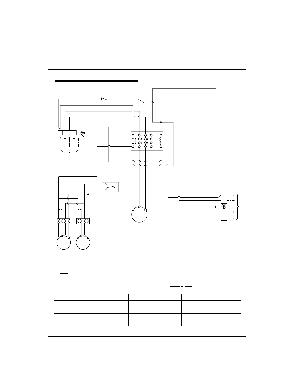
5. LT-B3681CL
THMO
C
H
L
TO INDOOR
Outdoor Unit Wiring Diagram
NOTE
BL : BLUE
BK : BLACK
BR : BROWN
OR : ORANGE GN/YL : GREEN/YELLOW
63H2
TMo
Co
HIGH PRESSURE SWITCH FOR HEATING
TERMINAL BLOCK
RUN CAPACITOR FOR FMo
TMCMMAIN TERMINAL BLOCK
COMPRESSOR
F1
FMo
FUSE (250V, 5A)
OUTDOOR FAN MOTOR
P/NO : 3854A30042P
RD : RED
WH : WHITE
YL : YELLOW
WIRING OF FIELD
(CONNECTING WIRE)
TM
3Ø, 380-415V
POWER SUPPLY
BK
52C
13531
24632
B
A
BK
WH
BK
WH
RD
BK
BK
RD
BL BK
WH
T1
T3
T2
CM
WH
WH
BL
BK
RSTN
Co
OR YLBLBK OR YLBLBK
Co
FMo1 FMo2
GN/YL
3(N)
4(L)
5
6
7
F1
–16–
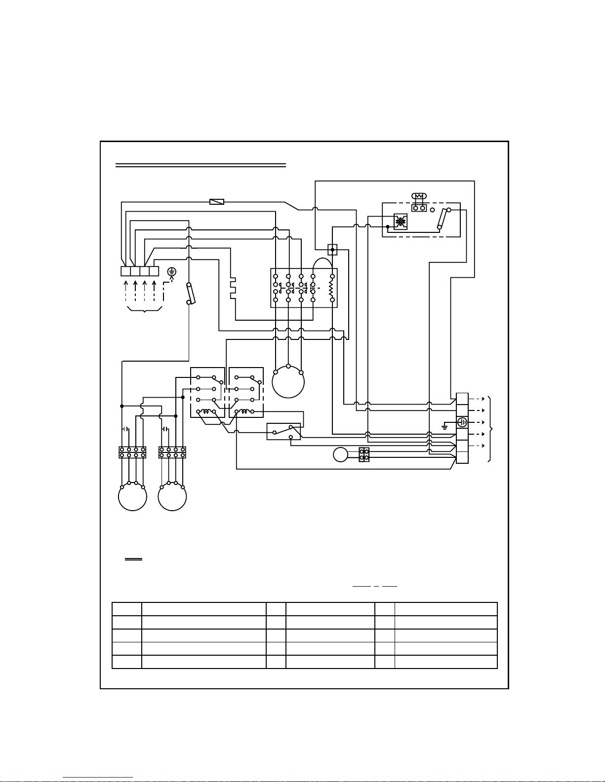
6. LT-B3681HL
Outdoor Unit Wiring Diagram
NOTE
BL : BLUE
BK : BLACK
BR : BROWN
OR : ORANGE GN/YL : GREEN/YELLOW
63H2
C TH
20SV
52C
TMo
HIGH PRESSURE SWITCH FOR HEATING
THERMISTOR FOR PIPE TEMP.
REVERSING COIL
MAGNECTIC CONTACTOR
TERMINAL BLOCK
TM
52F1
CM
Co
FMo
MAIN TERMINAL BLOCK
RELAY FOR FMo
COMPRESSOR
RUN CAPACITOR FOR FMo
OUTDOOR FAN MOTOR
F1
DP
CH1
THMO
52F2
FUSE (250V, 5A)
DEICER PCB
CRANK CASE HEATER FOR CM
THEMOSTAT FOR COOLING
RELAY FOR FMO CONTROL.
P/NO : 3854A30042H
RD : RED
WH : WHITE
YL : YELLOW
WIRING OF FIELD
(CONNECTING WIRE)
TM
3Ø, 380-415V
POWER SUPPLY
BK
63H2
52C
13531
24632
B
A
BK
WH
BK
TNS
NO
C TH
NC
D.P
WH
T/B1
BK
WH
WH
RD
BK
WH
BK
BK
RD
BL BK BK
WH
T1
T3
T2
CH1
CM
YL WH
WH
BL
BK
RSTN
Co
OR YLBLBK OR YLBLBK
Co
FMo1 FMo2
20SV
BKBKBK
BK
WH
YL
WH
YL
BL
BL
THMO
C
L
H
GN/YL
TOO INDOOR
3(N)
4(L)
5
6
7
78
52F2
12
34
56
78
52F1
12
34
56
F1
–17–
7. LT-B3621CL/B3621CW/B3661CL
Outdoor Unit Wiring Diagram
NOTE
BL : BLUE
BK : BLACK
BR : BROWN
OR : ORANGE GN/YL : GREEN/YELLOW
52C
TMo
Co
MAGNETIC CONTACTOR
TERMINAL BLOCK
RUN CAPACITOR FOR FMo
TM
CM
CR
MAIN TERMINAL BLOCK
COMPRESSOR
RUN CAPACITOR FOR CM
F1
FMo
FUSE (250V, 5A)
OUTDOOR FAN MOTOR
P/NO : 3854A30042N
RD : RED
WH : WHITE
YL : YELLOW
WIRING OF FIELD
(CONNECTING WIRE)
TM
POWER SUPPLY
BK
Cr
52C
BK
BK
L1T1L2T2B
A
WH
BK
WH
BK
WH
BL BK BK
RD
R
C
S
CM
WH
WH
GN/YL
WH
BL
BK
1(N)2(L
)
Co
OR YLBLBK OR YLBLBK
Co
FMo1 FMo2
THMO
C
H
L
GN/YL
TO INDOOR
3(N)
4(L)
5
6
7
F1
–18–
8. LT-B3621HL/B3621HW/B3661HL
Outdoor Unit Wiring Diagram
NOTE
BL : BLUE
BK : BLACK
BR : BROWN
OR : ORANGE GN/YL : GREEN/YELLOW
63H2
C TH
20SV
52C
Cr
HIGH PRESSURE SWITCH FOR HEATING
THERMISTOR FOR PIPE TEMP.
REVERSING COIL
MAGNECTIC CONTACTOR
RUN CAPACITOR FOR CM
TM
52F1
CM
Co
FMo
MAIN TERMINAL BLOCK
RELAY FOR FMo
COMPRESSOR
RUN CAPACITOR FOR FMo
OUTDOOR FAN MOTOR
F1
DP
CH1
THMO
52F2
FUSE (250V, 5A)
DEICER PCB
CRANK CASE HEATER FOR CM
THEMOSTAT FOR COOLING
RELAY FOR FMO CONTROL.
P/NO : 3854A30042L
RD : RED
WH : WHITE
YL : YELLOW
WIRING OF FIELD
(CONNECTING WIRE)
TM
POWER SUPPLY
BK
63H2
Cr
52C
CH1
BK
BK BK
BK
L1T1L2T2B
A
WH
BK
TNS
NO
C TH
NC
D.P
WH
T/B1
BK
WH
WH
BK
WH
BL BK BK
RD
R
C
S
CM
YL WH
WH
GN/YL
WH
BL
BK
1(N)2(L
)
Co
OR YLBLBK OR YLBLBK
Co
FMo1 FMo2
20SV
BKBKBK
BK
WH
YL
WH
YL
BL
BL
THMO
C
L
H
GN/YL
TO INDOOR
3(N)
4(L)
5
6
7
78
52F2
12
34
56
78
52F1
12
34
56
F1
–19–
Operation Details
(1) The function of main control
1. Time Delay Safety Control
• 3min The compressor is ceased for 3minutes to balance the pressure in the refrigeration cycle.
(Protection of compressor)
• 5sec
Vertical louvers are delayed for 5 secs to be opened to prevent the frictional sound between louver and air flow.
• 30sec The 4-way valve is ceased for 30sec. to prevent abnormal noise when the Heating operation is OFF or
switched to the other operation mode while compress is off.
While compressor is running, it takes 3~5 seconds to switch.
2. Auto Swing Control
• This function is to swing the louver up and down automatically.
3. Air-Filter Checking Control
• 'Filter' sign will appear on the remote controller display and main body display when an air-filter is polluted. Then
clean the air-filter referring to Owners Manual.
4. Soft-Dry Operation
• The indoor fan speed is automatically set to the low, and fan speed control is not available because of already
being set to the best speed for Dry Operation by Micom Control.
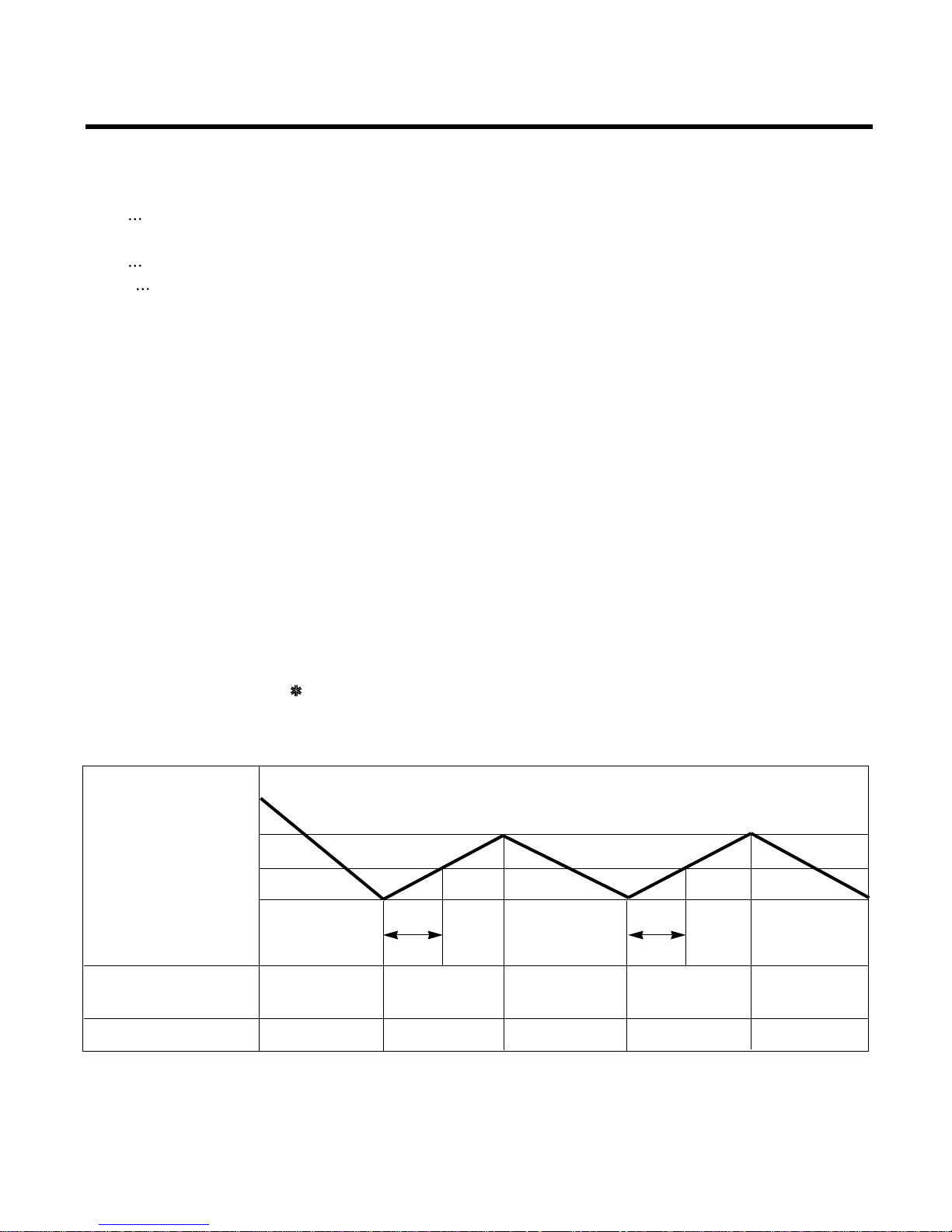
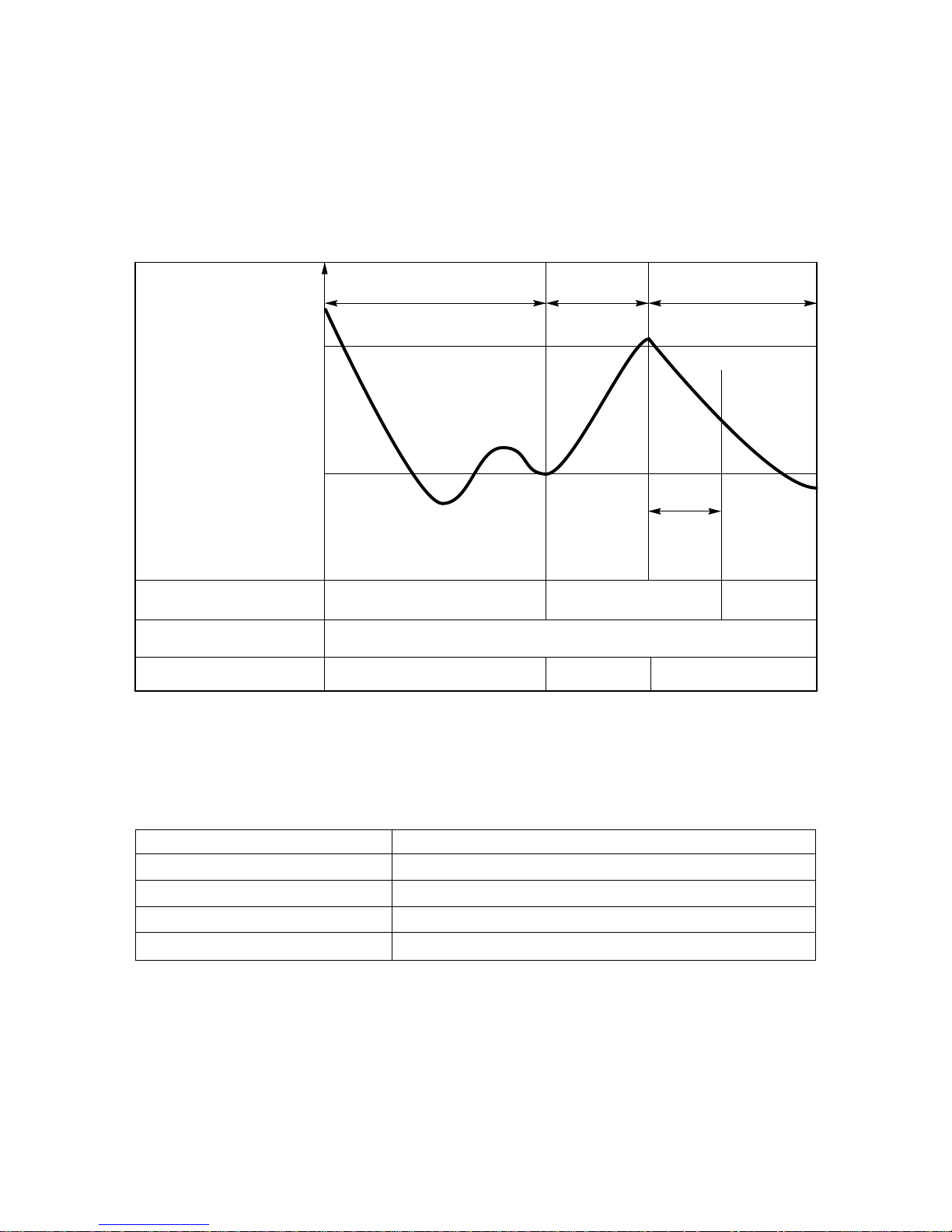
5. Cooling Mode Operation
• When selecting the Cooling( ) Mode Operation, the unit will operate according to the setting by the remote con-
troller and the operation diagram is as follows.
Intake Air temp.
SET TEMP.+0.5°C
(COMP. ON)
SET TEMP
SET TEMP. -0.5°C
(COMP. OFF)
Selected Selected Selected
fan speed fan speed fan speed
COMPRESSOR ON OFF ON OFF ON
INDOOR FAN Low Low
More than
3 minutes
More than
3 minutes
–20–
Intake Air temp.
Setting temp.+3°C
(Compressor OFF)
Setting temp.
(Compressor ON)
INDOOR FAN
COMPRESSOR ON OFF ON OFF
A point; While the indoor Heat-Exchanger temperature is higher than 40°C fan operates at low speed, when
it becomes lower than 40˚C fan stops.
B point; When the indoor Heat-Exchanger temperature is higher than 42°C, fan operates at selected fan
speed, when it becomes lower than 39°C, the fan operates at low speed.
6. Heating Mode Operation
The unit will operate according to the setting by the remote controller and the operation diagram is shown as follows.
(Hot Start)
Low
OFF
Selected
Fan Speed
minimum 3min
Selecting fan
speed
LowLowLow OFF
OFF
minimum
10sec.
1min
A
A
minimum
1min.
minimum
10sec.
B
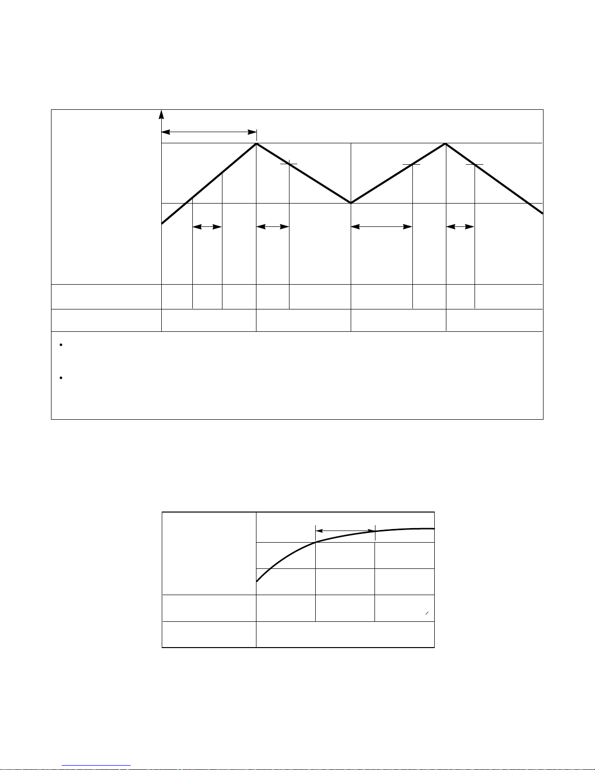
7. Hot-Start Control
• The indoor fan stops until the evaporator piping temperature reaches to 25°C.
• If the evaporator piping temperature drops below 22°C, indoor fan stops again.
• The operation diagram is as follows.
PIPING
TEMPERATURE
1min
COMPRESSOR
INDOOR FAN
ON
OFF LOW
Selected
fan speed
22°C
25°C
–21–
8. Defrost Control
• Defrost control is available 45 minutes later since heating mode operation started, and it will not prolong over
10 minutes.
• Defrost control is carried out when the outdoor pipe temp. falls below -6°C for more than 3 minutes after 45
minutes passed from starting of heating operation.
• Defrost ends after 10 minutes passed from starting of defrost operation or when the outdoor pipe temp. rises
over 12°C after 5 minutes passed from starting of defrost.
9. Self-Diagnosis Function
• 'CH' will flash in the remote controller display when a problem occurs.
• Correct the 'FAULT MESSAGES' as shown in the table below before restarting operation.
• During the normal operation 'CH' won't be displayed in the remote controller.
Remote controller LCD FAULT MESSAGES
CH 01 Indoor temperature thermistor error
CH 02 Indoor piping thermistor error
CH 03 Indoor/Outdoor unit communication error
CH 04 Water level float switch error
More than 45 minutes
of heating operation
Within
9min. 45sec.
ON OFF
ON
ON
ON OFF
COMPRESSOR
4-WAY VALVE
INDOOR FAN
-6°C ON
12°C OFF
The outdoor
piping Temp.
More than 10 min.
running of compressor
More than 45 minutes
of heating operation
HOT-
START
ON
–22–
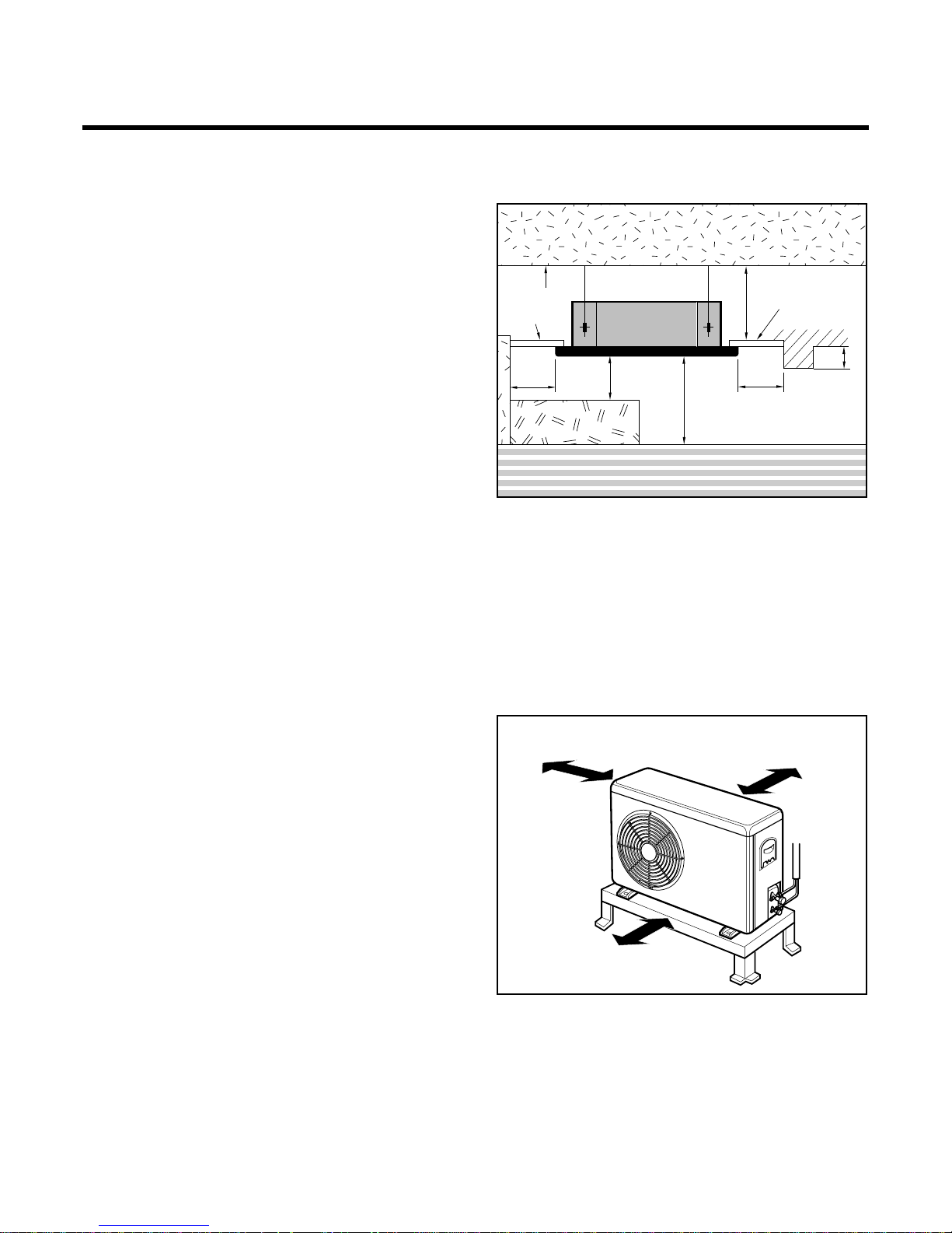
Installation of Indoor, Outdoor Unit
1. Selection of the best location
1) Indoor unit
• There should not be any heat source or steam
near the unit.
• There should not be any obstacles to the air circulation.
• A place where air circulation in the room will be
good.
• A place where drainage can be easily obtained.
• A place where noise prevention is taken into con-
sideration.
• Do not install the unit near the door way.
• Ensure the spaces indicated by arrows from the
wall, ceiling, or other obstacles.
• The indoor unit must have the maintenance
space around.
2) Outdoor unit
• If an awning is built over the unit to prevent direct
sunlight or rain exposure, be careful that heat
radiation from the condenser is not restricted.
• There should not be any animals or plants which
could be affected by hot air discharged.
• Ensure the spaces indicated by arrows from the
wall, ceiling, fence or other obstacles.
More than 10cm
More than 10cm
More than 70cm
Unit:cm
Ceiling
Ceiling Board
Ceiling Board
30 or more
Above 250
300 or less
100
or more
50 or
more
50 or
more
30 or less
Floor
–23–
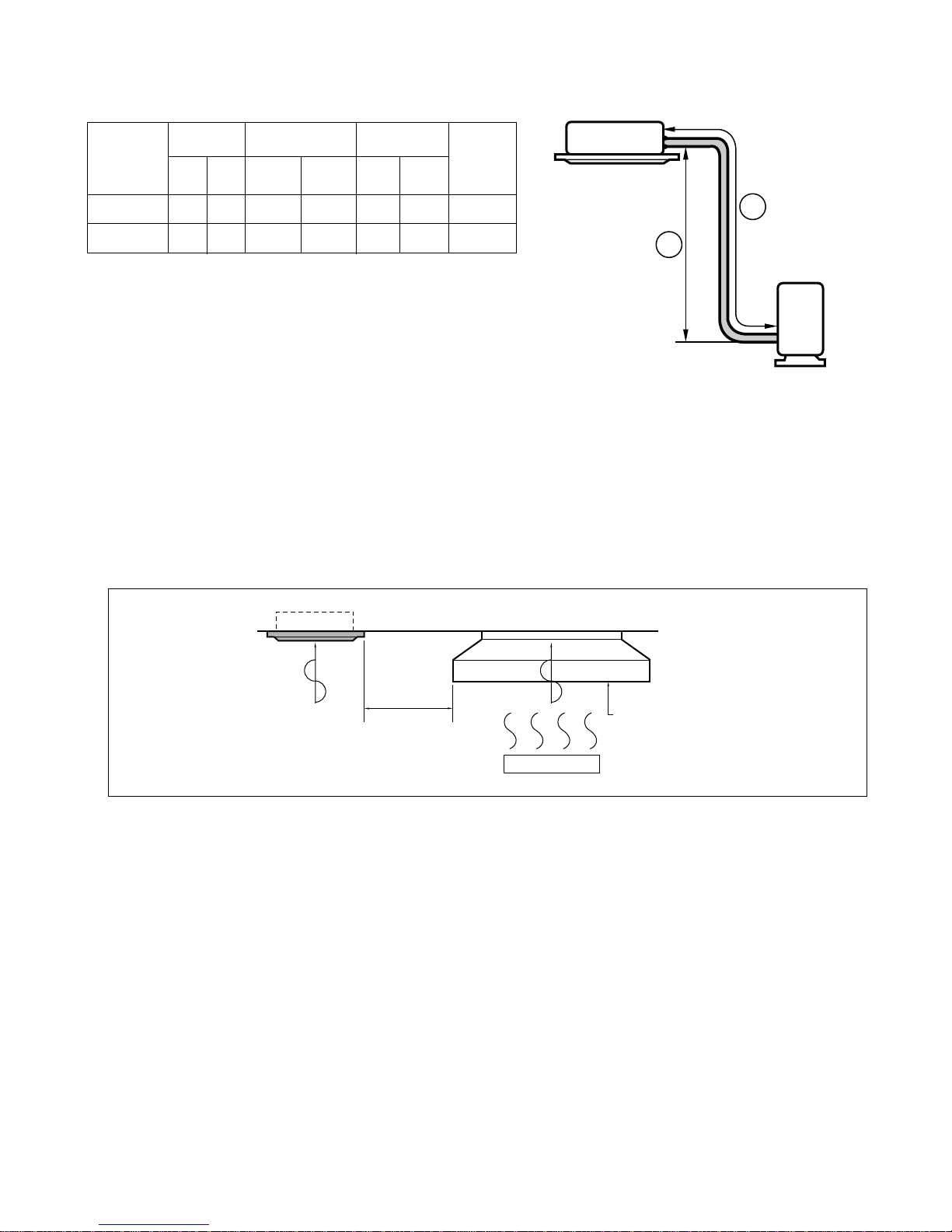
Indoor unit
Outdoor unit
B
A
• Rated performance for refrigerant line length of: 5m
• If 24K or 28K Model is installed at a distance of 15m, 500g of refrigerant
should be added ....................................................(15-5)x50g
3) Piping length and the elevation
MODEL
24K, 28K, 30K BTU
5/8" 3/8" 5 20
36
K BTU
3/4" 3/8" 5 25
GAS LIQUID
515 50
520 70
Elevation B(m)
Length A(m)
* Additional
refrigerant
(g/m)
Pipe Size
Rated Rated
Max. Max.
NOTE:
• Avoid the following installation location.
1. Such places as restaurants and kitchen where considerable amount of oil steam and flour is generated.
These may cause heat exchange efficiency reduction, or water drops, drain pump mal-function.
In these cases, take the following actions;
• Make sure that ventilation fan is enough to cover all noxious gases from this place.
• Ensure enough distance from the cooking room to install the air conditioner in such a place where it may
not suck oily steam.
2. Avoid installng air conditioner in such places where cooking oil or iron powder is generated.
3. Avoid places where inflammable gas is generated.
4. Avoid place where noxious gas is generated.
5. Avoid places near high frequency generators.
Use the ventilation fan
for smoke-collecting
hood with sufficient
capacity.
Cooking table
Air conditioner
Take enough
distance
–24–
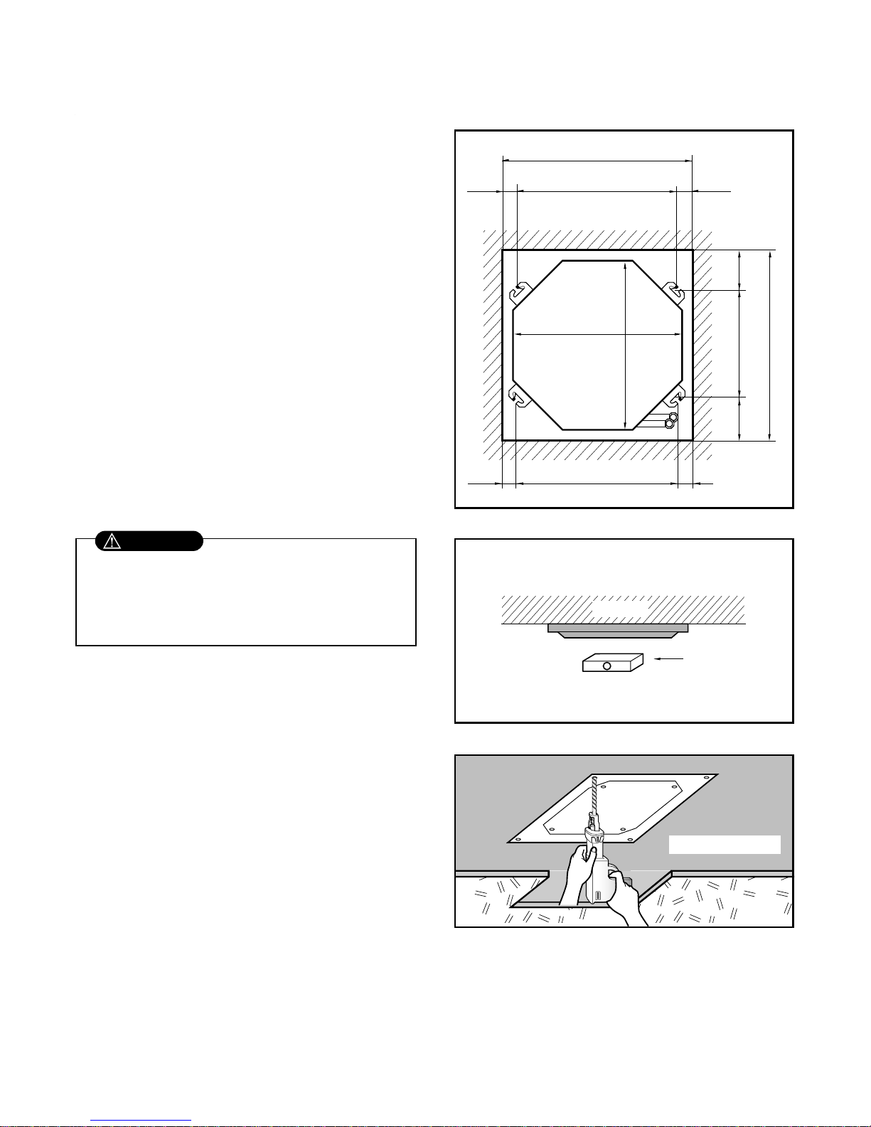
• The dimensions of the paper model for installing are
the same as those of the ceiling opening dimensions.
• Select and mark the position for fixing bolts and piping hole.
• Decide the position for fixing bolts slightly tilted to
the drain direction after considering the direction of
drain hose.
• Drill the hole for anchor bolt on the wall.
Level gauge
Unit:mm
Ceiling
800 Unit size
800 Unit size
720 (Hanging bolt)
6060
840 (Ceiling opening)
840 (Ceiling opening)
624(Hanging bolt)
108
108
600
120
120
Ceiling board
• This air-conditioner uses a drain pump.
• Install the unit horizontly using a level gauge.
• During the installation, care must be taken not to
damage electric wires.
CAUTION
2. Ceiling opening dimensions and hanging bolt location
 Loading...