

Page 1
INSTALLATION
US
TM
INSTRUCTIONS
DIRECT VENT
This appliance may be installed in an aftermarket
permanently located, manufactured home (USA
only) or mobile home, where not prohibited by
local codes. This appliance is only for use with
the type of gas indicated on the rating plate. This
appliance is not convertible for use with other
gases, unless a certified kit is used.
In the Commonwealth of Massachusetts:
• Installation must be performed by a licensed plumber or
gas fitter;
• See Table of Contents for location of additional Commonwealth of Massachusetts requirements.
A French manual is available upon request. Order P/N 850,026CF
Ce manuel d’installation est disponible en francais, simplement
en faire la demande. Numéro de la pièce 850,026CF.
WARNING: IF THE INFORMATION IN THIS MANUAL
IS NOT FOLLOWED EXACTLY, A FIRE OR EXPLOSION MAY RESULT CAUSING PROPERTY DAMAGE,
PERSONAL INJURY OR LOSS OF LIFE.
FOR YOUR SAFETY: Do not store or use gasoline
or other flammables or liquids in the vicinity of
this or any other appliance.
FOR YOUR SAFETY: What to do if you smell gas:
• DO NOT light any appliance.
• DO NOT touch any electrical switches.
• Do not use any phone in your building.
• Immediately call your gas supplier from a
neighbor’s phone. Follow your gas suppliers
instructions.
• If your gas supplier cannot be reached, call
the fire department.
Installation and service must be performed by
a qualified installer, service agency or the gas
supplier.
MONTEBELLO™
VENTED GAS FIREPLACE - DIRECT VENT MODELS
P/N 850,026M REV. D 08/2007
MODELS
Millivolt Models Electronic Models
LSM40MN-2 LSM40EN-2
LSM40MP-2 LSM45EN-2
LSM45MN-2
LSM45MP-2
INSTALLER: Leave this manual with the appliance.
CONSUMER: Retain this manual for future reference.
AVERTISSEMENT: ASSUREZ-VOUS DE BIEN
SUIVRE LES INSTRUCTIONS DONNÉ DANS CETTE
NOTICE POUR RÉDUIRE AU MINIMUM LE RISQUE
D'INCENDIE OU POUR ÉVITER TOUT DOMMAGE
MATÉRIEL, TOUTE BLESSURE OU LA MORT.
POUR VOTRE SÉCURITÉ: Ne pas entreposer ni
utiliser d'essence ni d'autre vapeurs ou liquides
inflammables dans le voisinage de cet appareil ou
de tout autre appareil.
POUR VOTRE SÉCURITÉ: Que faire si vous sentez
une odeur de gaz:
• Ne pas tenter d'allumer d'appareil.
• Ne touchez à aucun interrupteur. Ne pas vous
servir des téléphones se trouvant dans le batiment où vous vous trouvez.
• Evacuez la piéce, le bâtiment ou la zone.
• Appelez immédiatement votre fournisseur de
gaz depuis un voisin. Suivez les instructions du
fournisseur.
• Si vous ne pouvez rejoindre le fournisseur de
gaz, appelez le service dos incendies.
OTL Report No. 116-F-22-5
L'installation et service doit être exécuté par un
qualifié installeur, agence de service ou le fournisseur de gaz.
Page 2
Dr
ywall
T
op Of Firepl
ace
Opening
Non-Combus
tible
TABLE OF CONTENTS
Packaging .........................................Page 2
Introduction ......................................Page 2
General Information ..........................Page 2
New York & Massachusetts
Requirements ................................Page 4
Location ............................................Page 5
Appliance and Vent Clearances ........Page 5
Vent Termination Clearances ............Page 6
Typical Installation Sequence ...........Page 6
Detailed Installation Steps .................Page 6
Step 1. Framing ...............................Page 6
Step 2. Routing Gas Line ................Page 6
Fireplace Specifications .....................Page 8
Step 3. Install the Vent System .......Page 10
Vertical Termination Systems ............Page 10
Vent Section Length Chart ................Page 11
Vertical Vent Tables and Figures ........Page 13
Horizontal Termination System .........Page 15
Horizontal Vent Tables and Figures ...Page 17
Step 4. Field Wiring .........................Page 19
Step 5. Removing Glass Door
Frame Assembly ...........................Page 20
Step 6. Connecting Gas Line ...........Page 20
Step 7. Installing Logs ...................Page 20
Step 8. Checking Appliance
Operation ........................................Page 21
Step 9. Installing Glass Door ..........Page 21
Step 10. Burner Adjustments ............Page 21
Finishing Requirements ....................Page 22
Cold Climate Insulation .....................Page 24
Installation Accessories ....................Page 24
Gas Conversion Kits .................. Page 26
PACKAGING
The assembled vented gas fireplace is packaged with:
1 - one envelope located in the firebox contain
ing the literature package, which consists of
the Care and Operation Manual, Installation
Instructions, Log Placement Guide and
Warranty
2- A bag of glowing embers and Lava Rock
3 - one of the following brick liner kits:
a. Brick Liner Kit, Rustic
b. Brick Liner Kit, Herringbone
c. Brick Liner Kit, Old Cottage
d. Brick Liner Kit, Black.
e. Brick Liner Kit, Red Rustic
f. Brick Liner Kit, Red Herringbone
4 - one of the following log sets:
a. Birch Log set
b. Oak Log set
5 - pull screen
6 - door modesty shield
INTRODUCTION
These vented gas fireplaces are sealed combustion gas fireplaces designed for residential
applications. These appliances must be installed
with the Secure Vent™ vent systems routed to
the outside atmosphere.
Millivolt appliances are designed to operate on
natural or propane gas. A millivolt gas control
valve with piezo ignition system provides safe
and efficient operation.
Electronic appliances are designed to operate
on natural gas or propane. An electronic intermittent pilot ignition system provides safe,
efficient operation. External electrical power is
required to operate these units.
The appliance, when installed, must be electrically grounded in accordance with local codes or,
in the absence of local codes, with the National
Electrical Code, ANSI/NFPA 70, or the Canadian
Electrical Code, CSA C22.1.
-
DO NOT ATTEMPT TO ALTER OR MODIFY
THE CONSTRUCTION OF THE APPLIANCE OR
ITS COMPONENTS. ANY MODIFICATION OR
ALTERATION MAY VOID THE WARRANTY,
CERTIFICATION AND LISTINGS OF THIS
UNIT.
GENERAL INFORMATION
Note: Installation and repair should be performed by a qualified service person. The appliance should be inspected annually by a qualified
professional service technician. More frequent
inspections and cleaning may be required due to
excessive lint from carpeting, bedding material,
etc. It is imperative that the control compartment, burners and circulating air passage ways
of the appliance be kept clean.
S'assurer que le brùleur et le compartiment des
commandes sont propres. Voir les instructions
d'installation et d'utilisation qui accompagnent
l'appareil.
Provide adequate clearances around air openings and adequate accessibility clearance for
service and proper operation. Never obstruct
the front openings of the appliance.
TYPICAL INSTALLATION
This installation manual will help you obtain a
safe, efficient, dependable installation for your
appliance and vent system.
Please read and understand these
instructions before beginning your
installation.
2
These appliances comply with National Safety
Standards and are tested and listed by OMNITest Laboratories (Report No. 116-F-22-5)
to ANSI Z21.50 (in Canada, CSA-2.22), and
CAN/CGA-2.17-M91 in both USA and Canada,
as vented gas fireplace.
Both millivolt and electronic versions of
these appliances are listed by OMNI-Test
Laboratories for installation in bedrooms and
mobile homes.
The Installation must conform to local codes or,
in the absence of local codes, with the National
Fuel Gas Code, ANSI Z223.1/NFPA 54 - latest
edition, or the Natural Gas and Propane Instal-
lation Code, CSA B149.1.
Figure 1
NOTE: DIAGRAMS & ILLUSTRATIONS ARE NOT TO SCALE.
Page 3

These appliances are designed to operate on
natural or propane gas only.
Millivolt Models -
Millivolt models come standard with the manually-modulated gas valve; flame appearance and
heat output can be controlled at the gas valve.
Input of millivolt models is shown in the following table:
Millivolt Models with
Manually-Modulated Gas Valve
Model No. Input (BTU/Hr)
Natural Gas
LSM40MN-2 40,000 to 50,000
LSM45MN-2 47,000 to 60,000
Propane Gas
LSM40MP-2 40,000 to 50,000
LSM45MP-2 48,000 to 60,000
Table 1
Electronic Models -
Electronic models have a manually modulated
gas valve. Input of electronic models is shown
in the following table:
Electronic Models with
Manually-Modulated Gas Valve
Model No. Input
(BTU/Hr)
Natural Gas
LSM40EN-2 40,000 to 50,000
LSM45EN-2 47,000 to 60,000
Propane Gas
LSM40EP-2* 40,000 to 50,000
LSM45EP-2* 48,000 to 60,000
Table 2 * If field converted to propane
All Models -
Maximum manifold pressure is 3.5 in. w.c. (0.87
kPa) for natural gas and 10 in. w.c. (2.49 kPa)
for LP/Propane gas.
Installations at altitudes of 0 to 4500 ft.Units are tested and approved for elevations
of 0 to 4500 feet (0 to 1372 meters).
Installations at altitudes above 4500 ft.For elevations above 4500 feet (1372 meters),
install the unit according to the regulations of
the local authorities having jurisdiction and,
in the USA, the latest edition of the National
Fuel Gas Code (ANSI Z223.1) or, in Canada,
the latest edition of the CAN1-B149.1 and
.2 codes.
Table 3 shows the gas orifice size required
for the elevations indicated.
Model Orifice Size Elevation
Nat. Prop.
LSM40-2 .1405"
(#28)
LSM45-2 .161"
(#20)
Feet (meters)
.086"
(#44) 0-4500
.093"
(0-1372)
(#42)
Table 3
The millivolt appliances are manually controlled
and feature a spark igniter (piezo) that allows the
appliance's pilot gas to be lit without the use of
matches or batteries. This system provides continued service in the event of a power outage.
Do not use these appliances if any part has
been under water. Immediately call a qualified,
professional service technician to inspect the
appliance and to replace any parts of the control
system and any gas control which have been
under water.
Ne pas se servir de cet appareil s'il a été plongé
dans l'eau, complètement ou en partie. Appeler
un technicien qualifié pour inspecter l'appareil et
remplacer toute partie du système de contrôle
et toute commande qui ont été plongés dans
l'eau.
This appliance may be installed in an
aftermarket permanently located, manufactured home (USA only) or mobile home,
where not prohibited by local codes. This
appliance is only for use with the type of
gas indicated on the rating plate. This
appliance is not convertible for use with
other gases, unless a certified kit is used.
Cet appareil peut être installé dans un maison
préfabriquée (É.-U. seulement) ou mobile
déjà installée à demeure si les réglements
locaux le permettent.
Cet appareil doit être utilisé uniquement
avec les types de gaz indiqués sur la plaque
signalétique. Ne pas l'utiliser avec d'autres
gaz sauf si un kit de conversion certifié est
installé.
Test gauge connections are provided on the
front of the millivolt and electronic gas control
valve (identified IN for the inlet and OUT for the
manifold side).
Minimum inlet gas pressure to these appliances
is 5.5 inches water column (1.37 kPa) for natural
gas and 11 inches water column (2.74 kPa) for
propane for the purpose of input adjustment.
Maximum inlet gas supply pressure to these
appliances is 10.5 inches water column (2.61
kPa) for natural gas and 13.0 inches water
column (3.23 kPa) for propane.
These appliances must be isolated from the
gas supply piping system (by closing their
individual manual shut-off valve) during any
pressure testing of the gas supply piping
system at test pressures equal to or less than
1/2 psig (3.5 kPa).
These appliances and their individual shut-off
valves must be disconnected from the gas supply piping system during any pressure testing
of that system at pressures in excess of 1/2
psig (3.5 kPa).
These appliances must not be connected to a
chimney or flue serving a separate solid fuel
burning appliance.
Carbon Monoxide Poisoning: Early signs of
carbon monoxide poisoning are similar to the
flu with headaches, dizziness and/or nausea.
If you have these signs, obtain fresh air immediately. Have the appliance serviced by a
qualified technician as it may not be operating
correctly. Some people are more affected by
carbon monoxide than others. These include
pregnant women, people with heart or lung
disease or anemia, those under the influence
of alcohol, and those at high altitudes.
NOTE: DIAGRAMS & ILLUSTRATIONS ARE NOT TO SCALE.
3
Page 4

New York City, New York (MEA)
Inspection
Installation of these fireplaces are approved for installation in New York
City in the US state of New York.
Requirements for the Commonwealth of Massachusetts
Note: The following requirements reference various Massachusetts
and national codes not contained in this document.
For all side wall horizontally vented gas fueled equipment installed in every
dwelling, building or structure used in whole or in part for residential
purposes, including those owned or operated by the Commonwealth and
where the side wall exhaust vent termination is less than seven (7) feet
above finished grade in the area of the venting, including but not limited
to decks and porches, the following requirements shall be satisfied:
Installation Of Carbon Monoxide Detectors
At the time of installation of the side wall horizontal vented gas fueled
equipment, the installing plumber or gasfitter shall observe that a hard
wired carbon monoxide detector with an alarm and battery back-up is
installed on the floor level where the gas equipment is to be installed.
In addition, the installing plumber or gasfitter shall observe that a battery operated or hard wired carbon monoxide detector with an alarm is
installed on each additional level of the dwelling, building or structure
served by the side wall horizontal vented gas fueled equipment. It shall
be the responsibility of the property owner to secure the services of
qualified licensed professionals for the installation of hard wired carbon
monoxide detectors.
In the event that the side wall horizontally vented gas fueled equipment
is installed in a crawl space or an attic, the hard wired carbon monoxide
detector with alarm and battery back-up may be installed on the next
adjacent floor level.
In the event that the requirements of this subdivision can not be met
at the time of completion of installation, the owner shall have a period
of thirty (30) days to comply with the above requirements; provided,
however, that during said thirty (30) day period, a battery operated carbon
monoxide detector with an alarm shall be installed.
The state or local gas inspector of the side wall horizontally vented gas
fueled equipment shall not approve the installation unless, upon inspection,
the inspector observes carbon monoxide detectors and signage installed
in accordance with the provisions of 248 CMR 5.08(2)(a)1 through 4.
Exemptions
The following equipment is exempt from 248 CMR 5.08(2)(a)1 through 4:
• The equipment listed in Chapter 10 entitled “Equipment Not Required
To Be Vented” in the most current edition of NFPA 54 as adopted by
the Board; and
• Product Approved side wall horizontally vented gas fueled equipment
installed in a room or structure separate from the dwelling, building
or structure used in whole or in part for residential purposes.
MANUFACTURER REQUIREMENTS
Gas Equipment Venting System Provided
When the manufacturer of Product Approved side wall horizontally
vented gas equipment provides a venting system design or venting system components with the equipment, the instructions provided by the
manufacturer for installation of the equipment and the venting system
shall include:
• Detailed instructions for the installation of the venting system design
or the venting system components; and
• A complete parts list for the venting system design or venting sys
tem.
Gas Equipment Venting System NOT Provided
When the manufacturer of a Product Approved side wall horizontally
vented gas fueled equipment does not provide the parts for venting the
flue gases, but identifies “special venting systems”, the following require-
ments shall be satisfied by the manufacturer:
• The referenced “special venting system” instructions shall be included
with the appliance or equipment installation instructions; and
-
Approved Carbon Monoxide Detectors
Each carbon monoxide detector as required in accordance with the
above provisions shall comply with NFPA 720 and be ANSI/UL 2034
listed and IAS certified.
Signage
A metal or plastic identification plate shall be permanently mounted to
the exterior of the building at a minimum height of eight (8) feet above
grade directly in line with the exhaust vent terminal for the horizontally
vented gas fueled heating appliance or equipment. The sign shall read, in
print size no less than one-half (1/2) inch in size, “GAS VENT DIRECTLY
BELOW. KEEP CLEAR OF ALL OBSTRUCTIONS.”
4
NOTE: DIAGRAMS & ILLUSTRATIONS ARE NOT TO SCALE.
• The “special venting systems” shall be Product Approved by the
Board, and the instructions for that system shall include a parts list
and detailed installation instructions.
A copy of all installation instructions for all Product Approved side wall
horizontally vented gas fueled equipment, all venting instructions, all
parts lists for venting instructions, and/or all venting design instructions
shall remain with the appliance or equipment at the completion of the
installation.
• Installation and repair must be done by a plumber or gas fitter licensed
in the Commonwealth of Massachusetts.
• The flexible gas line connector used shall not exceed 36 inches (92
centimeters) in length.
• The individual manual shut-off must be a T-handle type valve.
Page 5
HORIZONTAL VENT
VERTICAL VENT
CROSS CORNER
APPLICA
TION
RECESSED
APPLICATION
FLA
T
APPLICA
TION
ROOM DIVIDER
APPLICA
TION
FLA
T ON W
ALL
APPLICA
TION
ISLAND
APPLICA
TION
Shelf Height
(
see table)
Do not insulate the
space between the
appliance and the
area above it.
Shelf Above Fireplace With Top Venting
2 Foot
Vertical
Vent
(Min.)
Failure to comply with the installation and operating instructions
provided in this document will
result in an improperly installed
and operating appliance, voiding
its warranty. Any change to this
appliance and/or its operating
controls is dangerous. Improper
installation or use of this appliance can cause serious injury or
death from fire, burns, explosion
or carbon monoxide poisoning.
Children and adults should be
alerted to the hazards of high
surface temperatures. Use
caution around the appliance
to avoid burns or clothing ignition. Young children should be
carefully supervised when they
are in the same room as the
appliance.
Note: An Optional Screen Door
or Screen Panel for the glass is
available (see Care and Operations Manual for ordering information).
Do not place clothing or other
flammable materials on or near
this appliance.
Surveiller les enfants. Garder les
vêtements, les meubles, l'essence
ou autres liquides à vapeur inflammables lin de l'appareil.
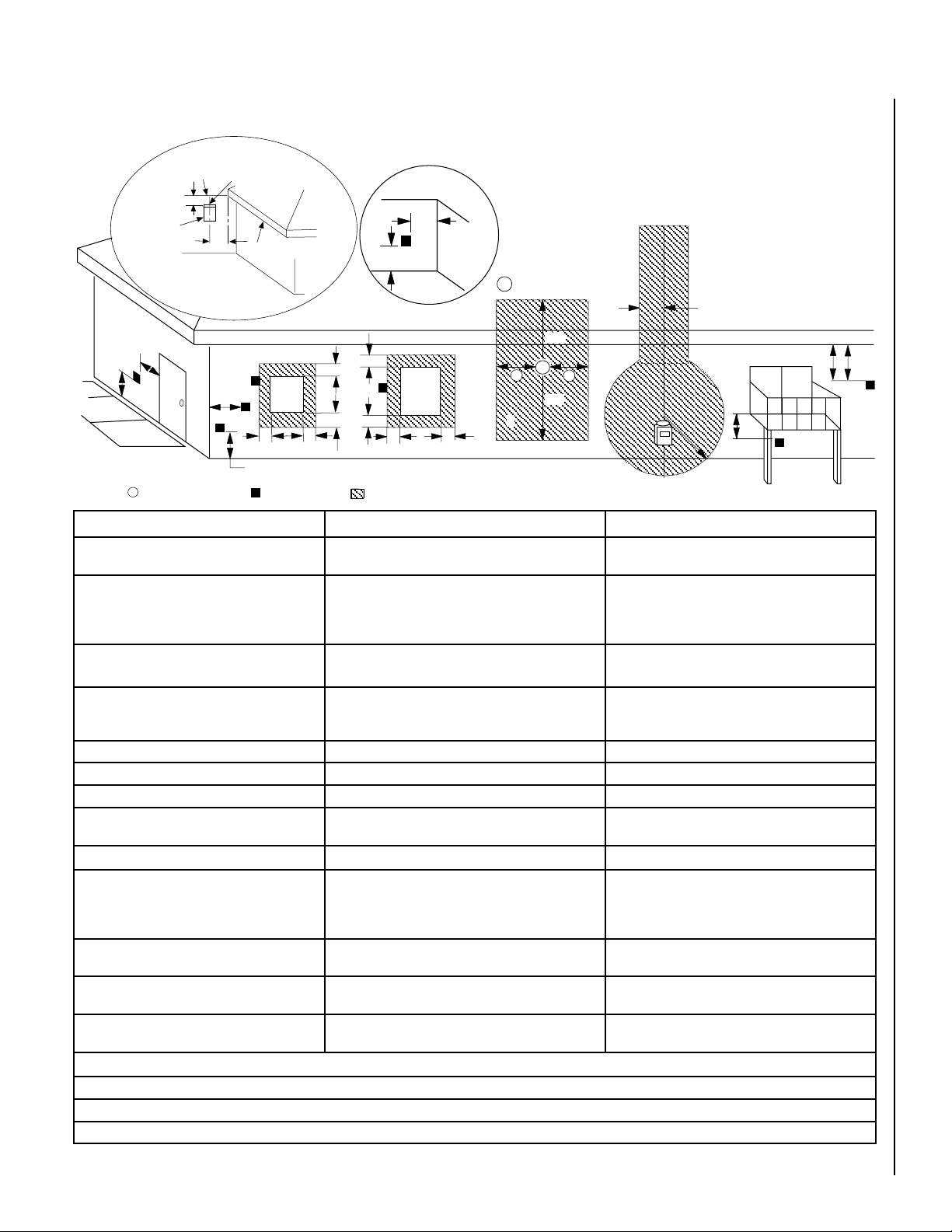
LOCATION
In selecting the location, the aesthetic and functional use of the appliance are primary concerns.
However, vent system routing to the exterior and
access to the fuel supply are also important.
Consideration should be given to traffic ways,
furniture, draperies, etc., due to elevated surface
temperatures (Figure 2). The location should
also be free of electrical, plumbing or other
heating/air conditioning ducting.
WARNING
WARNING
WARNING
AVERTISSEMENT
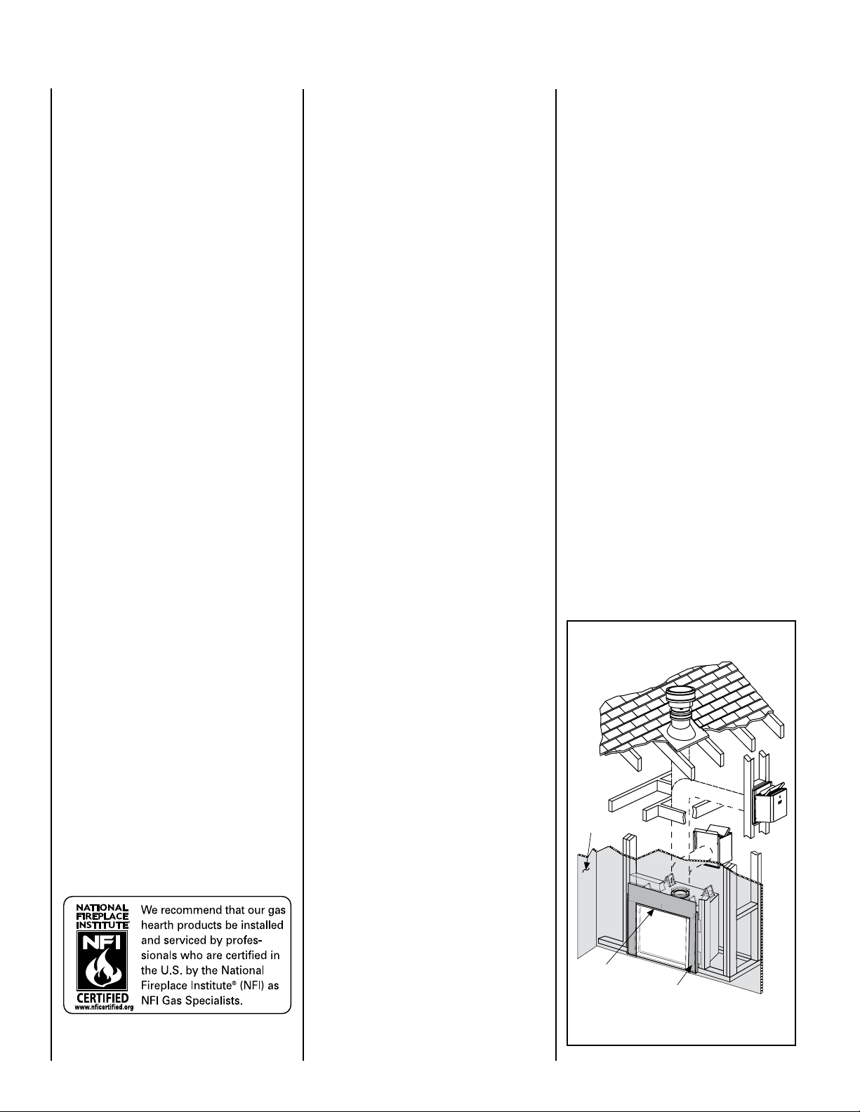
Do not insulate the space between the appliance and the area above it. See Figure 3. The
minimum height from the base of the appliance
to the underside of combustible materials used
to construct a utility shelf in this fashion is
shown in the table in Figure 3.
*Note: See Page 6, Step 1 for clearance
requirements to the nailing flange located at
each side of the unit and any screw heads
adjacent to it.
Figure 2
MINIMUM VENTING CLEARANCES
Inches (millimeters)
Vertical Sections
Sides 1" (25 mm)
Horizontal Sections
Top 3" (75 mm)
Bottom 1" (25 mm)
Sides 1" (25 mm)
Vertical Vent Applications
Sides 1" (25 mm)
Table 4
APPLIANCE MINIMUM CLEARANCES*
Bottom of Appliance
Inches (millimeters)
Back 1/2 (13)
0 (0) Spacers
Sides 1/2 (13)
0 (0) Spacers
Top Spacers 0 (0)
Floor 0 (0)
To Ceiling
69 (1743)
Table 5
NOTE: DIAGRAMS & ILLUSTRATIONS ARE NOT TO SCALE.
Typical Locations
The appliance should be mounted on a fully
supported base extending the full width and
depth of the unit. The appliance may be located
on or near conventional construction materials.
However, if installed on combustible materials,
such as carpeting, vinyl tile, etc., a metal or
wood barrier covering the entire bottom surface
must be used.
APPLIANCE AND VENT CLEARANCES
The appliance is approved with zero clearance to
combustible materials on all sides (as detailed
in Table 5), with the following exception: When
the unit is installed with one side flush with a
wall, the wall on the other side of the unit must
not extend beyond the front edge of the unit. In
addition, when the unit is recessed, the side walls
surrounding the unit must not extend beyond
the front edge of the unit. See Figure 2.
Combustible Shelf Height
Model No.
LSM40-2 *84-1/16 (2135)
LSM45-2 89-1/16 (2252)
* Includes 3” clearance to combustibles
(required above vent components)
Inches (millimeters)
Top Vent - with 2 Feet Vertical Vent
and One 90 Degree Elbow
Secure Vent
Figure 3
5
Page 6
Right Side
Front Corner
Of Fireplace
Framing
6-1/4”
(159 mm
)
19-5/8”
(498 mm
)
3"
(76 mm)
Termination Kit
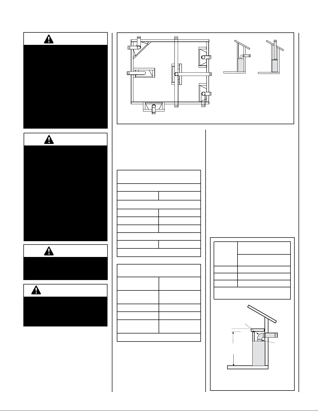
Combustible Projection
greater than 2-1/2 inches in length
Horizontal Vent Termination Clearances
Combustible Projection
2-1/2 inches or less in length
24"
(610 mm)
Ventilated Or
Unventilated Soffit
Note: The nailing flanges
, combustible members
and screw heads locat
ed in areas directly ad
jacent
to the
nailing flanges, are
EXEMPT from the 1/2”
clearance to combustible requirements for th
e
firebox outer wra
pper
. Combustible framing
may be
in
direct contact with
t
he nailing flanges and
m
ay
be loca
ted closer than 1/2” fr
om screw heads and
the firebox
wrapper in areas adjace
nt to the nailing
flanges. Frame th
e
opening to the exact dimens
ions
specified in the framing det
ails of this manual.
Use T
op Flange For
1/2” Thick Dr
ywal
l
Use Bottom Flange Fo
r
5/8” Thick Dr
ywal
l
Front Of
Fireplace
Use Center Flange
For Flush Mount
Left Side Front Co
rner of Fireplace Shown
(R
ight Side Requirements the
S
ame)
Unit Being Secured By Its Nailing Flanges
To The Framing
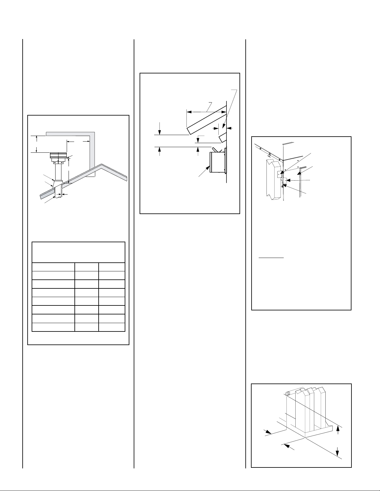
VENT TERMINATION CLEARANCES
12
X
Roof Pitch is X/12
2 FT
MIN.
2 FT MIN.
Lowest
Discharge
Opening
H*
*H = MINIMUM HEIGHT FROM ROOF TO
LOWEST DISCHARGE OPENING OF VENT
TERMINATION HEIGHTS FOR VENTS ABOVE
FLAT OR SLOPED ROOFS
Horizontal Overhang
Vertical
Wall
Vent
Termination
Storm Collar
Concentric
Vent Pipe
Flashing
1 inch (25.4 mm) Minimum
Clearance to Combustibles
These instructions should be used as a guideline and do not supersede local codes in any
way. Install vent according to local codes,
these instructions, the current National Fuel
Gas Code (ANSI-Z223.1) in the USA or the
current standards of CAN/CGA-B149.1 and
-B149.2 in Canada.
Vertical Vent Termination Clearances
Terminate single vent caps relative to building
components according to Figure 4.
Step 1. (Page 6) Construct the appliance framing. Position the appliance within the framing
and secure with nailing brackets.
Step 2. (Page 6) Route gas supply line to the
right side of the appliance.
See Figure 27 on Page 16 for the recess allowances, into
exterior walls, of the square horizontal terminations.
Figure 5 - Side Elevation View
the appliance is to be elevated above floor
level, a solid continuous platform must be
constructed.
Headers may be in direct contact with the
appliance top spacers but must not be supported by them or notched to fit around them.
All construction above the appliance must be
self supporting, DO NOT use the appliance for
structural support.
The fireplace should be secured to the side
framing members using the unit's nailing
flanges - one top and bottom on each side of
the fireplace front. See Figure 6. Use 8d nails
or their equivalent.
The vent / air intake termination clearances
above the high side of an angled roof is as
shown in the following chart:
Termination Heights For Vents
Above Flat Or Sloped Roofs
Ref. NFPA 54 / ANSI Z223.1, 7.6
Roof Pitch * Feet * Meters
Flat to 6/12 1.0 0.3
6/12 to 7/12 1.25 0.38
7/12 to 8/12 1.5 0.46
8/12 to 9/12 2.0 0.61
9/12 to 10/12 2.5 0.76
10/12 to 11/12 3.25 0.99
11/12 to 12/12 4.0 1.22
Figure 4
Terminate multiple vent terminations according to the installation codes listed at the top
of this Page.
Horizontal Vent Termination Clearances
The horizontal vent termination must have
a minimum of 3" (76 mm) clearance to any
overhead combustible projection of 2-1/2" (64
6
mm) or less. See Figure 5. For projections
exceeding 2-1/2" (64 mm), see Figure 5. For
additional vent location restrictions refer to
Figure 8 on Page 7.
TYPICAL INSTALLATION SEQUENCE
The typical sequence of installation follows,
however, each installation is unique resulting
in variations to those described.
See the Page numbers references in the following steps for detailed procedures.
(Page 10) Install the vent system and
Step 3.
exterior termination.
Step 4. (Page 19) Field Wiring
a. Millivolt and Electronic Appliances – The
operating control switch is factory installed.
b. Electronic Appliances – Connect 120 Vac
electrical power to the appliance receptacle.
Step 5. (Page 20) Remove glass door frame
assembly.
Step 6. (Page 20) Make connection to gas
supply.
Step 7. (Page 20) Install ceramic panels, logs
and glowing embers.
Step 8. (Page 21) Checkout appliance opera-
Unit Being Secured by Its Nailing
Flanges to the Framing
Figure 6
tion.
Step 9. (Page 21) Install glass door frame
assembly.
Step 10. (Page 21) Adjust burner to ensure
proper flame appearance.
Step 2. ROUTING GAS LINE
Route a 1/2" (13 mm) gas line along the inside
of the right side framing as shown in Figure
7. Gas lines must be routed, constructed and
DETAILED INSTALLATION STEPS
The appliance is shipped with all gas controls
and components installed and pre-wired.
Remove the shipping carton, exposing the
front glass door. Using a Phillips screwdriver,
made of materials that are in strict accordance
with local codes and regulations.
All appliances are factory-equipped with a
flexible gas line connector and 1/2 inch shutoff
valve. (See Step 5 on Page 20).
unfasten two (2) screws located at the top of the
glass frame (see Figure 37). Tilt the top of the
glass frame away from the unit. Lift it carefully
off the bottom door track and set the door aside,
protecting it from inadvertent damage.
Step 1. FRAMING
Frame these appliances as illustrated in Figure
9 on Page 8, unless the appliance is to be
installed in a corner. See Figure 10 on Page
8 for corner framing installations. All framing
details must allow for a minimum clearance to
combustible framing members as shown in
Table 5 on Page 5.
Figure 7
Page 7
EXTERIOR HORIZONTAL VENT TERMINATION CLEARANCE REQUIREMENTS
V
V
V
V
V
F
C
B
B
A
B
H
M
I
X
V
D
V
A
A
A
V
L
B
J
X
E
V
A
G
*18”
18”
B
C
C
C
* See Item D in the Text Below.
Exterior Wall
24"
Horizontal
Termination
Inside Corner
= Air Supply Inlet
Center Line
of Termination
36"
DETAIL D
Ventilated Soffit
Fixed
Closed
Window
= Vent Terminal
Inside
Corner Detail
= 9" in U.S.
= 12" in Canada
Operable
Window
= Area where Terminal is NOT permitted
3 ft.
3 ft.
Minimum Clearances Canadian Installation * US Installation **
A = Clearance above grade, veranda, porch, deck
or balcony.
B = Clearance to window or door that may be
opened.
C = Clearance to permanently closed window 12 inches (305 mm) to prevent window condensation 9 inches (229 mm) recommended to prevent window
12 inches (30 cm) * 12 inches (30 cm) **
6 in. (15.2 cm) for appliances < 10,000 BTU/hr (3kW),
12 in. (30 cm) for appliances > 10,000 BTU/hr (3kW) and <
100,000 BTU/hr (30kW), 36 inches (91 cm) for appliances
> 100,000 BTU/hr (30kW)*
6 in. (15.2 cm) for appliances < 10,000 BTU/hr (3kW),
9 in. (23 cm) for appliances > 10,000 BTU/hr (3kW) and <
50,000 BTU/hr (15kW), 12 inches (30 cm) for appliances
> 50,000 BTU/hr (15kW)*
condensation
D = Vertical clearance to ventilated soffit located
24 inches (61.0 cm) 24 inches (61.0 cm)
above the terminal within a horizontal distance of 36
in. (91.4cm) from the center line of the terminal
E = Clearance to unventilated soffit 24 inches (61.0 cm) 24 inches (61.0 cm)
F = Clearance to outside corner 5 inches (12.7 cm) 5 inches (12.7 cm)
G = Clearance to inside corner 36" (91.4 cm) 24 inches (61.0 cm)
H = Clearance to each inside of center line extended
above meter / regulator assembly
3 feet (91 cm) within a height of 15 feet above the meter /
regulator assembly *
3 feet (91 cm) within a height of 15 feet above the meter
/ regulator assembly **
I = Clearance to service regulator vent outlet 3 feet (91 cm) * 3 feet (91 cm) **
J = Clearance to non-mechanical air supply inlet
to building or the combustion air inlet to any other
appliance
K = Clearance to mechanical air supply inlet 6 feet (1.83 meters) * 3 feet (91 cm) above, if within 10 feet (3 m) horizon-
L = Clearance above paved sidewalk or paved
driveway located on public property
M = Clearance under veranda, porch, deck or
balcony
6 in. (15.2 cm) for appliances < 10,000 BTU/hr (3kW), 12
in. (30 cm) for appliances > 10,000 BTU/hr (3kW) and <
100,000 BTU/hr (30kW), 36 inches (91 cm) for appliances
> 100,000 BTU/hr (30kW)*
6 in. (15.2 cm) for appliances < 10,000 BTU/hr (3kW), 9
in. (23 cm) for appliances > 10,000 BTU/hr (3kW) and <
50,000 BTU/hr (15kW), 12 inches (30 cm) for appliances
> 50,000 BTU/hr (15kW)*
7 feet (2.13 m) ‡ 7 feet (2.13 m) ‡
18 in. (46.0 cm) * ‡ 18 in. (46.0 cm) ** ‡
tally**
* In accordance with the current CSA-B149.1 National Gas and B149.2 Propane Installation Code - Latest Editions.
** In accordance with the current ANSI Z223.1 / NFPA 54 National Fuel Codes - Latest Edition.
‡ A vent shall not terminate directly above a sidewalk or paved driveway which is located between two single family dwellings and serves both dwellings.
*‡ Only permitted if veranda, porch, deck or balcony is fully open on a minimum 2 sides beneath the floor.
Figure 8
NOTE: DIAGRAMS & ILLUSTRATIONS ARE NOT TO SCALE.
7
Page 8
C
Back wall of chase/enclosure
(including any finishing materials)
D
A
B
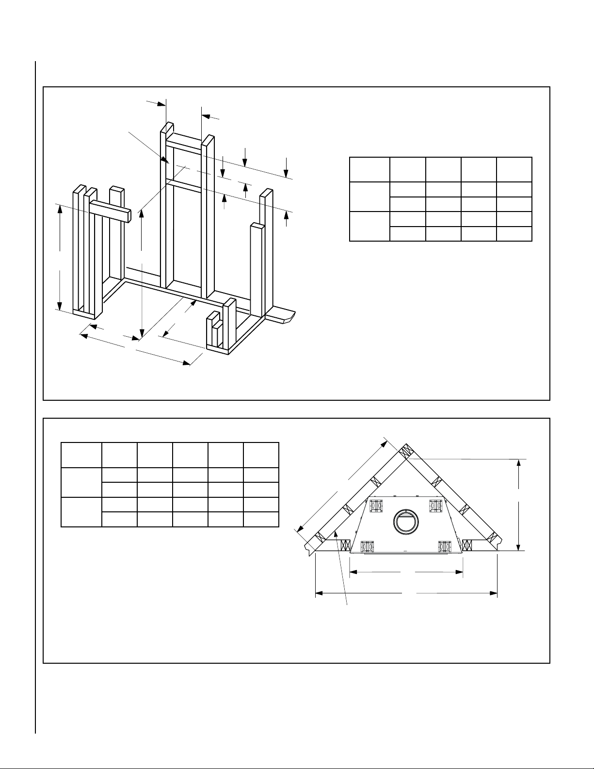
FIREPLACE FRAMING SPECIFICATIONS
A
B
C
8-1/2
(216)
13
(
330
)
VENT FRAMING
-
TOP VENT WITH 2 FEET
VERTICAL VENT AND
ONE 90° ELBOW
Framing should be constructed
of 2x4 or larger lumber.
Inches (mm)
(641)
25-1/4
15
(
381
)
6-1/2
(165)
1/2 A
Figure 9 Framing
Model
No.
LSM40-2
LSM45-2
A B C
in. 50-3/4 43 75-1/8
mm 1289 1092 1908
in. 56-7/8 48 80-1/16
mm 1445 1219 2034
Model
No.
LSM40-2
LSM45-2
Figure 10
8
A B C D
in. 50-5/8 83-5/8 59-1/8 41-7/8
mm 1286 2124 1502 1064
in. 56-3/4 89-7/8 63-1/2 44-7/8
mm 1441 2283 1613 1140
Corner Framing with Square Termination (SV8HTS)
NOTE: DIAGRAMS & ILLUSTRATIONS ARE NOT TO SCALE.
Page 9
E
A
B
D
Top View
Front View
5-3/32 (129)
Right Side View
14-1/8
8-1/2”
(216)
5-1/4”
(133)
(359)
26-15/32
(672)
C
25-29/32
(658)
25-1/2
(648)
7
2-1/2 (64)
(178)
19-5/8
(498)
Gas Inlet
(This
Side
Only)
Electrical
Inlet
8-3/8
(213)
F
G
H
J
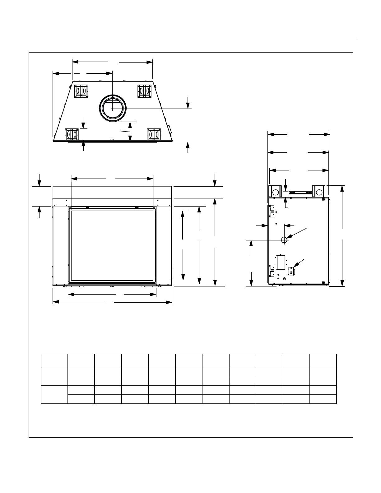
FIREPLACE SPECIFICATIONS
Model
No.
LSM40-2
LSM45-2
Figure 11
Unit Dimensions
A B C D E F G H J
in. 50-5/8 37-1/4 42-7/8 25-5/16 34 37-5/8 33-3/32 29-9/32 34-3/4
mm 1286 946 1089 643 864 956 840 744 883
in. 56-11/16 42-1/4 47-7/8 28-3/8 40-1/8 43-5/8 38-3/32 34-1/2 40-59/64
mm 1440 1073 1216 721 1019 1108 968 876 1039
NOTE: DIAGRAMS & ILLUSTRATIONS ARE NOT TO SCALE.
9
Page 10

T
ermination
Flashing An
d
Storm Collar
Fires
top/Spacer
SV
8
6/12/24/36/48
V
ent Section
s
40' Ma
x
(12.2 M)
6' Mi
n
(1.8 M)
1" (25 mm
)
Minimum
Clearance to
Combustibles
AIR INLET BAFFLE
GRATE
VENT RESTRICTOR INSTALLATION
RESTRICTOR
APPLIANCE VENT OUTLET
Install the restrictor as shown from
inside the unit, in the inner fireplace collar.
When vertically terminating the vent system above
the roof, install a vent restrictor in the top vent of
the fireplace outlet.
Step 3. INSTALL THE VENT SYSTEM
General Information
These instructions should be used as a guideline and do not supersede local codes in any
way. Install vent according to local codes,
these instructions, the current National Fuel
Gas Code (ANSI-Z223.1) in the USA or the
current standards of CAN/CGA-B149.1 and
-B149.2 in Canada.
These fireplaces are designed, tested and
listed for operation and installation with,
and only with, Secure Vent™ (SV8) Direct
Vent System Components, manufactured
by Security Chimneys International.
These approved vent system components
are labeled for identification. DO NOT
use any other manufacturer's vent components with these appliances.
These fireplaces must be vented directly
to the outside.
The vent system may not service multiple
appliances, and must never be connected to a
flue serving a solid fuel burning appliance. The
vent pipe is tested to be run inside an enclosing
wall (such as a chase). There is no requirement
for inspection openings in the enclosing wall at
any of the joints in the vent pipe.
The vertical vent system terminates through
the roof. The minimum vent height above the
roof and/or adjacent walls is specified in ANSI
Z223.1-(latest edition) (In Canada, the current
CAN-1 B149 installation code) by major building codes. Always consult your local codes
for specific requirements. A general guide to
follow is the Gas Vent Rule (refer to Figure 4
on Page 6).
For vertical venting from 6 feet to 12 feet or
more, from the top of the fireplace to the top
of the termination, the installation of a vent
restrictor is required.
Install a vent restrictor (provided) in the appliance flue outlet as shown in Figure 12A. It is
held in place by friction, only.
Vertical (Straight) Installation
(Figure 13)
Determine the number of straight vent sections
required. 4-1/2" (114 mm), 10-1/2" (267 mm),
22-1/2" (572 mm), 34-1/2" (876 mm) and 461/2" (1181 mm) net section lengths are available.
Refer to the Vent Section Length Chart.
Select Venting System - Horizontal or Vertical
With the appliance secured in framing, determine vent routing and identify the exterior
termination location. The following sections
describe vertical (roof) and horizontal (exterior wall) vent applications. Refer to the
section relating to your installation. A list of
approved venting components is shown on
Pages 24 and 25.
VERTICAL TERMINATION SYSTEMS (ROOF)
Figures 12A, 12B on Page 10 and Figures 22
through 24 on Pages 13 and 14 and their asso-
ciated Vertical Vent Tables illustrate the various
vertical venting configurations that are possible
for use with these appliances. A Vertical Vent
Table summarizes each system’s minimum and
maximum vertical and horizontal length values
that can be used to design and install the vent
components in a variety of applications.
Figure 12A
For vertical venting above 12 feet, in addition
to the restrictor (Figure 12A) an air inlet baffle
has to be installed over the grate as shown
in Figure 12B.
Figure 12B
Figure 13
10
NOTE: DIAGRAMS & ILLUSTRATIONS ARE NOT TO SCALE.
Page 11

TRAHCHTGNELNOITCESTNEV
lanimoN
htgneLnoitceS
)sehcni(
6 21 42 63 84
T
O
T
A
L
Q
T
Y
noitceSteN
)sehcni(htgneL
2/1-4 2/1-01 2/1-22 2/1-43 2/1-64
tneVfothgieH snoitceStneVforebmuN
sehcni tf
5.4 573.0 1 0 0 0 0 1
9 57.0 2 0 0 0 0 2
5.01 578.0 0 1 0 0 0 1
51 52.1 1 1 0 0 0 2
5.91 526.1 2 1 0 0
0
3
12 57.1 0 2 0 0 0 2
5.22 578.1 0 0 1 0 0 1
5.52 521.2 1 2 0 0 0 3
5.13 526.2 0 3 0 0 0 3
5.43 578.2 0 0 0 1 0 1
5.73 521.3 1 1 1 0 0 3
5.34 526.3 0 2 1 0 0 3
54 57.3 0 0 2 0 0 2
5.64 578.3 0 0 0 0 1 1
5.94 521.4 1 0 2 0 0 3
15 52.4 1 0 0 0 1 2
5.55 526.4 0 1 2 0 0 3
75 57.4 0 0 1 1 0 2
66 52.5 0 2 2 0 0 4
5.76 526.5 0 0 3 0 0 3
96 57.5 0 0 0 2 0 2
27 6 1 0 3 0 0 4
5.37 521.6 1 0 0 2 0 3
5.97 526.6 0 1 0 2 0 3
18 57.6 0 0 0 1 1 2
09 5.7 0 2 1 0 1 4
5.19 526.7 0 0 2 0 1 3
39 57.7 0 0 0 0 2 2
69 8 1 0 1 2 0 4
5.79 521.8 1 0 0 0 2 3
201 5.8 2 0 0 0 2 4
5.301 526.8 0 0 0 3 0 3
801 9 1 0 0 3 0 4
411 5.9 0 2 0 0 2 4
711 57.9 1 0 5 0 0 6
5.811 578.9 1 1 0 3 0 5
621 5.01 0 0 1 3 0 4
5.031 578.01 1 0 1 3 0 5
531 52.11 0 0 6 0 0 6
831 5.11 0 0 0 4 0 4
5.931 526.11 0 0 0 0 3 3
5.241 578.11 1 0 0 4 0 5
TRAHCHTGNELNOITCESTNEV
noitceSlanimoN
)sehcni(htgneL
6 21 42 63 84
T
O
T
A
L
Q
T
Y
noitceSteN
)sehcni(htgneL
2/1-4 2/1-01 2/1-22 2/1-43 2/1-64
tneVfothgieH snoitceStneVforebmuN
sehcni tf
441 21 1 0 0 0 3 4
051 5.21 0 1 0 0 3 4
5.451 578.21 1 1 0 0 3 5
5.061 573.31 0 2 0 0 3 5
5.271 573.41 0 0 0 5 0 5
771 57.41 1 0 0 5 0 6
381 52.51 0 1 0 5 0 6
681 5.51 0 0 0 0 4 4
5.091 578.51 1 0 0 0 4 5
5.691 573.61 0 1 0 0 4 5
5.502 521.71 0 1 1 5 0 7
702 52.71 0 0 0 6 0 6
5.112 526.71 1 0 0 6 0 7
5.712 521.81 0 1 0 6 0 7
5.922 521.91 0 0 1 6 0 7
5.232 573.91 0 0 0 0 5 5
732 57.91 1 0 0 0 5 6
5.142 521.02 0 0 0 7 0 7
642 5.02 1 0 0 7 0 8
252 12 0 1 0 7 0 8
462 22 0 0 1 7 0 8
672 32 0 0 0 8 0 8
972 52.32 0 0 0 0 6 6
5.082 573.32 1 0 0 8 0 9
5.382 526.32 1 0 0 0 6 7
5.982 521.42 0 1 0 0 6 7
5.103 521.52 0 0 1 0 6 7
5.013 578.52 0 0 0 9 0 9
513 5.62 1 0 0 9 0 01
5.523 521.72 0 0 0 0 7 7
033 5.72 1 0 0 0 7 8
633 82 0 1 0 0 7 8
543 57.82 0 0 0 01 0 01
5.943 521.92 1 0 0 01 0 11
273 13 0 0 0 0 8 8
5.673 573.13 1 0 0 0 8 9
5.973 526.13 0 0 0 11 0 11
5.814 578.43 0 0 0 0 9 9
324 52.53 1 0 0 0 9 01
564 57.83 0 0 0 0 01 01
13” Min.
(330 mm)
13” Min.
(330 mm)
Vertical (Offset) Installation
Analyze the vent routing and determine the
quantities of vent sections and number of elbows
required. Refer to Vertical Vent Figures and
Tables on Pages 13 and 14 to select the type
of vertical installation desired. Vent sections
are available in net lengths of 4-1/2" (114 mm),
10-1/2" (267 mm), 22-1/2" (572 mm), 34-1/2"
(876 mm) and 46-1/2" (1181 mm). Refer to the
Vent Section Length Chart on this Page for an
aid in selecting length combinations. Elbows are
available in 90° and 45° configurations. Refer to
Figure 17 on Page 12 for the SV8 E45 and SV8
E90 elbow dimensional specifications.
Where required, a telescopic vent section
(SV8LA) may be used to provide the installer
with an option in installing in tight and confined spaces or where the vent run made up
of fixed length pieces develops a joint in a
undesirable location, or will not build up to the
required length. The SV8LA Telescopic Vent
Section has an effective length of from 1-1/2"
(38 mm) to 6-3/4" (171 mm). The SV8LA is
fitted with a dimpled end (identical to a normal
vent section component) and a plain end with
3 pilot holes. Slip the dimpled end over the
locking channel end of a standard SV8 vent
component the required distance and secure
with three screws.
Maintain a minimum 1" (25 mm) clearance
to combustible materials for all vertical elements. Clearances for all horizontal elements
are 3" (76 mm) on top, 1" (25 mm) on sides
and 1" (25 mm) on the bottom.
A. Frame ceiling opening - Use a plumb line
from the ceiling above the appliance to locate
center of the vertical run. Cut and/or frame
an opening, 13" x 13" (330 mm x 330 mm)
inside dimensions, about this center mark
(Figure 14).
Figure 14
NOTE: DIAGRAMS & ILLUSTRATIONS ARE NOT TO SCALE.
11
Page 12

First Vent
Component
Align the dimple (four places)
with the opening of the locking
incline channel on appliance
collar. Twist vent component
clockwise to engage and seal.
Locking
Incline Channel
Dimple
Appliance collar
Vent / Appliance Collar
Connection
Align the dimple (four places) of the
upper vent section with the opening of
the locking incline channel on the
lower vent section. Twist vent
component clockwise to engage and
seal until arrow and dimple align.
Locking
Incline Channel
Dimple
Arrow
Connected
Vent Sections
Vent / Vent Section
Connection
Arrow
Arrow
SV8E90
(90 Elbow)
10"
(254 mm)
Swivel Joint
6"
(153 mm)
SV8 E45
(45 Elbo w)
Swivel Joint
(360° swivel)
(360° swivel)
B. Attach vent components to appliance
- Secure Vent SV8 direct vent system compo-
nents are unitized concentric pipe components
featuring positive twist lock connections (see
Figure 15).
All of the appliances covered in this document
are fitted with collars having locking inclined
channels. The dimpled end of the vent components fit over the appliance collar to create
the positive twist lock connection.
Figure 15
Figure 16
C. Attach vent components to each other
- Other vent sections may be added to the
previously installed section in accordance with
the requirements of the vertical vent figures
and tables. To add another vent component
to a length of vent run, align the dimpled end
over the inclined channel end of the previously
installed section, adjusting the radial alignment
until the four locking dimples are aligned with
the inlets of the four incline channels of the
previous section.
Push the vent component against the previous
section until it fully engages, then twist the
component clockwise running the dimples down
and along the incline channels until they seat at
the end of the channels. This seating position
is indicated by the alignment of the arrow and
dimple as shown in Figure 16.
D. Install firestop/spacer at ceiling - When
using Secure Vent, use SV8BF firestop/spacer
at ceiling joists. If there is living space above
the ceiling level, the firestop/spacer must be
installed on the bottom side of the ceiling. If attic
space is above the ceiling, the firestop/spacer
must be installed on the top side of the joist.
Route the vent sections through the framed
opening and secure the firestop/spacer with
8d nails or other appropriate fasteners at each
corner. Remember to maintain 1" (25 mm)
clearance to combustibles, framing members,
and attic or ceiling insulation when running
vertical chimney sections. Attic insulation
shield (H3908) may be used to obtain the
required clearances indicated here. See
installation accessories on Pages 24 and 25.
The gap between the vent pipe and a vertical
firestop can be sealed with non-combustible
caulking.
E. Support the vertical vent run sections -
F. Change vent direction to horizontal/inclined
run - At transition from or to a horizontal/inclined
run, install the SV8 E45 and SV8 E90 elbows in
the same manner as the straight vent sections.
The elbows feature a twist section to allow them
to be routed about the center axis of their initial
collar section to align with the required direction of the next vent run element. Twist elbow
sections in a clockwise direction only so as
to avoid the possibility of unlocking any of
the previously connected vent sections. See
Figure 17.
Figure 17
G. Continue installation of horizontal/inclined
sections - Continue with the installation of the
straight vent sections in horizontal/inclined run
as described in Step C. Install support straps
every 3' (914 mm) along horizontal/inclined
vent runs using conventional plumber’s tape. It
is very important that the horizontal/inclined
run be maintained in a straight (no dips)
and recommend to be in a slightly elevated
plane, in a direction away from the fireplace
1/4" per foot (20 mm per meter) which is ideal,
through rise per foot run ratios that are smaller
are acceptable all the way down to at or near
level. Use a carpenter’s level to measure from a
constant surface and adjust the support straps
as necessary.
12
To attach a vent component to the appliance
collar, align the dimpled end over the collar,
adjusting the radial alignment until the four
locking dimples are aligned with the inlet of
the four inclined channels on the collar (refer
to Figure 15). Push the vent component against
the collar until it fully engages, then twist the
component clockwise, running the dimples
down and along the incline channels until they
seat at the end of the channels. The unitized
design of the Secure Vent components will
engage and seal both the inner and outer pipe
without the need for sealant or screws. If desired
a #6 x 1/2" screw may be used at the joint, but
it is not required as the pipe will securely lock
when twisted.
Note - Proper venting support is very important.
The weight of the vent must not be supported
by the fireplace in any degree.
Support the vertical portion of the venting
system every 8 feet (2.4 m) above the fireplace
vent outlet. One method of support is by utilizing field provided support straps (conventional
plumber's tape). Secure the plumber's tape to
the framing members with nails or screws. Strap
the tape around the vent, securing the ends of
the tape to the framing. If desired, sheet metal
screws #6 x 1/2" length may be used to secure
the support straps to the vent pipe.
NOTE: DIAGRAMS & ILLUSTRATIONS ARE NOT TO SCALE.
It is important to maintain the required clearances to combustibles: 1" (25 mm) at all sides
for all vertical runs; and 3" (76 mm) at the top,
1" (25 mm) at sides, and 1" (25 mm) at the
bottom for all horizontal/inclined runs.
H. Frame roof opening - Identify location for
vent at the roof. Cut and/or frame opening
per Roof Framing Chart and Figure 18 on
Page 13.
Page 13

Framing Dimensions for Roof
C
D
40 feet (12.2 meters)
Maximum
6 feet (1.8 meters)
Minimum
Ceiling
Firestop/Spacer
(SV8BF)
Storm
Collar
Inches (millimeters)
Pitch C D
0/12
6/12
12/12
13 in.
(330 mm)
13 in.
(330 mm)
13 in.
(330 mm)
13 in.
(330 mm)
15-1/2 in.
(394 mm)
20-1/2 in.
(541 mm)
Figure 18 - Roof Framing
I. Install the roof flashing - Extend the vent
sections through the roof structure. Install the
roof flashing over the vent section and position such that the vent column rises vertically
(use carpenters level) (Figure 19 ). Nail along
perimeter to secure flashing or adjust roofing
to overlap the flashing edges at top and sides
only and trim where necessary. Seal the top
and both sides of the flashing with waterproof
caulking.
Figure 20
K. Install the vertical termination - The final
step involves installation of the Vertical Termination. Extend the vent sections to the height as
shown in the "Vertical vent termination section"
on Page 6. The Vertical Termination (Figure
21) installs in the exact same fashion as any
other Secure Vent section. Align the termination
over the end of the previously installed section,
adjusting the radial alignment until the four
locking dimples of the termination are aligned
with the inlets of the four incline channels of the
last vent section. Push the termination down
until it fully engages, then twist the termination
clockwise running the dimples down and along
the incline channels until they seat at the end
of the channels.
VERTICAL VENT FIGURES/TABLES
Note: It is very important that the horizontal/inclined run be maintained in a straight (no dips)
and recommended to be in a slightly elevated
plane, in a direction away from the fireplace of
Z\v" rise per foot (20 mm per meter) which is
ideal, though rise per foot run ratios that are
smaller are acceptable all the way down to at
or near level.
Note: SV8BF (Secure Vent) firestop/spacer must
be used anytime vent pipe passes through a
combustible floor or ceiling. SV8HF (Secure
Vent) firestop/spacer must be used anytime vent
pipe passes through a combustible wall.
Note: Two 45 degree elbows may be used in
place of one 90 degree elbow. The same rise
to run ratios, as shown in the venting figures
for 90 elbows, must be followed if 45 degree
elbows are used.
J. Install the storm collar - Install the storm
collar, supplied with the flashing, over the
vent/flashing joint. See Figure 20. Loosen
the storm collar screw. Slide collar down until
it meets the top of the flashing. Tighten the adjusting screw. Apply non-combustible caulking
or mastic around the circumference of the joint
to provide a water tight seal.
Figure 19
Figure 21
If the vent system extends more than 5' (1.5
m) above the roof flashing, stabilizers may be
necessary. Additional screws may be used at
section joints for added stability. Guide wires
may be attached to the joint for additional support on multiple joint configurations.
NOTE: DIAGRAMS & ILLUSTRATIONS ARE NOT TO SCALE.
Figure 22 - Top Vent - STRAIGHT
13
Page 14

V
H
1
H
V
1
Ceiling
Firestop/Spacer
(SV8BF)
Wall
Firestop/Spacer
(SV8HF)
H
V
V1
Ceiling
Firestop/Spacer
(SV8BF)
VERTICAL VENT FIGURES/TABLES (continued)
Table A
H Maximum
V Minimum
feet (meter) feet (meter)
10 (3.1) 2.5 (0.762)
15 (4.65) 3.5 (1.07)
20 (6.2) 4.5 (1.37)
V + V1 + H = 40 feet (12.4 meters) Max.
V + V1 = 11 feet (3.3 meters) Minimum for LSM40-2
V + V1 = 10.5 feet (3.2 meters) Minimum for LSM45-2
Figure 23 - Top Vent
TWO 90 DEGREE ELBOWS
Table B
H + H
Maximum
1
feet (meter) feet (meter)
10 (3.1) 2.5 (0.762)
15 (4.65) 3.5 (1.06)
20 (6.2) 4.5 (1.37)
H + H1 = 20 feet (6.2 m) Max.
V + V1 + H + H1 = 40 ft. (12.4 m) Max.
V + V1 = 11 feet (3.3 meters) Min. for LSM40-2
V + V1 = 10.5 feet (3.2 meters) Min. for LSM45-2
V Minimum
14
Figure 24 - Top Vent - THREE ELBOWS
NOTE: DIAGRAMS & ILLUSTRATIONS ARE NOT TO SCALE.
Page 15

Vertical
Rise
SV8E90
Elbow
Horizontal / Inclined Run
SV8HTS
Termination
Shown
Firestop/Spacer
SV8 L6/12/24/36/48
Vent Sections
Support Bracket Spacing
Every 3 ft (914 mm)
SV8HTS
Termination
Shown
Support
Brackets
Building
Support
Framing
Ceiling
Fireplace
Exterior
Wall
Exterior
Wall
TYPICAL HORIZONTAL VENT INSTALLATION
2-1/2 Foot Vertical
Vent (min.)
HORIZONTAL (OUTSIDE WALL)
TERMINATION SYSTEM
Figures 25, 28, 29 and 30 on Pages 15 , 17
and 18 and their associated Horizontal Vent
Table illustrate the various horizontal venting
configurations that are possible for use with
these appliances. A Horizontal Vent Table summarizes each system’s minimum and maximum
vertical and horizontal length values that can be
used to design and install the vent components
in a variety of applications.
The horizontal vent system terminates through
an outside wall. Building Codes limit or prohibit
terminating in specific areas. Refer to Figure 8
on Page 7 for location guidelines.
Secure Vent SV8 direct vent system compo-
nents are unitized concentric pipe components
featuring positive twist lock connection, (refer
to Figure 16 on Page 12). All of the appliances covered in this document are fitted with
collars having locking inclined channels. The
dimpled end of the vent components fit over
the appliance collar to create the positive twist
lock connection.
A. Plan the vent run -
Analyze the vent routing and determine the
types and quantities of sections required
4-1/2" (114 mm), 10-1/2" (267 mm), 22-1/2"
(572 mm), 34-1/2" (876 mm) and 46-1/2" (1181
mm) net section lengths are available. Make
allowances for elbows as indicated in Figure
17 on Page 12.
Maintain a minimum 1" (25 mm) clearance
to combustibles on the vertical sections.
Clearances for the horizontal runs are; 3"
(76 mm) on top, 1" (25 mm) on sides, and
1" (25 mm) at the bottom.
B. Frame exterior wall opening -
Locate the center of the vent outlet on the exterior wall according to the dimensions shown
in Figure 9 on Page 8.
Cut and/or frame an opening, 15" x 13"
(381 mm x 330 mm) inside dimensions, with
9" above center and 7" below center.
C. Frame ceiling opening - If the vertical
route is to penetrate a ceiling, use plumb line
to locate the center above the appliance. Cut
and/or frame an opening, 13" x 13" (330 mm x
330 mm) inside dimensions, about this center
(refer to Figure 14 on Page 11).
D. Attach vent components to appliance - To
attach a vent component to the appliance collar,
align the dimpled end over the collar, adjusting the radial alignment until the four locking
dimples are aligned with the inlets of the four
incline channels on the collar (refer to Figure
15 on Page 12).
Figure 25
Push the vent component against the collar
until it fully engages, then twist the component
clockwise, running the dimples down and along
the incline channels until they seat at the end
of the channels. The unitized design of the
Secure Vent components will engage and seal
both the inner and outer pipe elements with the
same procedure. Sealant and securing screws
are not required.
E. Attach vent components to each other
- Other vent sections may be added to the previ-
ously installed section in accordance with the
requirements of the vent tables. To add another
vent component to a length of vent run, align
the dimpled end of the component over the
inclined channel end of the previously installed
section, adjusting the radial alignment until the
four locking dimples are aligned with the inlets
of the four incline channels of the previous
section. Push the vent component against the
previous section until it fully engages, then twist
the component clockwise running the dimples
down and along the incline channels until they
seat at the end of the channels. This seating
position is indicated by the alignment of the
arrow and dimple as shown in Figure 16 on
Page 12.
F. Install firestop/spacer at ceiling -
When using Secure Vent, use SV8BF firestop/
spacer at ceiling joists. If there is living space
above the ceiling level, the firestop/ spacer must
be installed on the bottom side of the ceiling.
If attic space is above the ceiling, the firestop/
spacer must be installed on the top side of
the joist. Route the vent sections through the
framed opening and secure the firestop/spacer
with 8d nails or other appropriate fasteners at
each corner.
NOTE: DIAGRAMS & ILLUSTRATIONS ARE NOT TO SCALE.
Remember to maintain 1" (25 mm) clearance
to combustibles, framing members, and attic
or ceiling insulation when running vertical
chimney sections.
G. Support the vertical run sections -
On the vertical run, support the venting system every 8 feet (2.4m) above the fireplace
vent outlet with field provided support straps
(Plumber's tape). Attach the straps to the vent
pipe and secure to the framing members with
nails or screws.
H. Change vent direction - At transition from or
to a horizontal/inclined run, install the SV8E45
and SV8E90 elbows in the same manner as the
straight vent sections. The elbows feature a twist
section to allow them to be routed about the
center axis of their initial collar section to align
with the required direction of the next vent run
element. Twist elbow sections in a clockwise
direction only so as to avoid the possibility of
unlocking any of the previously connected vent
sections (see Figure 17 on Page 12).
I. Continue installation of horizontal/inclined
sections - Continue with the installation of the
straight vent sections in horizontal/inclined run
as described in Step E. Install support straps
every 3 feet (1914 mm) along horizontal/inclined
vent runs using conventional plumber’s tape.
See Figure 25, it is very important that the
horizontal/inclined run be maintained in a
straight (no dips) and recommended to be in
a slightly elevated plane, in a direction away
from the fireplace of 1/4" rise per foot (20 mm
per meter) which is ideal, though rise per foot
run ratios that are smaller are acceptable all the
way down to at or near level. Use a carpenter’s
level to measure from a constant surface and
adjust the support straps as necessary.
15
Page 16

Firestop/Spacer (SV8HF) shown
on the exterior side of the wall. It
may also be installed on the
interior side.
SV8HTS
Termination
Shown.
13"
(330mm)
8 ¹⁄₂"
(216)
6 ¹⁄₂"
(165 mm)
15"
(381 mm)
Note: Centerline of Vent Piping is
NOT the Same as the Centerline of
the Framed Opening.
6 to 48 inch Vent Section,
Telescopic vent section.
See Figure 9 on page 7
for Min. Distance to Base
of Appliance.
Base of Appliance
3"
(76 mm)
Adapter
SV8RCH
1"
(25 mm)
1"
(25 mm)
It is important to maintain the required clear-
Siding
Stucco
1- 1/4 ” M axi mum R ece ss of
Sq uare T erm inat ion into
Exter io r F in is hi ng Material
Exterior Surface of
Framing
5 in. to 8-1/2 in.
(127 to 216 mm)
Exterior Surface of Siding
Minimum wall thickness
5 in. (127 mm)
Interior Surface of
Finished Wall
Maximum wall thickness
8-1/2 in. (216 mm)
SV8HTS
Square Termination
shown
Ma xim um Ex ten t o f
Ve nt R un S ect ion s
Rela tiv e t o E xt eri or
Su rfa ce of F ram ing
Last Vent Section. Use
T e le s co p i c V e nt
Section ( SV 8LA), If
Necessary
Adapter
SV8RCH
SV8HTS
Square Termination
Shown
Venting Connection and Exterior Wall Recessing
of the Horizontal Square Termination (SV8HTS).
ances to combustibles: 1" (25 mm) at all sides
for all vertical runs; and 3" (76 mm) at the top,
1" (25 mm) at sides, and 1" (25 mm) at the
bottom for all horizontal/inclined runs
J. Assemble vent run to exterior wall - If not
previously measured, locate the center of the
vent at the exterior wall. Prepare an opening
as described in Step B. Assemble the vent
system to point where the terminus of the last
section is within 5 in. (127 mm) to 8-1/2 in. (216
mm) inboard of the exterior surface to which
the SV8HTS termination is to be attached, see
Figure 27. If the terminus of the last section is
not within this distance, use the telescopic vent
section SV8LA, as the last vent section. For wall
thicknesses greater than that shown in Figure
27, refer to Table 6 on Page 17. This table lists
the additional venting components needed (in
addition to the termination and adapter) for a
particular range of wall thicknesses.
K. Attach termination adapter - Attach the
adapter (adapter - SV8RCH - provided with the
termination) to the vent section or telescoping
vent section), or elbow as shown in Figure 26
in the same manner as any SV vent component
(refer to Step E).
L. Install Firestop/Spacer at exterior wall
- When using the square termination, install
SV8HF Firestop/Spacer over the opening at the
exterior side of the framing, long side up, with
the 3 inch spacer clearance at the top as shown
in Figure 26, and nail into place.
(The Firestop/Spacer may also be installed
over the opening at the interior side of the
framing).
M. Install the square termination (SV8HTS)-
For the last step, from outside the exterior
wall, slide the collars of the termination onto
the adapter (the outer over the outer and the
inner inside the inner) until the termination
seats against the exterior wall surface to which
it will be attached. Orient the housing of the
termination with the arrow pointed upwards.
Secure the termination to the exterior wall. The
horizontal termination must not be recessed
into the exterior wall or siding by more than
the 1-1/4" (32 mm) as shown in Figure 27.
16
Figure 26
Figure 27
NOTE: DIAGRAMS & ILLUSTRATIONS ARE NOT TO SCALE.
Installing the Square Horizontal Termination (SV8HTS)
Page 17

H
V
Wall Firestop/Spacer
(SV8HF)
Ceiling
Firestop/Spa
ce
r
(SV8BF)
HORIZONTAL VENT FIGURES/TABLES
Note: Two 45 degree elbows may be used in place of one 90 degree
elbow. The same rise to run ratios, as shown in the venting figures for
90 elbows, must be followed if 45 degree elbows are used.
Note: It is very important that the horizontal/inclined run be maintained in
a straight (no dips) and recommended to be in a slightly elevated plane,
in a direction away from the fireplace of 1/4" rise per foot (20 mm per
meter) which is ideal, though rise per foot run ratios that are smaller are
acceptable all the way down to at or near level.
Note: SV8BF (Secure Vent) firestop/spacer must be used anytime vent
pipe passes through a combustible floor or ceiling. SV8HF (Secure
Vent) firestop/spacer must be used anytime vent pipe passes through a
combustible wall.
Table C
H Maximum
feet (meter) feet (meter)
3.5
6.5 (1.98) 3.5 (1.07)
8.5 (2.6) 4.5 (1.37)
10.5 (3.2) 5.5 (1.68)
12.5 (3.8) 6.5 (1.98)
14.5 (4.4) 7.5 (2.3)
16.5 (5.0) 8.5 (2.6)
18.5 (5.6) 9.5 (2.9)
(1.07) 2.5
20 (6.0) 10 (3.0)
V + H = 40 feet (12.4 m) Max.
H = 20 ft. (6.2 m) Max.
V Minimum
(0.762)
Venting Components Required for Various Exterior Wall Thick-
nesses, when using Square Termination Kit (SV8HTS)
Vent Components Required Exterior Wall Thickness - inches (mm)
Termination Kit Only 5 to 8-1/2 (127 to 216)
Termination Kit and 6 In. Vent
Section (SV8L6)
Termination Kit and Telescopic Section (SV8LA)
Termination Kit and Telescopic Section (SV8LA) and 6
in. vent section (SV8L6)
9-3/4 to 14 (248 to 356)
6-3/4 to 15-1/4 (171 to 387)
11-1/4 to 19-3/4 (286 to 502)
Table 6
Square termination (SV8HTS) shown.
See Table 6 as an aid in venting component selection for
a particular range of exterior wall thicknesses.
Figure 28 - Top Vent - ONE 90 DEGREE ELBOW - ELBOW CONNECTION NOT DIRECTLY AT APPLIANCE
NOTE: DIAGRAMS & ILLUSTRATIONS ARE NOT TO SCALE.
17
Page 18

V
H
H
1
Wall Firestop/Spacer
(SV8HF)
Wall Firestop/Spacer
(SV8HF)
Ceiling
Firestop/Spacer
(SV8BF)
V
H
H
1
V
1
Wall Firestop/Spacer
(SV8HF)
Ceiling
Firestop/Spacer
(SV8BF)
Wall
Firestop/Spacer
(SV8HF)
Ceiling
Firestop/Spacer
(SV8BF)
HORIZONTAL VENT FIGURES/TABLES
(continued)
See Table 6 on Page 17 as an aid in venting component selection for a particular range of
exterior wall thicknesses.
Figure 29 - Top Vent - TWO 90 DEGREE ELBOWS
Table D
H + H1 Maximum
V Minimum
feet (meter) feet (meter)
3.5
(1.07) 2.5 (0.762)
6.5 (1.98) 3.5 (1.07)
8.5 (2.6) 4.5 (1.37)
10.5 (3.2) 5.5 (1.68)
12.5 (3.8) 6.5 (1.98)
14.5 (4.4) 7.5 (2.3)
16.5 (5.0) 8.5 (2.6)
18.5 (5.6) 9.5 (2.9)
20 (6.0) 10 (3.0)
V + H + H1 = 40 feet (12.4 m) Max.
H + H
= 20 ft. (6.2 m) Max.
1
Table E
H + H
= 20 feet (6.2 m) Max.
1
V + V
+ H + H1 = 40 ft. (12.4 m) Max.
1
V = 2.5 feet Min. (0.762 m)
V + V
= 11 feet (3.35 m) Min. for LSM40-2
1
V + V
= 10.5 feet (3.2 m) Min. for LSM45-2
1
18
See Table 6 on Page 17 as an aid in venting component selection for a particular range of exterior wall thicknesses.
Figure 30 - Top Vent - THREE 90 DEGREE ELBOWS
NOTE: DIAGRAMS & ILLUSTRATIONS ARE NOT TO SCALE.
Page 19

Step 4. FIELD WIRING
Thermopile
TH
TP
TH
TP
Millivolt Wiring Diagram
If any of the original wire as supplied must be replaced,
it must be replaced with Type AWM 105° C – 18 GA. wire
*OR OPTIONAL WALL-MOUNTED ON/OFF SWITCH OR
OPTIONAL REMOTE CONTROL RECEIVER
*Turn the appliance-mounted ON/OFF burner control switch
to the OFF position if an optional
control switch is installed.
Factory Wired
Field Wired
Schematic Representation Only
APPLIANCE-MOUNTED ON/OFF SWITCH
ELECTRONIC
WIRING DIAGRAM
JUNCTION BOX
BLK
W
120 V.
24 V.
TRANSF
ACCESSORY SWITCH
GND
W
BLK
120 VAC
OPTIONAL
ELECTRONIC IGNITION
CONTROL BOARD
*WALL MOUNTED ON/OFF SWITCH (OPTIONAL)
OR REMOTE CONTROL RECEIVER
APPLIANCE MOUNTED
ON/OFF SWITCH
PILOT BURNER
IGNITER-SENSOR
ASSEMBLY
GAS VALVE
EV2
EV1
GROUND
CONNECTOR
GREEN LED
WHITE (6)
WHITE (20)
ORANGE (20)
BLACK (20)
PURPLE (9)
GREEN (12)
BLUE (20)
BLACK (16)
WHITE
W
BLK
GND
FIELD WIRED
FACTORY WIRED
*Turn The Appliance-Mounted ON/OFF Burner Control Switch
To The OFF Position If An Optional Control Switch Is Installed
RED
CONTROL CIRCUIT WIRING
120V, 60HZ, 1PH
Factory Wired
Ground
Field Wired
Junction Box
Tab Intact
Tab
Broken
Plug
into this
receptacle
n
e
e
r
G
d n
u
o
r
G
* Wall-mounted
ON/ OFF Switch
Fireplace
e
t i
h
W
l a r
t
u
e
N
120 VAC - Black
Green
Ground
Screw
White
Green
Neutral
Side of
Receptacle
Hot
Side of
Receptacle
Red
Black
Caution: Label all wires prior to disconnection
when servicing controls. Wiring errors can
cause improper and dangerous operation.
Verify proper operation after servicing.
Refer to Section A for millivolt appliances and
Section B for electronic appliances. The gas
valve is set in place and pre-wired at the factory
on both models.
A. Millivolt Wiring (See Figure 31) –
1. Appliance-mounted ON/OFF burner control
switch (rocker switch) is factory installed.
Optional wall-mounted switch, or one of
the optional remote control kits may also
be used.
2. If wall-mounted ON/OFF control is selected
mount it in a convenient location on a wall
near the fireplace.
3. Wire the control switch within the millivolt
control circuit using the 15 feet of 2 conductor wire supplied with the unit.
Note:
The supplied 15 feet of 2 conductor
wire has one end of each conductor connected to the gas valve circuit and the other
end of each conductor placed on top of the
unit.
Caution: Do Not connect the optional wall
switch to a 120V power supply.
4.
If an optional control switch is installed,
turn the appliance-mounted ON/OFF burner
control switch to the OFF position.
3. Remove the cover plate's knockout and then
feed the power supply wire through the knock-
10.After the wiring is complete, replace the
cover plate.
out opening and into the unit junction box.
4. Connect the black power supply wire to the
power outlet's red pigtail lead and the white
power supply wire to the common terminal of
the outlet as shown in Figures 32A and 32B.
5. Connect the ground supply wire to the pigtail lead attached to outlet's green ground
screw.
6. Appliance-mounted ON/OFF burner control
switch (rocker switch) is factory installed.
Optional wall-mounted switch, or one of
the optional remote control kits may also
be used.
7. If wall-mounted ON/OFF control is to be
used, mount it in a convenient location on
a wall near the fireplace.
8. If an optional control is to be used, wire it in
the low voltage circuit (see Figures 32A and
32B).
Note: The supplied 15 feet of 2 conductor wire
has one end of each conductor connected in
parallel with the appliance mounted ON/OFF
burner control switch and the other end of each
conductor placed on top of the unit.
Caution: Do Not connect the optional wall
switch to a 120V power supply.
9. If an optional control switch is installed,
turn the appliance-mounted ON/OFF burner
control switch to the OFF position.
CAUTION
Figure 32B- J-BOX WIRING
Ground supply lead must be connected to the wire attached to the green
ground screw located on the outlet box. See Figures 32A and 32B. Failure
to do so will result in a potential safety hazard. The appliance must be
electrically grounded in accordance with local codes or, in the absence of
local codes, the National Electrical Code, ANSI/NFPA 70-latest edition. (In
Canada, the current CSA C22-1 Canadian Electrical Code).
Figure 31
B. Electronic Wiring
(See Figures 32A and 32B)
Note: The electronic appliance must be connected to the main power supply.
1. Route a 3-wire 120Vac 60Hz 1ph power
supply to the appliance junction box.
2. Remove the electrical inlet cover plate from
the side of the unit by removing the plate's
securing screws. See Figure 11 on Page 9.
Figure 32A
See Figure 32B for detailed
drawing of junction box /
receptacle wiring
19
Page 20

Step 5. REMOVING GLASS DOOR FRAME
Piezo
Igniter
Gas Valve
ON/OFF Switch
Access Plate
Right Side
Modesty Panel
Hi-Lo
Extension Knob
Gas
Valve
3/8" NPT x
Flare Fitting
3/8" Flex Tubing
3/8" Nipple
3/8" Union
3/8" Close Nipple
3/8" Shut-off Valve
1/2" x 3/8"
Reducer
Gas
Stub
1/2" x 3/8" Flare
Shut-off Valve
Gas Flex Line Connector
*Sediment
Trap
3"
Min
ASSEMBLY
WARNING
Handle this glass with extreme
care! Glass is susceptible to
damage – Do not scratch or
handle roughly while reinstalling the glass door frame.
WARNING
Do not attempt to substitute the
materials used on this door, or
replace cracked or broken glass
with any materials other than
those provided by the appliance
manufacturer.
The gas control valve is located on the right
side of the unit.
To access the valve, remove the front door
assembly and the access plate (refer to
Figure 34).
The control valves have a 3/8" (10 mm) NPT
thread inlet port.
Secure all joints tightly using appropriate
tools and sealing compounds (ensure propane
resistant compounds are used in propane
applications).
Test all connections for gas leaks
(Factory and field):
WARNING
Never use an open flame to
check for leaks.
D. Turn on burner then observe the individual
tongues of flame on the burner. Make sure
all ports are open and producing flame evenly
across the burner. If any ports are blocked, or
partially blocked, clean out the ports.
20
WARNING
The glass door of this appliance must only be replaced as a
complete unit as provided by the
manufacturer. Do not attempt to
replace broken, cracked or chipped
glass separately.
Refer to Figure 37 on Page 21 and remove the
front glass door assembly as follows:
To remove the firescreens, lift up the center of
the rod to disengage it from the center bracket,
bend down at center, hold left side with hand
until it disengages from left side, being careful
not to scratch paint. Slowly remove the rod
from the right side.
Using a Phillips screwdriver, unfasten two (2)
screws located at the top of the glass frame.
Tilt the glass frame at the top away from the
unit. Lift it carefully off the bottom door track
and set the door aside, protecting it from
inadvertent damage.
Step 6. CONNECTING GAS LINE
Make gas line connections. Codes require a
shut-off valve mounted in the supply line. Figure
33 illustrates two methods for connecting the
gas supply. The flex-line method is acceptable
in the U.S., however, Canadian requirements
vary depending on locality. Installation must
be in compliance with local codes.
These appliances are equipped with a gas flex
line for use (where permitted) in connecting the
unit to the gas line. A gas flex line is provided
to aid in attaching the direct vent appliance to
the gas supply. The gas flex line can only be
used where local codes permit. See Figure 33
for flex line description. The flex line is rated for
both natural and propane gas. A manual shut off
valve is also provided with the flex line.
Turn on gas supply and test for gas leaks using a
gas leak test solution (also referred to as bubble
leak solution). Note: Using a soapy water solution
(50% dish soap, 50% water) is an effective leak
test solution but it is not recommended, because
the soap residue that is left on the pipes/fittings
can result in corrosion over time.
A. Light the appliance (refer to the lighting
instructions label in control compartment or
homeowner's manual).
B. Brush all joints and connections with the gas
leak test solution to check for leaks. If bubbles
are formed, or gas odor is detected, turn the
gas control knob (off/pilot/on) to the “OFF”
position. Either tighten or refasten the leaking
connection, then retest as described above.
C. When the gas lines are tested and leak free be
sure to rinse off the leak testing solution,
Figure 33 - GAS CONNECTION
NOTE: DIAGRAMS & ILLUSTRATIONS ARE NOT TO SCALE.
Figure 34
E. Re-install the access plate, making certain
the gasket has not been damaged.
Step 7. INSTALLING CERAMIC PANELS,
LOGS AND GLOWING EMBERS
The logs are packaged in a carton and shipped
separately. Plastic bags with glowing embers,
lava rock and vermiculite are also included.
Refer to the Ceramic Panel and Log Set
Placement Supplement for detailed placement
instructions.
Note: The gas supply line
must be installed in accordance with building codes
by a qualified installer
approved and/or licensed
as required by the locality.
In the Commonwealth of
Massachusetts, installation
must be performed by a
licensed plumber or gas
fitter.
*A Sediment Trap is recommended to prevent moisture
and debris in gas line from
damaging the valve.
Page 21

ELECTRONIC
Flame
Sensor
Hood
Ignitor Rod
Pilot
Nozzels
Glass Door Latch (2)
Glass Door Assembly
Firebox Floor
Top Flange Glass Door
Frame Assembly
Screws
MILLIVOLT
Thermocouple
Hood
Igniter Rod
3/8" Min
(9 mm)
Thermopile
Pilot
Nozzels
Step 8. CHECKING APPLIANCE OPERATION
With gas line installed run initial system checkout before closing up the front of the unit. Follow
the pilot lighting instructions provided For
piezo igniter location refer to Figure 34 (millivolt
appliances only).
Note: Lighting Instructions are also found on
the literature tag tied to the bracket above the
gas valve. To access the tag, reach into the
right side opening.
When first lighting the appliance, it will take
a few minutes for the line to purge itself of
air. Once purging is complete, the pilot and
burner will light and operate as indicated in
the instruction manual. Subsequent lighting
of the appliance will not require such purging.
Inspect the pilot flame (remove logs, if necessary, handling carefully).
Millivolt Appliance Checkout
The pilot flame should be steady, not lifting
or floating. Flame should be blue in color with
traces of orange at the outer edge.
The top 3/8" (10 mm) at the pilot generator
(thermopile) and the top 1/8" minimum (tip)
of the quick drop out thermocouple should be
engulfed in the pilot flame.
The flame should project 1" (25 mm) beyond the
hood at all three ports (see Figure 35). Replace
logs if removed for pilot inspection.
Figure 36
Step 9. INSTALLING THE GLASS DOOR
Retrieve the glass door. Visually inspect the
gasket on the backside of the frame. Gasket
surface must be clean, free of irregularities
and seated firmly.
Position the door in front of the firebox opening
with the top of the door held away from the
fireplace (Figure 37). Lower the bottom of the
door assembly on the bottom door track and
set on padded surface. Pivot the door up after
engaging and centering in the base channel.
Using a Phillips screwdriver, fasten the door
frame to the door latch with the two (2) screws.
The latch should pull forward to engage the
door frame.
WARNING
Figure 37 INSTALLING THE GLASS DOOR
WARNING
Handle this glass with extreme
care! The glass panel is susceptible to damage — do not
scratch while handling or while
re-installing the glass door
frame.
To light the burner; rotate the gas valve control
knob counterclockwise to the “ON” position
(“ON” will be at the bottom side of the valve)
and turn “ON” the appliance mounted ON/OFF
switch.
Figure 35
Electronic Appliance Checkout
To light the burner, turn ‘ON’ the optional remote
wall switch or turn the appliance mounted ON/
OFF switch to the “ON” position. Ensure the
igniter lights the pilot. The pilot flame should
engulf the flame rod as shown in Figure 36.
When reinstalling the glass door,
the door latch screws must be
securely tightened to prevent
the glass door from falling out,
which could potentially cause
damage and possible injury.
Install the door modesty shield on top flange
glass door as follows: grab the door modesty
shield with both hands, with the open hem
going down and engage it with the upper lip
of the glass door frame by pushing it all the
way down. Make sure the installed shield is
firmly in place.
With the firescreen hanging on the screen rod,
insert the right side of the rod into the existing
hole on the right modesty panel. Bend down
the rod at the center and drop the left end into
the slot on the left modesty panel, being careful
not to scratch the paint.
NOTE: DIAGRAMS & ILLUSTRATIONS ARE NOT TO SCALE.
WARNING
Do not operate appliance with
the glass front removed, cracked
or broken. Replacement of
the glass should be done by a
licensed or qualified service
technician.
Step 10. BURNER ADJUSTMENTS
Flame Appearance and sooting
Proper flame appearance is a matter of taste.
Generally, most people prefer the warm glow of
a yellow to orange flame. Appliances operated
with air shutter openings that are too large will
exhibit flames that are blue and transparent.
These weak, blue and transparent flames are
termed anemic.
21
Page 22

Air Shutter
Opening
Burner
Orifice
Gas
Valve
Venturi
Venturi
* Insulation is NOT ALLOWED in the clearance zones around vent
components. Keep this area free from combustible materials.
2 Foot Vertical
Vent & 90° Elbow
3" Min.
(76 mm)*
Top of
Appliance
8-3/8" Min.
(213 mm)
Combustible
materials are
allowed above
this point on
the face of the
appliance.
The gray shaded
area must be
non-combustible
or Dura Rock
Header
(2x4’s)
Spacers
Top of Door Frame
Fireplace (right side)
Combustible
Finished Wall
Materials
1
*
Installations with horizontal terminations which have minimum
vertical vent height only will require 4”(102mm) minimum
side clearance as shown in shaded zone above. All other
installations require 1" (25mm) minimum side clearance as
specified in Table 4 on Page 5.
1
If the air shutter opening is too small sooting
may develop. Sooting is indicated by black
puffs developing at the tips of very long orange
flames.
Sooting results in black deposits forming on the
logs, appliance inside surfaces and on exterior
surfaces adjacent to the vent termination. Sooting is caused by incomplete combustion in the
flames and lack of combustion air entering the
air shutter opening. To achieve a warm yellow
to orange flame with an orange body that does
not soot, the shutter opening must be adjusted
between these two extremes.
No smoke or soot should be present. Reposition
the logs if flames impinge on any of them.
If the logs are properly positioned and sooting conditions exist, the air shutter opening
on the main burner tube should be adjusted.
Normally, the more offsets in the vent system,
the greater the need for the air shutter to be
opened further.
Burner Adjustment
Propane models may exhibit a flame pattern
that may candle or appear stringy. If this is
problematic or persists as the appliance is
continually operated, adjust the air shutter
closed as described in the previous paragraphs.
Operate the appliance for a period of time as the
effect diminishes, ensuring that the appliance
does not develop sooty flames. When satisfied
that the appliance operates properly, proceed
to finish the installation.
Leave the control knob in the ON position and
the remote switch OFF.
FINISHING REQUIREMENTS
Wall Details
Complete finished interior wall. To install the
appliance facing flush with the finished wall,
position framework to accommodate the thickness of the finished wall (Figure 39).
WARNING
Air shutter adjustment should
only be performed by a qualified
professional service technician.
To adjust the flame, rotate the air shutter toward
the back or toward the front of the fireplace.
Position the air shutter to the factory setting as
shown in the table in Figure 38. Allow the burner
to operate for at least 15 minutes. Observe the
flame continuously. If it appears weak or sooty
as previously described, adjust the air shutter
until the flame appearance is as desired.
Use the extension knob (refer to Figure 34), to
adjust the flame height as desired, by sliding
the knob over the variable flame adjustment
knob located on the front of the valve. Replace
the extension knob back to the hanger after
the adjustment.
Main Burner Factory Air Shutter
Opening Setting - Inches (millimeter)
Model Nat.Gas Propane Gas
LSM40-2
LSM45-2
1/16 (1.59) 9/32 (7.14)
1/16 (1.59) 9/32 (7.14)
Figure 38
Figure 39
22
NOTE: DIAGRAMS & ILLUSTRATIONS ARE NOT TO SCALE.
Page 23

Glass Door
Assembly
Fireplace
Finish Combustible
Or Non-Combustible
Material
Bottom Of
Fireplace
1/8 Inch
Minimum
Door Track
Finish Combustible
Or Non-Combustible
Material
Front Face
Of Fireplace
Floor Panel
A hearth extension is not required with this
appliance. If a hearth extension is used, there
are two methods of installation. One, the finish combustible or non-combustible material
could be ended by butting up against the front
face of the fireplace and the floor panel (refer
to Figure 40).
Two, the finish combustible or non-combustible
material could be ended below the fireplace
(refer to Figure 41). Remove the floor panel
as shown in Figure 40 by removing the screws
on the right side of the panel and sliding the left
side away from the tab. Discard the screws and
floor panel. It is critical that there is at least a
1/8" gap between the bottom of the door track
and the surface of the finish material.
Non-combustible materials, such as surrounds
and other appliance trim, may be installed on the
appliance front face with the exceptions.
Vertical installation clearances to combustible
mantels vary according to the depth of the
mantel. See Figure 42. Mantels constructed
of non-combustible materials may be installed
at any height above the appliance opening.
Figure 40
Combustible materials may project beyond the
sides of the fireplace opening as long as they
are kept within the shaded areas illustrated in
Figure 43.
Figure 41
NOTE: DIAGRAMS & ILLUSTRATIONS ARE NOT TO SCALE.
23
Page 24

17"
14"
8-1/4”
45°
12"
5"
12 (305) MANTEL
10 (254) MANTEL
8 (203) MANTEL
6 (152) MANTEL
4 (102) MANTEL
7
(178)
17
(432)
15
(381)
13
(330)
2 (51) MANTEL
TOP OF
APPLIANCE
9
(229)
11
(279)
MANTEL CLEARANCES
Inches (mm)
Combustible Materials
Allowed In Shaded Area
"Safe Zone"
Top View of
Fireplace
Minimum Distance to
Protected Side Wall
Side
Wall
Side
Wall
Minimum Distance to
Figure 42
Unprotected Side Wall
Figure 43
COLD CLIMATE INSULATION
For cold climate installations, seal all cracks around your appliance with noncombustible material and wherever cold air could enter the room. It is
especially important to insulate outside chase cavity between studs and under floor on which appliance rests, if floor is above ground level. Gas
line holes and other openings should be caulked or stuffed with unfaced fiberglass insulation. In cold climates, if the fireplace is being installed on
a cement slab, a sheet of plywood or other raised platform can be placed underneath to prevent conducting cold up into the room. It also helps to
sheetrock inside surfaces and tape for maximum air tightness and caulk firestops.
INSTALLATION ACCESSORIES
24
Cat.
Model No. Description
No.
H6179 SV8CTS-B Chase Top Termination, Black
H6180 SV8CTS-TC Chase Top Termination, Terra Cotta
NOTE: DIAGRAMS & ILLUSTRATIONS ARE NOT TO SCALE.
Page 25

INSTALLATION ACCESSORIES
1 typ.
2a
2a
2a
2a
2b
2b
2b
12typ.
typ.
Listed Secure Vent™ Components
Cat.
No.
H2266 SV8HTS Horizontal Square
H2265 SV8VTR Vertical Termination
H2250 SV8L6 6 inch (152mm)
H2251
H2252 SV8L24 24 inch (610mm)
H2253 SV8L36 36 inch (914mm)
H2254 SV8L48 48 inch (1219mm)
H2255 SV8LA Telescopic Section
H2256 SV8E45 45 Degree Elbow
H2257 SV8E90 90 Degree Elbow
Model
Description
No.
Termination with
Firestop/Spacer
(H2260) and
Adapter (H2267)
Vent Section
SV8L12 12 inch (305mm)
Vent Section
Vent Section
Vent Section
Vent Section
H2262 SV8SU Support Strap
H2263
H3908
SV8SP Support Plate
SV8ARSA Attic Insulation
Shield (adjustable
12” to 22”)
B
Ref. Form #750,193M
CTSO-33/44 Shrouds
for Single terminations
C
D
E
A
CTSO-46 Shroud
for double
terminations
C
D
A
Open Top Shroud Kits
Inches (millimeters)
Cat. No. Model A B C D *E
H1985 CTSO-33
H1987
CTSO-44
H1986 CTSO-46
37-5/8
(955)
48-5/8
(1235)
48-5/8
(1235)
37-5/8
(955)
48-5/8
(1235)
73 1/4
(1860)
7-1/2
(191)
7-1/2
(191)
7-1/2
(191)
24-1/2
24-1/2
24-1/2
E
B
(622)3 (76)
(622)3(76)
(622)3(76)
The following flashings come packaged
with a storm collar
H3236
SV8F Flat Roof Flashing
A
H2258 SV8FA 1/12 to 7/12 Adjust-
able Flashing
H2259 SV8FB 7/12 to 12/12 Ad-
justable Flashing
H3237
SV8SC6 Storm Collars,
6 pack
H2260 SV8HF Firestop/Spacer
- Horizontal
H2261 SV8BF Firestop/Spacer
(3 - 1 - 1 spacing)
- Vertical
(1 - 1 - 1 spacing)
NOTE: DIAGRAMS & ILLUSTRATIONS ARE NOT TO SCALE.
Cat. No. Model A B C D
H1988 CTSA-33
B
C
Ref. Form #750,194M
D
Closed Top Shroud Termination Kits
Inches (millimeters)
34"
(864)
5"
(127)
34"
(864)
34"
(864)
25
Page 26

Burner Assembly
Gas Valve
Assembly
Orifice
GAS CONVERSION KITS
WARNING
This conversion kit shall be installed
by a qualified service agency in
accordance with the manufacturer's
instructions and all applicable codes
and requirements of the authorized
having jurisdiction. If the information
in these instructions is not followed
exactly, a fire, explosion or production of carbon monoxide may result
causing property damage, personal
injury or loss of life. The installation
is not proper and complete until the
operation of the converted appliance
is checked as specified in the owner
instructions supplied with the kit. The
qualified service agency performing
this installation assumes responsibility for this conversion.
AVERTISSEMENT
Cet équipement de conversion sera
installé par une agence qualifiée de
service conformément aux instructions du fabricant et toutes exigences
et codes applicables de l'autorisés
avoir la juridiction. Si l'information
dans cette instruction n'est pas suivie
exactement, un feu, explosion ou production de protoxyde de carbone peut
résulter le dommages causer de propriété, perte ou blessure personnelle
de vie. L'agence qualifiée de service
est esponsable de l'installation propre
de cet équipment. L'installation
n'est pas propre et compléte jusqu'à
l'opération de l'appareil converti est
chéque suivant les critères établis
dans les instructions de propriétaire
provisionnées avec l'équipement.
In Canada:
IMPORTANT/CANADA
The conversion shall be carried out
in accordance with the requirements
of the provincial authorities having
jurisdiction and in accordance with
the requirements of the CAN1-B149.1
And B149.2 Installation code.
ATTENTION/CANADA
La conversion devra être effectuée
conformément aux recommandations des autorités provinciales
ayant juridiction et conformément
aux exigences du code d'installation
CAN1-B149.1 ET.2.
Gas conversion kits are available to adapt your
appliance from the use of one type of gas to
the use of another. These kits contain all the
necessary components needed to complete the
task including labeling that must be affixed to
ensure safe operation.
Kit part numbers are listed here and the following steps detail the conversion procedure.
Natural Gas To Propane Gas
Conversion Kit
Model No. Unit Type Cat. No.
LSM40MP-2 Millivolt H2268
LSM45MP-2 Millivolt H4811
LSM40EN-2 Electronic H3238
LSM45EN-2 Electronic H4813
Propane to Natural Gas
Conversion Kit
Model No. Unit Type Cat. No.
LSM40EN-2 Millivolt H2269
LSM45EN-2 Millivolt H2271
Step 1. Turn off the gas supply to the appliance.
Remove the front glass door/frame and the
access plate from the appliance.
Step 2. Carefully remove the logs and the grate
assembly. Exercise care so as not to break
the logs.
Step 3.
Refer to Figure 44. Remove the burner
assembly with attached venturi tube.
Figure 44
Step 4. Refer to Figure 45 on Page 27 and
the instructions provided with the kit. Using
a Torx T20 (with 1/4” shank and center hole),
remove and discard the three pressure regulator
mounting screws. Remove the pressure regulator, spring, poppet, diaphragm and bushing.
Discard all removed components. Ensure
the rubber gasket installed on the back of the
replacement pressure regulator is properly
positioned and install the new pressure regulator using the new screws supplied with the kit.
Tighten screws to 25 In. lb. torque.
26
NOTE: DIAGRAMS & ILLUSTRATIONS ARE NOT TO SCALE.
Page 27

SIT Millivolt Gas
HI
LO
Valve Shown
Pressure
Regulator
SIT Electronic Gas Valve
Remove
These
Components
SIT Millivolt Pilot Assembly Shown
Thermopile
(on millivolt
pilot assem-
Pilot
Orifice
blies only)
SIT Electronic Pilot
Model Orifice Size Elevation
Nat. Prop.
LSM40-2 .1405"
(#28)
LSM45-2 .161"
(#20)
Feet (meters)
.086"
(#44) 0-4500
.093"
(0-1372)
(#42)
Table 7
Figure 47
Pressure
Regulator
Millivolt & Electronic Gas Valves
Figure 45
Step 5. Attach manometer to the manifold side
pressure test fitting and verify manifold pressure reads 3.5 inches water column (0.87 kPa)
for natural gas, and 10.0 inches water column
(2.49 kPa) for propane gas.
Step 6. Refer to Figure 46 and remove the
pilot hood assembly to access the hexed pilot
orifice. Remove and replace the orifice with
the one provided with the kit.
Pilot
Orifice
Millivolt & Electronic Pilot Assemblies
Figure 46
Step 7. (Refer to Figure 44 on Page 26)
A. Remove the orifice from the manifold and
replace it with the one provided in the kit. See
the following table for orifice sizes for natural
and propane models. Figure 47 illustrates the
orifice. Use pipe joint compound or Teflon tape
when installing the orifice.
B. Retrieve the burner and slide the venturi tube
over the orifice. Set the burner assembly into
its position and secure it.
C. Reinstall the grate assembly.
Step 8. Reassemble the remaining components
by reversing the procedures outlined in the
preceding steps.
Step 9. Attach the conversion label provided
in the conversion kit to the rating plate on the
appliance.
Step 10. Turn on gas supply and test for gas
leaks.
NOTE: DIAGRAMS & ILLUSTRATIONS ARE NOT TO SCALE.
27
Page 28

Lennox Hearth Products reserves the right to make changes at any time, without notice, in
design, materials, specifications, prices and also to discontinue colors, styles and products.
Consult your local distributor for fireplace code information.
Printed in U.S.A. © 2005 by Lennox Hearth Products
P/N 850,026M REV. D 08/2007
1110 West Taft Avenue • Orange, CA 92865
 Loading...