

Lennox LSBV-4228MN, LSBV-3628MN-H, LSBV-3628MP, LSBV-3628EN-H, LSBV-4228MP-H User Manual
...Page 1
INSTALLER: Leave this manual with the appliance.
CONSUMER: Retain this manual for future reference.
INSTALLATEUR: Laissez cette notice avec l'appareil.
CONSOMMATEUR: Conservez cette notice pour consultation ultérieure.
WARNING: If the information in these instructions is
causing property damage, personal injury or death.
- Ne pas entreposer ni utilizer d’essence ni d’autres
de cet appareil ou de tout autre appareil.
- QUE FAIRE SI VOUS SENTEZ UNE ODEUR DE GAZ:
• Ne pas tenter d’allumer d’appareil.
• Ne touchez à aucan interrupteur. Ne pas vous servir
des téléphones se trouvant dans le bâtiment où vous
trouvez.
• Appelez immédiatement votre fournisseur de
gaz depuis un voisin. Suivez les instructions du
fournisseur.
• Si vous ne pouvez rejoindre le fournisseur de gaz,
appelez le service des incindies.
- L’installation et l’entretien doivent être assurés par un
le fournisseur de gaz.
AVERTISSEMENT: Assurez-vous de bien suivre les
instructions données dans cette notice pour réduire
au minimum le risque d’incindie ou d’explosion ou
pour éviter tout dommage matériel, toute blessure
ou la mort.
This appliance may be installed in an aftermarket permanently located, manufactured home (USA only) or mobile
home, where not prohibited by local codes. This appliance is only for use with the type of gas indicated on the rating
WARNING
AVERTISSEMENT
UNE SURFACE VITRÉE CHAUDE PEUT
CAUSER DES BRÛLURES.
LAISSER REFROIDIR LA SURFACE
VITRÉE AVANT D'Y TOUCHER.
NE PERMETTEZ JAMAIS À UN ENFANT
DE TOUCHER LA SURFACE VITRÉE.
HOT GLASS WILL
CAUSE BURNS.
DO NOT TOUCH GLASS
UNTIL COOLED.
NEVER ALLOW CHILDREN TO
TOUCH GLASS.
and liquids in the vicinity of this or any other appliance.
- WHAT TO DO IF YOU SMELL GAS
• Do not try to light any appliance.
• Do not touch any electrical switch; do not use any
phone in your building.
• Immediately call your gas supplier from a neighbor’s
phone. Follow the gas supplier’s instructions.
•
department.
installer, service agency or the gas supplier.
P/N 875035M Rev. D 07/2010
US
Portland
This manual is one of a set of two supporting this product.
Refer to P/N 850042M for Installation Instructions.
This manual is available in French. Order P/N 506223-08.
Ce manuel est disponible en francais. Simplement en faire
la demande numéro de la pièce 506223-08.
OTL Report No. 116-F-45-5
CARE AND OPERATION INSTRUCTIONS
Crestline™ Series B-Vent Gas Fireplaces
36"/42" LSBV Models
MODELS
Millivolt Models Electronic Models
LSBV-3628MN LSBV-4228MN LSBV-3628EN
LSBV-3628MP LSBV-4228MP LSBV-3628EN-H
LSBV-3628MN-H LSBV-4228MN-H LSBV-4228EN
LSBV-3628MP-H LSBV-4228MP-H LSBV-4228EN-H
Page 2
LENNOX CRESTLINE™ SERIES B-VENT GAS FIREPLACES • 36"/42" LSBV MODELS • CARE AND OPERATION INSTRUCTIONS
CONGRATULATIONS!
In selecting this LENNOX B-vented gas appliance, you have chosen one of the nest
and most dependable replaces available. This gas replaces is a beautiful, prestigious
alternative to a wood burning replace. Welcome to a family of tens of thousands of
satised LENNOX replace owners.
Please read and carefully follow all of the instructions found in this manual. Please
pay special attention to the safety instructions provided in this manual. The Care and
Operation Instructions included herein will help to ensure many years of dependable and
enjoyable service from your LENNOX product.
TABLE OF CONTENTS
Introduction ......................................page 2
General Information ..........................page 2
Operation/Care of Your Appliance .....page 3
Damper & Combustion Air Controls ..page 4
Manual Limit Switch .........................page 5
Maintenance ......................................page 5
Burner Adjustments ..........................page 5
Flame Appearance and Sooting .........page 5
Maintenance ......................................page 5
Maintenance Schedule ......................page 6
Attaching "Safety-in-Operation"
Warnings ............................ page 7
Adjustment ........................................page 8
Millivolt Appliance Checkout .............page 8
Electronic Appliance Checkout ..........page 8
Log and Glowing Embers (Rockwool)
Placement .....................................page 8
Wiring Diagrams ...............................page 10
Warranty ...........................................page 11
Product Reference Information .........page 11
Replacement Parts ............................page 11
Lighting Instructions – Millivolt ........page 13
Lighting Instructions – Electronic .....page 15
Troubleshooting Guide – Millivolt......page 17
Troubleshooting Guide – Electronic ..page 18
Accessory Components ....................page 19
Replacement Parts List .....................page 21
Please read and understand these
instructions before beginning your
installation.
INTRODUCTION
The Millivolt models are designed to operate
on either natural or propane gas. A millivolt
gas control valve with piezo ignition system
provides safe, efcient operation.
The Electronic models are designed to operate
on either natural or propane gas. An electronic
intermittent pilot system provides safe, efcient
operation. External electrical power is required
to operate these units.
These appliances comply with National Safety
Standards and are tested and listed by Omni-
Test Laboratories (Report No. 116-F-45-5) to
ANSI Z21.50b (in Canada, CSA-2.22b), and
CAN/CGA-2.17-M91 in both USA and Canada,
as vented gas replaces.
Installation must conform to local codes. In
the absence of local codes, installation must
comply with the current National Fuel Gas Code,
ANSI Z223.1 (NFPA 54) (in Canada, the current
CAN/CGA B149 installation code). Electrical
wiring must comply with local codes. In the
absence of local codes, installation must be in
accordance with the National Electrical Code,
NFPA 70, latest edition (in Canada, the current
CSA C22.1 Canadian Electric Code).
DO NOT ATTEMPT TO ALTER OR MODIFY
THE CONSTRUCTION OF THE APPLIANCE OR
ITS COMPONENTS. ANY MODIFICATION OR
ALTERATION MAY VOID THE WARRANTY,
CERTIFICATION AND LISTINGS OF THIS UNIT.
WARNING: IMPROPER INSTALLATION,
ADJUSTMENT, ALTERATION, SERVICE
OR MAINTENANCE CAN CAUSE INJURY
OR PROPERTY DAMAGE. REFER TO
THIS MANUAL. FOR ASSISTANCE OR
ADDITIONAL INFORMATION CONSULT
A QUALIFIED INSTALLER, SERVICE
AGENCY OR THE GAS SUPPLIER.
GENERAL INFORMATION
Note: Installation and repair should be per-
formed by a qualied service person. The
appliance should be inspected annually by a
qualied professional service technician. More
frequent inspections and cleanings may be
required due to excessive lint from carpeting,
bedding material, etc. It is imperative that the
control compartment, burners and circulating
air passage ways of the appliance be kept clean.
S'assurer que le brùleur et le compartiment des
commandes sont propres. Voir les instructions
d'installation et d'utilisation qui accompagnent
l'apareil.
Provide adequate clearances around air openings and adequate accessibility clearance for
service and proper operation. Never obstruct
the front openings of the appliance.
Due to high temperatures the appliance should
be located out of trafc and away from furniture
and draperies. Locate furniture and window
coverings accordingly.
WARNING: THESE FIREPLACES ARE
VENTED DECORATIVE GAS APPLIANCES.
DO NOT BURN WOOD OR OTHER MATERIAL IN THESE APPLIANCES.
These appliances are designed to operate on
natural or propane gas only. The use of other
fuels or combination of fuels will degrade
the performance of this system and may be
dangerous.
Input of appliances are 45,000 and 50,000 BTU/
HR for LSBV-3628 and LSBV-4228 respectively.
Gas Orifice Size
Type Elevation
LSBV-3628
LSBV-4228
Nominal operating pressures for the manifold
side of the gas control system are; 3.5 inches
water column (6.54 MmHg) for natural gas
models and 10 inches water column (18.69
MmHg) for propane gas models.
Do not use these appliances if any part has
been under water. Immediately call a qualied,
professional service technician to inspect the
appliance and to replace any parts of the control
system and any gas control which have been
under water.
Ne pas se servir de cet appareil s'il a été plongé
dans l'eau, complètement ou en partie. Appeler
un technicien qualié pour inspecter l'appareil et
remplacer toute partie du système de contrôle et
toute commande qui ont été plongés dans l'lau.
Natural
#26
#26
Propane
#45
#45
0 - 4500’
(0 - 1370 m)
0 - 4500’
(0 - 1370 m)
2
NOTE: DIAGRAMS & ILLUSTRATIONS ARE NOT TO SCALE.
Page 3
LENNOX CRESTLINE™ SERIES B-VENT GAS FIREPLACES • 36"/42" LSBV MODELS • CARE AND OPERATION INSTRUCTIONS
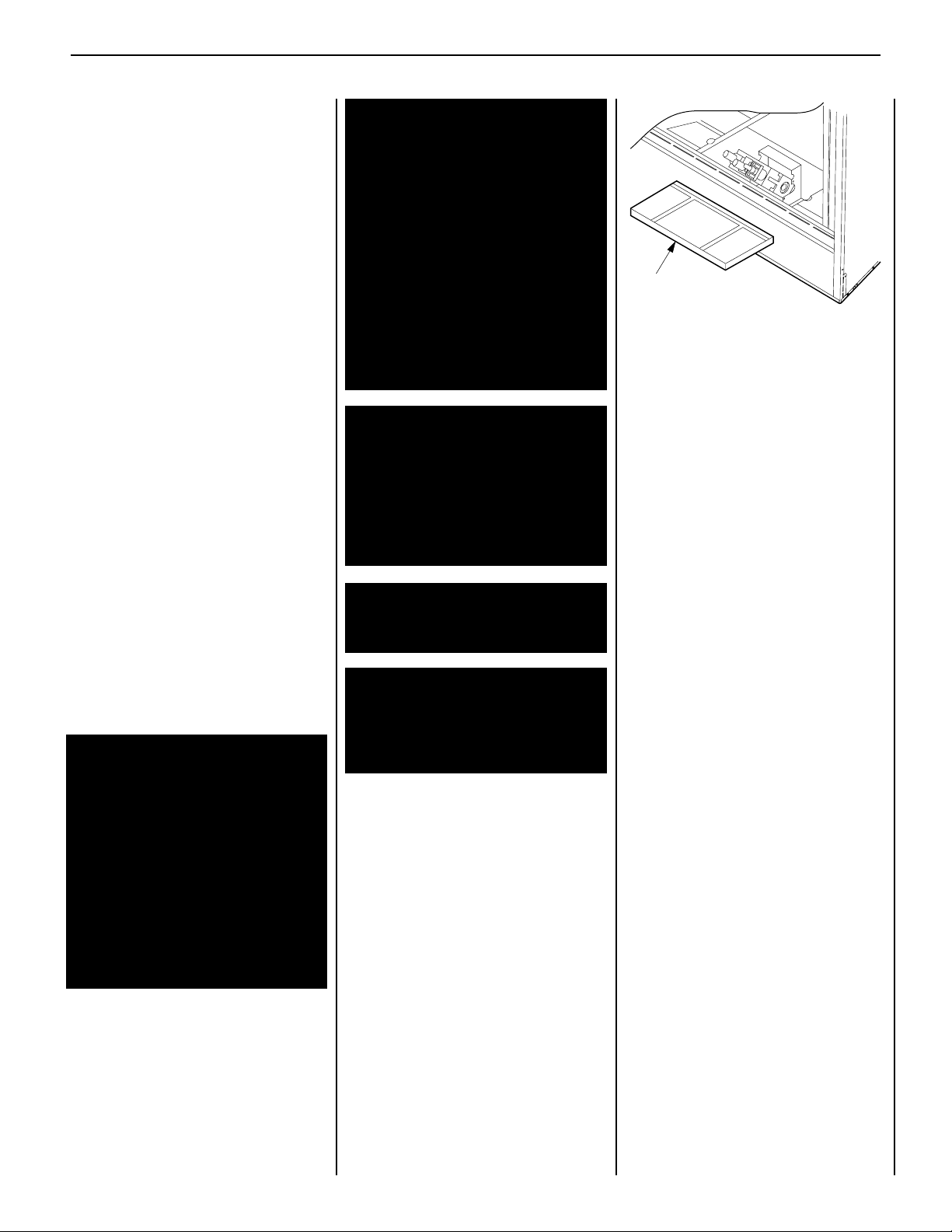
Refractory
Access Panel
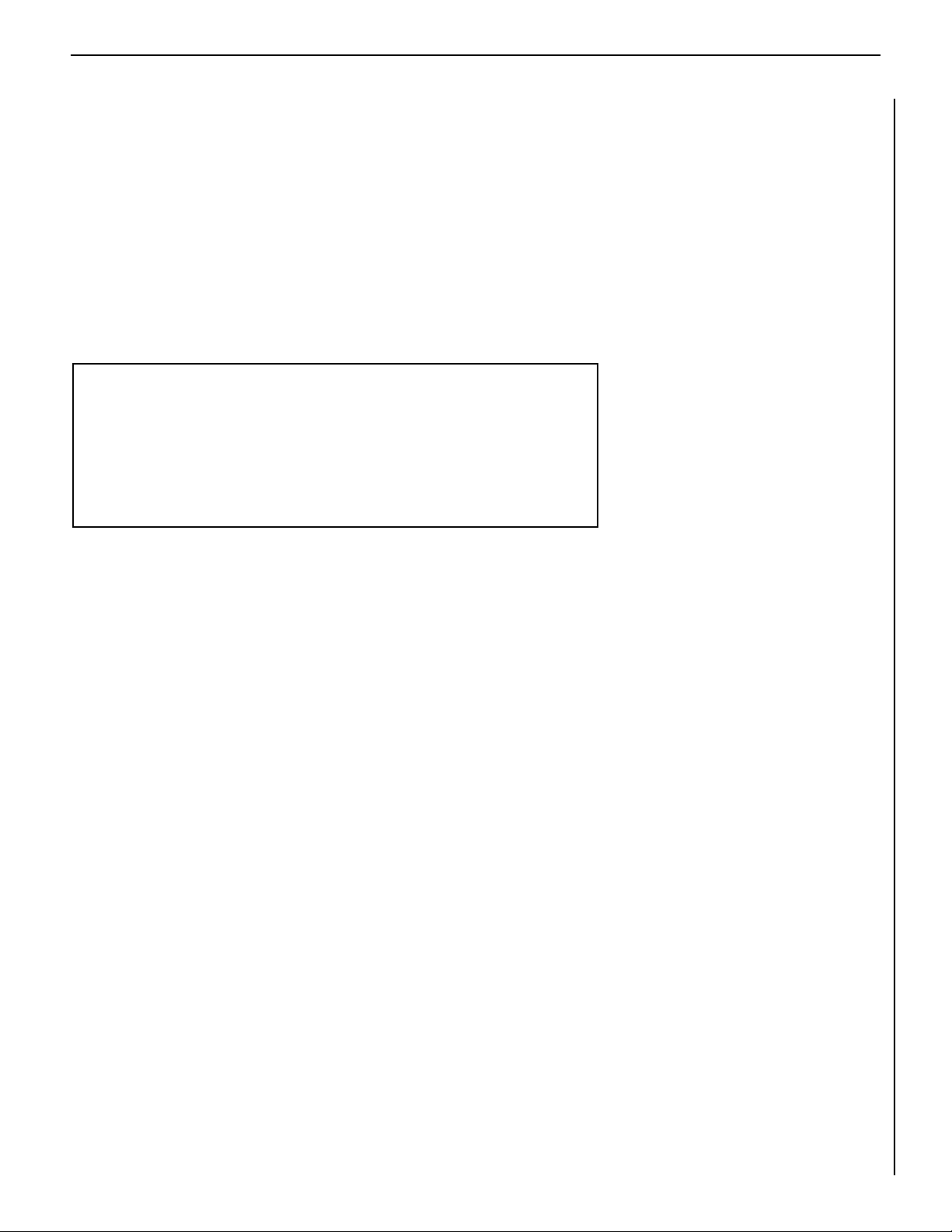
SIT Valve
Shown
Millivolt appliances may be tted at time of
manufacture with either a Honeywell millivolt
gas control valve or as SIT millivolt gas control
valve. Both valves have been tested with and
approved for use with these appliances and are
listed accordingly.
Test gage connections are provided on the front
of the millivolt gas control valves (identied OUT
for the manifold side and IN for inlet pressure
side for both SIT and Honeywell equipped
appliances.
Minimum inlet gas pressure to the appliance is
5.0 inches water column (9.5 MmHg) for natural
gas and 11 inches water column (20.55 MmHg)
for propane for the purpose of input adjustment.
Maximum inlet gas supply pressure to the
appliance is 10.5 inches water column (19.95
MmHg) for natural gas and 13.0 inches water
column (24.25 MmHg) for propane.
The appliance must be isolated from the gas
supply piping system (by closing its individual
manual shut-off valve) during any pressure testing
of the gas supply piping system at test pressures
equal to or less than 1/2 psig (3.5 kPa).
The appliance and its individual shut-off valve
must be disconnected from the gas supply
piping system during any pressure testing of
that system at pressures in excess of 1/2 psig
(3.5 kPa).
These appliances must not be connected to a
chimney or flue serving a separate solid fuel
burning appliance.
WARNING: FAILURE TO COMPLY WITH
THE INSTALLATION AND OPERATING
INSTRUCTIONS PROVIDED IN THIS
DOCUMENT WILL RESULT IN AN IMPROPERLY INSTALLED AND OPERATING
APPLIANCE, VOIDING ITS WARRANTY.
ANY CHANGE TO THIS APPLIANCE AND/
OR ITS OPERATING CONTROLS IS DANGEROUS. IMPROPER INSTALLATION OR
USE OF THIS APPLIANCE CAN CAUSE
SERIOUS INJURY OR DEATH FORM
FIRE, BURNS, EXPLOSION OR CARBON
MONOXIDE POISONING.
Carbon Monoxide Poisoning: Early signs
of carbon monoxide poisoning are similar
to the flu with headaches, dizziness and/
or nausea. If you have these signs, obtain
fresh air immediately. Turn off the gas supply to the appliance and have it serviced by
a qualified professional, as it may not be
operating correctly.
WARNING: B-VENT APPLIANCES ARE
NOT DESIGNED TO OPERATE IN NEGATIVELY PRESSURED ENVIRONMENTS
(PRESSURE WITHIN THE HOME IS
LESS THAN PRESSURES OUTSIDE).
SIGNIFICANT NEGATIVELY PRESSURED
ENVIRONMENTS CAUSED BY WEATHER,
HOME DESIGN, OR OTHER DEVICES MAY
IMPACT THE OPERATION OF THESE APPLIANCES. NEGATIVE PRESSURES MAY
RESULT IN POOR FLAME APPEARANCE,
SOOTING, DAMAGE TO PROPERTY AND/
OR SEVERE PERSONAL INJURY. DO NOT
OPERATE THESE APPLIANCES IN NEGATIVELY PRESSURED ENVIRONMENTS.
WARNING: CHILDREN AND ADULTS
SHOULD BE ALERTED TO THE HAZARDS
OF HIGH SURFACE TEMPERATURES. USE
CAUTION AROUND THE APPLIANCE TO
AVOID BURNS OR CLOTHING IGNITION.
YOUNG CHILDREN SHOULD BE CAREFULLY SUPERVISED WHEN THEY ARE
IN THE SAME ROOM AS THE APPLIANCE.
WARNING: DO NOT PLACE CLOTHING
OR OTHER FLAMMABLE MATERIALS ON
OR NEAR THIS APPLIANCE.
AVERTISSEMENT: SURVEILLER LES
ENFANTS. GARDER LES VÊTEMENTS,
LES MEUBLES, L'ESSENCE OU AUTRES
LIQUIDES À VAPEUR INFLAMMABLES
LIN DE L'APPAREIL.
OPERATION AND CARE OF YOUR
APPLIANCE
1. Appliance operation may be controlled
through a remotely located wall switch (nt
supplied) or optional remote control kit. In lieu
of remote wall switch operation, the appliance
must be operated directly through the controls
located on the front of the valve located within
the control compartment under the removable
refractory access panel, Figure 1.
Operation of millivolt and electronic gas control
systems are different. Before lighting and operating your appliance determine if you have a
millivolt or electronic appliance. Refer to Figure
1 to access the gas control compartment below
the lower refractory panel.
Figure 1
Millivolt appliances will be tted with the gas
control valve shown in Figure 2 on page 4.
Appliances with electronic systems will be tted
with the electronic valve shown in Figure 3 on
page 4. Familiarize yourself with the differing
controls for the valve your appliance uses.
To light millivolt appliances refer to the detailed
lighting instructions found in both English and
French on pages 12 and 13 of these instructions
respectively. Millivolt and electronic appliance
lighting instructions may also be found on the
pull out rating plate located within the gas
control compartment. Refer to Figure 2 for the
spark ignitor location used with your appliance.
If your millivolt appliance is equipped with an
optional remote wall switch or remote control
kit the appliance main burner may be turned on
and off with the wall switch or remote control.
If the appliance is not equipped with a wall or
remote control, the main burner must be turned
off and on with the gas control knob. Turn the
knob counter-clockwise from the PILOT position
to ON to light the main burner, and clockwise
from ON to PILOT to turn off the main burner.
To light electronic appliances refer to the
detailed lighting instructions found in both
English and French on pages 14 and 15 of
these instructions respectively. Millivolt and
electronic appliance lighting instructions
may also be found on the pull out rating plate
located within the gas control compartment.
If your electronic appliance is equipped with an
optional remote wall switch or remote control kit
the appliance main burner may be turner on and
off with the wall switch or remote control. If the
appliance is not equipped with a wall switch or
remote control, the main burner must be turned
off and on with the gas control switch. Toggle
the switch from ON to OFF to operate the main
burner from ON to OFF.
3
NOTE: DIAGRAMS & ILLUSTRATIONS ARE NOT TO SCALE.
Page 4
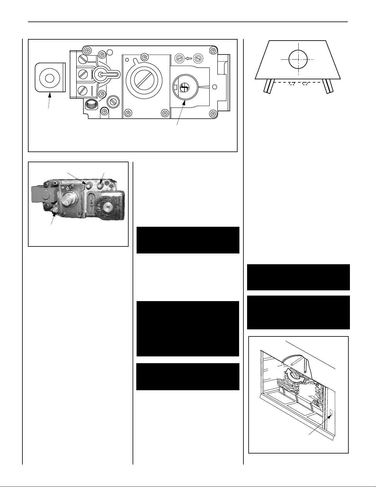
Figure 2
SIT Millivolt Valve
Gas Control
Knob
Piezo
Ignitor
E A
TPTH TP TH
P
I
L
O
T
P
I
L
O
T
O
N
it
O
F
F
Locked
Open
Locked
Closed
Outside Air
Actuator
Manifold Gauge Port
LENNOX CRESTLINE™ SERIES B-VENT GAS FIREPLACES • 36"/42" LSBV MODELS • CARE AND OPERATION INSTRUCTIONS
Fully Open or
Fully Closed
Figure 4
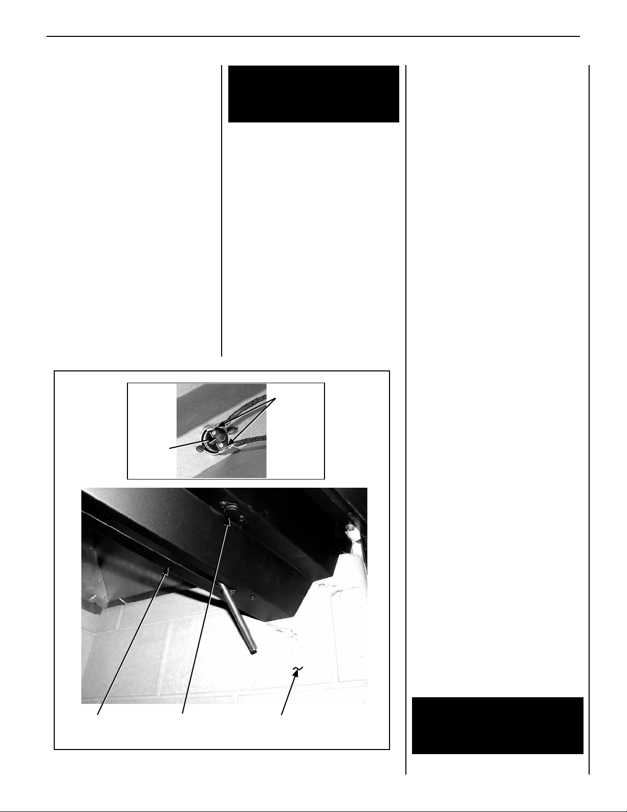
DAMPER AND OUTSIDE AIR CONTROLS
This appliance is tted with a manually controlled
vent damper. The vent damper should be closed
when the appliance is not in use to prevent cold
air from entering the home through the venting
system. The damper is controlled through the
use of a control lever located within the appliance opening at the top center in front of the
rebox lintel (see Figure 5 ). The control lever
snaps into place at either extreme of its range
of motion. When locked in position all the way
to the right, the damper is open. When locked
in position all the way to the left, the damper
is closed.
Inlet Gauge Port
6. Remember, Millivolt appliances have a con-
tinuous burning pilot flame. Exercise caution
when using products with combustible vapors.
7. Clean the optional glass doors only when
necessary. Wipe surface with clean, dampened,
soft cloth. Follow with dry, soft towel as desired.
Take care not to scratch the glass surface.
Pilot Adjustment Screw
Figure 3
2. When lit for the rst time, this appliance
will emit a slight odor for an hour or two. This
is due to the “burn-in” of internal paints and
lubricants used in the manufacturing process.
3. Keep lower control compartment clean by
vacuuming or brushing at least twice a year.
More frequent cleaning may be required due to
excessive lint from carpeting, bedding materials,
etc. It is important that control compartments,
burners and circulating air passageways of the
appliance be kept clean.
4. Always turn off gas to the pilot (millivolt
appliances) before cleaning. Before re-lighting,
refer to the lighting instructions in this manual.
Instructions are also found on a pull-out panel
located on the floor of the appliance.
5. Always keep the appliance area clear and
free from combustible materials, gasoline and
other flammable liquids.
WARNING: DO NOT USE ABRASIVE
CLEANERS. NEVER CLEAN THE GLASS
WHEN IT IS HOT.
CAUTION: DO NOT ATTEMPT TO TOUCH THE
DOORS WITH YOUR HANDS WHILE THE
FIREPLACE IS IN USE. ALWAYS USE DOOR
HANDLES. DOORS WILL BECOME VERY HOT
WHEN FIREPLACE IS IN USE.
WARNING: FIREPLACES EQUIPPED
WITH OPTIONAL ACCESSORY DOORS
SHOULD BE OPERATED ONLY WITH THE
DOORS FULLY OPEN OR FULLY CLOSED
(FIGURE 4 ). THIS APPLIANCE MAY
ONLY BE FITTED WITH DOORS CERTIFIED FOR USE WITH THE APPLIANCE.
AVERTISSEMENT: POUR UTILISATION
UNIQUEMENT AVEC LES PORTES EN
VERRE CERTIFIÊES AVEC L'APPAREIL.
The damper lever actuates a switch, (see wiring
diagram) which will prevent the appliance main
burner from lighting unless the damper is locked
open. The appliance flue damper must always
remain open when operating.
WARNING: DAMPER MUST BE IN OPEN
POSITION WHEN APPLIANCE MAIN
BURNER IS OPERATING.
AVERTISSEMENT: LE REGISTRE DOIT
ÊTRE EN POSITION OUVERTE LORSQUE
LE OU LES BRULEURS PRINCIPAUX DE
L'APPEREIL FONCTIONNMENT.
4
NOTE: DIAGRAMS & ILLUSTRATIONS ARE NOT TO SCALE.
Figure 5
Page 5
LENNOX CRESTLINE™ SERIES B-VENT GAS FIREPLACES • 36"/42" LSBV MODELS • CARE AND OPERATION INSTRUCTIONS
Detail A
Manual Reset
Limit Switch
Lintel
Extension
Right Side
Refractory Panel
Reset
Button
Wire
Terminals
The appliance is equipped with an outside
(make-up air) vent system that is designed to
provide the appliance with outside make-up air
for combustion when in operation. The shutoff lever for the outside air system is standard
on all appliances but should not be operated
if the complete system is not installed. Refer
to Figure 5. Outside air kits are not required
in all municipalities and may not be installed
or active with your appliance.
If you have reason to believe that you do
not have a complete outside air system, contact your distributor to have your appliance
inspected for the presence of the complete
system. DO NOT assume that you have this
system in place.
The hand operated shut-off lever is located in
the right side of the replace opening behind
the screen. To open, lift and pull all the way.
The outside air damper should be open when
the replace is in use and completely closed
when the replace is not being used. This
will prevent outside cold air from entering
the dwelling.
WARNING: DO NOT OPERATE THE
SHUTOFF LEVER UNLESS A COMPLETE
OUTSIDE AIR VENT SYSTEM HAS BEEN
INSTALLED WITH YOUR APPLIANCE.
MANUALLY-RESET BLOCKED FLUE SAFETY
SWITCH
This appliance is equipped with a manuallyreset blocked flue safety switch. Refer to
Figure 6 for its location. If during appliance
operation, the ame goes off (independently of
the burner on/off wall switch), it may be due to
the operation of this safety limit switch. First
allow the appliance to cool, then reset the
safety switch by pushing the red reset button.
This reset button is located on the back of the
limit switch, between the wire terminals (see
Detail A of Figure 6 ).
The appliance should then relight and remain
lit. If this does not occur, turn off the appliance and call a qualified service technician.
Maintenance
The appliance and venting system should be
thoroughly inspected before initial use and at
least annually by a qualied service technician.
Proper maintenance and use will require more
frequent, less extensive inspections and servicing by the homeowner.
Generally, annual inspections should be performed by a qualied service technician. More
frequent periodic inspections and cleanings
should be performed by the homeowner. Any
discrepancies discovered by the homeowner
should result in a call to a qualied service
technician to effect the repair or correction.
Refer to the maintenance schedule for main-
tenance tasks, procedures, periodicity and by
whom they should be performed.
IMPORTANT: TURN OFF GAS AND ANY
ELECTRICAL POWER BEFORE SERVICING
THE APPLIANCE.
Burner Adjustments
Flame Appearance and Sooting
Figure 6
Proper flame appearance is a matter of taste.
Generally most people prefer the warm glow of
a yellow to orange flame. Appliances operated
with air shutter openings that are too large, or
with long vertical vent runs, will exhibit ames
that are blue and transparent. These weak, blue
and transparent flames are termed anemic.
If the air shutter opening is too small sooting
may develop. Sooting is indicated by black puffs
developing at the tips of very long orange flames.
Sooting results in black deposits forming on the
logs, appliance inside surfaces and on exterior
surfaces adjacent to the vent termination. Sooting is caused by incomplete combustion in the
flames and a lack of combustion air entering
the air shutter opening.
To achieve a warm yellow to orange flame with
an orange body that does not soot, the shutter
opening must be adjusted between these two
extremes.
No smoke or soot should be present. Reposition
the log set if the flames impinge on any of them.
If sooting conditions exist, the air shutter
opening on the main burner can be adjusted.
Normally, the more offsets in the vent system,
the greater the need for the air shutter to be
opened further.
WARNING: AIR SHUTTER ADJUSTMENT
SHOULD ONLY BE PERFORMED BY A
QUALIFIED PROFESSIONAL SERVICE
TECHNICIAN.
5
NOTE: DIAGRAMS & ILLUSTRATIONS ARE NOT TO SCALE.
Page 6
LENNOX CRESTLINE™ SERIES B-VENT GAS FIREPLACES • 36"/42" LSBV MODELS • CARE AND OPERATION INSTRUCTIONS
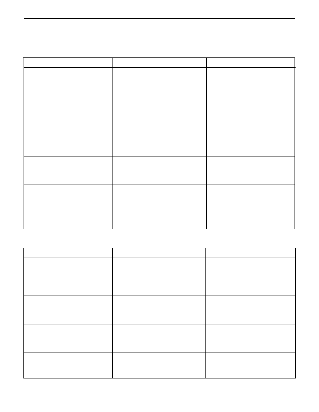
Maintenance Schedule
Annually (Before the onset of the Burning Season)
Maintenance Task Accomplishing Person Procedure
Inspecting/Cleaning Burner, Logs
and Controls
Check Flame Patterns and Flame Height
Inspecting/Cleaning Pilot and Burner
Checking Vent System
Appliance Checkout
Replacing Glowing Ember (Rockwool)
Materials
Qualied Service Technician
Qualied Service Technician
Qualied Service Technician
Qualied Service Technician
Qualied Service Technician
Homeowner/Qualied Services Technician
Inspect valve and ensure it is properly operating. Check piping for leaks. Vacuum the control
compartment, replace logs and burner area.
Refer to Figure 8 on page 8 and verify the
flame pattern and height displayed by the
appliance conforms to the picture. Flames
must not impinge on the logs.
Refer to Figure 9 on page 8. Remove any
surface build-up on pilot and burner assembly.
Wipe the pilot nozzles, ignitor/ame rod and
hood. Ensure the pilot flame engulfs the flame
sensor as shown.
Inspect the vent system at the top and at the
base (within the rebox) for signs of blockage
or obstruction. Look for any signs of dislocation of the vent components.
Perform the appropriate appliance checkout
procedure detailed in this manual.
Remove old ember materials and vacuum
the area for placement of glowing embers
(rockwool). Place new rockwool as described
in this document.
Periodically (After the Burning Season)
Maintenance Task Accomplishing Person Procedure
Cleaning Firebox Interior
Homeowner
Carefully remove logs, glowing embers (rockwool), and volcanic stone, if used. Vacuum
interior of the rebox. Clean rebox walls
and log grate. Replace logs, glowing embers
(rockwool), and volcanic stone, as detailed in
this manual.
Check Flame Patterns and Flame Height
Homeowner
Refer to Figure 8 on page 8 and verify the
flame pattern and height displayed by the appliance conforms to the picture. Flames must
not impinge on the logs.
Checking Vent System
Homeowner
Inspect the vent system at the top and at the
base (within the rebox) for signs of blockage
or obstruction. Look for any signs of dislocation
of the vent components.
Cleaning Optional Glass Doors
Homeowner
Clean as necessary following the directions
provided in this manual. DO NOT TOUCH OR
ATTEMPT TO CLEAN DOORS WHILE THEY
ARE HOT.
6
NOTE: DIAGRAMS & ILLUSTRATIONS NOT TO SCALE.
Page 7
LENNOX CRESTLINE™ SERIES B-VENT GAS FIREPLACES • 36"/42" LSBV MODELS • CARE AND OPERATION INSTRUCTIONS
Un foyer chaud peut causer
de graves brûlures
Ne laissez jamais un enfant
toucher à la vitre ou à toutes
autres parties du foyer
AVERTISSEMENT
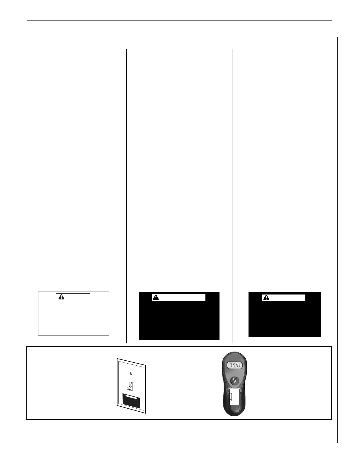
HOMEOWNER’S INSTRUCTIONS - ATTACHING "SAFETY-IN-OPERATION" WARNINGS
ATTACHING SAFETY IN OPERATION WARNINGS
Your replace has been furnished with safety instruction labels that are to be afxed to the operation and
control point of the replace. A safety instruction
label should be afxed to the wall switch plate where
the replace is turned on and off (See Figure A) and
if used on the remote control handheld transmitter
(Figure B). The warnings should already have been
put in place when the replace initial set-up was
completed. If they are not afxed at these spots,
locate the multi-lingual adhesive labels provided
with these instructions and proceed as follows:
1. Locate the wall switch that controls the replace
(verify the switch operates the replace by turn-
ing it on and off). Clean the wall switch plate
thoroughly to remove any dust and oils. Afx the
label to the surface of the plate of the wall switch
that controls the replace (Figure A). Choose
the language primarily spoken in the home.
2. If a remote control is used to control the replace,
locate the transmitter and clean it thoroughly
to remove any dust and oils. Afx the label to
the surface of handheld transmitter (Figure B).
Choose the language primarily spoken in the
home.
3. If you are unable to locate the labels, please call
Lennox Hearth Products or your nearest Lennox
Hearth Products dealer to receive additional
safety instruction labels free of charge.
Cat. No. H8024 Replacement Label Kit
LENNOX HEARTH PRODUCTS
1-800-9-LENNOX
Note: English is red text on clear label. French and
Spanish are white text on black label.
APPOSITION DES MISES EN GARDE RELATIVES
À LA SÉCURITÉ D’UTILISATION
Votre foyer a été livré avec des étiquettes de sécurité qui
doivent être collées à côté des dispositifs de contrôle
du foyer. Une étiquette de sécurité devrait être collée
sur la plaque de l’interrupteur contrôlant l’allumage du
foyer (voir Figure A) et, le cas échéant, sur le boîtier
de la télécommande (Figure B). Les mises en garde
auraient dû être collées au moment de l’installation
initiale du foyer. Si ce n’est pas le cas, prenez les
étiquettes adhésives multilingues fournies avec ces
instructions et procédez comme suit:
1. Repérez l’interrupteur qui contrôle le foyer (vériez
que l’interrupteur contrôle le fonctionnement du
foyer en le faisant basculer de Marche à Arrêt, et
vice-versa). Nettoyez soigneusement la plaque
murale de l’interrupteur pour éliminer la poussière
et les traces de graisse ou d’huile. Collez l’étiquette
sur la surface de la plaque de l’interrupteur mural
qui contrôle le foyer (Figure A). Choisissez la langue
qui est principalement parlée dans la résidence
du propriétaire.
2. Si une télécommande est utilisée pour contrôler
le foyer, nettoyez la soigneusement pour éliminer
la poussière et les traces de graisse ou d’huile.
Collez l’étiquette sur le boîtier de la télécommande
(Figure B). Choisissez la langue qui est principale-
ment parlée dans la résidence du propriétaire.
3. Si vous ne trouvez pas les étiquettes, veuillez
appeler Lennox Hearth Products ou votre distributeur Lennox Hearth Products local pour recevoir
gratuitement des étiquettes supplémentaires.
Étiquettes de remplacement, n° cat. H8024
LENNOX HEARTH PRODUCTS
1-800-9-LENNOX
Remarque : Le texte anglais est rouge sur un support
transparent. Le texte français et espagnol est blanc
sur un support noir.
COLOCACIÓN DE ADVERTENCIAS DE SEGURIDAD
EN OPERACIÓN
Su chimenea incluye etiquetas de instrucciones de
seguridad que deben colocarse en el punto de operación
y control de la chimenea. Se debe colocar una etiqueta
de instrucciones de seguridad en la placa del interruptor
de pared desde el cual se enciende y se apaga la
chimenea (ver la Figura A) y en el transmisor de control
remoto (Figura B) si se usa. Las advertencias ya deben
haberse colocado cuando se completó la instalación
inicial de la chimenea. Si no están colocadas en estos
lugares, encuentre las etiquetas adhesivas multilingües
proporcionadas con estas instrucciones y prosiga de
la siguiente manera:
1. Identique el interruptor de pared que controla
la chimenea (verique que el interruptor opera la
chimenea encendiéndola y apagándola). Limpie
bien la placa del interruptor de pared para quitar el
polvo y aceite. Pegue la etiqueta en la supercie de
la placa del interruptor que controla la chimenea
(Figura A). Seleccione el idioma que más se habla
en la casa.
2. Si se usa un control remoto para controlar la
chimenea, encuentre el transmisor y límpielo bien
para quitar el polvo y aceite. Pegue la etiqueta en la
supercie del transmisor (Figura B). Seleccione el
idioma que más se habla en la casa.
3. Si no puede encontrar las etiquetas, sírvase llamar a
Lennox Hearth Products o al distribuidor de Lennox
Hearth Products más cercano para recibir etiquetas
de instrucciones de seguridad adicionales gratuitas.
Juego de etiquetas de repuesto - Nº de cat. H8024
LENNOX HEARTH PRODUCTS
1-800-9-LENNOX
Nota: La etiqueta en inglés es transparente con texto
rojo. Las etiquetas en francés y español son negras
con texto blanco.
SAFETY LABEL DIAGRAMS
WARNING
Hot Fireplace Will Cause
Severe Burns
Never Allow Children to
Touch Glass or other Fireplace Parts
Figure A
DIAGRAMMES DES ÉTIQUETTES DE SÉCURITÉ DIAGRAMAS DE ETIQUETAS DE SEGURIDAD
AVERTISSEMENT
Un foyer chaud peut causer
de graves brûlures
Ne laissez jamais un enfant
toucher à la vitre ou à toutes
autres parties du foyer
Figure B
NOTE: DIAGRAMS & ILLUSTRATIONS ARE NOT TO SCALE.
WARNING
Hot Fireplace Will Cause
Severe Burns
Never Allow Children to
Touch Glass or other Fire-
La chimenea caliente
causará quemaduras graves
Nunca permita que los niños
toquen el vidrio ni otras
partes de la chimenea
place Parts
ADVERTENCIA
7
Page 8
LENNOX CRESTLINE™ SERIES B-VENT GAS FIREPLACES • 36"/42" LSBV MODELS • CARE AND OPERATION INSTRUCTIONS
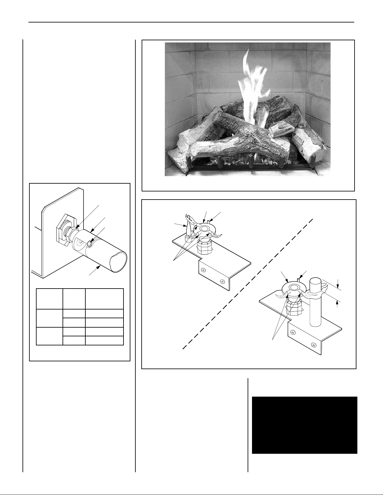
Orifice
Air Shutter
Burner Tube
Adjusting
Set Screw
MILLIVOLT
ELECTRONIC
Hood
Ignitor Rod
Pilot
Nozzels
Flame
Sensor
3/8 Min
(9 mm)
Hood
Pilot
Nozzels
Ignitor Rod
Adjustment
To adjust the ame, position the air shutter
to the nominal setting (see Figure 7 ). Allow
the burner to operate for at least 30 minutes.
Observe the flame continuously.
If it appears weak or sooty as previously de-
scribed, adjust the air shutter open or closed
until desired effect is achieved.
Note: If the flame still appears anemic with the
air shutter closed all the way (usually a result of
lengthy vertical venting runs), turn off the appliance, turn off the gas supply, wait for the parts
to cool and access the air shutter. The shutter is
prevented from actually closing by a tab that is
bent over into the opening. Remove this obstruction by bending back. Reassemble and restart
the appliance and after 24 minutes reobserve
the flame. Adjust the air shutter as described.
Figure 8
8
Factory Air
Models Shutter Setting
Inches (mm)
LSBV-3628
LSBV-4228
Figure 7
Gas
Type
Natural 1/8" (3.175 mm)
Propane 1/2" (12.7 mm)
Natural 1/8" (3.175 mm)
Propane 1/2" (12.7 mm)
Millivolt Appliance Checkout
The pilot ame should be steady, not lifting
or floating. Flame should be blue in color with
traces of orange at the outer edge.
The top 3/8" (9 mm) at the pilot generator
(thermopile) should be engulfed in the pilot
ame. The ame should project 1" (25 mm)
beyond the hood at all three ports (Figure 9 Millivolt section).
Figure 9
Electronic Appliance Checkout
Light the burner, refer to the Lightilng Instructions in this manual. Ensure the ignitor lights
the pilot. The pilot flame should engulf the flame
rod as shown in Figure 9 - Electronic section.
With proper care and maintenance, your appliance will provide many years of enjoyment. If
you should experience any problem, rst refer
to the trouble shooting guide in this manual. If
problem persists, contact your Lennox Dealer.
NOTE: DIAGRAMS & ILLUSTRATIONS ARE NOT TO SCALE.
Logs and Glowing Embers (Rockwool)
Placement
WARNING: LOGS GET VERY HOT AND
WILL REMAIN HOT UP TO ONE HOUR
AFTER GAS SUPPLY IS TURNED OFF.
HANDLE ONLY WHEN LOGS ARE COOL.
TURN OFF ALL ELECTRICITY TO THE APPLIANCE BEFORE YOU INSTALL GRATE
AND LOGS.
Page 9

LENNOX CRESTLINE™ SERIES B-VENT GAS FIREPLACES • 36"/42" LSBV MODELS • CARE AND OPERATION INSTRUCTIONS
Logs and Rockwool Placement
WARNING: LOGS GET VERY HOT AND
WILL REMAIN HOT UP TO ONE HOUR
AFTER GAS SUPPLY IS TURNED OFF.
HANDLE ONLY WHEN LOGS ARE COOL.
TURN OFF ALL ELECTRICITY TO THE APPLIANCE BEFORE YOU INSTALL GRATE
AND LOGS.
WARNING: THIS APPLIANCE IS NOT
MEANT TO BURN WOOD. ANY ATTEMPT
TO DO SO COULD CAUSE IRREPARABLE
DAMAGE TO YOUR APPLIANCE AND
PROVE HAZARDOUS TO YOUR SAFETY.
WARNING: THE SIZE AND POSITION ON
THE LOG SET WAS ENGINEERED TO GIVE
YOUR APPLIANCE A SAFE, RELIABLE
AND ATTRACTIVE FLAME PATTERN.
ANY ATTEMPT TO USE A DIFFERENT
LOG SET IN THE FIREPLACE WILL VOID
THE WARRANTY AND WILL RESULT IN
INCOMPLETE COMBUSTION, SOOTING,
AND POOR FLAME QUALITY.
These appliances are equipped with a beautifully
crafted six (6) piece ceramic ber log set. The
logs, shown in Figure 8 on page 8, are to be
positioned precisely as shown. Any modication to the lay of the logs may result in sooting,
property damage and injury or death.
The rear log has mating holes for pin engagement on its bottom side. DO NOT force a hole
into a log by engaging the pins where they are
not intended to go.
Apparent minor mis-alignment of the pins and
holes or landings can be eliminated by gently
adjusting the position of the logs until the pins,
holes or landings easily mate.
Step 1. To position the logs, begin by placing
the rear log in position over the two pins located
at the left rear and right rear of the log grate,
see Figure 10 and Figure 11.
Rear Log
Step 3. Place the left log as shown in Figure
13, on the landing of the rear log. Make sure
the landing on the front end of the log is resting
on the rst left nger of the grate, as shown
in Figure 13.
Left Log
Left Grate Finger
Figure 13
Step 4. Position the center log, see Figure 14,
with the two branches sitting on the two landings
provided on the top of the left log. The other
end of the center log has a groove that should
t against the second right nger of the grate,
as shown in Figure 14.
Left Log Landings
Rear Log Landing
Proper log placement is critical to prevent soot-
ing. Carefully position the ceramic ber logs
over the burner as described in the following
steps, and detailed in Figures 10 through 15.
Note: Logs should be placed in the gaps between
the flame peaks and should be positioned so
that at no time they impinge the flames.
The logs are packaged within the rebox. The
Lava Rock (2 bags) and Rockwool (Glowing
Embers) (1 bag) are in the bottom of the
burner tray.
Spread 1-1/2 bags of Lava Rock evenly inside
of the burner tray, as shown in Figure 10. The
rest of the 1/2 bag of Lava Rock should be used
only on LSBV-42 models, placed on the open
spaces on the bottom of the rebox between
the refractory and burner tray.
Rear Log Pin
Vertical Brackets
Rear Log Pin
Figure 11
Step 2. Position the bottom log, (see Figure
10 and Figure 12 ) between the two vertical
brackets of the burner tray.
Remove the Rockwool from the plastic bag
and tear into quarter size pieces, as shown in
Figure 12. Spread across the front part of the
burner. Do Not use more than is necessary to
cover the burner. When properly positioned,
the Rockwool will unevenly cover approximately
85% of the burner with no appreciable gaps.
Bottom Log
Center Log
Figure 14
Step 5. Place the right log as shown in Figure
15, with the upper end sitting on the landing
provided on the rear log. Another end of the
right log should rest on the rst right nger of
the grate (see Figure 15 ). Position the top
right log as shown, locating it on the landing
of the center log.
Second Right Grate Finger
Top Right Log
Right Log
Figure 10
Lava Rock
Rockwool
Figure 12
NOTE: DIAGRAMS & ILLUSTRATIONS ARE NOT TO SCALE.
Log Grate
Center Log Landing
Figure 15
Right Grate Finger
9
Page 10

LENNOX CRESTLINE™ SERIES B-VENT GAS FIREPLACES • 36"/42" LSBV MODELS • CARE AND OPERATION INSTRUCTIONS
BLACK
BLACK
DAMPER SWITCH
LIMIT SWITCH
MILIVOLT WIRING DIAGRAM
TH
TP
TP
TH
THERMOPILE
WALL MOUNTED
ON/OFF SWITCH
GAS VALVE
BLACK
WHITE
WIRING DIAGRAMS
Wiring diagrams are provided here for reference purposes only. This information is also provided on schematics attached directly to the appliance
on a pullout panel located within the control compartment. Two Millivolt wiring diagrams are provided here, one each for both Honeywell and SIT
equipped systems.
PILOT BURNER
IGNITER-SENSOR
ASSEMBLY
CONNECTOR
BLUE
GROUND
GREEN
PURPLE
ELECTRONIC IGNITION
CONTROL BOARD
EV2
ORANGE
WHITE
WHITE
EV1
BLACK
GREEN LED
GAS VALVE
WHITE
WALL MOUNTED
ON/OFF SWITCH
ELECTRONIC WIRING DIAGRAM
W
BLACK
Plug blower
into this
receptacle
Tab Intact
Green
Ground
Screw
BK
DAMPER SWITCH
Green
Neutral
Side of
Receptacle
BLACK
White
Black
Red
Hot
Side of
Receptacle
LIMIT SWITCH
Tab
Broken
BLACK
TRANSF
120 V.
24 V.
CONNECTOR
120 VAC - Black
Junction Box
neerG-dnuorG
etihW-lartueN
10
NOTE: DIAGRAMS & ILLUSTRATIONS ARE NOT TO SCALE.
Page 11
LENNOX CRESTLINE™ SERIES B-VENT GAS FIREPLACES • 36"/42" LSBV MODELS • CARE AND OPERATION INSTRUCTIONS
WARRANTY
Your gas appliance is covered by a limited twenty
year warranty. You will nd a copy of the war-
ranty accompanying this manual. Please read
the warranty to be familiar with its coverage.
Retain this manual. File it with your other documents for future reference.
REPLACEMENT PARTS
A complete parts list is found at the end of
this manual. Use only parts supplied from the
manufacturer.
Normally, all parts should be ordered through
your Lennox distributor or dealer. Parts will be
shipped at prevailing prices at time of order.
PRODUCT REFERENCE INFORMATION
We recommend that you record the following important information about your replace. Please
contact your Lennox dealer for any questions or concerns. For the number of your nearest Lennox
dealer, please call 1-800-9-LENNOX.
Fireplace Model Number _____________________________________________
Fireplace Serial Number ______________________________________________
Date Fireplace Was Installed __________________________________________
Type of Gas Used in Fireplace _________________________________________
Your Dealer's Name ________________________________________________
When ordering repair parts, always give the
following information:
1. The model number of the appliance.
2. The serial number of the appliance.
3. The part number.
4. The description of the part.
5. The quantity required.
6. The installation date of the appliance.
If you encounter any problems or have any questions concerning the installation or application
of this system, please contact your distributor,
or Lennox directly:
LENNOX HEARTH PRODUCTS
1508 Elm Hill Pike, Suite 108
Nashville, TN 37210
NOTE: DIAGRAMS & ILLUSTRATIONS ARE NOT TO SCALE.
11
Page 12

LENNOX CRESTLINE™ SERIES B-VENT GAS FIREPLACES • 36"/42" LSBV MODELS • CARE AND OPERATION INSTRUCTIONS
SIT
MILLIVOLT PILOT
E A
TPTH TP TH
P
I
L
O
T
P
I
L
O
T
O
N
it
O
F
F
LIGHTING INSTRUCTIONS – SIT MILLIVOLT GAS VALVE
FOR YOUR SAFETY READ BEFORE LIGHTING
WARNING: IF YOU DO NOT FOLLOW THESE INSTRUCTIONS EXACTLY, A FIRE OR EXPLOSION
MAY RESULT CAUSING PROPERTY DAMAGE, PERSONAL INJURY OR LOSS OF LIFE.
A. This appliance has a pilot which must be lighted with a piezo
ignitor. When lighting the pilot, follow these instructions
exactly.
B. BEFORE OPERATING smell all around the appliance area for
gas. Be sure to smell next to the floor because some gas is
heavier than air and will settle on the floor.
WHAT TO DO IF YOU SMELL GAS
• Extinguish any open flame.
• Open windows.
• Do not light any appliance.
• Do not touch any electrical switches.
LIGHTING INSTRUCTIONS
1. STOP! Read the safety information above on this page.
2. Access the lower control compartment.
3. Turn remote wall switch to “OFF.”
4. Verify main line shut-off valve is open.
5. Push in gas control knob slightly and turn clockwise
to “OFF.”
• Do not use any phone in your building.
• Immediately call your gas supplier from a neighbor’s phone.
• If your gas supplier cannot be reached, call the re depart-
ment.
C. Use only your hand to push in or turn the gas control knob.
Never use tools. If the knob will not push in or turn by hand,
do not try to repair it, call a qualied service technician. Force
or attempted repair may result in a re or an explosion.
D. Do not use this appliance if any part has been under water.
Immediately call a qualied service technician to inspect the
appliance and to replace any part of the control system and
any gas control which has been under water.
6. Wait ve (5) minutes to clear out any gas. If you then smell gas,
STOP! Follow “B” in the safety information above on this page. If you
do not smell gas, go to the next step.
7. Push in gas control knob slightly and turn counterclockwise
to “PILOT.”
8. Push in control knob all the way and hold in. Immediately light the
pilot by triggering the spark ignitor (pushing the button) until pilot
lights. Continue to hold the control knob in for about 1 ¹⁄₂ minutes
after the pilot is lit. Release knob and it will pop back up. Pilot should
remain lit. If it goes out, repeat steps 5
through 8.
12
SIT
MILLIVOLT
GAS VALVE
Note: Knob cannot be turned from “PILOT” to “OFF”
unless the knob is pushed in slightly. Do not force.
TO TURN OFF GAS TO APPLIANCE
1. Turn remote wall switch “OFF.” The pilot will remain lit for
normal service.
2. For complete shutdown, turn remote wall switch to “OFF.”
3. Access the lower control compartment.
NOTE: DIAGRAMS & ILLUSTRATIONS ARE NOT TO SCALE.
• If knob does not pop up when
released, stop and immediately call
your service technician or gas supplier.
• If pilot will not stay lit after several
tries, turn the control knob to “OFF”
and call your service technician or
gas supplier.
9. Turn gas control knob counterclockwise to “ON.”
10. Close lower control compartment.
4. Depress gas control knob slightly and turn clockwise
to “OFF.” Do not force.
5. Close lower control compartment.
Page 13

LENNOX CRESTLINE™ SERIES B-VENT GAS FIREPLACES • 36"/42" LSBV MODELS • CARE AND OPERATION INSTRUCTIONS
SIT
MILLIVOLT PILOT
E A
TPTH TP TH
P
I
L
O
T
P
I
L
O
T
O
N
it
O
F
F
INSTRUCTIONS D’ALLUMAGE – VANNE GAZ MILLIVOLT SIT
POUR VOTRE SÉCURITÉ, LISEZ CES INSTRUCTIONS AVANT L’ALLUMAGE
AVERTISSEMENT : SI VOUS NE SUIVEZ PAS CES INSTRUCTIONS À LA LETTRE, IL POURRAIT S’EN SUIVRE UN INCENDIE OU
UNE EXPLOSION CAUSANT DES DOMMAGES MATÉRIELS, DES BLESSURES CORPORELLES OU MÊME DES PERTES DE VIE.
A. Cet appareil est muni d’une veilleuse qui doit être allumée avec un
allumeur piézo-électrique. Lorsque vous allumez la veilleuse, suivre
exactement ces instructions.
B. AVANT L’ALLUMAGE: Assurez-vous que vous ne détectez aucune odeur
de gaz autour de l’apareil ainsi que près du sol; certains gaz, étant plus
lourds que l’air, descendent au niveau du sol.
VOICI CE QUE VOUS DEVEZ FAIRE SI VOUS DÉCELEZ UNE ODEUR
DE GAZ:
• Éteignez toute flamme visible.
• Ouvrez les fenêtres.
• N’allumez aucun appareil.
• Ne touchez à aucun commutateur électrique.
• Ne vous servez d’aucun téléphone dans votre édice.
INSTRUCTIONS D'ALLUMAGE
• Appelez immédiatement votre compagnie de gaz en utilisant le téléphone du voisin.
• S’il vous est impossible de contacter votre compagnie de gaz, appelez
le service des incendies.
C. N’utilisez que votre main pour manipuler le bouton de réglage du gaz.
N’utilisez jamais d’outils. Si le bouton refuse de tourner ou de bouger,
n’essayez pas de le réparer. Communiquez immédiatement avec un
technicien de service qualié. Toute tentative pour le forcer ou le
réparer, risquerait de provoquer un incendie ou une explosion.
D. Ne vous servez pas de cet appareil si l’un de ses éléments a été
immergé dans l’eau. Appelez immédiatement un technicien compétent
pour faire inspecter l’appareil et remplacer toute pièce du système de
réglage ou commande du gaz qui a été sous l’eau.
1. ARRÊTEZ! Lisez les consignes de sécurité au verso de cette plaque.
2. Ouvrez le compartiment de contrôle du bas.
3. Tournez l’interrupteur mural à la position d’arrêt “OFF”.
4. Assurez-vous que la soupape d’arrêt de la canalisation principale est
ouverte.
5. Enfoncez légèrement le bouton de réglage du gaz et tournez-le dans
le sens des aiguilles d’une montre jusqu’à la position
d’arrêt “OFF”.
VANNE GAZ
MILLIVOLT SIT
Remarque: Il est impossible de tourner le bouton de “PILOT” à “OFF” à
moins qu’il ne soit légèrement enfoncé. Ne le forcez pas.
6. Attendez cinq (5) minutes pour l’evacuation du gaz. Si vous décelez
une odeur de gaz, ARRÊTEZ ! Retournez au point “B” des consignes
de sécurité au verso de cette plaque. Si vous ne remarquez aucune
odeur de gaz, passez à l’étape suivante.
7. Enfoncez légèrement le bouton de réglage du gaz et tournez-le en
sens inverse des aiguilles d’une montre jusqu’à la position de veilleuse “PILOT”.
8. Enfoncez le bouton de réglage jusqu’au fond et gardez-le
enfoncé. Allumez immédiatement la veilleuse en déclenchant
l’allume-gaz à étincelle (en poussant le bouton) jusqu’à ce que
la veilleuse s’enflamme. Continuez de tenir le bouton de réglage
enfoncé pendant environ 90 secondes après l’allumage de la
veilleuse. Relâchez le bouton et il sortira subitement. La veil-
leuse devrait rester allumée. Si elle s’éteint, répétez les étapes 5
à 8 inclusivement.
• Si le bouton ne sort pas automatiquement après avoir été relâché,
arrêtez immédiatement et téléphonez à votre technicien de service
ou à votre fournisseur de gaz.
• Si la veilleuse refuse de rester
allumée après plusieurs tentatives,
tournez le bouton de réglage jusqu’à
sa position d’arrêt “OFF” et téléphonez à votre technicien de service
ou à votre fournisseur de gaz.
9. Tournez le bouton de réglage du gaz
en sens inverse des aiguilles d’une
montre jusqu’à sa position de marche “ON”.
10. Fermez le compartiment de contrôle du bas.
11. Au besoin, rebrancher l’appareil au courant électrique et remettre
l’interrupteur du brûleur principal à la position “ON” ou régler le
thermostat à la température désirée.
12. Si l’appareil ne fonctionne pas, suivre les instructions intitulées
“Pour fermer le gaz qui alimente l’appareil” et appeler un technicien ou le fournisseur de gaz.
POUR FERMER LE GAZ QUI ALIMENTE L’APPAREIL
1. Tournez l’interrupteur mural à la position d’arrêt “OFF”. La veilleuse
restera allumée jusqu’au retour du service normal.
2. Pour une fermeture complète, tournez l’interrupteur mural à la posi-
tion d’arrêt “OFF”.
3. Ouvrez le compartiment de contrôle du bas.
NOTE: DIAGRAMS & ILLUSTRATIONS ARE NOT TO SCALE.
4. Enfoncez légèrement le bouton de réglage du gaz et tournez-le dans
le sens des aiguilles d’une montre jusqu’à la position
d’arrêt “OFF”. Ne forcez pas le bouton.
5. Fermez le compartiment de contrôle du bas.
13
Page 14

LENNOX CRESTLINE™ SERIES B-VENT GAS FIREPLACES • 36"/42" LSBV MODELS • CARE AND OPERATION INSTRUCTIONS
LIGHTING INSTRUCTIONS — ELECTRONIC
FOR YOUR SAFETY READ BEFORE LIGHTING
WARNING: IF YOU DO NOT FOLLOW THESE INSTRUCTIONS EXACTLY, A FIRE OR EXPLOSION
MAY RESULT CAUSING PROPERTY DAMAGE, PERSONAL INJURY OR LOSS OF LIFE.
A. When lighting the appliance, follow these instructions
exactly.
B. BEFORE OPERATING smell all around the appliance area
for gas. Be sure to smell next to the floor because some
gas is heavier than air and will settle on the floor.
WHAT TO DO IF YOU SMELL GAS
• Extinguish any open flame.
• Open windows.
• Do not light any appliance.
• Do not touch any electrical switches.
• Do not use any phone in your building.
LIGHTING INSTRUCTIONS
1. STOP! Read the safety information above on this page.
2. Turn remote wall switch to “OFF.”
3. Open lower control compartment door.
4. Verify main line shut-off valve is open.
5. Turn the ON/OFF switch to “OFF”. Do not force.
• Immediately call your gas supplier from a neighbor’s
phone.
• If your gas supplier cannot be reached, call the re
department.
C. Use only your hand to turn the gas control lever. Never
use tools. If the lever will not turn by hand, do not try
to repair it, call a qualied service technician. Force or
attempted repair may result in a re or an explosion.
D. Do not use this appliance if any part has been under
water. Immediately call a qualied service technician
to inspect the appliance and to replace any part of the
control system and any gas control which has been
under water.
6. Wait ve (5) minutes to clear out any gas. If you then
smell gas, STOP! Follow “B” in the safety information
above on this page. If you do not smell gas, go to the
next step.
7. Turn the ON/OFF switch to “ON”. Do not force.
8. Turn “ON” all electrical power to appliance (remote wall
switch).
14
Gas Valve
TO TURN OFF GAS TO APPLIANCE
1. For complete shut-down, turn remote wall switch to
“OFF.”
2. Open lower control compartment door.
NOTE: DIAGRAMS & ILLUSTRATIONS ARE NOT TO SCALE.
9. Close lower control compartment door.
TO SHUT OFF
1. Turn off all electrical power to the appliance (remote wall
switch).
3. Turn the ON/OFF switch to “OFF”. Do not force.
4. Close the main line shut-off valve.
5. Close lower control compartment door.
Page 15
LENNOX CRESTLINE™ SERIES B-VENT GAS FIREPLACES • 36"/42" LSBV MODELS • CARE AND OPERATION INSTRUCTIONS
INSTRUCTIONS D’ALLUMAGE — ELECTRONIC
POUR VOTRE SÉCURITÉ, LISEZ CES INSTRUCTIONS AVANT L’ALLUMAGE
AVERTISSEMENT: SI VOUS NE SUIVEZ PAS CES INSTRUCTIONS À LA LETTRE, IL POURRAIT S’EN SUIVRE UN INCENDIE OU
UNE EXPLOSION CAUSANT DES DOMMAGES MATÉRIELS, DES BLESSURES CORPORELLES OU MÊME DES PERTES DE VIE.
A. Lorsque vous allumez l’appareil, suivez exactement ces instruc-
tions.
B. AVANT L’ALLUMAGE: Assurez-vous que vous ne détectez
aucune odeur de gaz autour de l’apareil ainsi que près du sol;
certains gaz, étant plus lourds que l’air, descendent au niveau
du sol.
VOICI CE QUE VOUS DEVEZ FAIRE SI VOUS DÉCELEZ UNE
ODEUR DE GAZ
• Éteignez toute flamme visible.
• Ouvrez les fenêtres.
• N’allumez aucun appareil.
• Ne touchez à aucun commutateur électrique.
• Ne vous servez d’aucun téléphone dans votre édice.
INSTRUCTIONS D’ALLUMAGE
1. ARRÊTEZ ! Lisez les consignes de sécurité au verso de cette
plaque.
2. Tournez l’interrupteur mural à la position d’arrêt “OFF”.
3. Ouvrez la porte du compartiment de contrôle du bas.
4. Assurez-vous que la soupape d’arrêt de la canalisation principale
est ouverte.
• Appelez immédiatement votre compagnie de gaz en utilisant
le téléphone du voisin.
• S’il vous est impossible de contacter votre compagnie de
gaz, appelez le service des incendies.
C. N’utilisez que votre main pour manipuler linterrupteur
“ON/OFF” de la valve à gaz. N’utilisez jamais d’outils. Si
l’interrupteur ne bouge pas manuellement, n’essayez pas de le
réparer. Communiquez immèdiatement avec un technicien de
service qualié. Toute tentative pour forcer l’interrupteur ou le
réparer, risquerait de provoquer un incendie ou une explosion.
D. Ne vous servez pas de cet appareil si l’un de ses éléments a
été immergé dans l’eau. Appelez immédiatement un technicien
compétent pour faire inspecter l’appareil et remplacer toute
pièce du système de réglage ou commande du gaz qui a été
sous l’eau.
6. Attendez cinq (5) minutes pour l’evacuation du gaz. Si vous
décelez une odeur de gaz ARRÊTEZ ! Retournez au point “B”
des consignes de sécurité au verso de cette plaque. Si vous ne
remarquez aucune odeur de gaz, passez à l’étape suivante.
7. Tournez la manette de réglage du gaz jusqu’à la position de
marche “ON”. Ne la forcez pas.
8. Ouvrez le courant électrique (“ON”) qui alimente l’appareil
(interrupteur mural).
5. Tournez la manette de réglage du gaz à la position d’arrêt “OFF”.
Gas Valve
POUR FERMER LE GAZ QUI ALIMENTE L’APPAREIL
1. Pour une fermeture complète, tournez l’interrupteur mural à la
position d’arrêt “OFF”.
2. Ouvrez la porte du compartiment de contrôle du bas.
NOTE: DIAGRAMS & ILLUSTRATIONS ARE NOT TO SCALE.
9. Fermez la porte du compartiment de contrôle du bas.
10. Au besoin, rebrancher l’apareil au courant électrique et
remettre l’interrupteur principal du brûleur à la position “ON”
ou régler le thermostat à la température désirée.
11. Si l’appareil ne se met pas en marche, suivre les instruc-
tions intitulées “Pour fermer le gaz qui alimente l’appareil” et
appeler un technicien ou le fournisseur de gaz.
POUR ÉTEINDRE L’APPAREIL
1. Coupez tout le courant électrique qui alimente l’appareil (inter-
rupteur mural).
3. Tournez la manette de réglage du gaz à la position d’arrêt “OFF”.
Ne la forcez pas.
4. Fermez la soupape d’arrêt de la canalisation principale.
5. Fermez la porte du compartiment de contrôle du bas.
15
Page 16

LENNOX CRESTLINE™ SERIES B-VENT GAS FIREPLACES • 36"/42" LSBV MODELS • CARE AND OPERATION INSTRUCTIONS
TROUBLESHOOTING THE MILLIVOLT GAS CONTROL SYSTEM
Note: Before troubleshooting the gas control system, be sure external gas shut off valve (located at gas supply inlet) is in
the “ON” position.
Important: Valve system troubleshooting should only be accomplished by a qualified service technician.
1. Spark ignitor will not light
pilot after repeated triggering
of ignitor button.
2. Pilot will not stay lit after
carefully following the lighting instructions.
3. Pilot burning, no gas to
burner, Valve knob “ON,”
Wall Switch “ON.”
POSSIBLE CAUSES
A. Defective ignitor
(no spark at electrode).
B. Defective or misaligned electrode
at pilot (spark at electrode).
C. Gas supply pressure errant.
D. Pilot orice plugged.
A. Defective pilot generator (thermo-
generator).
A. Damper closed or Damper Switch
defective.
CORRECTIVE ACTIONSYMPTOM
Check for spark at electrode and pilot; if no spark and electrode
wire is properly connected, replace ignitor.
Using a match, light pilot. If pilot lights, turn off pilot and
trigger the ignitor button again. If pilot lights, an improper
gas mixture caused the bad lighting and a longer purge
period is recommended. If pilot will not light – check gap at
electrode and pilot - should be 3/8" to have a strong spark.
If gap measures 3/8", replace pilot (Figure 9 on page 8).
Check inlet gas pressure. It should be within the limits as
marked on the rating plate.
Clean or replace pilot orice.
Check pilot ame, it must impinge on thermogenerator (Figure
9 on page 8). Clean and/or adjust pilot for maximum ame
impingement on thermogenerator. Ensure that the connection
between the valve and thermogenerator are tight and secure.
Ensure damper control lever is locked in the open position,
all the way to the right. If the damper control lever is locked
in the open position troubleshoot through Steps B, C, and
D, below. If the main burner will still not light, determine
if the damper switch is defective and replace if necessary.
16
4. Frequent pilot/burner outage
problem.
B. Wall switch or wires defective.
C. Thermopile may not be generating
sufcient millivoltage.
D. Plugged burner orice.
A. Pilot flame may be too low or
blowing (high) causing the pilot/
valve safety to drop out.
NOTE: DIAGRAMS & ILLUSTRATIONS ARE NOT TO SCALE.
Check wall switch and wires for proper connections. Jumper
wire across terminals at wall switch, if burner comes on,
replace defective wall switch. If okay, jumper wires across
wall switch wires at valve, if burner comes on, wires are
faulty or connections are bad.
Check thermopile with millivolt meter. Take reading at ther-
mopile terminals of gas valve. Should read 325 millivolts
minimum with optional wall switch “OFF.” Replace faulty
thermopile if reading is below specied minimum.
Check burner orice for stoppage and remove.
Clean and/or adjust pilot ame for maximum ame impinge-
ment on thermogenerator (Figure 9 on page 8).
Page 17

LENNOX CRESTLINE™ SERIES B-VENT GAS FIREPLACES • 36"/42" LSBV MODELS • CARE AND OPERATION INSTRUCTIONS
TROUBLESHOOTING THE ELECTRONIC IGNITION SYSTEM
Note: Before troubleshooting, be sure that the appliance main line gas shut-off valve, the gas control valve and the wall
switch are in the “ON” position.
Important: Valve system troubleshooting should only be accomplished by a qualified service technician.
SYMPTOM POSSIBLE CAUSES CORRECTIVE ACTION
1. Nothing happens when
ON/OFF switch is turned
on (pilot does not spark).
2. The main burner does
not light and the igniter
is sparking.
3. The main burner come
"ON" but then go "OFF".
A. Low voltage/or bad lead
wires.
B. Damaged igniter wire.
C. Damaged pilot assembly.
D. Batteries Low.
A. No fuel supply.
B. Loose sensor wire.
C. Lose wires to valve.
D. Air in the gas line.
E. Low voltage..
A. Gas supply is turned
"OFF".
B. Loose wire connection on
valve or ignition module.
Check voltage on AC terminals of module. The value should be around 24 VAC.
Conrm that wire connections are secure.
Check for visible cracked casing, cuts, etc.
Check pilot assembly for visibly broken spark electrode, etc.
Check voltage on D.C. terminal of batteries. The value should be around 3.0V.
Ensure that the gas supply is turned on.
Ensure sensor wire connection is secure to purple wire of ignition control.
Ensure blue and white (2) wire connection is secure to valve.
Purge gas line of air.
Test voltage at AC terminals of module for 24 VAC. If no voltage, replace module.
Check electrical connections between module and gas control. If okay,
replace gas control (valve).
Turned gas supply to "ON."
Check wire connection.
4. The log and glass soot.
C. Flame does not engulf
flame sensor.
D. Obstructed vent system.
A. Flame impingement on
the log.
B. Improper air shutter
opening.
NOTE: DIAGRAMS & ILLUSTRATIONS ARE NOT TO SCALE.
Check location of sensor.
Check vent system for obstructions.
Check for proper log placement.
Check for proper air shutter openings.
17
Page 18
LENNOX CRESTLINE™ SERIES B-VENT GAS FIREPLACES • 36"/42" LSBV MODELS • CARE AND OPERATION INSTRUCTIONS
ACCESSORY COMPONENTS
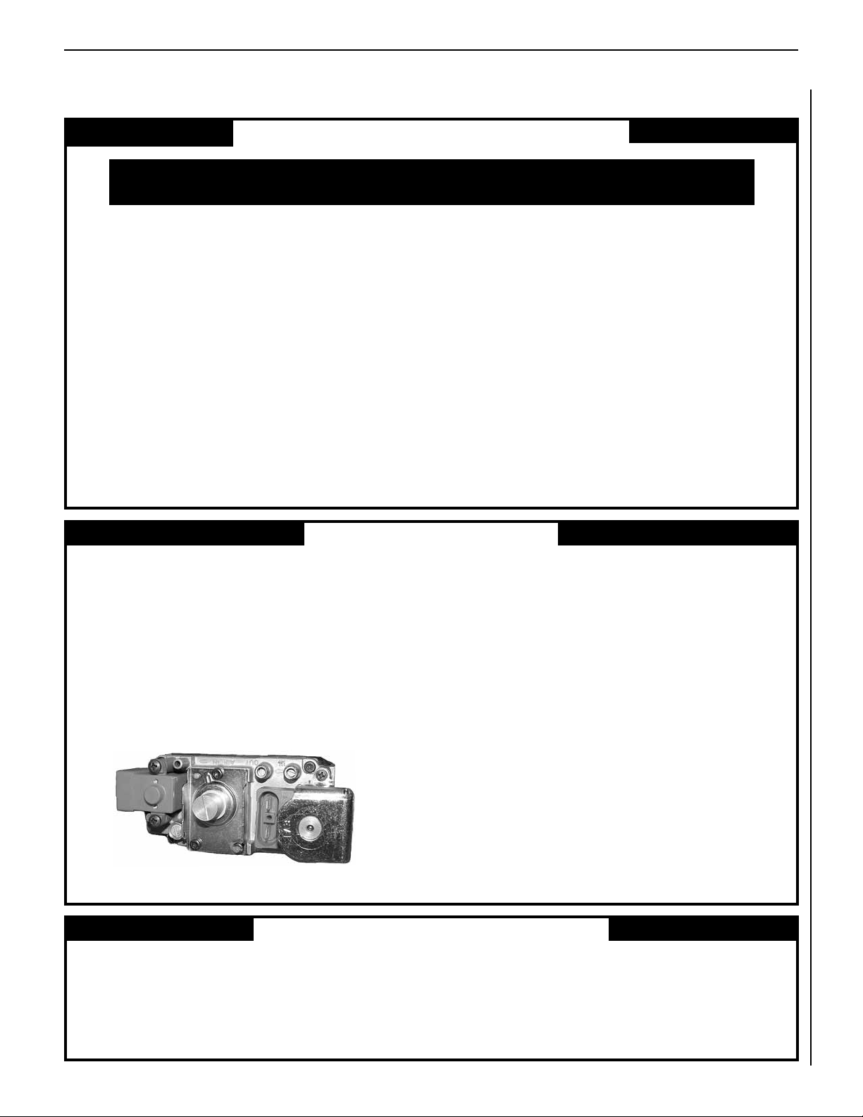
Remote Control System (Standard) H0249 RCL
Standard Remote Control System
(Model RCL)
The Model RCL (Standard) Remote Control
System, features a simplistic on/off control
function for the replace. This model includes
a hand-held transmitter, a remote receiver with
wall-mount coverplate and all hardware required
to install the unit. The remote receiver can be
wall or hearth mounted.
The transmitter has ON and OFF functions that
are activated by pressing either button on the
face of the transmitter. When a button on the
transmitter is pressed, a signal light illuminates
briefly to verify that a signal has been sent.
The Model RCL is designed to operate with all
millivolt ignition systems, as well as electronic
ignition systems. It may be installed with use
for either natural or propane gas appliances.
The RCL offers ease of installation and allows
you to execute on-off commands to the replace
effortlessly with one simple motion.
The Model RCL comes complete with detailed
operating instructions.
Pine Cones and
Wood Bits 91L05 FPCK
Twelve Piece Ember Kit
A twelve piece ember kit (model FPCK) has been
developed to provide a means of enhancing
the already impressive log presentation of this
replace. This kit contains three (3) ceramic
ber pine cones and nine (9) ceramic ber
debris wood bits. All twelve elements will not
be consumed in the flames and may be placed
within the presentation area (without impinging
any of the lofting flames) to add realism and
enhance the rustic look and appeal of the re.
Decorative Volcanic Stone 80L42 FDVS
Bag of Glowing Embers 88L53 FGE
Decorative Volcanic Stone
The decorative volcanic stone, Model FDVS, can
be used to enhance the look of your appliance.
Spread the decorative volcanic stone evenly
around the bottom of the rebox.
Bag of Glowing Embers
Replacement ember materials are available
for use with these appliances. Order a bag of
Glowing Embers, Model FGE to replace ember
materials as part of the periodic maintenance
of the appliance.
H5794 36LBFB
H5795 36LBFB-BB
H5796 36LBFB-BS
H5797 42LBFB
H5798 42LBFB-BB
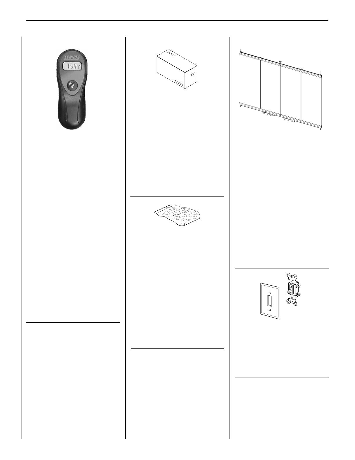
Bi-Fold Doors H5799 42LBFB-BS
Bi-Fold Doors
Your appliance can be tted with beautiful bi-fold
doors. Model 36/42LBFB doors are available
for use with these appliances. Doors are easily
tted to the replace opening. Model 36/42LBFB
doors come with standard black nish. Model
36/42LBFB-BB doors have a beautiful bright
brass nish. Model 36/42LBFB-BS doors are
made of brushed stainless steel.
Note: To ensure warranty and to prevent a
potential fire hazard, do not use any other
doors on these appliances.
ON/OFF Wall Switch Kit 85L87 FWSK
ON/OFF Wall Switch Kit
18
The ON/OFF wall switch kit must be used to
control the operation of the replace burner.
Install the ON/OFF wall switch in a convenient
location near the replace.
NOTE: DIAGRAMS & ILLUSTRATIONS ARE NOT TO SCALE.
Page 19

LENNOX CRESTLINE™ SERIES B-VENT GAS FIREPLACES • 36"/42" LSBV MODELS • CARE AND OPERATION INSTRUCTIONS
ACCESSORY COMPONENTS
Outside Combustion Air Kits
(with duct) 81L87 FOAK-4
(without duct) 81L88 FOAK-LD
Arch Screen Door H1960
H1961
Decorative Arch Screen Door
This attractive screen door is east to install
and enhances the appearance of the appliance.
H5800 LDGHK36
Hood Kit H5801 LDGHK42
Hood Kit
This hood is designed to be tted to the face of
the appliance. In addition to providing an aesthetically pleasing appearance to your appliance
installation, the hood reduces heat effects to
decorative mantles and nish materials located
above the replace opening.
Touch-Up Paint Kit (Black) 90L73 FTPK-B
Touch-Up Paint Kit
Repair of minor scratches and discoloration
of the appliance black painted surfaces may
be accomplished with the touch-up paint kit.
NOTE: DIAGRAMS & ILLUSTRATIONS ARE NOT TO SCALE.
19
Page 20

LENNOX CRESTLINE™ SERIES B-VENT GAS FIREPLACES • 36"/42" LSBV MODELS • CARE AND OPERATION INSTRUCTIONS
REPLACEMENT PARTS LIST
LSBV-3628 LSBV-4228
No. DESCRIPTION Part No. Qty. Part No. Qty.
1. Gas Fireplace Assembly – – – –
2. Firescreen H3820 2 H3827 2
3. Rod, Screen H3815 2 H3828 2
4. Refractory, Side (RH) H3816 1 H3816 1
Refractory, Side (RH) Herringbone H3821 1 H3829 1
5. Refractory, Side (LH) H3817 1 H3817 1
Refractroy, Side (LH) Herringbone H3822 1 H3830 1
6. Refractory, Rear H3819 1 H3824 1
Refractory, Rear, Herringbone H3823 1 H3831 1
7. Refractory Access Panel H4952 1 H4952 1
8. Refractory, Base (Left) H4948 1 H4949 1
9. Refractory, Base (Right) H4950 1 H4951 1
10. Log Set, Complete H5803 1 H5803 1
11. Burner Assembly - Complete H5804 1 H5804 1
12. Damper Switch H2327 1 H2327 1
13. Limit Switch H1614 1 H1614 1
14. Appliance Mounted On/Off Switch 80L41 1 80L41 1
GAS CONTROLS — MILLIVOLT
Natural Propane
No. DESCRIPTION Part No. Qty. Part No. Qty.
16. Gas Valve - SIT H1658 1 H1659 1
17. Piezo Ignitor - SIT 10K86 1 10K86 1
18. Orice, Main H5805 1 39L66 1
19. Pilot Assembly 62L12 1 62L13 1
GAS CONTROLS — ELECTRONIC
Natural
No. DESCRIPTION Part No. Qty.
26. Gas Valve - SIT 18L44 1
27. Pilot Assembly - SIT H2298 1
28. Orice, Main H5805 1
29. Transformer And Spark Module 78H35 1
30. Ignition Module H1167 1
20
NOTE: DIAGRAMS & ILLUSTRATIONS ARE NOT TO SCALE.
Page 21

LENNOX CRESTLINE™ SERIES B-VENT GAS FIREPLACES • 36"/42" LSBV MODELS • CARE AND OPERATION INSTRUCTIONS
REPLACEMENT PARTS
13
12
2
3
1
14
4
6
5
11
18
MILLIVOLT
19
10
16
17
28
ELECTRONIC
NOTE: DIAGRAMS & ILLUSTRATIONS ARE NOT TO SCALE.
29
8
7
9
26
30
27
21
Page 22

Notes
LENNOX CRESTLINE™ SERIES B-VENT GAS FIREPLACES • 36"/42" LSBV MODELS • CARE AND OPERATION INSTRUCTIONS
22
Page 23

Notes
LENNOX CRESTLINE™ SERIES B-VENT GAS FIREPLACES • 36"/42" LSBV MODELS • CARE AND OPERATION INSTRUCTIONS
23
Page 24

Notes
LENNOX CRESTLINE™ SERIES B-VENT GAS FIREPLACES • 36"/42" LSBV MODELS • CARE AND OPERATION INSTRUCTIONS
Lennox Hearth Products reserves the right to make changes at any time, without notice, in design,
materials, specications, and prices, and also to discontinue colors, styles, and products.
Consult your local distributor for replace code information.
Printed in U.S.A. © 2007 by Lennox Hearth Products
24
P/N 875035M REV. D 07/2010
1508 Elm Hill Pike, Suite 108 • Nashville, TN 37210
 Loading...