


WARNINGS
• Hot! Do not touch! The glass and
surfaces of this appliance will be hot
during operation and will retain heat
for a whileaftershutting off theappliance. Severe burns may result.
• Carefully supervise children in the
same room as appliance.
• If small children are present in the home, it is
recommended thatthis appliance be fitted with
a screen door or screen panel kit. See
for ordering information.
Page 17
HOMEOWNER'S CARE AND
OPERATION INSTRUCTIONS
MERIT® SERIES
42" B-VENTED GAS APPLIANCES
P/N 875,034M REV. A 02/2007
MODELS
Millivolt Models Electronic Models
LMBV-42RMN LMBV-42REN
LMBV-42RMP
RETAIN THESE INSTRUCTIONS
FOR FUTURE REFERENCE
WH Report No. 3106807
WARNING: IF THE INFORMATION IN THIS MANUAL
IS NOT FOLLOWED EXACTLY, A FIRE OR EXPLOSION MAY RESULT CAUSING PROPERTY DAMAGE, PERSONAL INJURY OR LOSS OF LIFE.
FOR YOUR SAFETY: Do not store or use gasoline
or other flammable vapors or liquids in the vicinity of this or any other appliance.
FOR YOUR SAFETY: What to do if you smell gas:
• DO NOT light any appliance.
• DO NOT touch any electrical switches.
• DO NOT use any phone in your building.
• Immediately call your gas supplier from a
neighbor’s phone.
Follow your gas suppliers instructions.
• If your gas supplier cannot be reached, call the
fire department.
Installation and service must be performed by a
qualified installer, service agency or the gas
supplier.
NOTE: DIAGRAMS & ILLUSTRATIONS NOT TO SCALE.
AVERTISSEMENT: ASSUREZ-VOUS DE BIEN SUIVRE
LES INSTRUCTIONS DONNÉ DANS CETTE NOTICE POUR
RÉDUIRE AU MINIMUM LE RISQUE D'INCENDIE OU
POUR ÉVITER TOUT DOMMAGE MATÉRIEL, TOUTE
BLESSURE OU LA MORT.
POUR VOTRE SÉCURITÉ: Ne pas entreposer ni utiliser
d'essence ni d'autre vapeurs ou liquides inflammables
dans le voisinage de cet appareil ou de tout autre
appareil.
POUR VOTRE SÉCURITÉ: Que faire si vous sentez une
odiur de gaz:
• Ne pas tenter d'allumer d'appareil.
• Ne touchez à aucun interrupteur. Ne pas vous servir
des téléphones se trouvant dans le batiment où
vous vous trouvez.
• Evacuez la piéce, le bâtiment ou la zone.
• Appelez immédiatement votre fournisseur de gaz
depuis un voisin. Suivez les instructions du
fournisseur.
• Si vous ne pouvez rejoindre le fournisseur de gaz,
appelez le service dos incendies.
L'installation et service doit être exécuté par un qualifié
installeur, agence de service ou le fournisseur de gaz.
1

CONGRATULATIONS!
GENERAL INFORMATION
In selecting this LENNOX B-vented gas appliance you have chosen the finest and most
dependable fireplace to be found anywhere. A beautiful, prestigious, alternative to a
wood burning fireplace. Welcome to a Family of tens of thousands of satisfied LENNOX
Fireplace Owners.
Please read and carefully follow all of the instructions found in this manual. Please pay
special attention to the safety instructions provided in this manual. The Homeowner's
Care and Operation Instructions included here will assure that you have many years of
dependable and enjoyable service from your LENNOX product.
TABLE OF CONTENTS
Introduction ..................................... page 2
General Information......................... page 2
Operation/Care of Your Appliance.... page 3
Damper & Outside Air Controls ....... page 4
Manual Limit Switch ........................ page 5
Maintenance .................................... page 6
Millivolt Appliance Checkout............ page 6
Electronic Appliance Checkout......... page 6
Maintenance Schedule..................... page 7
Log and Rockwool Placement ......... page 8
Wiring Diagrams.............................. page 9
Lighting Instructions – Millivolt ....... page 10
Lighting Instructions – Electronic .... page 12
Troubleshooting Guide – Millivolt ..... page 14
Troubleshooting Guide – Electronic .. page 15
Warranty.......................................... page 16
Product Reference Information ....... page 16
Replacement Parts .......................... page 16
Accessory Components ................... page 17
Replacement Parts List ..................... page 18
These appliances comply with National Safety
Standards and are tested and listed by Warnock Hersey (Report No. 3106807) to ANSI
Z21.50 - latest edition (in Canada, CSA 2.22 latest edition), and CAN/CGA-2.17-M91 in both
USA and Canada, as vented gas fireplaces.
Installation must conform to local codes. In
the absence of local codes, installation must
comply with the current National Fuel Gas
Code, ANSI Z223.1 (NFPA 54). (In Canada, the
current CAN/CGA B149 installation code.) Electrical wiring must comply with local codes. In
the absence of local codes, installation must
be in accordance with the National Electrical
Code, NFPA 70 - (latest edition). (In Canada,
the current CSA C22.1 Canadian Electric Code.)
DO NOT ATTEMPT TO ALTER OR MODIFY
THE CONSTRUCTION OF THE APPLIANCE OR
ITS COMPONENTS. ANY MODIFICATION OR
ALTERATION MAY VOID THE WARRANTY,
CERTIFICATION AND LISTINGS OF THIS UNIT.
WARNING: IMPROPER INSTALLATION,
ADJUSTMENT, ALTERATION, SERVICE
OR MAINTENANCE CAN CAUSE INJURY
OR PROPERTY DAMAGE. REFER TO
THIS MANUAL. FOR ASSISTANCE OR
ADDITIONAL INFORMATION CONSULT
INTRODUCTION
The millivolt appliances are designed to operate on either natural or propane gas. A millivolt
gas control valve with piezo ignition system
provides safe, efficient operation.
A QUALIFIED INSTALLER, SERVICE
AGENCY OR THE GAS SUPPLIER.
WARNING: ELECTRONIC MODELS OF
THESE APPLIANCES ARE EQUIPPED
WITH A THREE-PRONG (GROUNDING)
The electronic appliances are designed to operate on either natural or propane gas. An
electronic intermittent ignition system provides safe, efficient operation. External electrical power is required to operate these units.
PLUG UTILIZED IN CONNECTING THE
ELECTRONIC COMPONENTS TO THE
JUNCTION BOX IN THE LOWER COMPARTMENT. THIS GROUNDING PLUG
PROVIDES PROTECTION AGAINST
SHOCK HAZARD AND SHOULD BE
PLUGGED DIRECTLY INTO THE PROPERLY GROUNDED THREE-PRONG RECEPTACLE. DO NOT CUT OR REMOVE
THE GROUNDING PRONG FROM THE
PLUG.
Note: Installation and repair should be per-
formed by a qualified service person. The appliance should be inspected annually by a qualified professional service technician. More frequent inspections and cleanings may be required due to excessive lint from carpeting,
bedding material, etc. It is imperative that the
control compartment, burners and circulating
air passage ways of the appliance be kept clean.
S'assurer que le brùleur et le compartiment
des commandes sont propres. Voir les instructions d'installation et d'utilisation qui
accompagnent l'apareil.
Provide adequate clearances around air openings and adequate accessibility clearance for
service and proper operation. Never obstruct
the front openings of the appliance.
Due to high temperatures the appliance should
be located out of traffic and away from furniture and draperies. Locate furniture and window coverings accordingly.
WARNING: THESE FIREPLACES ARE
VENTED DECORATIVE GAS APPLIANCES. DO NOT BURN WOOD OR OTHER
MATERIAL IN THESE APPLIANCES.
These appliances are designed to operate on
natural or propane gas only. The use of
other fuels or combination of fuels will degrade the performance of this system and
may be dangerous.
Input of appliance is 30,000 BTU/HR.
Gas Orifice
Type Size Elevation
Natural
Propane
Nominal operating pressures for the manifold
side of the gas control system are; 3.5 inches
water column (0.87 kPa) for natural gas models and 10 inches water column (2.49 kPa) for
propane gas models.
#37
(0.104)
(0.065)
0 - 4500'
(0 - 1370 m)
0 - 4500'
(0 - 1370 m)
2
NOTE: DIAGRAMS & ILLUSTRATIONS NOT TO SCALE.

Refractory
Access Panel
SIT Valve Shown
Gas Controls
on Valve
Piezo
Ignitor
Do not use these appliances if any part has
been under water. Immediately call a qualified,
professional service technician to inspect the
appliance and to replace any parts of the
control system and any gas control which
have been under water.
Ne pas se servir de cet appareil s'il a été
plongé dans l'eau, complètement ou en partie.
Appeler un technicien qualifié pour inspecter
l'appareil et remplacer toute partie du système
de contrôle et toute commande qui ont été
plongés dans l'leau.
Test gage connections are provided on the
front of the millivolt gas control valve (identified E for the inlet and A for the manifold side.
See Figure 2
is provided at the inlet and manifold side of
the electronic gas control valve (
Minimum inlet gas pressure to the appliance is
4.5 inches water column (1.24 kPa) for natural
gas and 11 inches water column (2.74 kPa) for
propane for the purpose of input adjustment.
Maximum inlet gas supply pressure to the
appliance is 10.5 inches water column (2.62
kPa) for natural gas and 13.0 inches water
column (3.23 kPa) for propane.
The appliance must be isolated from the gas
supply piping system (by closing its individual manual shut-off valve) during any
pressure testing of the gas supply piping
system at test pressures equal to or less than
¹⁄₂ psig (3.5 kPa).
The appliance and its individual shut-off valve
must be disconnected from the gas supply
piping system during any pressure testing of
that system at pressures in excess of ¹⁄₂ psig
(3.5 kPa).
These appliances must not be connected to a
chimney or flue serving a separate solid fuel
burning appliance.
). A ¹⁄₈" NPT test gage connection
See Figure 3
WARNING: FAILURE TO COMPLY
WITH THE INSTALLATION AND OPERATING INSTRUCTIONS PROVIDED IN
THIS DOCUMENT WILL RESULT IN AN
IMPROPERLY INSTALLED AND OPERATING APPLIANCE, VOIDING ITS
WARRANTY. ANY CHANGE TO THIS
APPLIANCE AND/OR ITS OPERATING
CONTROLS IS DANGEROUS. IMPROPER INSTALLATION OR USE OF
THIS APPLIANCE CAN CAUSE SERIOUS INJURY OR DEATH FORM FIRE,
BURNS, EXPLOSION OR CARBON
MONOXIDE POISONING.
Carbon Monoxide Poisoning: Early signs of
carbon monoxide poisoning are similar to
the flu with headaches, dizziness and/or nausea. If you have these signs, obtain fresh air
immediately. Turn off the gas supply to the
appliance and have it serviced by a qualified
professional, as it may not be operating
correctly.
WARNING: B-VENT APPLIANCES ARE
NOT DESIGNED TO OPERATE IN NEGATIVELY PRESSURED ENVIRONMENTS
(PRESSURE WITHIN THE HOME IS LESS
THAN PRESSURES OUTSIDE). SIGNIFICANT NEGATIVELY PRESSURED ENVIRONMENTS CAUSED BY WEATHER,
HOME DESIGN, OR OTHER DEVICES
MAY IMPACT THE OPERATION OF THESE
).
APPLIANCES. NEGATIVE PRESSURES
MAY RESULT IN POOR FLAME APPEARANCE, SOOTING, DAMAGE TO PROPERTY AND/OR SEVERE PERSONAL INJURY. DO NOT OPERATE THESE APPLIANCES IN NEGATIVELY PRESSURED
ENVIRONMENTS.
WARNING: CHILDREN AND ADULTS
SHOULD BE ALERTED TO THE HAZARDS OF HIGH SURFACE TEMPERATURES. USE CAUTION AROUND THE
APPLIANCE TO AVOID BURNS OR
CLOTHING IGNITION. YOUNG CHILDREN SHOULD BE CAREFULLY SUPERVISED WHEN THEY ARE IN THE SAME
ROOM AS THE APPLIANCE.
WARNING: DO NOT PLACE CLOTHING
OR OTHER FLAMMABLE MATERIALS
ON OR NEAR THIS APPLIANCE.
AVERTISSEMENT: SURVEILLER LES
ENFANTS. GARDER LES VÊTEMENTS,
LES MEUBLES, L'ESSENCE OU AUTRES
LIQUIDES À VAPEUR INFLAMMABLES
LOIN DE L'APPAREIL.
OPERATION AND CARE OF YOUR
APPLIANCE
1. Appliance operation may be controlled
through a remotely located optional wall switch.
Separate switches may provide independent
control for the remote controlled fireplace operation (optional equipment).
NOTE: DIAGRAMS & ILLUSTRATIONS NOT TO SCALE.
In lieu of remote or remote wall switch operation, the appliance must be operated directly
through the controls located on the front of the
valve located within the control compartment
under the removable refractory access panel,
Figure 1.
Figure 1
Operation of millivolt and electronic gas control systems are different. Before lighting and
operating your appliance determine if you have
a millivolt or electronic appliance.
Figure 1
ment below the lower refractory panel. Millivolt appliances will be fitted with one of the two
gas control valves shown in
ances with electronic systems will be fitted
with the electronic valve shown in
Familiarize yourself with the differing controls
for the valve your appliance uses.
To light millivolt appliances refer to the detailed lighting instructions found in both English and French on
instructions respectively. Millivolt and elec-
tronic appliance lighting instructions may
also be found on the pull out labels attached
to the gas control valve located within the
gas control compartment. Refer to
to locate the appropriate location for the spark
ignitor used with your appliance.
If your appliance is equipped with an optional
remote wall switch or remote control kit the
appliance main burner may be turned on and
off with the wall switch or remote control. If
the appliance is not equipped with a wall or
remote control, the main burner must be turned
off and on with the gas control knob. Turn the
knob counter-clockwise from the PILOT position to ON to light the main burner, and clockwise from ON to PILOT to turn off the main
burner.
to access the gas control compart-
Figure 2.
pages 10 and 11
Refer to
Appli-
Figure 3.
of these
Figure 2
3

CAUTION: DO NOT ATTEMPT TO TOUCH THE
EA
TPTH TP TH
DOORS WITH YOUR HANDS WHILE THE FIREPLACE IS IN USE. ALWAYS USE DOOR
HANDLES. DOORS WILL BECOME VERY HOT
WHEN FIREPLACE IS IN USE.
P
I
L
O
T
SIT Millivolt Valve
Figure 2
Manifold Presssure Port
CONTROL
ON
IG
N
IT
E
OFF
ON/OFF Switch
I
I
S
P
Electronic
Gas Control
Valve
Inlet
Pressure
Port
Honeywell Electronic
Figure 3
To light electronic appliances refer to the detailed lighting instructions found in both English and French on
instructions respectively. Millivolt and elec-
tronic appliance lighting instructions may also
be found on the pull out labels attached to the
gas control valve located within the gas control compartment.
If your appliance is equipped with an optional
remote wall switch or remote control kit the
appliance main burner may be turner on and off
with the wall switch or remote control. If the
appliance is not equipped with a wall switch or
remote control, the main burner must be turned
off and on with the gas control switch. Toggle
the switch from ON to OFF to operate the main
burner from ON to OFF.
2. When lit for the first time, this appliance will
emit a slight odor for an hour or two. This is
due to the “burn-in” of internal paints and
lubricants used in the manufacturing process.
Gas Valve
pages 12 and 13
of these
F
F
O
P
I
L
it
O
T
O
N
Piezo
Ignitor
Gas Control
Knob
3. Keep lower control compartment clean by
vacuuming or brushing at least twice a year.
More frequent cleaning may be required due to
excessive lint from carpeting, bedding materials, etc. It is important that control compartments, burners and circulating air passageways of the appliance be kept clean and clear of
obstruction of ventilating and combustion air.
4. Always turn off gas to the pilot (millivolt
appliances) before cleaning. Before re-lighting, refer to the lighting instructions in this
manual. Instructions are also found on a pullout panel located on the floor of the appliance.
5. Always keep the appliance area clear and
free from combustible materials, gasoline and
other flammable liquids.
6. Remember, Millivolt appliances have a continuous burning pilot flame. Exercise caution
when using products with combustible vapors.
7. Clean the optional glass doors only when
necessary. Wipe surface with clean, dampened, soft cloth. Follow with dry, soft towel as
desired. Take care not to scratch the glass
surface.
WARNING: REPLACE ANY SAFETY
SCREEN OR GUARD REMOVED FOR
SERVICING AN APPLIANCE PRIOR TO
OPERATING THE APPLIANCE.
WARNING: DO NOT USE ABRASIVE
CLEANERS. NEVER CLEAN THE GLASS
WHEN IT IS HOT.
CAUTION: NEVER OPERATE THIS APPLIANCE
WITH A BROKEN OR DAMAGED GLASS DOOR.
REMOVE OR REPLACE ANY BROKEN GLASS
DOOR BEFORE OPERATING.
WARNING: DO NOT ATTEMPT TO REPAIR BROKEN GLASS COMPONENTS.
REPLACE ANY BROKEN DOORS ONLY
WITH COMPLETE DOOR KITS, OBTAINED FROM LENNOX. REMOVE ANY
BROKEN GLASS PIECES BY VACUUMING THEM OUT COMPLETELY.
WARNING: DO NOT STRIKE OR SLAM
SHUT OPTIONAL GLASS DOORS.
WARNING: FIREPLACES EQUIPPED
WITH OPTIONAL ACCESSORY DOORS
SHOULD BE OPERATED ONLY WITH THE
DOORS FULLY OPEN OR FULLY CLOSED
(
FIGURE 4
). THIS APPLIANCE MAY
ONLY BE FITTED WITH DOORS CERTIFIED FOR USE WITH THE APPLIANCE.
AVERTISSEMENT: POUR UTILISATION
UNIQUEMENT AVEC LES PORTES EN
VERRE CERTIFIÊES AVEC L'APPAREIL.
Fully Open or
Fully Closed
Figure 4
DAMPER AND COMBUSTION AIR CONTROLS
This appliance is fitted with a manually controlled vent damper. The vent damper should
be closed when the appliance is not in use to
prevent cold air from entering the home through
the venting system. The damper is controlled
through the use of a control lever located
within the appliance opening at the top center
in front of the firebox lintel (
see Figure 5
).
4
NOTE: DIAGRAMS & ILLUSTRATIONS NOT TO SCALE.

The control lever snaps into place at either
extreme of its range of motion. When locked
in position all the way to the right, the damper
is open. When locked in position all the way to
the left, the damper is closed.
The damper lever actuates a switch, (see wiring diagram) which will prevent the appliance
main burner from lighting unless the damper
is locked open. The appliance flue damper
must always remain open when operating.
WARNING: DAMPER MUST BE IN OPEN
POSITION WHEN APPLIANCE MAIN
BURNER IS OPERATING.
AVERTISSEMENT: LE REGISTRE DOIT
ÊTRE EN POSITION OUVERTE LORSQUE
LE OU LES BRULEURS PRINCIPAUX DE
L'APPEREIL FONCTIONNMENT.
WARNING: DO NOT OPERATE THE COMBUSTION AIR ACTUATOR UNLESS A
COMPLETE OUTSIDE AIR VENT SYSTEM HAS BEEN INSTALLED WITH YOUR
APPLIANCE.
Combustion Air
Actuator
Remove Locking Screw
and “Pop” Actuator to the
Left Before Initial Use
Pull the actuator forward to open the combustion air door, and push it back to close. To "lock"
the combustion air door closed, ensure the
actuator is pushed all the way back, then push
the end of the actuators to the right until the
step in the actuator moves behind the appliance
front face within the slotted opening.
MANUALLY-RESET BLOCKED FLUE SAFETY
SWITCH
This appliance is equipped with a manuallyreset blocked flue safety switch. Refer to
Figure 7
operation, the flame goes out (independently
of the burner on/off wall switch), it may be due
to the operation of this safety limit switch.
First allow the appliance to cool, then reset
the safety switch by pushing the red reset
button on the back of the switch.
CAUTION: THE ELECTRONIC APPLIANCE
SHOULD BE TURNED OFF BEFORE REMOVING THE LIMIT SWITCH.
for its location. If during appliance
Damper
Closed
Damper
Open
Lintel
Outside Air
Actuator
Figure 5
Many appliances are equipped when installed
with an outside (make-up) air vent system that
is designed to provide the appliance with outside make-up air for combustion when in
operation. The actuator for the outside air
system is standard on all appliances but must
not be operated if the complete system is not
installed. Refer to
plete outside air vent system is installed, the
installer will remove the actuator locking screw.
If your screw is not removed and you have
reason to believe that you have a complete
outside air system, contact your distributor to
have your appliance inspected for the presence of the complete system.
DO NOT assume that you have this system in
place because you have an actuating lever
present on your appliance front face.
Figure 6
. When the com-
Pull Forward to Open,
Push Back to Close
Figure 6
To provide outside combustion air to your
appliance while it is in operation, locate the
combustion air actuator along the right side of
the appliance opening (
To operate, push the end of the actuator to the
left as shown in
its "locked" position.
Figure 6
Figure 5
, until it "pops" free of
).
Manual
Reset
Limit
Switch
To access the safety limit switch reset button,
remove the screen rod and screen from the
right side of the fireplace. Unscrew two screws
and remove the limit switch with low voltage
wires attached. Push the reset button, then
reinstall the limit switch. Reinstall the screen
and rod. At this time turn the electronic
appliance back on.
The appliance should then relight and remain
lit. If this does not occur, turn off the appli-
ance and call a qualified service technician.
Limit Switch Screws
Screen
Rod
Screen
Figure 7
NOTE: DIAGRAMS & ILLUSTRATIONS NOT TO SCALE.
Lintel Extension Right Side Refractory Panel
5
Maintenance
The appliance and venting system should be
thoroughly inspected before initial use and at
least annually by a qualified service technician. Proper maintenance and use will require
more frequent, less extensive inspections and
servicing by the homeowner.
Generally, annual inspections should be performed by a qualified service technician. More
frequent periodic inspections and cleanings
should be performed by the homeowner. Any
discrepancies discovered by the homeowner
should result in a call to a qualified service
technician to effect the repair or correction.
Refer to the maintenance schedule for maintenance tasks, procedures, periodicity and by
whom they should be performed.
IMPORTANT: TURN OFF GAS AND ANY
ELECTRICAL POWER BEFORE SERVICING
THE APPLIANCE.
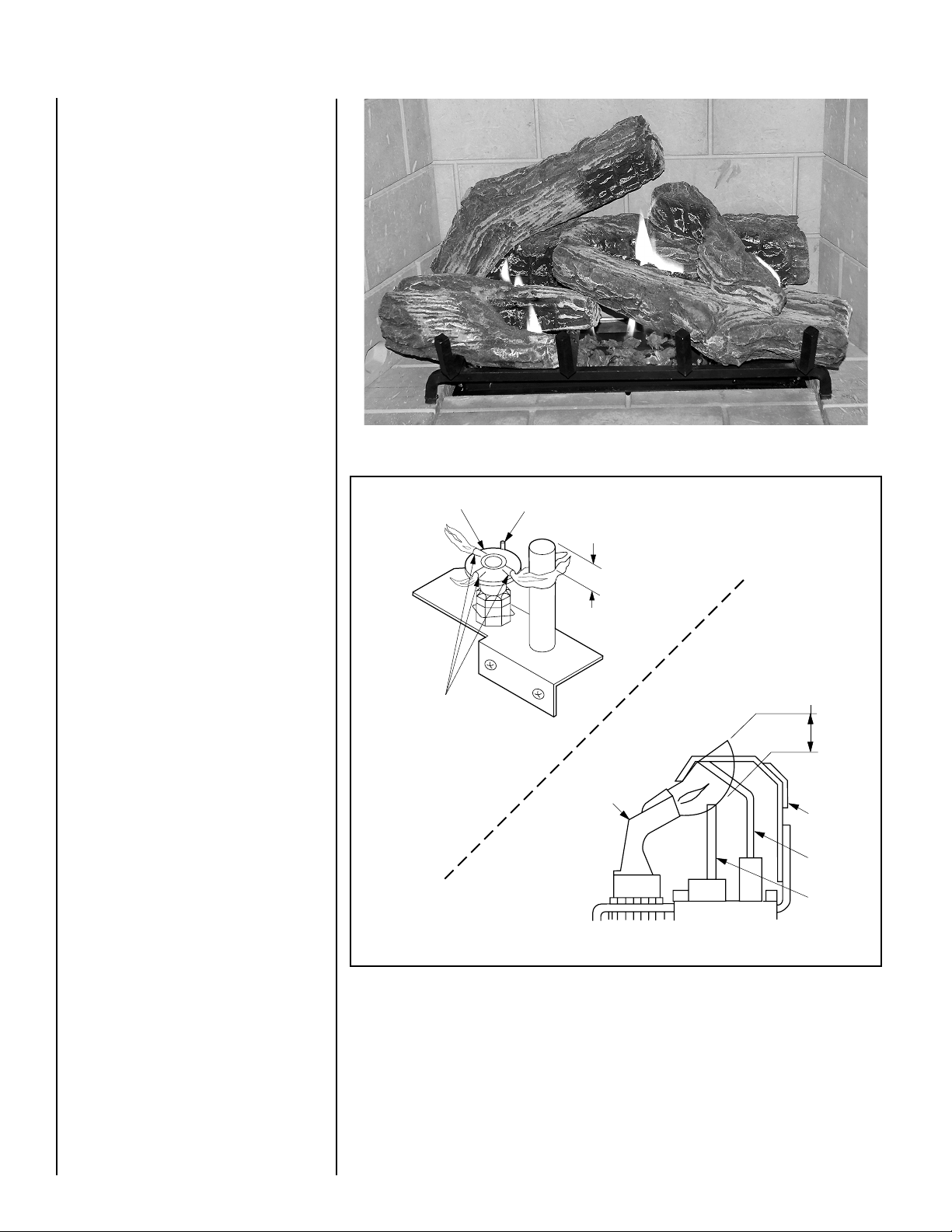
Millivolt Appliance Checkout
The pilot flame should be steady, not lifting or
floating. Flame should be blue in color with
traces of orange at the outer edge.
Figure 8
MILLIVOLT
Hood
Ignitor Rod
³⁄₈" Min
(9 mm)
The top ³⁄₈" (9 mm) at the pilot generator
(thermopile) should be engulfed in the pilot
flame. The flame should project 1" (25 mm)
beyond the hood at all three ports
(Figure 9 ).
Electronic Appliance Checkout
Light the burner, refer to the Lightilng Instructions in this manual. Ensure the ignitor lights
the pilot. The pilot flame should engulf the
flame rod as shown in
Figure 9.
With proper care and maintenance, your appliance will provide many years of enjoyment.
If you should experience any problem, first
refer to the trouble shooting guide in this
manual. If problem persists, contact your
Superior distributor.
Figure 9
Pilot
Nozzels
ELECTRONIC
Pilot
Nozzle
Proper Flame
Adjustment
3/8 To 1/2 Inch
(9 mm to 13 mm)
Ground
Electrode
Flame Rod
Hot Surface
Igniter
6
NOTE: DIAGRAMS & ILLUSTRATIONS NOT TO SCALE.
 Loading...