

Page 1
INSTALLER: Leave this manual with the appliance.
CONSUMER: Retain this manual for future reference.
INSTALLATEUR: Laissez cette notice avec l'appareil.
CONSOMMATEUR: Conservez cette notice pour consultation ultérieure.
WARNING: If the information in these instructions is
causing property damage, personal injury or death.
- Ne pas entreposer ni utilizer d’essence ni d’autres
de cet appareil ou de tout autre appareil.
- QUE FAIRE SI VOUS SENTEZ UNE ODEUR DE GAZ:
• Ne pas tenter d’allumer d’appareil.
• Ne touchez à aucan interrupteur. Ne pas vous servir
des téléphones se trouvant dans le bâtiment où vous
trouvez.
• Appelez immédiatement votre fournisseur de
gaz depuis un voisin. Suivez les instructions du
fournisseur.
• Si vous ne pouvez rejoindre le fournisseur de gaz,
appelez le service des incindies.
- L’installation et l’entretien doivent être assurés par un
le fournisseur de gaz.
AVERTISSEMENT: Assurez-vous de bien suivre les
instructions données dans cette notice pour réduire
au minimum le risque d’incindie ou d’explosion ou
pour éviter tout dommage matériel, toute blessure
ou la mort.
This appliance may be installed in an aftermarket permanently located, manufactured home (USA only) or mobile
home, where not prohibited by local codes. This appliance is only for use with the type of gas indicated on the rating
WARNING
AVERTISSEMENT
UNE SURFACE VITRÉE CHAUDE PEUT
CAUSER DES BRÛLURES.
LAISSER REFROIDIR LA SURFACE
VITRÉE AVANT D'Y TOUCHER.
NE PERMETTEZ JAMAIS À UN ENFANT
DE TOUCHER LA SURFACE VITRÉE.
HOT GLASS WILL
CAUSE BURNS.
DO NOT TOUCH GLASS
UNTIL COOLED.
NEVER ALLOW CHILDREN TO
TOUCH GLASS.
and liquids in the vicinity of this or any other appliance.
- WHAT TO DO IF YOU SMELL GAS
• Do not try to light any appliance.
• Do not touch any electrical switch; do not use any
phone in your building.
• Immediately call your gas supplier from a neighbor’s
phone. Follow the gas supplier’s instructions.
•
department.
installer, service agency or the gas supplier.
P/N 875033M Rev. C 07/2010
This manual is one of a set of two supporting this product.
Refer to P/N 850040M for Installation Instructions.
This manual is available in French. Order P/N 506223-24.
Ce manuel est disponible en francais. Simplement en faire
la demande numéro de la pièce 506223-24.
WH Report No. 3106807
CARE AND OPERATION INSTRUCTIONS
B-Vent Gas Fireplaces
36" LMBV Models
MODELS
Millivolt Models
LMBV-36RMN
LMBV-36RMP
Electronic Models
LMBV-36REN
Page 2
LENNOX MERIT® SERIES B-VENT GAS FIREPLACES • 36" LMBV MODELS • CARE AND OPERATION INSTRUCTIONS
CONGRATULATIONS!
In selecting this LENNOX B-vented gas appliance, you have chosen one of the finest
and most dependable fireplaces available. This gas fireplaces is a beautiful, prestigious
alternative to a wood burning fireplace. Welcome to a family of tens of thousands of
satisfied LENNOX fireplace owners.
Please read and carefully follow all of the instructions found in this manual. Please
pay special attention to the safety instructions provided in this manual. The Care and
Operation Instructions included herein will help to ensure many years of dependable and
enjoyable service from your LENNOX product.
TABLE OF CONTENTS
Introduction ......................................page 2
General Information ..........................page 2
Operation/Care of Your Appliance .....page 3
Damper & Outside Air Controls .........page 4
Manual Limit Switch .........................page 5
Maintenance ......................................page 6
Millivolt Appliance Checkout .............page 6
Attaching "Safety-in-Operation"
Warnings ............................ page 6
Electronic Appliance Checkout ..........page 7
Maintenance Schedule ......................page 8
Log and Rockwool Placement ...........page 9
Wiring Diagrams ...............................page 10
Lighting Instructions – Millivolt ........page 11
Lighting Instructions – Electronic .....page 13
Troubleshooting Guide – Millivolt......page 15
Troubleshooting Guide – Electronic ..page 16
Warranty ...........................................page 17
Product Reference Information .........page 17
Replacement Parts ............................page 17
Accessory Components ....................page 18
Replacement Parts List .....................page 19
GENERAL INFORMATION
Note: Installation and repair should be performed by a qualified service person. The
appliance should be inspected annually by a
qualified professional service technician. More
frequent inspections and cleanings may be
required due to excessive lint from carpeting,
bedding material, etc. It is imperative that the
control compartment, burners and circulating
air passage ways of the appliance be kept clean.
S'assurer que le brùleur et le compartiment des
commandes sont propres. Voir les instructions
d'installation et d'utilisation qui accompagnent
l'apareil.
Provide adequate clearances around air openings and adequate accessibility clearance for
service and proper operation. Never obstruct
the front openings of the appliance.
Due to high temperatures the appliance should
be located out of traffic and away from furniture
and draperies. Locate furniture and window
coverings accordingly.
WARNING
Improper installation, adjustment,
INTRODUCTION
The millivolt appliances are designed to operate
on either natural or propane gas. A millivolt gas
control valve with piezo ignition system provides
safe, efficient operation.
The electronic appliances are designed to
operate on either natural or propane gas. An
electronic intermittent ignition system provides
safe, efficient operation. External electrical
power is required to operate these units.
These appliances comply with National Safety
Standards and are tested and listed by Warnock
Hersey (Report No. 3106807) to ANSI Z21.50
- latest edition (in Canada, CSA 2.22 - latest
edition), and CAN/CGA-2.17-M91 in both USA
and Canada, as vented gas fireplaces.
Installation must conform to local codes. In
the absence of local codes, installation must
comply with the current National Fuel Gas Code,
ANSI Z223.1 (NFPA 54). (In Canada, the current
CAN/CGA B149 installation code.) Electrical
wiring must comply with local codes. In the
absence of local codes, installation must be in
accordance with the National Electrical Code,
NFPA 70 - (latest edition). (In Canada, the current
2
CSA C22.1 Canadian Electric Code.)
alteration, service or maintenance
can cause injury or property
damage. Refer to this manual. For
assistance or additional information consult a qualied installer,
service agency or the gas supplier.
WARNING
B-Vent appliances are not designed
to operate in negatively pressured
environments (pressure within
the home is less than pressures
outside). Signicant negatively
pressured environments caused
by weather, home design, or
other devices may impact the
operation of these appliances.
Negative pressures may result in
poor ame appearance, sooting,
damage to property and/or severe
personal injury. Do not operate
these appliances in negatively
pressured environments.
NOTE: DIAGRAMS & ILLUSTRATIONS ARE NOT TO SCALE.
WARNING: THESE FIREPLACES ARE
VENTED DECORATIVE GAS APPLIANCES.
DO NOT BURN WOOD OR OTHER MATERIAL IN THESE APPLIANCES.
These appliances are designed to operate on
natural or propane gas only. The use of other
fuels or combination of fuels will degrade the
performance of this system and may be dangerous.
DO NOT ATTEMPT TO ALTER OR MODIFY
THE CONSTRUCTION OF THE APPLIANCE OR
ITS COMPONENTS. ANY MODIFICATION OR
ALTERATION MAY VOID THE WARRANTY,
CERTIFICATION AND LISTINGS OF THIS UNIT.
Input of appliance is 24,000 BTU/HR.
Gas Orifice
Type Size Elevation
0 - 4500'
Natural
(0 - 1370 m)
0 - 4500'
Propane
(0 - 1370 m)
Nominal operating pressures for the manifold
side of the gas control system are; 3.5 inches
water column (0.87 kPa) for natural gas models
and 10 inches water column (2.49 kPa) for
propane gas models.
Test gage connections are provided on the front
of the millivolt gas control valve (identified E
for the inlet and A for the manifold side, see
Figure 2 ). A 1/8" NPT test gage connection
is provided at the inlet and manifold side of
the electronic gas control valve (Figure 3 ).
Minimum inlet gas pressure to the appliance is
4.5 inches water column (1.24 kPa) for natural
gas and 11 inches water column (2.74 kPa) for
propane for the purpose of input adjustment.
Maximum inlet gas supply pressure to the ap-
pliance is 10.5 inches water column (2.62 kPa)
for natural gas and 13.0 inches water column
(3.23 kPa) for propane.
The appliance must be isolated from the gas
supply piping system (by closing its individual
manual shut-off valve) during any pressure
testing of the gas supply piping system at
test pressures equal to or less than 1/2 psig
(3.5 kPa).
The appliance and its individual shut-off valve
must be disconnected from the gas supply
piping system during any pressure testing of
that system at pressures in excess of 1/2 psig
(3.5 kPa).
These appliances must not be connected to a
chimney or flue serving a separate solid fuel
burning appliance.
#42
(.0935)
(.058)
Page 3
LENNOX MERIT® SERIES B-VENT GAS FIREPLACES • 36" LMBV MODELS • CARE AND OPERATION INSTRUCTIONS
Refractory
Access Panel
SIT Valve Shown
Gas Controls
on Valve
Piezo
Ignitor
WARNING: FAILURE TO COMPLY WITH
THE INSTALLATION AND OPERATING
INSTRUCTIONS PROVIDED IN THIS DOCUMENT WILL RESULT IN AN IMPROPERLY
INSTALLED AND OPERATING APPLIANCE,
VOIDING ITS WARRANTY. ANY CHANGE TO
THIS APPLIANCE AND/OR ITS OPERATING
CONTROLS IS DANGEROUS. IMPROPER
INSTALLATION OR USE OF THIS APPLIANCE CAN CAUSE SERIOUS INJURY OR
DEATH FORM FIRE, BURNS, EXPLOSION
OR CARBON MONOXIDE POISONING.
Carbon Monoxide Poisoning: Early signs
of carbon monoxide poisoning are similar
to the flu with headaches, dizziness and/
or nausea. If you have these signs, obtain
fresh air immediately. Turn off the gas supply to the appliance and have it serviced by
a qualified professional, as it may not be
operating correctly.
WARNING: ELECTRONIC MODELS OF
THESE APPLIANCES ARE EQUIPPED
WITH A THREE-PRONG (GROUNDING)
PLUG UTILIZED IN CONNECTING THE
ELECTRONIC COMPONENTS TO THE
JUNCTION BOX IN THE LOWER COMPARTMENT. THIS GROUNDING PLUG PROVIDES
PROTECTION AGAINST SHOCK HAZARD
AND SHOULD BE PLUGGED DIRECTLY
INTO THE PROPERLY GROUNDED THREEPRONG RECEPTACLE. DO NOT CUT OR
REMOVE THE GROUNDING PRONG FROM
THE PLUG.
WARNING: CHILDREN AND ADULTS
SHOULD BE ALERTED TO THE HAZARDS
OF HIGH SURFACE TEMPERATURES. USE
CAUTION AROUND THE APPLIANCE TO
AVOID BURNS OR CLOTHING IGNITION.
YOUNG CHILDREN SHOULD BE CAREFULLY SUPERVISED WHEN THEY ARE IN
THE SAME ROOM AS THE APPLIANCE.
Les enfants et les adultes devraient être
infor-més des dangers que posent les
températures de surface élevées et se
tenir à distance an d’éviter des brûlures
ou que leurs vêtements ne s’enamment.
WARNING: DO NOT PLACE CLOTHING
OR OTHER FLAMMABLE MATERIALS ON
OR NEAR THIS APPLIANCE.
AVERTISSEMENT: GARDER LES VÊTEMENTS, LES MEUBLES, L'ESSENCE OU
AUTRES LIQUIDES À VAPEUR INFLAMMABLES LOIN DE L'APPAREIL.
Do not use these appliances if any part has
been under water. Immediately call a qualified,
professional service technician to inspect the
appliance and to replace any parts of the control
system and any gas control which have been
under water.
Ne pas se servir de cet appareil s'il a été
plongé dans l'eau, complètement ou en
partie. Appeler un technicien qualifié pour
inspecter l'appareil et remplacer toute partie
du système de contrôle et toute commande
qui ont été plongés dans l'leau.
OPERATION AND CARE OF YOUR
APPLIANCE
WARNING
Young children should be carefully
supervised when they are in the
same room as the appliance. Toddlers, young children and others
may be susceptible to accidental
contact burns. A physical barrier
is recommended if there are at
risk individuals in the house. To
restrict access to a replace or
stove, install an adjustable safety
gate to keep toddlers, young children and other at risk individuals
out of the room and away from hot
surfaces.
AVERTISSEMENT
Les jeunes enfants devraient être
surveillés étroitement lorsqu’ils
se trouvent dans la même pièce
que l’appareil. Les tout petits,
les jeunes enfants ou les adultes
peuvent subir des brûlures s’ils
viennent en contact avec la surface chaude. Il est recommandé
d’installer une barrière physique
si des personnes à risques habitent la maison. Pour empêcher
l’accès à un foyer ou à un poêle,
installez une barrière de sécurité;
cette mesure empêchera les tout
petits, les jeunes enfants et toute
autre personne à risque d’avoir
accès à la pièce et aux surfaces
chaudes.
1. Appliance operation may be controlled
through a remotely located optional wall switch.
Separate switches may provide independent
control for the remote controlled fireplace
operation (optional equipment).
NOTE: DIAGRAMS & ILLUSTRATIONS ARE NOT TO SCALE.
In lieu of remote or remote wall switch operation,
the appliance must be operated directly through
the controls located on the front of the valve
located within the control compartment under
the removable refractory access panel, Figure 1.
Figure 1
Operation of millivolt and electronic gas
control systems are different. Before lighting
and operating your appliance determine if you
have a millivolt or electronic appliance. Refer
to Figure 1 to access the gas control compart-
ment below the lower refractory panel. Millivolt
appliances will be fitted with one of the two gas
control valves shown in Figure 2. Appliances
with electronic systems will be fitted with the
electronic valve shown in Figure 3. Familiarize
yourself with the differing controls for the valve
your appliance uses.
To light millivolt appliances refer to the detailed
lighting instructions found in both English and
French on pages 11 and 12 of these instructions respectively. Millivolt and electronic
appliance lighting instructions may also be
found on the pull out labels attached to the gas
control valve located within the gas control
compartment. Refer to Figure 2 to locate the
appropriate location for the spark ignitor used
with your appliance.
If your appliance is equipped with an optional
remote wall switch or remote control kit the
appliance main burner may be turned on and
off with the wall switch or remote control. If the
appliance is not equipped with a wall or remote
control, the main burner must be turned off and
on with the gas control knob. Turn the knob
counter-clockwise from the PILOT position
to ON to light the main burner, and clockwise
from ON to PILOT to turn off the main burner.
3
Page 4
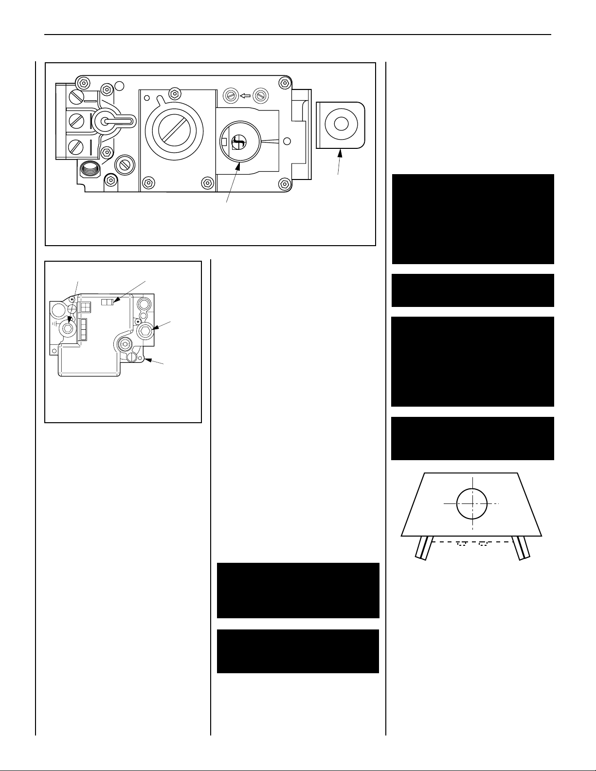
Figure 2
Fully Open or
Fully Closed
E A
TPTH TP TH
P
I
L
O
T
P
I
L
O
T
O
N
it
O
F
F
SIT Millivolt Valve
Gas Control
Knob
Piezo
Ignitor
Manifold Pressure Port
Figure 3
To light electronic appliances refer to the detailed
lighting instructions found in both English and
French on pages 13 and 14 of these instructions
respectively. Millivolt and electronic appliance
lighting instructions may also be found on the
pull out labels attached to the gas control valve
located within the gas control compartment.
If your appliance is equipped with an optional
remote wall switch or remote control kit the
appliance main burner may be turner on and off
with the wall switch or remote control. If the
appliance is not equipped with a wall switch or
remote control, the main burner must be turned
off and on with the gas control switch. Toggle
the switch from ON to OFF to operate the main
burner from ON to OFF.
2. When lit for the first time, this appliance will
emit a slight odor for an hour or two. This is due
to the “burn-in” of internal paints and lubricants
used in the manufacturing process.
4
LENNOX MERIT® SERIES B-VENT GAS FIREPLACES • 36" LMBV MODELS • CARE AND OPERATION INSTRUCTIONS
CAUTION: DO NOT ATTEMPT TO TOUCH THE
DOORS WITH YOUR HANDS WHILE THE
FIREPLACE IS IN USE. ALWAYS USE DOOR
HANDLES. DOORS WILL BECOME VERY HOT
WHEN FIREPLACE IS IN USE.
CAUTION: NEVER OPERATE THIS APPLIANCE
WITH A BROKEN OR DAMAGED GLASS DOOR.
REMOVE OR REPLACE ANY BROKEN GLASS
DOOR COMPONENT BEFORE OPERATION.
WARNING: DO NOT ATTEMPT TO REPAIR BROKEN GLASS COMPONENTS.
REPLACE ANY BROKEN DOORS ONLY
WITH COMPLETE DOOR KITS, OBTAINED
FROM LENNOX. REMOVE ANY BROKEN
GLASS PIECES BY VACUUMING THEM
OUT COMPLETELY.
3. Keep lower control compartment clean by
ON/OFF Switch
CONTROL
OFF
ON
IGNITER
Honeywell Electronic
IN
PSI
Inlet
Pressure
Port
Electronic
Gas Control
Valve
vacuuming or brushing at least twice a year.
More frequent cleaning may be required due to
excessive lint from carpeting, bedding materials,
etc. It is important that control compartments,
burners and circulating air passageways of the
appliance be kept clean and clear of obstruction
of ventilating and combustion air.
4. Always turn off gas to the pilot (millivolt
appliances) before cleaning. Before re-lighting,
refer to the lighting instructions in this manual.
Instructions are also found on a pull-out panel
located on the floor of the appliance.
WARNING: DO NOT STRIKE OR SLAM
SHUT OPTIONAL GLASS DOORS.
WARNING: FIREPLACES EQUIPPED
WITH OPTIONAL ACCESSORY DOORS
SHOULD BE OPERATED ONLY WITH THE
DOORS FULLY OPEN OR FULLY CLOSED
(FIGURE 4 ). THIS APPLIANCE MAY ONLY
BE FITTED WITH DOORS CERTIFIED FOR
USE WITH THE APPLIANCE.
Gas Valve
5. Always keep the appliance area clear and
free from combustible materials, gasoline and
other flammable liquids.
AVERTISSEMENT: POUR UTILISATION
UNIQUEMENT AVEC LES PORTES EN
VERRE CERTIFIÊES AVEC L'APPAREIL.
6. Remember, Millivolt appliances have a
continuous burning pilot flame. Exercise caution when using products with combustible
vapors.
7. Clean the optional glass doors only when
necessary. Wipe surface with clean, dampened,
soft cloth. Follow with dry, soft towel as desired.
Take care not to scratch the glass surface.
WARNING: REPLACE ANY SAFETY
SCREEN OR GUARD REMOVED FOR
Figure 4
SERVICING AN APPLIANCE PRIOR TO
OPERATING THE APPLIANCE.
WARNING: DO NOT USE ABRASIVE
CLEANERS. NEVER CLEAN THE GLASS
WHEN IT IS HOT.
NOTE: DIAGRAMS & ILLUSTRATIONS ARE NOT TO SCALE.
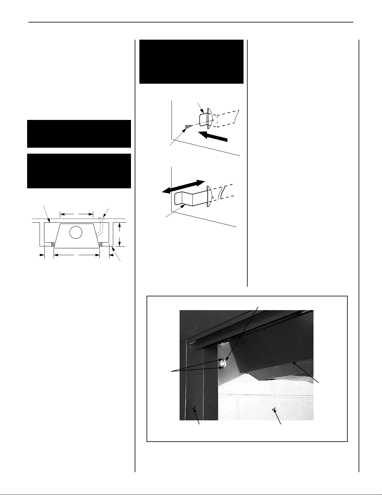
DAMPER AND COMBUSTION AIR CONTROLS
This appliance is fitted with a manually controlled
vent damper. The vent damper should be closed
when the appliance is not in use to prevent cold
air from entering the home through the venting
system. The damper is controlled through the
use of a control lever located within the appliance opening at the top center in front of the
firebox lintel (see Figure 5 ).
Page 5
LENNOX MERIT® SERIES B-VENT GAS FIREPLACES • 36" LMBV MODELS • CARE AND OPERATION INSTRUCTIONS
C
A
G
Inside Chase
Back Wall of Chase/Enclosure
Including Finishing Materials
if any
Rough Framing Face (Unfinished Shown)
H
H
Optional FOAK
Combustion Air Kit
Limit
Switch
Screws
Manual Reset Limit Switch
Lintel
Extention
Fireplace Front Left Side Refractory Panel
The control lever snaps into place at either
extreme of its range of motion. When locked
in position all the way to the right, the damper
is open. When locked in position all the way to
the left, the damper is closed.
The damper lever actuates a switch, (see wiring
diagram) which will prevent the appliance main
burner from lighting unless the damper is locked
open. The appliance flue damper must always
remain open when operating.
WARNING: DAMPER MUST BE IN OPEN
POSITION WHEN APPLIANCE MAIN
BURNER IS OPERATING.
AVERTISSEMENT: LE REGISTRE DOIT
ÊTRE EN POSITION OUVERTE LORSQUE
LE OU LES BRULEURS PRINCIPAUX DE
L'APPEREIL FONCTIONNMENT.
Figure 5
WARNING: DO NOT OPERATE THE
COMBUSTION AIR ACTUATOR UNLESS
A COMPLETE OUTSIDE AIR VENT SYSTEM HAS BEEN INSTALLED WITH YOUR
APPLIANCE.
Combustion Air
Actuator
Remove Locking Screw
and “Pop” Actuator to the
Left Before Initial Use
Pull Forward to Open,
Push Back to Close
Figure 6
To provide outside combustion air to your
appliance while it is in operation, locate the
combustion air actuator along the right side
of the appliance opening (Figure 5 ).
To operate, push the end of the actuator to the
left as shown in Figure 6, until it "pops" free of
its "locked" position. Pull the actuator forward
to open the combustion air door, and push it
back to close. To "lock" the combustion air
door closed, ensure the actuator is pushed all
the way back, then push the end of the actuators to the right until the step in the actuator
moves behind the appliance front face within
the slotted opening.
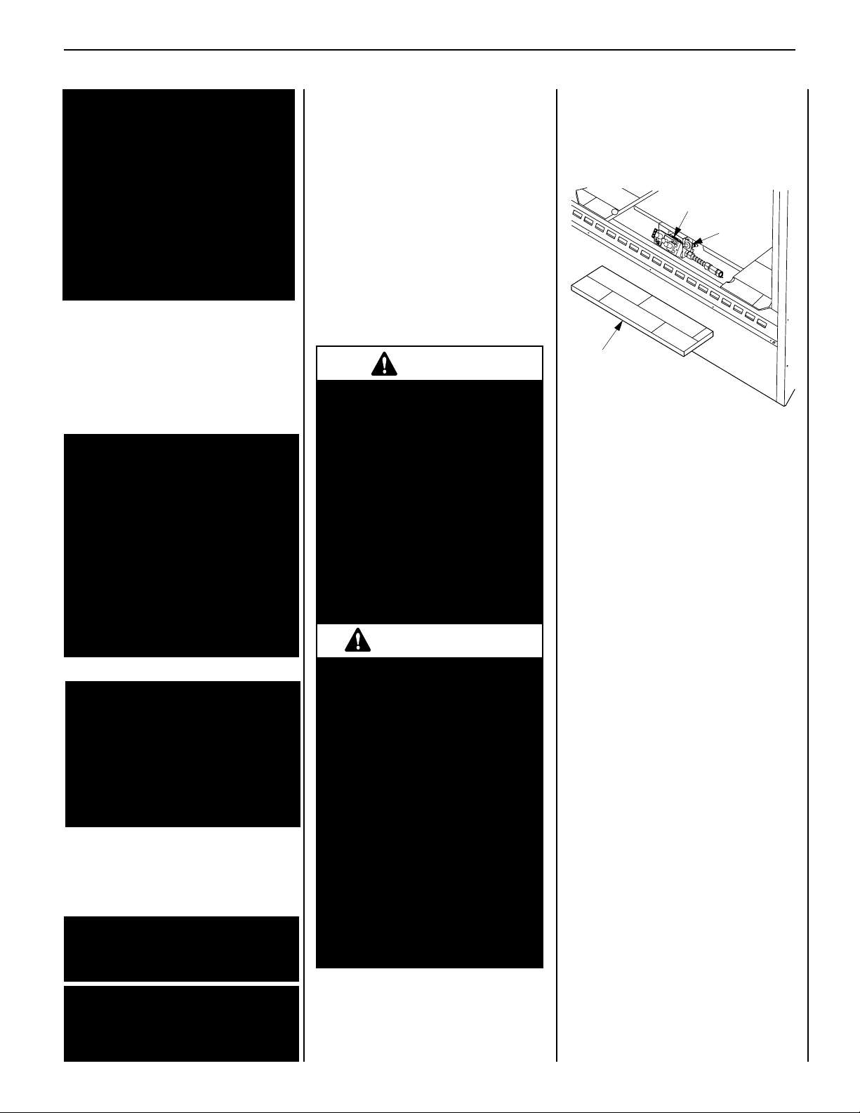
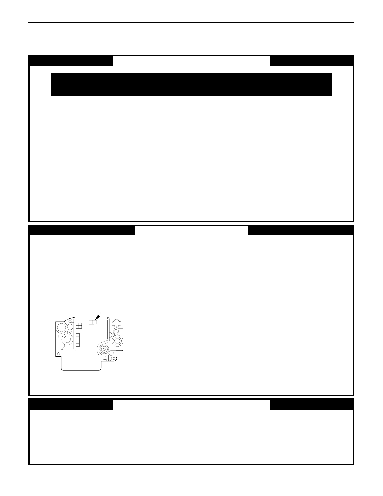
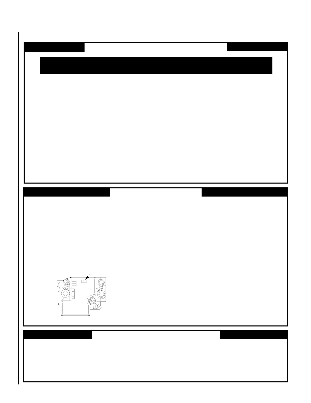
MANUALLY-RESET BLOCKED FLUE SAFETY
SWITCH
This appliance is equipped with a manually-reset
blocked flue safety switch. Refer to Figure 7
for its location. If during appliance operation,
the flame goes out (independently of the burner
on/off wall switch), it may be due to the operation of this safety limit switch. First allow the
appliance to cool, then reset the safety switch
by pushing the red reset button on the back
of the switch.
CAUTION: THE ELECTRONIC APPLIANCE
SHOULD BE TURNED OFF BEFORE REMOVING
THE LIMIT SWITCH.
To access the safety limit switch reset button,
remove the two screws. Pull out limit switch
with low voltage wires attached, push the reset
button, then reinstall the limit switch. At this
time turn the electronic appliance back on.
The appliance should then relight and remain
lit. If this does not occur, turn off the appliance
and call a qualified service technician.
Many appliances are equipped when installed
with an outside (make-up) air vent system that
is designed to provide the appliance with outside
make-up air for combustion when in operation.
The actuator for the outside air system is standard on all appliances but must not be operated
if the complete system is not installed. Refer to
Figure 6. When the complete outside air vent
system is installed, the installer will remove the
actuator locking screw.
If your screw is not removed and you have
reason to believe that you have a complete
outside air system, contact your distributor to
have your appliance inspected for the presence
of the complete system. DO NOT assume that
you have this system in place because you have
an actuating lever present on your appliance
front face.
Figure 7
5
NOTE: DIAGRAMS & ILLUSTRATIONS ARE NOT TO SCALE.
Page 6
LENNOX MERIT® SERIES B-VENT GAS FIREPLACES • 36" LMBV MODELS • CARE AND OPERATION INSTRUCTIONS
Un foyer chaud peut causer
de graves brûlures
Ne laissez jamais un enfant
toucher à la vitre ou à toutes
autres parties du foyer
AVERTISSEMENT
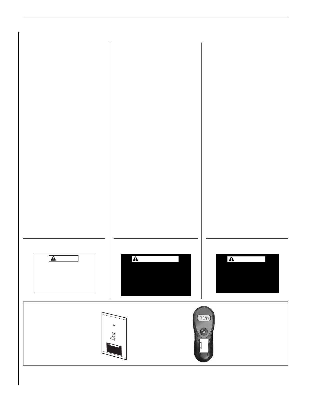
HOMEOWNER’S INSTRUCTIONS - ATTACHING "SAFETY-IN-OPERATION" WARNINGS
ATTACHING SAFETY IN OPERATION WARNINGS
Your fireplace has been furnished with safety instruction labels that are to be affixed to the operation and
control point of the fireplace. A safety instruction
label should be affixed to the wall switch plate where
the fireplace is turned on and off (See Figure A) and
if used on the remote control handheld transmitter
(Figure B). The warnings should already have been
put in place when the fireplace initial set-up was
completed. If they are not affixed at these spots,
locate the multi-lingual adhesive labels provided
with these instructions and proceed as follows:
1. Locate the wall switch that controls the fireplace
(verify the switch operates the fireplace by turn-
ing it on and off). Clean the wall switch plate
thoroughly to remove any dust and oils. Affix the
label to the surface of the plate of the wall switch
that controls the fireplace (Figure A). Choose
the language primarily spoken in the home.
2. If a remote control is used to control the fireplace,
locate the transmitter and clean it thoroughly
to remove any dust and oils. Affix the label to
the surface of handheld transmitter (Figure B).
Choose the language primarily spoken in the
home.
3. If you are unable to locate the labels, please call
Lennox Hearth Products or your nearest Lennox
Hearth Products dealer to receive additional
safety instruction labels free of charge.
Cat. No. H8024 Replacement Label Kit
LENNOX HEARTH PRODUCTS
1-800-9-LENNOX
Note: English is red text on clear label. French and
Spanish are white text on black label.
APPOSITION DES MISES EN GARDE RELATIVES
À LA SÉCURITÉ D’UTILISATION
Votre foyer a été livré avec des étiquettes de sécurité qui
doivent être collées à côté des dispositifs de contrôle
du foyer. Une étiquette de sécurité devrait être collée
sur la plaque de l’interrupteur contrôlant l’allumage du
foyer (voir Figure A) et, le cas échéant, sur le boîtier
de la télécommande (Figure B). Les mises en garde
auraient dû être collées au moment de l’installation
initiale du foyer. Si ce n’est pas le cas, prenez les
étiquettes adhésives multilingues fournies avec ces
instructions et procédez comme suit:
1. Repérez l’interrupteur qui contrôle le foyer (vérifiez
que l’interrupteur contrôle le fonctionnement du
foyer en le faisant basculer de Marche à Arrêt, et
vice-versa). Nettoyez soigneusement la plaque
murale de l’interrupteur pour éliminer la poussière
et les traces de graisse ou d’huile. Collez l’étiquette
sur la surface de la plaque de l’interrupteur mural
qui contrôle le foyer (Figure A). Choisissez la langue
qui est principalement parlée dans la résidence
du propriétaire.
2. Si une télécommande est utilisée pour contrôler
le foyer, nettoyez la soigneusement pour éliminer
la poussière et les traces de graisse ou d’huile.
Collez l’étiquette sur le boîtier de la télécommande
(Figure B). Choisissez la langue qui est principale-
ment parlée dans la résidence du propriétaire.
3. Si vous ne trouvez pas les étiquettes, veuillez
appeler Lennox Hearth Products ou votre distributeur Lennox Hearth Products local pour recevoir
gratuitement des étiquettes supplémentaires.
Étiquettes de remplacement, n° cat. H8024
LENNOX HEARTH PRODUCTS
1-800-9-LENNOX
Remarque : Le texte anglais est rouge sur un support
transparent. Le texte français et espagnol est blanc
sur un support noir.
COLOCACIÓN DE ADVERTENCIAS DE SEGURIDAD
EN OPERACIÓN
Su chimenea incluye etiquetas de instrucciones de
seguridad que deben colocarse en el punto de operación
y control de la chimenea. Se debe colocar una etiqueta
de instrucciones de seguridad en la placa del interruptor
de pared desde el cual se enciende y se apaga la
chimenea (ver la Figura A) y en el transmisor de control
remoto (Figura B) si se usa. Las advertencias ya deben
haberse colocado cuando se completó la instalación
inicial de la chimenea. Si no están colocadas en estos
lugares, encuentre las etiquetas adhesivas multilingües
proporcionadas con estas instrucciones y prosiga de
la siguiente manera:
1. Identifique el interruptor de pared que controla
la chimenea (verifique que el interruptor opera la
chimenea encendiéndola y apagándola). Limpie
bien la placa del interruptor de pared para quitar el
polvo y aceite. Pegue la etiqueta en la superficie de
la placa del interruptor que controla la chimenea
(Figura A). Seleccione el idioma que más se habla
en la casa.
2. Si se usa un control remoto para controlar la
chimenea, encuentre el transmisor y límpielo bien
para quitar el polvo y aceite. Pegue la etiqueta en la
superficie del transmisor (Figura B). Seleccione el
idioma que más se habla en la casa.
3. Si no puede encontrar las etiquetas, sírvase llamar a
Lennox Hearth Products o al distribuidor de Lennox
Hearth Products más cercano para recibir etiquetas
de instrucciones de seguridad adicionales gratuitas.
Juego de etiquetas de repuesto - Nº de cat. H8024
LENNOX HEARTH PRODUCTS
1-800-9-LENNOX
Nota: La etiqueta en inglés es transparente con texto
rojo. Las etiquetas en francés y español son negras
con texto blanco.
SAFETY LABEL DIAGRAMS
WARNING
Hot Fireplace Will Cause
Severe Burns
Never Allow Children to
Touch Glass or other Fireplace Parts
Figure A
DIAGRAMMES DES ÉTIQUETTES DE SÉCURITÉ DIAGRAMAS DE ETIQUETAS DE SEGURIDAD
AVERTISSEMENT
Un foyer chaud peut causer
de graves brûlures
Ne laissez jamais un enfant
toucher à la vitre ou à toutes
autres parties du foyer
Figure B
WARNING
Hot Fireplace Will Cause
Severe Burns
Never Allow Children to
Touch Glass or other Fire-
La chimenea caliente
causará quemaduras graves
Nunca permita que los niños
toquen el vidrio ni otras
partes de la chimenea
place Parts
ADVERTENCIA
6
NOTE: DIAGRAMS & ILLUSTRATIONS ARE NOT TO SCALE.
Page 7
LENNOX MERIT® SERIES B-VENT GAS FIREPLACES • 36" LMBV MODELS • CARE AND OPERATION INSTRUCTIONS
3/8" Min
(9 mm)
Hood
Pilot
Nozzels
Ignitor Rod
Proper Flame
Adjustment
Hot Surface
Igniter
Flame Rod
Ground
Electrode
3/8 To 1/2 Inch
(9 mm to 13 mm)
Pilot
Nozzle
MILLIVOLT
ELECTRONIC
Maintenance
The appliance and venting system should be
thoroughly inspected before initial use and at
least annually by a qualified service technician.
Proper maintenance and use will require more
frequent, less extensive inspections and servicing by the homeowner.
Generally, annual inspections should be performed by a qualified service technician. More
frequent periodic inspections and cleanings
should be performed by the homeowner. Any
discrepancies discovered by the homeowner
should result in a call to a qualified service
technician to effect the repair or correction.
Refer to the maintenance schedule for maintenance tasks, procedures, periodicity and by
whom they should be performed.
IMPORTANT: TURN OFF GAS AND ANY
ELECTRICAL POWER BEFORE SERVICING
THE APPLIANCE.
Figure 8
Millivolt Appliance Checkout
The pilot flame should be steady, not lifting
or floating. Flame should be blue in color with
traces of orange at the outer edge.
The top 3/8" (9 mm) at the pilot generator (thermopile) should be engulfed in the pilot ame.
The ame should project 1" (25 mm) beyond
the hood at all three ports (Figure 9 ).
Electronic Appliance Checkout
Light the burner, refer to the Lightilng Instructions in this manual. Ensure the ignitor lights
the pilot. The pilot flame should engulf the
flame rod as shown in Figure 9.
With proper care and maintenance, your appliance will provide many years of enjoyment. If
you should experience any problem, first refer
to the trouble shooting guide in this manual.
If problem persists, contact your Lennox
distributor.
Figure 9
NOTE: DIAGRAMS & ILLUSTRATIONS ARE NOT TO SCALE.
7
Page 8
LENNOX MERIT® SERIES B-VENT GAS FIREPLACES • 36" LMBV MODELS • CARE AND OPERATION INSTRUCTIONS
Maintenance Schedule
Annually (Before the onset of the Burning Season)
Maintenance Task Accomplishing Person Procedure
Inspecting/Cleaning Burner, Logs
and Controls
Check Flame Patterns and Flame Height
Inspecting/Cleaning Pilot and Burner
Checking Vent System
Appliance Checkout
Replacing Rockwool Ember Materials
Qualified Service Technician
Qualified Service Technician
Qualified Service Technician
Qualified Service Technician
Qualified Service Technician
Homeowner/Qualified Services Technician
Inspect valve and ensure it is properly operating. Check piping for leaks. Vacuum
the control compartment, fireplace logs and
burner area.
Refer to Figure 8 and verify the flame pattern
and height displayed by the appliance conforms
to the picture. Flames must not impinge on
the logs.
Refer to Figure 9. Remove any surface build-up
on pilot and burner assembly. Wipe the pilot
nozzles, ignitor/flame rod and hood. Ensure
the pilot flame engulfs the flame sensor as
shown.
Inspect the vent system at the top and at the
base (within the rebox) for signs of blockage
or obstruction. Look for any signs of dislocation of the vent components.
Perform the appropriate appliance checkout
procedure detailed in this manual.
Remove old ember materials and vacuum the
screened rockwool placement area. Place new
rockwool as described in this document.
Periodically (After the Burning Season)
Maintenance Task Accomplishing Person Procedure
Cleaning Firebox Interior
Homeowner
Carefully remove logs, Rockwool and volcanic
stone if used. Vacuum out interior of the firebox.
Clean firebox walls and log grate. Replace
logs, Rockwool and volcanic stone as detailed
in this manual.
Check Flame Patterns and Flame Height
Homeowner
Refer to Figure 8 and verify the flame pattern
and height displayed by the appliance conforms
to the picture. Flames must not impinge on
the logs.
Checking Vent System
Homeowner
Inspect the vent system at the top and at the
base (within the rebox) for signs of blockage
or obstruction. Look for any signs of dislocation
of the vent components.
Cleaning Optional Glass Doors
Homeowner
Clean as necessary following the directions
provided in this manual. DO NOT TOUCH OR
ATTEMPT TO CLEAN DOORS WHILE THEY
ARE HOT.
8
NOTE: DIAGRAMS & ILLUSTRATIONS ARE NOT TO SCALE.
Page 9
LENNOX MERIT® SERIES B-VENT GAS FIREPLACES • 36" LMBV MODELS • CARE AND OPERATION INSTRUCTIONS
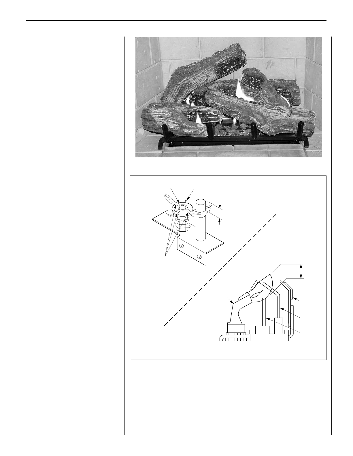
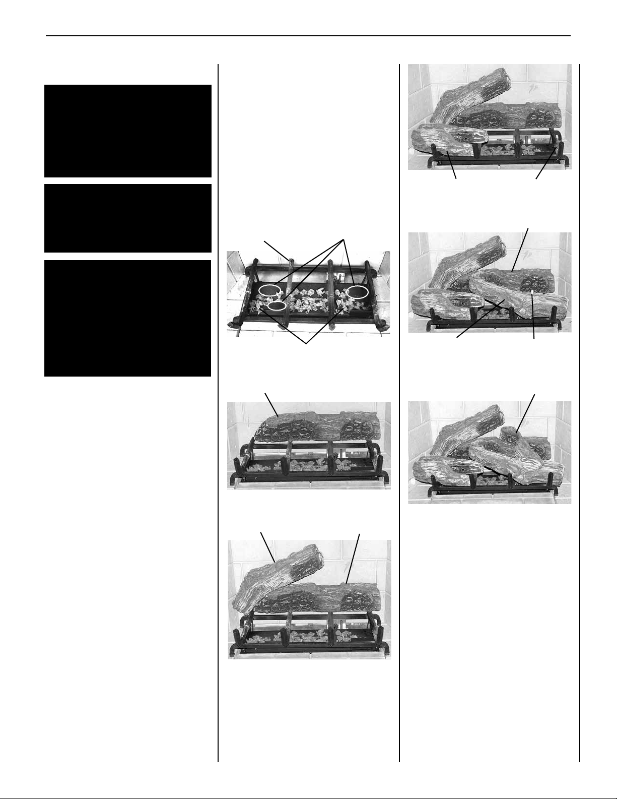
Logs and Rockwool Placement
WARNING: LOGS GET VERY HOT AND
WILL REMAIN HOT UP TO ONE HOUR
AFTER GAS SUPPLY IS TURNED OFF.
HANDLE ONLY WHEN LOGS ARE COOL.
TURN OFF ALL ELECTRICITY TO THE APPLIANCE BEFORE YOU INSTALL GRATE
AND LOGS.
WARNING: THIS APPLIANCE IS NOT
MEANT TO BURN WOOD. ANY ATTEMPT
TO DO SO COULD CAUSE IRREPARABLE
DAMAGE TO YOUR APPLIANCE AND
PROVE HAZARDOUS TO YOUR SAFETY.
WARNING: THE SIZE AND POSITION ON
THE LOG SET WAS ENGINEERED TO GIVE
YOUR APPLIANCE A SAFE, RELIABLE
AND ATTRACTIVE FLAME PATTERN.
ANY ATTEMPT TO USE A DIFFERENT
LOG SET IN THE FIREPLACE WILL VOID
THE WARRANTY AND WILL RESULT IN
INCOMPLETE COMBUSTION, SOOTING,
AND POOR FLAME QUALITY.
Step 4. Engage the bottom hole of the Front
Left Log with designated pin on the grate, and
align the bottom groove of the log over the far
left grate bar. See Figure 13.
Step 5. Engage the bottom hole of the Front Right
Log with designated pin on the far right grate bar.
Align the groove on the bottom of the log over
the far right grate bar. See Figure 14.
Step 6. Engage the bottom hole of the Top
Right Log, over the pin on the Front Right Log.
Rest the upper portion of the log in the notch
of the Rear Log. See Figure 15.
Rear Log Pin
Rockwool
Figure 10
Burner Ports
Front Left Log
Figure 13
Front Right Log
Figure 14
Front Right Log Pin
Notch In Rear Log
Front Right Log Pin
Proper log placement is critical to prevent sooting. Carefully position the ceramic fiber logs
over the burner as described in the following
steps, and detailed in Figures 11 through 15.
Note: Logs should be placed in the gaps between
the flame peaks and should be positioned so
that at no time they impinge the flames.
Step 1. Remove the rockwool from the packaging and tear into nickel size pieces. Spread
the rockwool evenly on top of the burner. Do
not use more than is necessary. The rockwool
should not cover the burner ports, as shown
in Figure 10.
Step 2. Place the hole at the bottom of the Rear
Log over the pin at the rear of the log grate, as
shown in Figure 11. The log should rest against
the back refractory.
Step 3. Place the Rear Top Log over the left
side of the Rear Log. Lay the log over the
top left corner of the Rear Log, as shown in
Figure 12. The log should rest against the
back refractory.
Rear Log
Figure 11
Rear Top Log
Figure 12
Top Right Log
Figure 15
Rear Log
NOTE: DIAGRAMS & ILLUSTRATIONS ARE NOT TO SCALE.
9
Page 10
LENNOX MERIT® SERIES B-VENT GAS FIREPLACES • 36" LMBV MODELS • CARE AND OPERATION INSTRUCTIONS
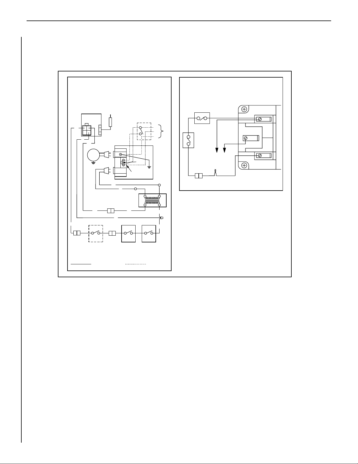
WIRING DIAGRAMS
Wiring diagrams are provided here for reference purposes only. This information is also provided on schematics found on pullout labels located
within the control compartment attached to the gas control valve. Electronic and Millivolt wiring diagrams are provided here.
Electronic Wiring Diagram (Honeywell)
(Optional ON/OFF Switch Wiring)
1. If any of the original wire as supplied must be replaced,
1. it must be replaced with Type AWM 200°C – 18 GA. wire.
2. 120V, 60Hz – Less than 3 amps.
BK
CONTROL
BK
R
WHT
Gas Valve
IGNITER
BL
OPT
FAN
BL
OPTIONAL
ON/OFF SWITCH
OR
WALL SWITCH
Factory Wired
ASSEMBLY
W
BK
PILOT
R
BK
Junction Box
B
DAMPER
SWITCH
OPT. ACCESSORY
SWITCH
Break
Off Tab
To Opposite Side
BL
BK
Transf.
120 V.
24 V
LIMIT
SWITCH
Field Wired
BK
W
VAC.
G
R
BK
If any of the original wire as supplied must be replaced, it
must be replaced with Type AWM 200°C – 18 GA. wire.
Damper Switch
120
BK
Limit
Switch
BK
* For Wall Switch Attachment Only.
SIT Millivolt Wiring Diagram
BK
TP
Thermopile
*
WHT
BK
TH
TP
TH
10
NOTE: DIAGRAMS & ILLUSTRATIONS ARE NOT TO SCALE.
Page 11
LENNOX MERIT® SERIES B-VENT GAS FIREPLACES • 36" LMBV MODELS • CARE AND OPERATION INSTRUCTIONS
H
I
L
O
W
TPTH TP TH
P
I
L
O
T
P
I
L
O
T
O
N
it
O
F
F
OUT
IN
SIT
MILLIVOLT PILOT
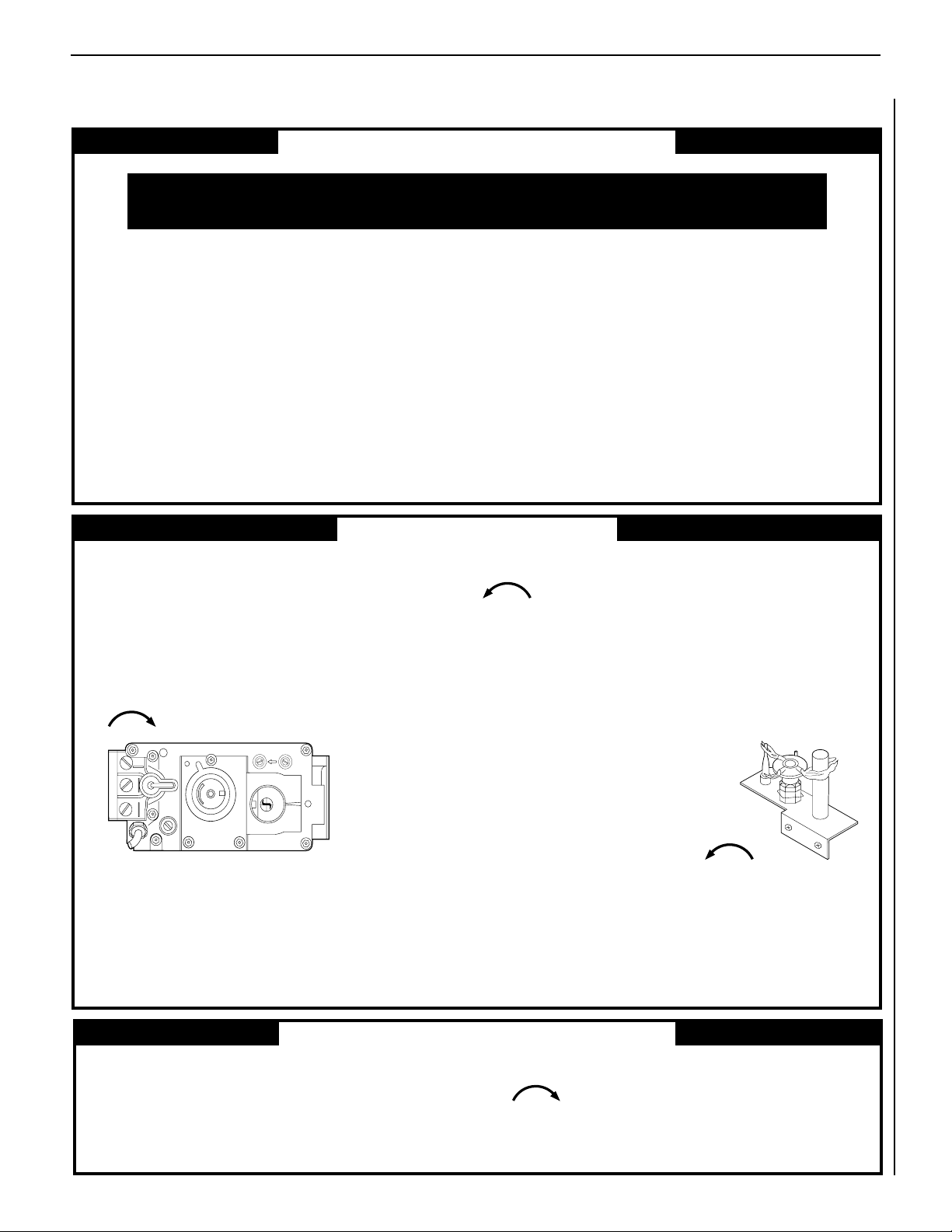
LIGHTING INSTRUCTIONS – HONEYWELL AND SIT MILLIVOLT GAS VALVE
FOR YOUR SAFETY READ BEFORE LIGHTING
WARNING: IF YOU DO NOT FOLLOW THESE INSTRUCTIONS EXACTLY, A FIRE OR EXPLOSION
MAY RESULT CAUSING PROPERTY DAMAGE, PERSONAL INJURY OR LOSS OF LIFE.
A. This appliance has a pilot which must be lighted with a piezo
ignitor. When lighting the pilot, follow these instructions
exactly.
B. BEFORE OPERATING smell all around the appliance area for
gas. Be sure to smell next to the floor because some gas is
heavier than air and will settle on the floor.
WHAT TO DO IF YOU SMELL GAS
• Extinguish any open flame.
• Open windows.
• Do not light any appliance.
• Do not touch any electrical switches.
LIGHTING INSTRUCTIONS
1. STOP! Read the safety information above on this page.
2. Access the lower control compartment.
3. Turn remote wall switch to “OFF.”
4. Verify main line shut-off valve is open.
5. Push in gas control knob slightly and turn clockwise
to “OFF.”
• Do not use any phone in your building.
• Immediately call your gas supplier from a neighbor’s
phone.
• If your gas supplier cannot be reached, call the fire department.
C. Use only your hand to push in or turn the gas control knob.
Never use tools. If the knob will not push in or turn by hand,
do not try to repair it, call a qualified service technician. Force
or attempted repair may result in a fire or an explosion.
D. Do not use this appliance if any part has been under water.
Immediately call a qualified service technician to inspect the
appliance and to replace any part of the control system and
any gas control which has been under water.
7. Push in gas control knob slightly and turn counterclockwise
to “PILOT.”
8. Push in control knob all the way and hold in. Immediately light the
pilot by triggering the spark ignitor (pushing the button) until pilot
lights. Continue to hold the control knob in for about 1 ¹⁄₂ minutes
after the pilot is lit. Release knob and it will pop back up. Pilot
should remain lit. If it goes out, repeat steps 5 through 8.
• If knob does not pop up when released,
stop and immediately call your service
technician or gas supplier.
SIT
MILLIVOLT
GAS VALVE
Note: Knob cannot be turned from “PILOT” to “OFF”
unless the knob is pushed in slightly. Do not force.
6. Wait ve (5) minutes to clear out any gas. If you
then smell gas, STOP! Follow “B” in the safety
information above on this page. If you do not smell
gas, go to the next step.
TO TURN OFF GAS TO APPLIANCE
1. Turn remote wall switch “OFF.” The pilot will remain lit for
normal service.
2. For complete shutdown, turn remote wall switch to “OFF.”
3. Access the lower control compartment.
NOTE: DIAGRAMS & ILLUSTRATIONS ARE NOT TO SCALE.
• If pilot will not stay lit after several tries,
turn the control knob to “OFF” and call
your service technician or gas supplier.
9. Turn gas control knob counterclockwise
to “ON.”
10. Close lower control compartment.
4. Depress gas control knob slightly and turn clockwise
to “OFF.” Do not force.
5. Close lower control compartment.
11
Page 12
LENNOX MERIT® SERIES B-VENT GAS FIREPLACES • 36" LMBV MODELS • CARE AND OPERATION INSTRUCTIONS
H
I
L
O
W
TPTH TP TH
P
I
L
O
T
P
I
L
O
T
O
N
it
O
F
F
OUT
IN
SIT
MILLIVOLT PILOT
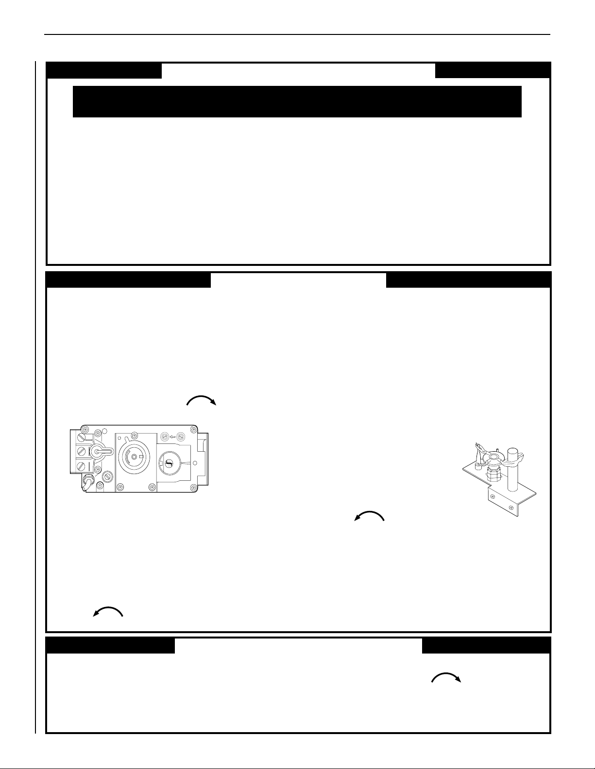
INSTRUCTIONS D’ALLUMAGE – VANNE GAZ MILLIVOLT HONEYWELL ET SIT
POUR VOTRE SÉCURITÉ, LISEZ CES INSTRUCTIONS AVANT L’ALLUMAGE
AVERTISSEMENT : SI VOUS NE SUIVEZ PAS CES INSTRUCTIONS À LA LETTRE, IL POURRAIT S’EN SUIVRE UN INCENDIE OU
UNE EXPLOSION CAUSANT DES DOMMAGES MATÉRIELS, DES BLESSURES CORPORELLES OU MÊME DES PERTES DE VIE.
A. Cet appareil est muni d’une veilleuse qui doit être allumée avec un
allumeur piézo-électrique. Lorsque vous allumez la veilleuse, suivre
exactement ces instructions.
B. AVANT L’ALLUMAGE: Assurez-vous que vous ne détectez aucune odeur
de gaz autour de l’apareil ainsi que près du sol; certains gaz, étant plus
lourds que l’air, descendent au niveau du sol.
VOICI CE QUE VOUS DEVEZ FAIRE SI VOUS DÉCELEZ UNE ODEUR
DE GAZ:
• Éteignez toute flamme visible.
• Ouvrez les fenêtres.
• N’allumez aucun appareil.
• Ne touchez à aucun commutateur électrique.
• Ne vous servez d’aucun téléphone dans votre édifice.
INSTRUCTIONS D'ALLUMAGE
1. ARRÊTEZ! Lisez les consignes de sécurité au verso de cette plaque.
2. Ouvrez le compartiment de contrôle du bas.
3. Tournez l’interrupteur mural à la position d’arrêt “OFF”.
4. Assurez-vous que la soupape d’arrêt de la canalisation principale est
ouverte.
5. Enfoncez légèrement le bouton de réglage du gaz et tournez-le dans
le sens des aiguilles d’une montre jusqu’à la position
d’arrêt “OFF”.
• Appelez immédiatement votre compagnie de gaz en utilisant le téléphone du voisin.
• S’il vous est impossible de contacter votre compagnie de gaz, appelez
le service des incendies.
C. N’utilisez que votre main pour manipuler le bouton de réglage du gaz.
N’utilisez jamais d’outils. Si le bouton refuse de tourner ou de bouger,
n’essayez pas de le réparer. Communiquez immédiatement avec un
technicien de service qualifié. Toute tentative pour le forcer ou le
réparer, risquerait de provoquer un incendie ou une explosion.
D. Ne vous servez pas de cet appareil si l’un de ses éléments a été
immergé dans l’eau. Appelez immédiatement un technicien compétent
pour faire inspecter l’appareil et remplacer toute pièce du système de
réglage ou commande du gaz qui a été sous l’eau.
8. Enfoncez le bouton de réglage jusqu’au fond et gardez-le enfoncé.
Allumez immédiatement la veilleuse en déclenchant l’allume-gaz
à étincelle (en poussant le bouton) jusqu’à ce que la veilleuse
s’enflamme. Continuez de tenir le bouton de réglage enfoncé
pendant environ 90 secondes après l’allumage de la veilleuse.
Relâchez le bouton et il sortira subitement. La veilleuse devrait
rester allumée. Si elle s’éteint, répétez les étapes 5 à 8 inclusivement.
• Si le bouton ne sort pas automatiquement après avoir été relâché,
arrêtez immédiatement et téléphonez à votre technicien de service
ou à votre fournisseur de gaz.
12
VANNE GAZ
MILLIVOLT SIT
Remarque: Il est impossible de tourner le bouton de “PILOT” à “OFF” à
moins qu’il ne soit légèrement enfoncé. Ne le forcez pas.
6. Attendez cinq (5) minutes pour l’evacuation du gaz. Si vous décelez
une odeur de gaz, ARRÊTEZ ! Retournez au point “B” des consignes
de sécurité au verso de cette plaque. Si vous ne remarquez aucune
odeur de gaz, passez à l’étape suivante.
7. Enfoncez légèrement le bouton de réglage du gaz et tournez-le en
sens inverse des aiguilles d’une montre jusqu’à la position de veilleuse “PILOT”.
POUR FERMER LE GAZ QUI ALIMENTE L’APPAREIL
1. Tournez l’interrupteur mural à la position d’arrêt “OFF”. La veilleuse
restera allumée jusqu’au retour du service normal.
2. Pour une fermeture complète, tournez l’interrupteur mural à la posi-
tion d’arrêt “OFF”.
3. Ouvrez le compartiment de contrôle du bas.
NOTE: DIAGRAMS & ILLUSTRATIONS ARE NOT TO SCALE.
• Si la veilleuse refuse de rester allumée
après plusieurs tentatives, tournez le
bouton de réglage jusqu’à sa position
d’arrêt “OFF” et téléphonez à votre
technicien de service ou à votre
fournisseur de gaz.
9. Tournez le bouton de réglage du gaz
en sens inverse des aiguilles d’une
montre jusqu’à sa position
de marche “ON”.
10. Fermez le compartiment de contrôle du bas.
11. Au besoin, rebrancher l’appareil au courant électrique et remettre
l’interrupteur du brûleur principal à la position “ON” ou régler le
thermostat à la température désirée.
12. Si l’appareil ne fonctionne pas, suivre les instructions intitulées
“Pour fermer le gaz qui alimente l’appareil” et appeler un technicien ou le fournisseur de gaz.
4. Enfoncez légèrement le bouton de réglage du gaz et tournez-le dans
le sens des aiguilles d’une montre jusqu’à la position
d’arrêt “OFF”. Ne forcez pas le bouton.
5. Fermez le compartiment de contrôle du bas.
Page 13
LENNOX MERIT® SERIES B-VENT GAS FIREPLACES • 36" LMBV MODELS • CARE AND OPERATION INSTRUCTIONS
ON/OFF Switch
OFF
IN
PSI
ON
CONTROL
IG
N
I
T
E
R
Front View
LIGHTING INSTRUCTIONS — ELECTRONIC
FOR YOUR SAFETY READ BEFORE LIGHTING
WARNING: IF YOU DO NOT FOLLOW THESE INSTRUCTIONS EXACTLY, A FIRE OR EXPLOSION
MAY RESULT CAUSING PROPERTY DAMAGE, PERSONAL INJURY OR LOSS OF LIFE.
A. When lighting the appliance, follow these instructions
exactly.
B. BEFORE OPERATING smell all around the appliance area
for gas. Be sure to smell next to the floor because some
gas is heavier than air and will settle on the floor.
WHAT TO DO IF YOU SMELL GAS
• Extinguish any open flame.
• Open windows.
• Do not light any appliance.
• Do not touch any electrical switches.
• Do not use any phone in your building.
LIGHTING INSTRUCTIONS
1. STOP! Read the safety information above on this page.
2. Turn remote wall switch to “OFF.”
3. Open lower control compartment door.
4. Verify main line shut-off valve is open.
• Immediately call your gas supplier from a neighbor’s
phone.
• If your gas supplier cannot be reached, call the fire
department.
C. Use only your hand to turn the gas control lever. Never
use tools. If the lever will not turn by hand, do not try
to repair it, call a qualified service technician. Force or
attempted repair may result in a fire or an explosion.
D. Do not use this appliance if any part has been under
water. Immediately call a qualified service technician
to inspect the appliance and to replace any part of the
control system and any gas control which has been under
water.
5. Turn the ON/OFF switch to “OFF”. Do not force.
6. Wait ve (5) minutes to clear out any gas. If you then
smell gas, STOP! Follow “B” in the safety information
above on this page. If you do not smell gas, go to the
next step.
7. Turn the ON/OFF switch to “ON”. Do not force.
1. For complete shut-down, turn remote wall switch to
“OFF.”
2. Open lower control compartment door.
8. Turn “ON” all electrical power to appliance (remote wall
switch).
9. Close lower control compartment door.
TO SHUT OFF
1. Turn off all electrical power to the appliance (remote wall
switch).
TO TURN OFF GAS TO APPLIANCE
3. Turn the ON/OFF switch to “OFF”. Do not force.
4. Close the main line shut-off valve.
5. Close lower control compartment door.
13
NOTE: DIAGRAMS & ILLUSTRATIONS ARE NOT TO SCALE.
Page 14
LENNOX MERIT® SERIES B-VENT GAS FIREPLACES • 36" LMBV MODELS • CARE AND OPERATION INSTRUCTIONS
Interrupteur
ON/OFF
OFF
IN
PSI
ON
CONTROL
I
G
N
I
T
E
R
Vue de face
INSTRUCTIONS D’ALLUMAGE — ELECTRONIC
POUR VOTRE SÉCURITÉ, LISEZ CES INSTRUCTIONS AVANT L’ALLUMAGE
AVERTISSEMENT: SI VOUS NE SUIVEZ PAS CES INSTRUCTIONS À LA LETTRE, IL POURRAIT S’EN SUIVRE UN INCENDIE OU UNE
EXPLOSION CAUSANT DES DOMMAGES MATÉRIELS, DES BLESSURES CORPORELLES OU MÊME DES PERTES DE VIE.
A. Lorsque vous allumez l’appareil, suivez exactement ces instruc-
tions.
B. AVANT L’ALLUMAGE: Assurez-vous que vous ne détectez
aucune odeur de gaz autour de l’apareil ainsi que près du sol;
certains gaz, étant plus lourds que l’air, descendent au niveau
du sol.
VOICI CE QUE VOUS DEVEZ FAIRE SI VOUS DÉCELEZ UNE
ODEUR DE GAZ
• Éteignez toute flamme visible.
• Ouvrez les fenêtres.
• N’allumez aucun appareil.
• Ne touchez à aucun commutateur électrique.
• Ne vous servez d’aucun téléphone dans votre édifice.
INSTRUCTIONS D’ALLUMAGE
1. ARRÊTEZ ! Lisez les consignes de sécurité au verso de cette
plaque.
2. Tournez l’interrupteur mural à la position d’arrêt “OFF”.
3. Ouvrez la porte du compartiment de contrôle du bas.
4. Assurez-vous que la soupape d’arrêt de la canalisation principale
est ouverte.
• Appelez immédiatement votre compagnie de gaz en utilisant
le téléphone du voisin.
• S’il vous est impossible de contacter votre compagnie de
gaz, appelez le service des incendies.
C. N’utilisez que votre main pour manipuler linterrupteur
“ON/OFF” de la valve à gaz. N’utilisez jamais d’outils. Si
l’interrupteur ne bouge pas manuellement, n’essayez pas de le
réparer. Communiquez immèdiatement avec un technicien de
service qualifié. Toute tentative pour forcer l’interrupteur ou le
réparer, risquerait de provoquer un incendie ou une explosion.
D. Ne vous servez pas de cet appareil si l’un de ses éléments a
été immergé dans l’eau. Appelez immédiatement un technicien
compétent pour faire inspecter l’appareil et remplacer toute
pièce du système de réglage ou commande du gaz qui a été
sous l’eau.
6. Attendez cinq (5) minutes pour l’evacuation du gaz. Si vous
décelez une odeur de gaz ARRÊTEZ ! Retournez au point “B”
des consignes de sécurité au verso de cette plaque. Si vous ne
remarquez aucune odeur de gaz, passez à l’étape suivante.
7. Tournez la manette de réglage du gaz jusqu’à la position de
marche “ON”. Ne la forcez pas.
8. Ouvrez le courant électrique (“ON”) qui alimente l’appareil
(interrupteur mural).
14
5. Tournez la manette de réglage du gaz à la position d’arrêt “OFF”.
POUR FERMER LE GAZ QUI ALIMENTE L’APPAREIL
1. Pour une fermeture complète, tournez l’interrupteur mural à la
position d’arrêt “OFF”.
2. Ouvrez la porte du compartiment de contrôle du bas.
NOTE: DIAGRAMS & ILLUSTRATIONS ARE NOT TO SCALE.
9. Fermez la porte du compartiment de contrôle du bas.
10. Au besoin, rebrancher l’apareil au courant électrique et
remettre l’interrupteur principal du brûleur à la position “ON”
ou régler le thermostat à la température désirée.
11. Si l’appareil ne se met pas en marche, suivre les instruc-
tions intitulées “Pour fermer le gaz qui alimente l’appareil” et
appeler un technicien ou le fournisseur de gaz.
POUR ÉTEINDRE L’APPAREIL
1. Coupez tout le courant électrique qui alimente l’appareil (inter-
rupteur mural).
3. Tournez la manette de réglage du gaz à la position d’arrêt “OFF”.
Ne la forcez pas.
4. Fermez la soupape d’arrêt de la canalisation principale.
5. Fermez la porte du compartiment de contrôle du bas.
Page 15
LENNOX MERIT® SERIES B-VENT GAS FIREPLACES • 36" LMBV MODELS • CARE AND OPERATION INSTRUCTIONS
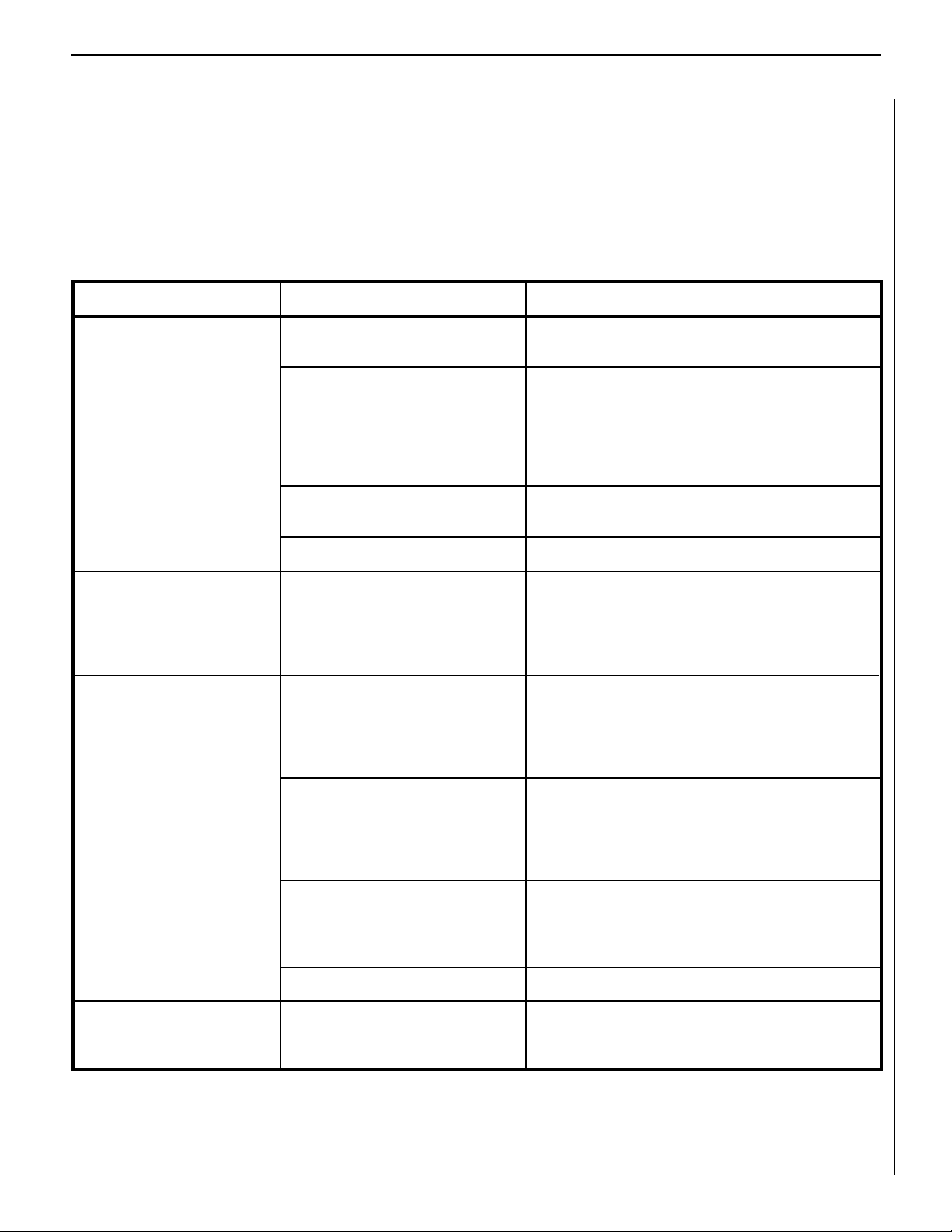
TROUBLESHOOTING THE MILLIVOLT GAS CONTROL SYSTEM
Note: Before troubleshooting the gas control system, be sure external gas shut off valve (located at gas supply inlet) is in
the “ON” position.
Important: Valve system troubleshooting should only be accomplished by a qualified service technician.
1. Spark ignitor will not light
pilot after repeated triggering
of ignitor button.
2. Pilot will not stay lit after
carefully following the lighting instructions.
3. Pilot burning, no gas to
burner, Valve knob “ON,”
Wall Switch “ON.”
POSSIBLE CAUSES
A. Defective ignitor
(no spark at electrode).
B. Defective or misaligned electrode
at pilot (spark at electrode).
C. Gas supply pressure errant.
D. Pilot orifice plugged.
A. Defective pilot generator (thermo-
generator).
A. Damper closed or Damper Switch
defective.
CORRECTIVE ACTIONSYMPTOM
Check for spark at electrode and pilot; if no spark and electrode
wire is properly connected, replace ignitor.
Using a match, light pilot. If pilot lights, turn off pilot and
trigger the ignitor button again. If pilot lights, an improper
gas mixture caused the bad lighting and a longer purge
period is recommended. If pilot will not light – check gap at
electrode and pilot - should be 1/8" to have a strong spark.
If gap measures 1/8", replace pilot (Figure 9 ).
Check inlet gas pressure. It should be within the limits as
marked on the rating plate.
Clean or replace pilot orifice.
Check pilot flame, it must impinge on thermogenerator (Figure
9 ). Clean and/or adjust pilot for maximum flame impingement
on thermogenerator. Ensure that the connection between the
valve and thermogenerator are tight and secure.
Ensure damper control lever is locked in the open position,
all the way to the right. If the damper control lever is locked
in the open position troubleshoot through Steps B., C. and D.
below. If the main burner will still not light, determine if the
damper switch is defective and replace if necessary.
4. Frequent pilot/burner outage
problem.
B. Wall switch or wires defective.
C. Thermopile may not be generating
sufficient millivoltage.
D. Plugged burner orifice.
A. Pilot flame may be too low or
blowing (high) causing the pilot/
valve safety to drop out.
NOTE: DIAGRAMS & ILLUSTRATIONS ARE NOT TO SCALE.
Check wall switch and wires for proper connections. Jumper
wire across terminals at wall switch, if burner comes on,
replace defective wall switch. If okay, jumper wires across
wall switch wires at valve, if burner comes on, wires are faulty
or connections are bad.
Check thermopile with millivolt meter. Take reading at ther-
mopile terminals of gas valve. Should read 325 millivolts
minimum with optional wall switch “OFF.” Replace faulty
thermopile if reading is below specified minimum.
Check burner orifice for stoppage and remove.
Clean and/or adjust pilot flame for maximum flame impingement on thermogenerator (Figure 9 ).
15
Page 16
LENNOX MERIT® SERIES B-VENT GAS FIREPLACES • 36" LMBV MODELS • CARE AND OPERATION INSTRUCTIONS
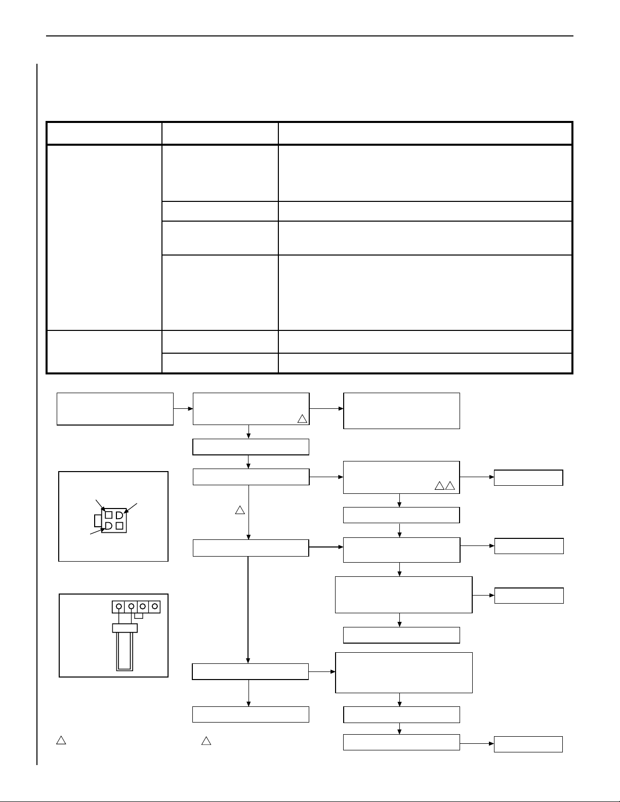
• Turn Off Gas Supply
• Assure Valve Switch Is In ON Position
• Disconnect Control Harness
• Set Thermostat To Call For Heat
• Check For Proper Voltage At Control Harness
(See Insert A). Voltage Should Be 24V
Between Thermostat Or Pressure Switch
And 24V Common And 24V Hot.
• Line Voltage Power
• Low Voltage Transformer
• Limit Controller
• Thermostat
• Wiring
2
CHECK
START
NO
• Plug Control Harness Into Valve. Wait For
Internal Check Delay.
YES
• Igniter Warms Up And Glows Red.
• With Pilot Burner Cable Connected, Measure
Voltage At Valve HSI Element Output. 24V
Nominal. (See Insert B)
NO
• Replace Igniter/Flame Rod Assembly.
YES
• Replace Valve.
NO
• Turn On Gas Supply. • Pilot Burner Lights.
• Check That Pilot Gas Is Flowing. Wait To
Assure Plot Gas Tubing Is Purged. Recycle
Call For Heat If Necessary.
NO
YES
NO
YES
YES
1
• Measure Voltage Between 24V Hot And 24V Common
Leads To Valve Control. Must Measure At Least 19.5
VAC With Igniter Powered (See Insert A). To Identify
Proper Lead, This Check Must Be Done With The
Valve Control Connected And Igniter Powered.
• Check Transformer And
Line Volt Supply.
NO
• Replace Pilot Assembly.
YES
• Check That Pilot Flame Makes Good Contact With
Pilot Burner Flame Rod.
• Check For Good Electrical Connection Through The
Pilot Tubing.
• If Both Of The Above Are Good, Replace Igniter/Flame
Rod Assembly.
• Cycle Thermostat Off And Back On.
YES
• Main Valve Opens And Main Burner Lights.
NO
YES
• System Is Okay.
YES
• Main Burner Lights.
NO
2
1
Igniter Will Cycle Off And Back On Once During
The 90 Second Ignition Trial. All Voltage
Measurements Must Be Taken While The Igniter
Is Powered.
When Measured Voltage At Connections, Use
Care To Assure Terminals Are Not Damaged.
• Replace Valve.
• Replace Valve.
24 Volt Hot
End View Of
Control Harness
Connector
24 Volt
Common
24 Volt
Switched
Check For Damaged Or Missing Terminals
In Connector
Insert A
Igniter Terminals
Insert B
2
1
TROUBLESHOOTING THE ELECTRONIC IGNITION SYSTEM
Note: Before troubleshooting, be sure that the appliance main line gas shut-off valve, the gas control valve and the wall switch are in the “ON” position.
Important: Valve system troubleshooting should only be accomplished by a qualified service technician.
SYMPTOM POSSIBLE CAUSES CORRECTIVE ACTION
1. Burner will not light.
2. Burners come “ON” but
go “OFF.”
A. Damper closed or
Damper Switch defective.
B. Faulty Valve System.
C. Faulty limit switch.
D. “OFF/ON” or wall switch
defective.
A. Burner orifice plugged.
B. Obstructed vent system.
Ensure damper control lever is locked in the open position, all the way to the
right. If the damper control lever is locked in the open position troubleshoot
through Steps B., C. and D. below. If the main burner will still not light, determine if the damper switch is defective and replace if necessary.
See Below.
Reset the limit switch button. If still not working, access the leads attached to the
limit switch and check for continuity. If no continuity, replace limit switch.
Disconnect the two black wires from the wire nuts. Test switch(s) for continuity with a multimeter. If continuity is not indicated, switch(s) is defective and
must be replaced.
Note: Before replacing “OFF/ON” switch, be sure to check wiring for loose
connections or broken wires and repair as needed.
Check main burner orice(s) for stoppage. Clean or replace.
Check vent system for obstructions.
16
NOTE: DIAGRAMS & ILLUSTRATIONS ARE NOT TO SCALE.
Page 17
LENNOX MERIT® SERIES B-VENT GAS FIREPLACES • 36" LMBV MODELS • CARE AND OPERATION INSTRUCTIONS
WARRANTY
Your gas appliance is covered by a limited twenty
year warranty. You will find a copy of the warranty accompanying this manual. Please read
the warranty to be familiar with its coverage.
Retain this manual. File it with your other documents for future reference.
REPLACEMENT PARTS
A complete parts list is found at the end of
this manual. Use only parts supplied from the
manufacturer.
Normally, all parts should be ordered through
your Lennox distributor or dealer. Parts will be
shipped at prevailing prices at time of order.
PRODUCT REFERENCE INFORMATION
We recommend that you record the following important information about your fireplace. Please
contact your Lennox dealer for any questions or concerns. For the number of your nearest Lennox
dealer, please call 1-800-9-LENNOX
Fireplace Model Number _____________________________________________
Fireplace Serial Number ______________________________________________
Date Fireplace Was Installed __________________________________________
Type of Gas Used in Fireplace _________________________________________
Your Dealer's Name ________________________________________________
When ordering repair parts, always give the
following information:
1. The model number of the appliance.
2. The serial number of the appliance.
3. The part number.
4. The description of the part.
5. The quantity required.
6. The installation date of the appliance.
If you encounter any problems or have any
questions concerning the installation or application of this system, please contact your
distributor. For the name of your nearest
distributor contact:
Lennox Hearth Products
1508 Elm Hill Pike, Suite 108
Nashville, TN 37210
NOTE: DIAGRAMS & ILLUSTRATIONS ARE NOT TO SCALE.
17
Page 18
LENNOX MERIT® SERIES B-VENT GAS FIREPLACES • 36" LMBV MODELS • CARE AND OPERATION INSTRUCTIONS
ACCESSORY COMPONENTS
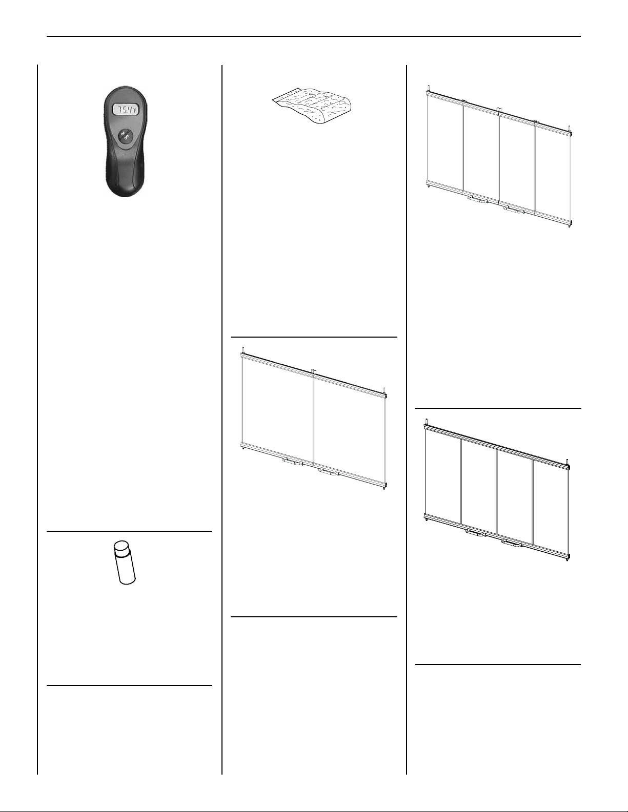
Remote Control System (Standard) H0249 RCL
Standard Remote Control System
(Model RCL)
The Model RCL (Standard) Remote Control
System, features a simplistic on/off control
function for the fireplace. This model includes
a hand-held transmitter, a remote receiver with
wall-mount coverplate and all hardware required
to install the unit. The remote receiver can be
wall or hearth mounted.
The transmitter has ON and OFF functions that
are activated by pressing either button on the
face of the transmitter. When a button on the
transmitter is pressed, a signal light illuminates
briefly to verify that a signal has been sent.
Decorative Volcanic Stone 80L42 FDVS
Bag of Rockwool 88L53 FGE
Decorative Volcanic Stone
The decorative volcanic stone, Model FDVS, can
be used to enhance the look of your appliance.
Spread the decorative volcanic stone evenly
around the bottom of the firebox.
Bag of Rockwool
Replacement ember materials are available
for use with these appliances. Order a bag
of Rockwool, Model FGE to replace ember
materials as part of the periodic maintenance
of the appliance.
86L26 36 ABF
86L27 36 ABF-BB
86L28 36 ABF-BS
12M01 36BF
Bi-Fold Doors 12M02 36BF-BB
Bi-Fold Doors
Your appliance can be fitted with beautiful bifold doors. Model ABF doors are available for
use with these appliances. Doors are easily
tted to the replace opening. Model 36 ABF
doors come with standard black finish. Model
36 ABF-BB doors have a beautiful bright brass
nish. Model 36 ABF-BS doors have a brushed
stainless finish.
The Model RCL is designed to operate with all
millivolt ignition systems, as well as electronic
ignition systems. It may be installed with use
for either natural or propane gas appliances.
The RCL offers ease of installation and allows
you to execute on-off commands to the fireplace
effortlessly with one simple motion.
The Model RCL comes complete with detailed
operating instructions.
Touch-Up Paint Kit 90L73 FTPK-B
Touch-Up Paint Kit
Repair of minor scratches and discoloration of
the appliance black painted surfaces may be
accomplished with the touch-up paint kit.
Twin Pane Doors 86L29 36 TPA-BB
Twin Pane Doors
Your appliance can be fitted with beautiful twin
pane doors. Model TPA doors are available
for use with these appliances. Model TPA
doors are easily fitted to the fireplace opening.
Model 36 TPA-BB doors have a beautiful bright
brass finish.
Glass Enclosure Panels 27M30 36GEP
27M31 36GEP-BB
Your fireplace can be fitted with beautiful glass
enclosure panels with a bi-fold "look" (nonoperable doors once installed). Model 36GEP
is nished in black trim; model 36GEP-BB is
finished in polished brass trim.
To ensure warranty and to prevent a potential
fire hazard, do not use any other doors on
these appliances.
18
NOTE: DIAGRAMS & ILLUSTRATIONS ARE NOT TO SCALE.
Page 19
LENNOX MERIT® SERIES B-VENT GAS FIREPLACES • 36" LMBV MODELS • CARE AND OPERATION INSTRUCTIONS
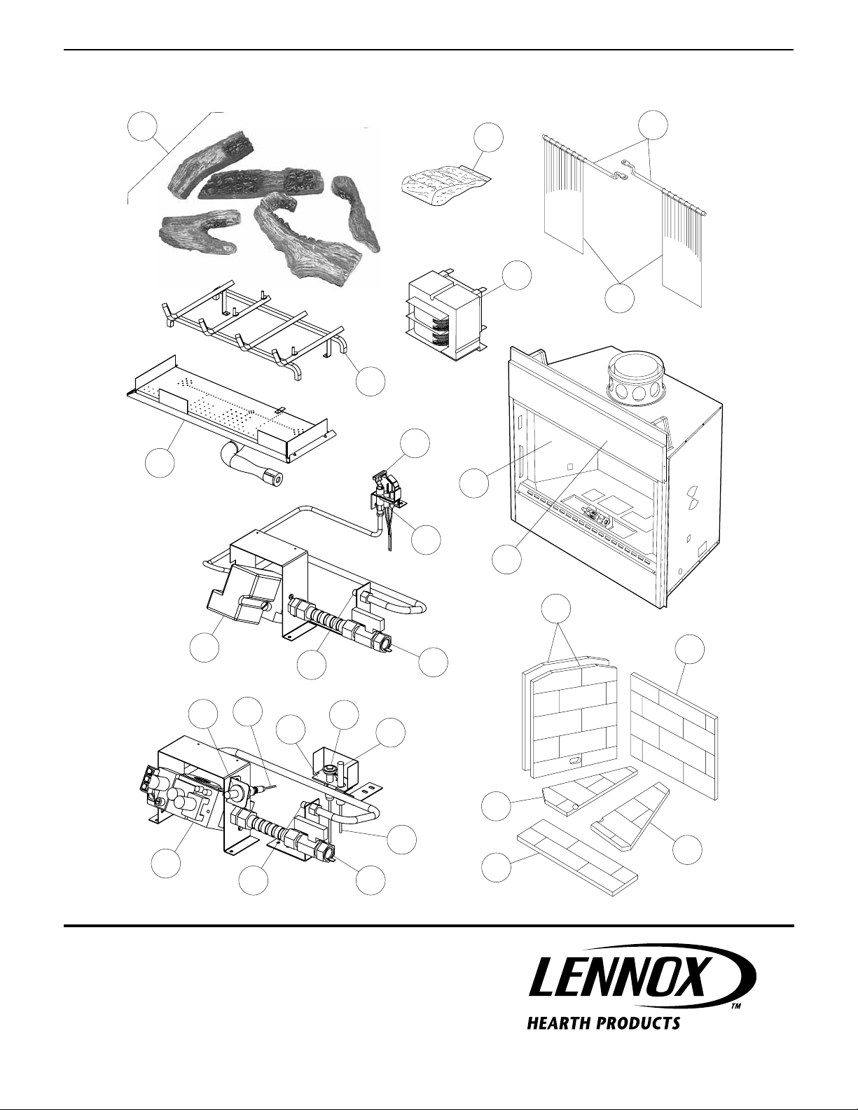
REPLACEMENT PARTS LIST
Natural Propane
No. DESCRIPTION Part No. Qty. Part No. Qty.
Gas Fireplace Assembly – – – –
1. Firescreen H4167 2 H4167 2
2. Rod, Screen H3610 2 H3610 2
3. Refractory, Side 88L59 2 88L59 2
4. Refractory, Rear 88L58 1 88L58 1
5. Refractory Access Panel H3656 1 H3656 1
6. Refractory, Base (Left) H3655 1 H3655 1
7. Refractory, Base (Right) H3657 1 H3657 1
8. Log Set, Complete H5132 1 H5132 1
a. Log, Rear – 1 – 1
b. Log, Rear Top – 1 – 1
c. Log, Front Left – 1 – 1
d. Log, Top Right – 1 – 1
e. Log, Front Right – 1 – 1
9. Burner Assembly H5351 1 H5351 1
10. Burner Orice H3721 1 67L28 1
11. Bag of Rockwool 88L53 1 88L53 1
12. Limit Switch 75L23 1 75L23 1
13. Damper Switch 94468 1 94468 1
14. Flexible Gas Line And valve 93L32 1 93L32 1
15. Grate Assembly H5352 1 H5352 1
GAS CONTROLS — MILLIVOLT
Natural Propane
No. DESCRIPTION Part No. Qty. Part No. Qty.
20. Gas Valve - SIT H1658 1 H1659 1
21. Pilot Assembly (SIT) 62L12 1 62L13 1
22. Pilot Generator 60J79 1 60J79 1
23. Electrode And Cable 74L58 1 74L58 1
24. Piezo Ignitor 10K86 1 10K86 1
25. Ignition Cable H5047 1 H5047 1
26. Pilot Tube 74L56 1 74L56 1
GAS CONTROLS — ELECTRONIC
Natural Propane
No. DESCRIPTION Part No. Qty. Part No. Qty.
30. Gas Valve - Honeywell 62L18 1 62L19 1
31. Pilot Assembly (Honeywell) 62L14 1 62L15 1
32. Transformer 42J32 1 42J32 1
33. Ignitor Assembly (Kit) 87L54 1 87L54 1
NOTE: DIAGRAMS & ILLUSTRATIONS ARE NOT TO SCALE.
19
Page 20
LENNOX MERIT® SERIES B-VENT GAS FIREPLACES • 36" LMBV MODELS • CARE AND OPERATION INSTRUCTIONS
REPLACEMENT PARTS
8
b.
11
2
a.
d.
c.
e.
32
1
15
31
9
12
33
30
14
24
25
21
10
23
22
26
20
10
REF
Lennox Hearth Products reserves the right to make changes at any time, without notice, in
design, materials, specifications, and prices, and also to discontinue colors, styles, and products.
Consult your local distributor for fireplace code information.
14
REF
NOTE: DIAGRAMS & ILLUSTRATIONS ARE NOT TO SCALE.
13
3
4
6
7
5
Printed in U.S.A. © 2006 by Lennox Hearth Products
20
P/N 875033M REV. C 07/2010
1508 Elm Hill Pike, Suite 108 • Nashville, TN 37210
 Loading...