

Lennox LGH092H4B, LGH094U4E, LGH102H4B, LGH092H4M, LGH120H4B Unit Information
...
Corp. 1008-L2
Service Literature
Revised 5/2015
LGH092H through 152U
The LGH092H, 094U, 102H, 120H, 122U, 150S and
152U units are configure to order units (CTO) with a wide
selection of factory-installed options. Units are avail
able in 130,000, 180,000 Btuh or 240,000 Btuh (38.1,
52.7 or 70.3 kW) heating inputs. Gas heat sections are
designed with Lennox' aluminized steel tube heat ex
changers with stainless steel as an option.
Cooling capacities range from 7.5 to 12.5 tons (38.1 to
70.3 kW). All units are equipped with two compressors.
Ultra-high efficiency units are available with an optional di
rect drive blower or belt drive blower equipped with a sup
ply air inverter. Standard and high efficiency units are
available with a belt drive blower equipped with an option
al supply air inverter. The blower will operate at lower
speeds when demand is low and increase to higher
speeds when demand is high.
The following examples show the model numbers of tenton units with all available blower options:
LGH120H4B High Efficiency Belt Drive
LGH120H4M High Efficiency Belt Drive with Inverter
LGH122U4M Ultra High Efficiency Belt Drive with Inverter
LGH122U4E Ultra High Efficiency Direct Drive
Note - Ten-ton units are available in high and ultra high effi
ciencies only.
Standard and high efficiency units come standard with a
lightweight, all-aluminum condenser coil; optional, fin/
tube condenser coils are available. Ultra-high efficiency
units come standard with a tube/fin condenser coil.
Ultra high efficiency units come standard with two singlespeed compressors plumbed in tandem to form a single re
frigerant circuit.
Units are also designed for R410A refrigerant. See unit
nameplate. Operating pressures and pressure switch set
tings are significantly higher than R22 charged units. Ser
vice equipment must be rated for R410A.
Standard and high efficiency units offer mechanical cooling
down to 0°F when properly equipped. Ultra-high efficiency
units offer mechanical cooling down to 40°F.
All LGH units are designed to accept any of several differ
ent energy management thermostat control systems with
minimum field wiring. Factory or field provided control op
tions connect to the unit with jack plugs. When ”plugged in”
the controls become an integral part of the unit wiring.
Information contained in this manual is intended for use by
qualified service technicians only. All specifications are
subject to change. Procedures outlined in this manual are
presented as a recommendation only and do not super
sede or replace local or state codes.
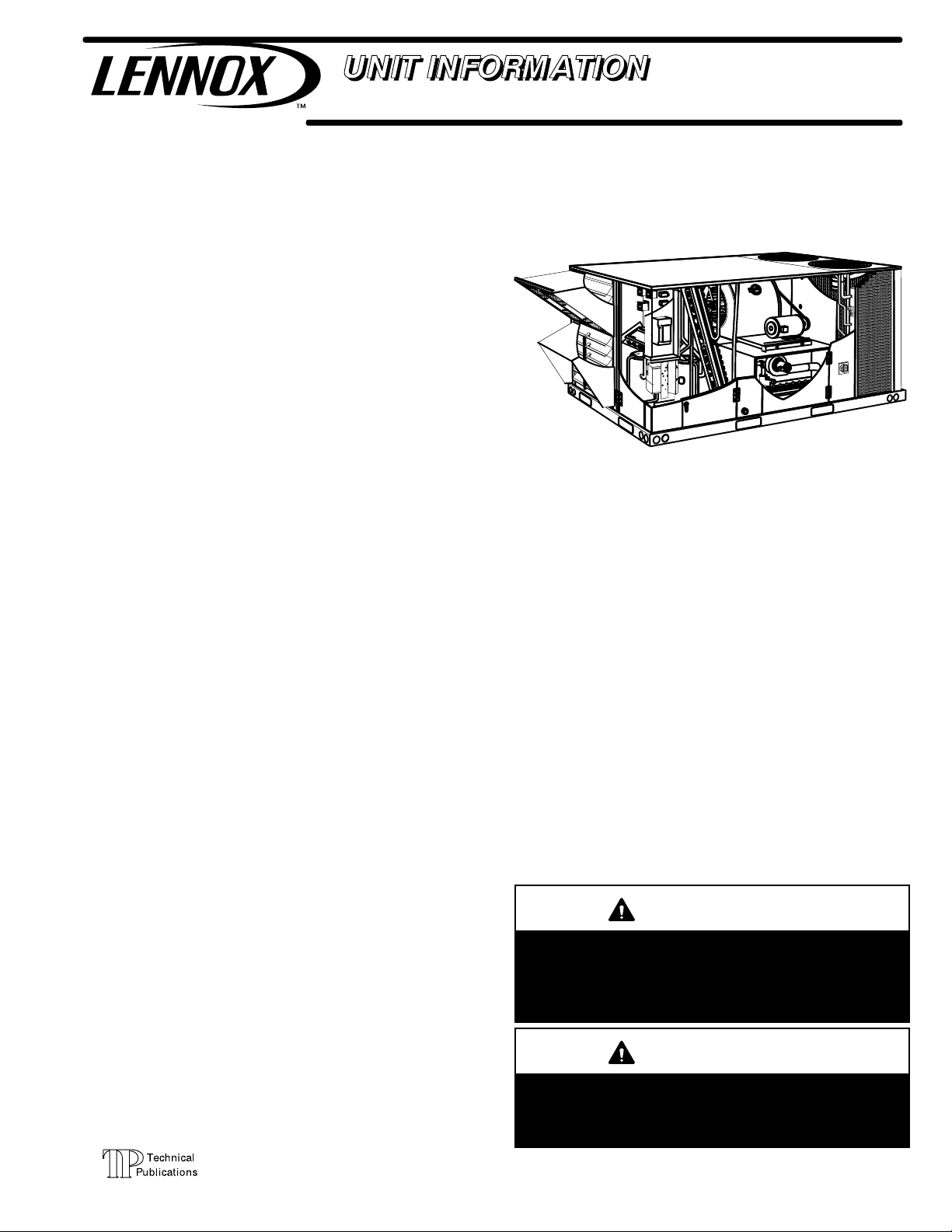
LGH SERIES
7.5 to 12.5 ton
38.1 to 70.3 kW
If the unit must be lifted for service, rig unit by attaching four
cables to the holes located in the unit base rail (two holes at
each corner). Refer to the installation instructions for the
proper rigging technique.
3
3
Table of Contents
Options / Accessories Page 2.....................
Specifications Page 8............................
Blower Tables Page 14............................
Electrical Data Page 19...........................
Parts Arrangement Page 25.......................
I-Unit Components Page 28.......................
II-Placement and Installation Page 47...............
III-Charging Page 47..............................
IV-Start Up - Operation Page 55....................
V-System Service Checks Page 57................
High Altitude Page 59.........................
VI-Maintenance Page 59..........................
VII-Accessories Page 60..........................
VIII-Belt Drive Supply Air Inverter Page 67...........
IX-Direct Drive Supply Air Blower Page 70...........
X-Staged Supply Air Operation Page 71.............
XI-Wiring and Operation Sequence Page 72.........
WARNING
Improper installation, adjustment, alteration, service
or maintenance can cause property va, personal in
jury or loss of life. Installation and service must be
performed by a licensed professional HVAC installer
or equivalent, service agency, or the gas supplier
CAUTION
As with any mechanical equipment, contact with
sharp sheet metal edges can result in personal in
jury. Take care while handling this equipment and
wear gloves and protective clothing.
© 2015
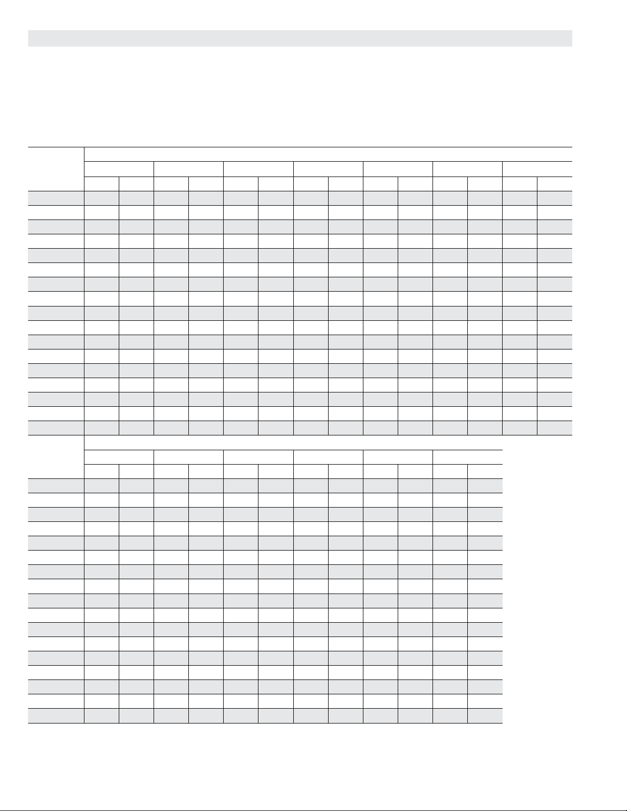
OPTIONS / ACCESSORIES - 092H, 102H, 120H, 150S
Item Description
Model
Number
Catalog
Number
COOLING SYSTEM
Condensate Drain Trap PVC - C1TRAP20AD2 76W26 OX OX OX OX
Copper - C1TRAP10AD2 76W27 OX OX OX OX
Conventional Fin/Tube Condenser Coil (replaces all-aluminum coil) Factory O O O O
Corrosion Protection Factory O O O O
Drain Pan Overow Switch E1SNSR71AD1 68W88 OX OX OX OX
Refrigerant Type R-410A O O O O
Service valves (not for all-aluminum coil equipped units) Factory O O O O
HEATING SYSTEM
Bottom Gas Piping Kit C1GPKT01B-01 54W95 OX OX OX OX
Combustion Air Intake Extensions T1EXTN10AN1 19W51 X X X X
Gas Heat Input 130,000 Btuh Factory O O O O
180,000 Btuh Factory O O O O
240,000 Btuh Factory O O O O
Low Temperature Vestibule Heater 208/230V-3ph - C1LTVH10B-1Y 55W91 OX OX OX OX
460V - C1LTVH10B-1G 55W92 OX OX OX OX
575V - C1LTVH10B-1J 55W93 OX OX OX OX
LPG/Propane Conversion Kits Standard Heat - E1LPCO10B-1 53W07 X X X X
Medium Heat - E1LPCO20B-1 53W08 X X X X
High Heat - E1LPCO30B-1 53W09 X X X X
Stainless Steel Heat Exchanger Factory O O O O
Vertical Vent Extension Kit C1EXTN2021 42W16 X X X X
BLOWER - SUPPLY AIR
Blower Option CAV (Constant Air Volume) Factory O O O O
Multi-Stage Air Volume supply air blower option (With VFD Bypass Control) Factory O O O O
Multi-Stage Air Volume supply air blower option (Without VFD Bypass Control) Factory O O O O
Motors - Constant Air
Volume (CAV)
Belt Drive (standard or high efciency) - 2 hp Factory O O O O
Belt Drive (standard or high efciency) - 3 hp Factory O O O O
Belt Drive (standard efciency) - 5 hp Factory O O O O
Motors -
Multi-Stage Air Volume
Belt Drive (standard or high efciency) - 3 hp Factory O O O O
Belt Drive (high efciency) - 2 hp Factory O O O O
Belt Drive (standard efciency) - 5 hp Factory O O O O
Drive Kits
See Blower Data Tables for selection
Kit #1 590-890 rpm Factory O O O O
Kit #2 800-1105 rpm Factory O O O O
Kit #3 795-1195 rpm Factory O O O O
Kit #4 730-970 rpm Factory O O O O
Kit #5 940-1200 rpm Factory O O O O
Kit #6 1015-1300 rpm Factory O O O O
Kit #7 730-970 rpm Factory O O O O
Kit #8 940-1200 rpm Factory O O O O
Kit #9 1015-1300 rpm Factory O O O O
Kit #10 900-1135 rpm Factory O O O O
Kit #11 1040-1315 rpm Factory O O O O
Kit #12 1125-1425 rpm Factory O O O O
Blower Belt Auto-Tensioner Factory O O O O
CABINET
Combination Coil/Hail Guards All-Aluminum Coil - E1GARD21B-1 13T05 X X X X
Conventional Fin/Tube Condenser Coil - E1GARD20B-1 13T04 X X X X
Horizontal Discharge Kit K1HECK00B-1 51W25 X X X X
Return Air Adaptor Plate (for LC/LG/LH and TC/TG/TH unit replacement) C1CONV10B-1 54W96 OX OX OX OX
NOTE - Catalog and model numbers shown are for ordering eld installed accessories.
OX - Congure To Order (Factory Installed) or Field Installed
O = Congure To Order (Factory Installed)
X = Field Installed
Unit Model No
092 102 120 150
Page 2
OPTIONS / ACCESSORIES - 092H, 102H, 120H, 150S
Item Description
Model
Number
Catalog
Number
CONTROLS
Blower Proving Switch C1SNSR35FF1 53W65 OX OX OX OX
Commercial Controls L Connection
Prodigy
®
Control System - BACnet® Module - C0CTRL60AE1L 59W51 OX OX OX OX
®
Prodigy
Control System - LonTalk® Module - C0CTRL65FF1 54W27 OX OX OX OX
®
Building Automation System - - - X X X X
®
ETM-2051 - E0CTRL30B1
Novar
Novar
®
LSE
64W73 OX OX OX OX
Factory O O O O
Dirty Filter Switch E1SNSR55B-1 53W67 OX OX OX OX
Fresh Air Tempering C1SNSR75AD1 58W63 OX OX OX OX
Smoke Detector - Supply or Return (Power board and one sensor) C1SNSR44B-2 11K76 OX OX OX OX
Smoke Detector - Supply and Return (Power board and two sensors) C1SNSR43B-2 11K80 OX OX OX OX
INDOOR AIR QUALITY
Air Filters
High Efciency Air Filters
20 x 25 x 2 (Order 4 per unit)
Replacement Media Filter With Metal Mesh
MERV 8 - C1FLTR15B-1 50W61 OX OX OX OX
MERV 13 - C1FLTR40B-1 52W41 OX OX OX OX
C1FLTR30B-1- Y3063 X X X X
Frame (includes non-pleated lter media)
Indoor Air Quality (CO
Sensor - Wall-mount, off-white plastic cover with LCD display C0SNSR50AE1L 77N39 X X X X
) Sensors
2
Sensor - Wall-mount, off-white plastic cover, no display C0SNSR52AE1L 87N53 X X X X
Sensor - Black plastic case with LCD display, rated for plenum
mounting
Sensor - Wall-mount, black plastic case, no display, rated for
plenum mounting
Sensor Duct Mounting Kit - for downow applications C0MISC19AE1- 85L43 X X X X
CO
2
Aspiration Box - for duct mounting non-plenum rated CO
(87N53 or 77N39)
UVC Germicidal Lamps
1
UVC Light Kit (208/230v-1ph) C1UVCL10B-1 54W62 OX OX OX OX
sensors
2
C0SNSR51AE1L 87N52 X X X X
C0MISC19AE1 87N54 X X X X
C0MISC16AE1- 90N43 X X X X
ELECTRICAL
Voltage 60 hz 208/230V - 3 phase Factory O O O O
460V - 3 phase Factory O O O O
575V - 3 phase Factory O O O O
HACR Circuit Breakers Factory O O O O
Disconnect Switch 80 amp - C1DISC080B-1 54W56 OX OX OX OX
150 amp - C1DISC150B-1 54W57 OX OX OX OX
GFI Service
Outlets
15 amp non-powered, eld-wired (208/230V, 460V only) LTAGFIK10/15 74M70 OX OX OX OX
20 amp non-powered, eld-wired (575V only) C1GFCI20FF1 67E01
Weatherproof Cover for GFI C1GFCI99FF1 10C89 X X X X
Phase/Voltage Detection (Optional for CAV options only, furnished with staged blower option) Factory O O O O
ECONOMIZER
Standard Economizer (Not for Title 24)
Standard Economizer
E1ECON15B-1 55W05 OX OX OX OX
Downow or Horizontal - Includes Outdoor Air Hood and Downow
Barometric Relief Dampers with Exhaust Hood
Order Horizontal Barometric Relief Dampers separately
High Performance Economizer (Approved for California Title 24 Building Standards)
High Performance Economizer
E1ECON17B-1 10U59 OX OX OX OX
Downow or Horizontal - Includes Outdoor Air Hood and Downow
Barometric Relief Dampers with Exhaust Hood
Order Horizontal Barometric Relief Dampers separately
Horizontal Barometric Relief Dampers
Horizontal Low Prole Barometric With Exhaust Hood LAGEDH03/15 53K04 X X X X
Economizer Controls (Not for Title 24)
Differential Enthalpy Order 2 - C1SNSR64FF1 53W64 OX OX OX OX
Sensible Control Sensor is Furnished Factory O O O O
Single Enthalpy C1SNSR64FF1 53W64 OX OX OX OX
Global Control Sensor Field Provided Factory O O O O
1
Lamps operate on 110-230V single-phase power supply. Step-down transformer may be ordered separately for 460V and 575V units. Alternately, 110V power supply
may be used to directly power the UVC ballast(s)
NOTE - Catalog and model numbers shown are for ordering eld installed accessories.
OX - Congure To Order (Factory Installed) or Field Installed
O = Congure To Order (Factory Installed)
X = Field Installed
Page 3
Unit Model No
092 102 120 150
OX OX OX OX
OPTIONS / ACCESSORIES - 092H, 102H, 120H, 150S
Item Description
Model
Number
Catalog
Number
OUTDOOR AIR
Outdoor Air Dampers With Outdoor Air Hood
Motorized E1DAMP20B-1 63W60 OX OX OX OX
Manual C1DAMP10B-1 53W48 OX OX OX OX
POWER EXHAUST
Standard Static 208/230V-3ph - K1PWRE10B-1Y 53W44 OX OX OX OX
460V-3ph - K1PWRE10B-1G 53W45 OX OX OX OX
575V-3ph - K1PWRE10B-1J 53W46 OX OX OX OX
®
HUMIDITROL
Humiditrol
CONDENSER REHEAT OPTION
®
Dehumidication Option (NOTE - Not available all-aluminum condenser coil.
Factory O O O O
Conventional Fin/Tube condenser coil must be ordered as a factory option)
Humidity Sensor Kit, Remote mounted (required) C0SNSR31AE-1 17M50 X X X X
ROOF CURBS
Hybrid Roof Curbs, Downow
8 in. height C1CURB70B-1 11F54 X X X X
14 in. height C1CURB71B-1 11F55 X X X X
18 in. height C1CURB72B-1 11F56 X X X X
24 in. height C1CURB73B-1 11F57 X X X X
Adjustable Pitch Curb, Downow
14 in. height C1CURB55B-1 54W50 X X X X
CEILING DIFFUSERS
Step-Down - Order one RTD11-95 29G04 X
RTD11-135 29G05 X X
RTD11-185 29G06 X
Flush - Order one FD11-95 29G08 X
FD11-135 29G09 X X
FD11-185 29G10 X
Transitions (Supply and Return) - Order one C1DIFF30B-1 12X65 X
C1DIFF31B-1 12X66 X X
C1DIFF32B-1 12X67 X
®
Sunsource
Solar Module CE
Kit
Commercial Energy System
One 285W Solar Module (silver frame), One PanelClaw Polar Bear III
Mounting System and One Enphase M250 Microinverter
10U67 X X X X
Solar Power Entry with Disconnect Factory O O O O
Enphase Envoy Communications Gateway (with Wireless Capability) 13L89 X X X X
Line Communication Filter (external) C1C400D11A 10F93 X X X X
Transformer (6 kW) E1TRFM15AD3Y (208Y to 208 VAC Delta) 11H71 X X X X
E1TRFM15AD2Y (230 VAC Delta) 11H28 X X X X
E1TRFM15AD3G (460 VAC Delta or Wye) 11H29 X X X X
NOTE - Catalog and model numbers shown are for ordering eld installed accessories.
OX - Congure To Order (Factory Installed) or Field Installed
O = Congure To Order (Factory Installed)
X = Field Installed
Unit Model No
092 102 120 150
Page 4
OPTIONS / ACCESSORIES - 094U, 122U, 152U
Item Description
Model
Number
Catalog
Number
COOLING SYSTEM
Condensate Drain Trap PVC - C1TRAP20AD2 76W26 OX OX OX
Copper - C1TRAP10AD2 76W27 OX OX OX
Corrosion Protection Factory O O O
Drain Pan Overow Switch E1SNSR71AD1 68W88 OX OX OX
Refrigerant Type R-410A O O O
HEATING SYSTEM
Bottom Gas Piping Kit C1GPKT01B-01 54W95 OX OX OX
Combustion Air Intake Extensions T1EXTN10AN1 19W51 X X X
Gas Heat Input 130,000 Btuh Factory O O O
180,000 Btuh Factory O O O
240,000 Btuh Factory O O O
Low Temperature Vestibule Heater 208/230V-3ph - C1LTVH10B-1Y 55W91 OX OX OX
460V - C1LTVH10B-1G 55W92 OX OX OX
575V - C1LTVH10B-1J 55W93 OX OX OX
LPG/Propane Conversion Kits Standard Heat - E1LPCO10B-1 53W07 X X X
Medium Heat - E1LPCO20B-1 53W08 X X X
High Heat - E1LPCO30B-1 53W09 X X X
Stainless Steel Heat Exchanger Factory O O O
Vertical Vent Extension Kit C1EXTN2021 42W16 X X X
BLOWER - SUPPLY AIR
Blower Direct Drive supply air blower Factory O O O
Belt Drive supply air blower (With VFD Bypass Control) Factory O O O
Belt Drive supply air blower (Without VFD Bypass Control) Factory O O O
Motors -
Multi-Stage Air Volume supply air
Direct Drive ECM 3.75 hp Factory O O O
Belt Drive (high efciency) - 2 hp Factory O O O
Belt Drive (standard or high efciency) - 3 hp Factory O O O
Belt Drive (standard efciency) - 5 hp Factory O O O
Drive Kits
See Blower Data Tables for selection
Kit #1 590-890 rpm Factory O O O
Kit #2 800-1105 rpm Factory O O O
Kit #3 795-1195 rpm Factory O O O
Kit #4 730-970 rpm Factory O O O
Kit #5 940-1200 rpm Factory O O O
Kit #6 1015-1300 rpm Factory O O O
Kit #7 730-970 rpm Factory O O O
Kit #8 940-1200 rpm Factory O O O
Kit #9 1015-1300 rpm Factory O O O
Kit #10 900-1135 rpm Factory O O O
Kit #11 1040-1315 rpm Factory O O O
Kit #12 1125-1425 rpm Factory O O O
Blower Belt Auto-Tensioner Factory O O O
NOTE - Catalog and model numbers shown are for ordering eld installed accessories.
OX - Congure To Order (Factory Installed) or Field Installed
O = Congure To Order (Factory Installed)
X = Field Installed
Unit Model No
094 122 152
Page 5
OPTIONS / ACCESSORIES - 094U, 122U, 152U
Item Description
Model
Number
Catalog
Number
CABINET
Combination Coil/Hail Guards E1GARD51BP1 13T06 X X X
Horizontal Discharge Kit K1HECK00B-1 51W25 X X X
Return Air Adaptor Plate (for LC/LG and TC/TG/TH unit replacement) C1CONV10B-1 54W96 OX OX OX
CONTROLS
Blower Proving Switch C1SNSR35FF1 53W65 OX OX OX
Commercial Controls L Connection
System - BACnet
System - LonTalk
®
Building Automation System X X X
®
Module - C0CTRL60AE1L 59W51 OX OX OX
®
Module - C0CTRL65FF1 54W27 OX OX OX
Dirty Filter Switch E1SNSR55B-1 53W67 OX OX OX
Fresh Air Tempering C1SNSR75AD1 58W63 OX OX OX
General Purpose Control Kit E1GPBK30C1 13J78 X X X
Smoke Detector - Supply or Return (Power board and one sensor) C1SNSR44B-2 11K76 OX OX OX
Smoke Detector - Supply and Return (Power board and two sensors) C1SNSR43B-2 11K80 OX OX OX
INDOOR AIR QUALITY
Air Filters
High Efciency Air Filters
20 x 25 x 2 (Order 4 per unit)
Replacement Media Filter With Metal Mesh Frame (includes non-
MERV 8 - C1FLTR15B-1 50W61 OX OX OX
MERV 13 - C1FLTR40B-1 52W41 OX OX OX
C1FLTR30B-1- Y3063 X X X
pleated lter media)
Indoor Air Quality (CO
) Sensors
2
Sensor - Wall-mount, off-white plastic cover with LCD display C0SNSR50AE1L 77N39 X X X
Sensor - Wall-mount, off-white plastic cover, no display C0SNSR52AE1L 87N53 X X X
Sensor - Black plastic case with LCD display, rated for plenum
mounting
Sensor - Wall-mount, black plastic case, no display, rated for plenum
mounting
CO
Sensor Duct Mounting Kit - for downow applications C0MISC19AE1- 85L43 X X X
2
Aspiration Box - for duct mounting non-plenum rated CO
(87N53 or 77N39)
sensors
2
C0SNSR51AE1L 87N52 X X X
C0MISC19AE1 87N54 X X X
C0MISC16AE1- 90N43 X X X
UVC Germicidal Lamps
1
UVC Light Kit (208/230v-1ph) C1UVCL10B-1 54W62 OX OX OX
ELECTRICAL
Voltage 60 hz 208/230V - 3 phase Factory O O O
460V - 3 phase Factory O O O
575V - 3 phase Factory O O O
HACR Circuit Breakers Factory O O O
Disconnect Switch 80 amp - C1DISC080B-1 54W56 OX OX OX
150 amp - C1DISC150B-1 54W57 OX OX OX
GFI Service
Outlets
15 amp non-powered, eld-wired (208/230V, 460V only) LTAGFIK10/15 74M70 OX OX OX
20 amp non-powered, eld-wired (575V only) C1GFCI20FF1 67E01 OX OX OX
Weatherproof Cover for GFI C1GFCI99FF1 10C89 X X X
1
Lamps operate on 110-230V single-phase power supply. Step-down transformer may be ordered separately for 460V and 575V units. Alternately, 110V power supply
may be used to directly power the UVC ballast(s)
ECONOMIZER
Standard Economizer (Not for Title 24)
NOTE - Catalog and model numbers shown are for ordering eld installed accessories.
OX - Congure To Order (Factory Installed) or Field Installed
O = Congure To Order (Factory Installed)
X = Field Installed
Page 6
Unit Model No
094 122 152
OX OX
OPTIONS / ACCESSORIES - 094U, 122U, 152U
Item Description
Standard Economizer
Model
Number
E1ECON15B-1 55W05 OX OX OX
Catalog
Number
Downow or Horizontal - Includes Outdoor Air Hood and Downow
Barometric Relief Dampers with Exhaust Hood
Order Horizontal Barometric Relief Dampers separately
High Performance Economizer (Approved for California Title 24 Building Standards)
High Performance Economizer
E1ECON17B-1 10U59 OX OX OX
Downow or Horizontal - Includes Outdoor Air Hood and Downow
Barometric Relief Dampers with Exhaust Hood
Order Horizontal Barometric Relief Dampers separately
Economizer Controls
Differential Enthalpy (Not for Title 24) Order 2 - C1SNSR64FF1 53W64 OX OX OX
Sensible Control Sensor is Furnished Factory O O O
Single Enthalpy (Not for Title 24) C1SNSR64FF1 53W64 OX OX OX
Global Control Sensor Field Provided Factory O O O
Building Pressure Control E1GPBK20C1 13J77 X X X
Outdoor Air CFM Control E1GPBK10C1 13J76 X X X
Horizontal Barometric Relief Dampers
Horizontal Low Prole Barometric Relief Dampers With Exhaust Hood LAGEDH03/15 53K04 X X X
OUTDOOR AIR
Outdoor Air Dampers
Motorized Dampers (Hood furnished) E1DAMP20B-1 63W60 OX OX OX
Manual Dampers (Hood furnished) C1DAMP10B-1 53W48 OX OX OX
POWER EXHAUST
Standard Static 208/230V-3ph - K1PWRE10B-1Y 53W44 OX OX OX
460V-3ph - K1PWRE10B-1G 53W45 OX OX OX
575V-3ph - K1PWRE10B-1J 53W46 OX OX OX
ROOF CURBS
Hybrid Roof Curbs, Downow
8 in. height C1CURB70B-1 11F54 X X X
14 in. height C1CURB71B-1 11F55 X X X
18 in. height C1CURB72B-1 11F56 X X X
24 in. height C1CURB73B-1 11F57 X X X
Adjustable Pitch Curb, Downow
14 in. height C1CURB55B-1 54W50 X X X
CEILING DIFFUSERS
Step-Down - Order one RTD11-95 29G04 X
RTD11-135 29G05 X
RTD11-185 29G06 X
Flush - Order one FD11-95 29G08 X
FD11-135 29G09 X
FD11-185 29G10 X
Transitions (Supply and Return) - Order one C1DIFF30B-1 12X65 X
C1DIFF31B-1 12X66 X
C1DIFF32B-1 12X67 X
Sunsource
Solar Module
CE Kit
®
Commercial Energy System
One 285W Solar Module (silver frame), One PanelClaw Polar Bear III Mounting
System and One Enphase M250 Microinverter
10U67 X X X
Solar Power Entry with Disconnect Factory O O O
Enphase Envoy Communications Gateway (with Wireless Capability) 13L89 X X X
Line Communication Filter (external) C1C400D11A 10F93 X X X
Transformer (6 kW) E1TRFM15AD3Y (208Y to 208 VAC Delta) 11H71 X X X
E1TRFM15AD2Y (230 VAC Delta) 11H28 X X X
E1TRFM15AD3G (460 VAC Delta or Wye) 11H29 X X X
NOTE - Catalog and model numbers shown are for ordering eld installed accessories.
OX - Congure To Order (Factory Installed) or Field Installed
O = Congure To Order (Factory Installed)
X = Field Installed
Unit Model No
094 122 152
Page 7
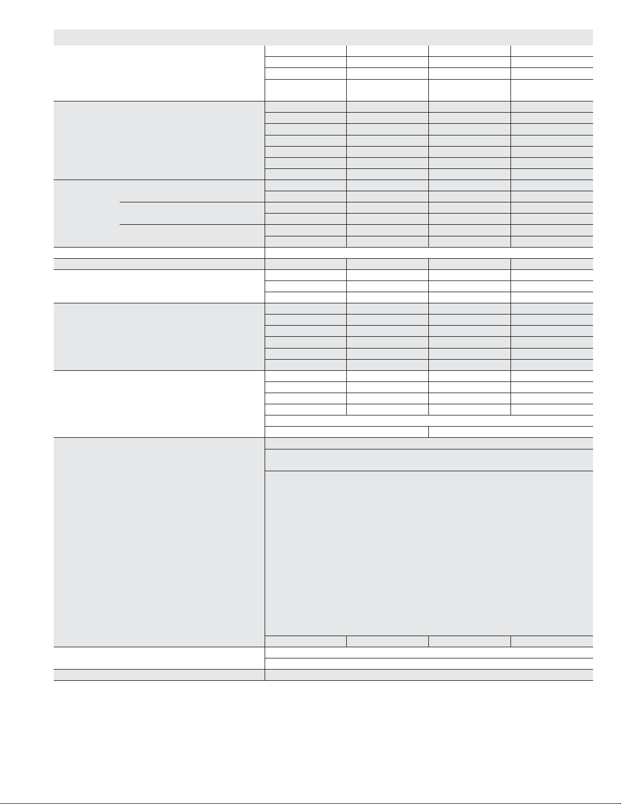
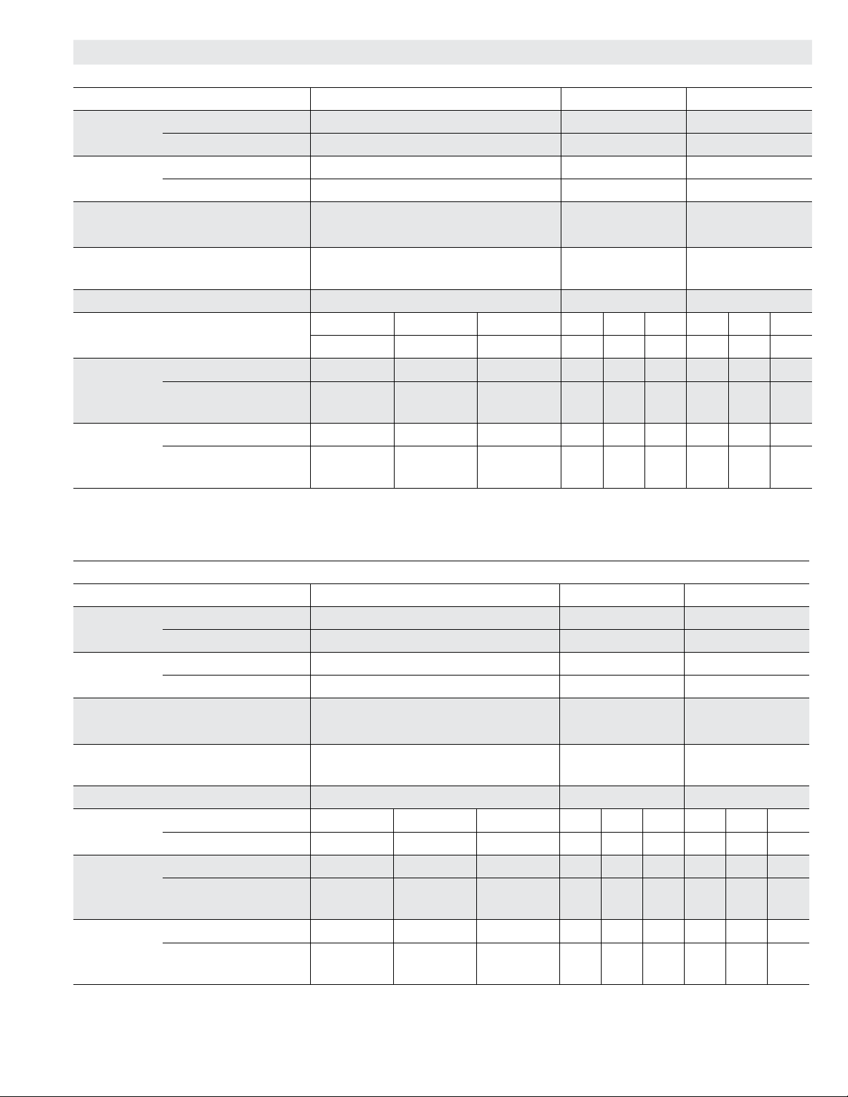
SPECIFICATIONS - 092H, 102H
General Data Nominal Tonnage 7.5 Ton 7.5 Ton 8.5 Ton 8.5 Ton
Model Number LGH092H4B LGH092H4M LGH102H4B LGH102H4M
Efciency Type High High High High
Blower Type Constant Air
Volume CAV
Cooling
Performance
Gross Cooling Capacity - Btuh 93,000 93,000 103,800 103,800
1
Net Cooling Capacity - Btuh 90,000 90,000 100,000 100,000
AHRI Rated Air Flow - cfm 3000 2800 3400 3400
Total Unit Power - kW 7.5 7.5 8.1 8.1
1
EER (Btuh/Watt) 12.5 12.5 12.2 12.2
2
IEER (Btuh/Watt) 13.0 14.0 12.9 14.0
Refrigerant Type R-410A R-410A R-410A R-410A
Refrigerant
Charge
All-Aluminum Coil
System
Conventional Fin/Tube
Coil Option
Conventional Fin/Tube
With Humiditrol
®
Circuit 1 7 lbs. 8 oz. 7 lbs. 8 oz. 7 lbs. 8 oz. 7 lbs. 8 oz.
Circuit 2 7 lbs. 8 oz. 7 lbs. 8 oz. 7 lbs. 8 oz. 7 lbs. 8 oz.
Circuit 1 13 lbs. 8 oz. 13 lbs. 8 oz. 13 lbs. 8 oz. 13 lbs. 8 oz.
Circuit 2 12 lbs. 8 oz. 12 lbs. 8 oz. 12 lbs. 8 oz. 12 lbs. 8 oz.
Circuit 1 17 lbs. 0 oz. 17 lbs. 0 oz. 17 lbs. 0 oz. 17 lbs. 0 oz.
Circuit 2 12 lbs. 8 oz. 12 lbs. 8 oz. 12 lbs. 8 oz. 12 lbs. 8 oz.
Gas Heating Options Available - See page 10 Standard (2 Stage), Medium (2 Stage), High (2 Stage)
Compressor Type (number) Scroll (2) Scroll (2) Scroll (2) Scroll (2)
Outdoor Coils
Aluminum
(Fin/Tube)
Outdoor
Coil Fans
Net face area (total) - sq. ft. 28.0 (29.33) 28.0 (29.33) 28.0 (29.33) 28.0 (29.33)
Number of rows 1 (3) 1 (3) 1 (3) 1 (3)
Fins per inch 20 (20) 20 (20) 20 (20) 20 (20)
Motor - (No.) hp (2) 1/3 (2) 1/3 (2) 1/3 (2) 1/3
Motor rpm 1075 1075 1075 1075
Total Motor watts 800 800 800 800
Diameter - (No.) in. (2) 24 (2) 24 (2) 24 (2) 24
Number of blades 3 3 3 3
Total Air volume - cfm 8800 8800 8800 8800
Indoor
Coils
Net face area (total) - sq. ft. 12.78 12.78 12.78 12.78
Tube diameter - in. 3/8 3/8 3/8 3/8
Number of rows 4 4 4 4
Fins per inch 14 14 14 14
Drain connection - Number and size (1) 1 in. NPT coupling
Expansion device type Balance port TXV, removable head
3
Indoor
Blower and
Drive
Selection
Maximum usable motor output
Blower wheel nominal diameter x
Nominal motor output 2 hp, 3 hp, 5 hp
(US Only)
Motor - Drive kit number 2 hp
(1) 15 X 15 (1) 15 X 15 (1) 15 X 15 (1) 15 X 15
width - in.
Filters Type of lter Disposable
Number and size - in. (4) 20 x 25 x 2
Electrical characteristics 208/230V, 460V or 575V - 60 hertz - 3 phase
NOTE - Net capacity includes evaporator blower motor heat deduction. Gross capacity does not include evaporator blower motor heat deduction.
1
AHRI Certied to AHRI Standard 340/360; 95°F outdoor air temperature and 80°F db/67°F wb entering evaporator air; minimum external duct static pressure.
2
Integrated Energy Efciency Ratio certied and tested according to AHRI Standard 340/360.
3
Using total air volume and system static pressure requirements determine from blower performance tables rpm and motor output required. Maximum usable output of
motors furnished are shown. In Canada, nominal motor output is also maximum usable motor output. If motors of comparable output are used, be sure to keep within
the service factor limitations outlined on the motor nameplate.
NOTE – Units equipped with Multi-Stage Air Volume option are limited to a motor service factor of 1.0.
(Multi-Stage Air
Volume)
Constant Air
Volume CAV
2.3 hp, 3.45 hp, 5.75 hp
Kit 1 590-890 rpm (std. and high efciency)
Kit 2 800-1105 rpm (std. and high efciency)
Kit 3 795-1195 rpm (std. and high efciency)
3 hp
Kit 4 730-970 rpm (std. efciency)
Kit 5 940-1200 rpm (std. efciency)
Kit 6 1015-1300 rpm (std. efciency)
Kit 7 730-970 rpm (high efciency)
Kit 8 940-1200 rpm (high efciency)
Kit 9 1015-1300 rpm (high efciency)
5 hp
Kit 10 900-1135 rpm (std. efciency)
Kit 11 1040-1315 rpm (std. efciency)
Kit 12 1125-1425 rpm (std. efciency)
(Multi-Stage Air
Volume)
Page 8
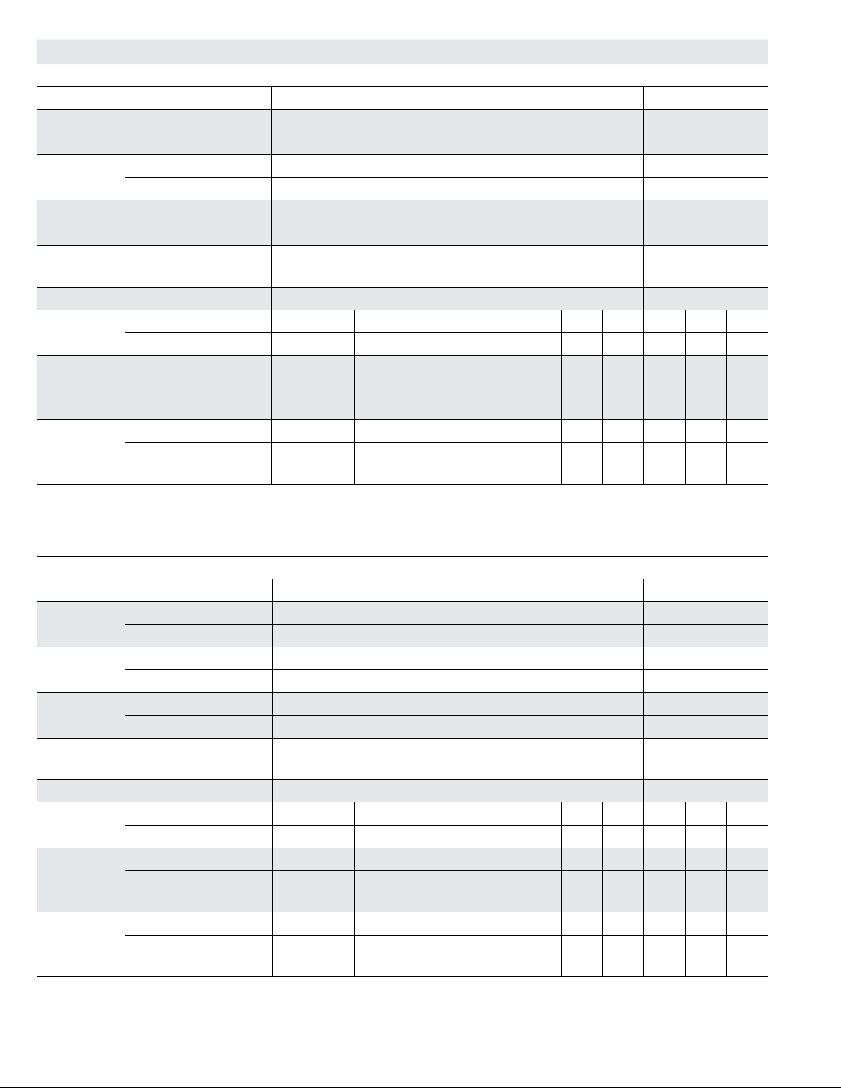
SPECIFICATIONS - 120H, 150S
General Data Nominal Tonnage 10 Ton 10 Ton 12.5 Ton 12.5 Ton
Model Number LGH120H4B LGH120H4M LGH150S4B LGH150S4M
Efciency Type High High Standard Standard
Blower Type Constant Air
Volume CAV
Cooling
Performance
Gross Cooling Capacity - Btuh 122,000 122,000 142,600 142,600
1
Net Cooling Capacity - Btuh 118,000 118,000 138,000 138,000
AHRI Rated Air Flow - cfm 3600 3300 4300 4300
Total Unit Power - kW 9.9 9.8 12.5 12.5
1
EER (Btuh/Watt) 12 12.0 11.0 11.0
2
IEER (Btuh/Watt) 13.0 13.8 11.4 13.1
Refrigerant Type R-410A R-410A R-410A R-410A
Refrigerant
Charge
All-Aluminum Coil
System
Conventional Fin/Tube
Coil Option
Conventional Fin/Tube
With Humiditrol
®
Circuit 1 7 lbs. 4 oz. 7 lbs. 4 oz. 7 lbs. 4 oz. 7 lbs. 4 oz.
Circuit 2 7 lbs. 8 oz. 7 lbs. 8 oz. 6 lbs. 12 oz. 6 lbs. 12 oz.
Circuit 1 14 lbs. 8 oz. 14 lbs. 8 oz. 16 lbs. 8 oz. 16 lbs. 8 oz.
Circuit 2 13 lbs. 8 oz. 13 lbs. 8 oz. 14 lbs. 8 oz. 14 lbs. 8 oz.
Circuit 1 18 lbs. 0 oz. 18 lbs. 0 oz. 18 lbs. 8 oz. 18 lbs. 8 oz.
Circuit 2 13 lbs. 8 oz. 13 lbs. 8 oz. 14 lbs. 8 oz. 14 lbs. 8 oz.
Gas Heating Options Available - See page 10 Standard (2 Stage), Medium (2 Stage), High (2 Stage)
Compressor Type (number) Scroll (2) Scroll (2) Scroll (2) Scroll (2)
Outdoor Coils
Aluminum
(Fin/Tube)
Outdoor
Coil Fans
Net face area (total) - sq. ft. 28.0 (29.33) 28.0 (29.33) 28.0 (29.33) 28.0 (29.33)
Number of rows 1 (3) 1 (3) 1 (3) 1 (3)
Fins per inch 20 (20) 20 (20) 20 (20) 20 (20)
Motor - (No.) hp (2) 1/3 (2) 1/3 (2) 1/2 (2) 1/2
Motor rpm 1075 1075 1075 1075
Total Motor watts 800 800 1050 1050
Diameter - (No.) in. (2) 24 (2) 24 (2) 24 (2) 24
Number of blades 3 3 3 3
Total Air volume - cfm 8800 8800 9700 9700
Indoor
Coils
Net face area (total) - sq. ft. 13.54 13.54 13.54 13.54
Tube diameter - in. 3/8 3/8 3/8 3/8
Number of rows 4 4 4 4
Fins per inch 14 14 14 14
Drain connection - Number and size (1) 1 in. NPT coupling
Expansion device type Balance port TXV, removable head
3
Indoor
Blower and
Drive
Selection
Maximum usable motor output
Nominal motor output 2 hp, 3 hp, 5 hp
(US Only)
Motor - Drive kit number 2 hp
Blower wheel nominal diameter x width - in. (1) 15 X 15 (1) 15 X 15 (1) 15 X 15 (1) 15 X 15
Filters Type of lter Disposable
Number and size - in. (4) 20 x 25 x 2
Electrical characteristics 208/230V, 460V or 575V - 60 hertz - 3 phase
NOTE - Net capacity includes evaporator blower motor heat deduction. Gross capacity does not include evaporator blower motor heat deduction.
1
AHRI Certied to AHRI Standard 340/360; 95°F outdoor air temperature and 80°F db/67°F wb entering evaporator air; minimum external duct static pressure.
2
Integrated Energy Efciency Ratio certied and tested according to AHRI Standard 340/360.
3
Using total air volume and system static pressure requirements determine from blower performance tables rpm and motor output required. Maximum usable output of
motors furnished are shown. In Canada, nominal motor output is also maximum usable motor output. If motors of comparable output are used, be sure to keep within
the service factor limitations outlined on the motor nameplate.
5
150 models ordered with the Humiditrol® Dehumidication option are equipped with factory installed expansion valves.
NOTE – Units equipped with Multi-Stage Air Volume option are limited to a motor service factor of 1.0.
Multi-Stage Air
Volume
Constant Air
Volume CAV
5
Refrigerant Metering Orice (RFC)
2.3 hp, 3.45 hp, 5.75 hp
Kit 1 590-890 rpm (std. and high efciency)
Kit 2 800-1105 rpm (std. and high efciency)
Kit 3 795-1195 rpm (std. and high efciency)
3 hp
Kit 4 730-970 rpm (std. efciency)
Kit 5 940-1200 rpm (std. efciency)
Kit 6 1015-1300 rpm (std. efciency)
Kit 7 730-970 rpm (high efciency)
Kit 8 940-1200 rpm (high efciency)
Kit 9 1015-1300 rpm (high efciency)
5 hp
Kit 10 900-1135 rpm (std. efciency)
Kit 11 1040-1315 rpm (std. efciency)
Kit 12 1125-1425 rpm (std. efciency)
Multi-Stage Air
Volume
Page 9
SPECIFICATIONS - GAS HEAT - 092H, 102H, 120H, 150S
Heat Input Type Standard Medium High
Number of Gas Heat Stages 2 2 2
Gas Heating
Performance
Recommended Gas Supply
Pressure - in. w.g.
Input - Btuh First Stage 84,500 117,000 156,000
Second Stage 130,000 180,000 240,000
Output - Btuh Second Stage 104,000 144,000 192,000
Temperature Rise Range - °F 15 - 45 30 - 60 40 - 70
Thermal Efciency 80% 80% 80%
Gas Supply Connections 3/4 in. npt 3/4 in. npt 3/4 in. npt.
Natural 7 in. w.c. 7 in. w.c. 7 in. w.c.
LPG/Propane 11 in. w.c. 11 in. w.c. 11 in. w.c.
HIGH ALTITUDE DERATE - 092H, 102H, 120H, 150S
Units may be installed at altitudes up to 2000 feet above sea level without any modication.
At altitudes above 2000 feet, units must be derated to match gas manifold pressures shown in table below.
At altitudes above 4500 feet unit must be derated 2% for each 1000 feet above sea level.
NOTE − This is the only permissible derate for these units.
Gas Heat
Type
Standard 2001-4500 3.4 9.6 84,500 124,000
Medium 2001-4500 3.4 9.6 117,000 172,000
High 2001-4500 3.4 9.6 156,000 230,000
Altitude
Feet
Gas Manifold Pressure
in. w.g.
Natural Gas LPG/Propane Gas First Stage Second Stage
Input Rate - Btuh
(Natural Gas or LPG/Propane)
Page 10
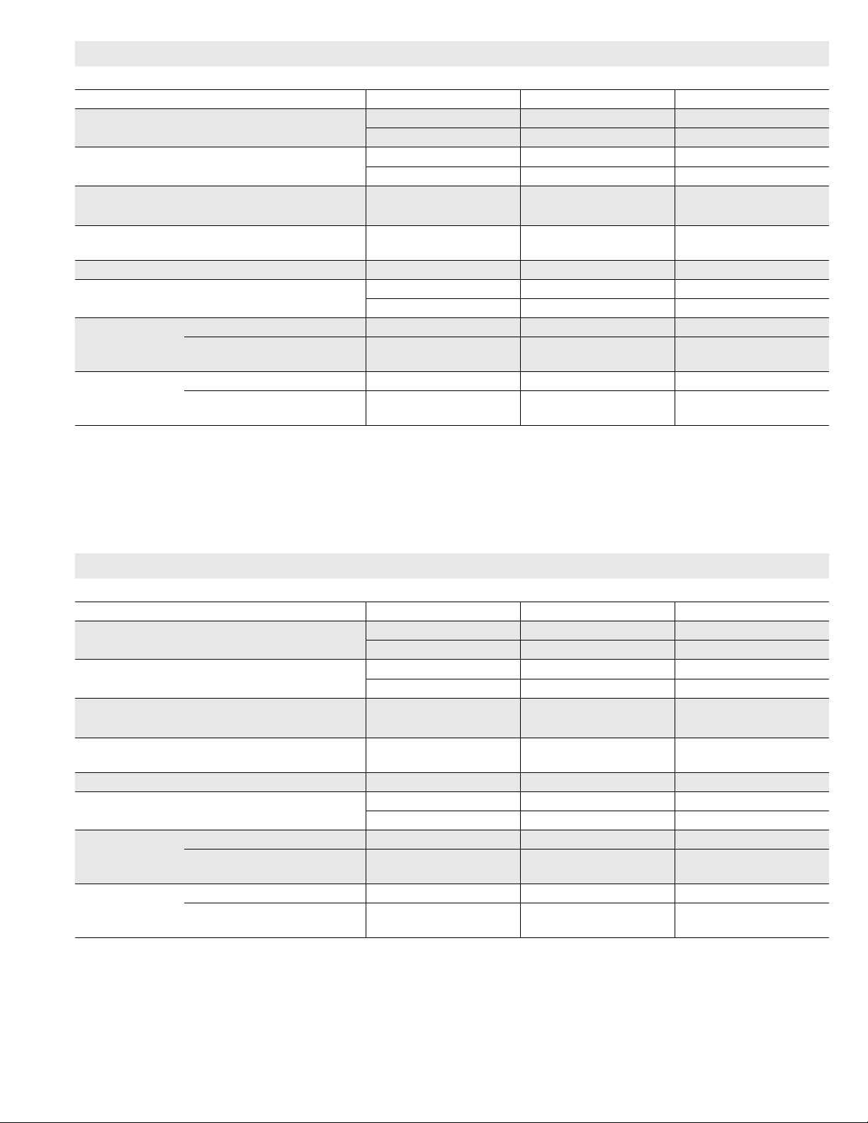
SPECIFICATIONS - DIRECT DRIVE MODELS
General Data Nominal Tonnage 7.5 Ton 10 Ton 12.5 Ton
Model Number LGH094U4E LGH122U4E LGH152U4E
Efciency Type Ultra Ultra Ultra
Blower Type Direct Drive Direct Drive Direct Drive
Cooling
Performance
Gross Cooling Capacity - Btuh 93,700 119,000 141,900
1
Net Cooling Capacity - Btuh 92,000 116,000 138,000
AHRI Rated Air Flow - cfm 2800 3600 4000
Total Unit Power - kW 6.6 8.8 11.2
1
EER (Btuh/Watt) 13.9 13.1 12.3
2
IEER (Btuh/Watt) 21.5 20.0 18.9
Refrigerant Type R-410A R-410A R-410A
Refrigerant Charge Circuit 1 29 lbs. 0 oz. 29 lbs. 0 oz. 29 lbs. 0 oz.
Gas Heating Options Available - See page 7 Standard (2 Stage), Medium (2 Stage), High (2 Stage)
Compressor Type (number) Tandem Scroll (2) Tandem Scroll (2) Tandem Scroll (2)
Outdoor Coils Net face area (total) - sq. ft. 40.8 40.8 40.8
Number of rows 2 2 2
Fins per inch 20 20 20
Outdoor
Coil Fans
Motor - (No.) hp (3) 1/3 ECM (3) 1/3 ECM (3) 1/3 ECM
Motor rpm 520 - 900 640 - 900 640 - 900
Total Motor watts 160 - 650 280 - 650 280 - 650
Diameter - (No.) in. (3) 24 (3) 24 (3) 24
Number of blades 3 3 3
Total Air volume - cfm 5160 - 10,250 7100 - 10,250 7100 - 10,250
Indoor
Coil
Net face area (total) - sq. ft. 13.54 13.54 13.54
Tube diameter - in. 3/8 3/8 3/8
Number of rows 4 4 4
Fins per inch 14 14 14
Drain connection - Number and size (1) 1 in. NPT coupling
Expansion device type Dual-Flow Thermal Expansion Valve System Dual with Flow Control
Balance port, removable head
Indoor
Blower
Blower wheel nominal diameter x width - in. (1) 22 x 9 (1) 22 x 9 (1) 22 x 9
Nominal motor output 3.75 HP (ECM) 3.75 HP (ECM) 3.75 HP (ECM)
Filters Type of lter Disposable
Number and size - in. (4) 20 x 25 x 2
Electrical characteristics 208/230V, 460V or 575V - 60 hertz - 3 phase
NOTE - Net capacity includes evaporator blower motor heat deduction. Gross capacity does not include evaporator blower motor heat deduction.
1
AHRI Certied to AHRI Standard 340/360; 95°F outdoor air temperature and 80°F db/67°F wb entering evaporator air; minimum external duct static pressure.
2
Integrated Energy Efciency Ratio certied and tested according to AHRI Standard 340/360.
Page 11
SPECIFICATIONS - BELT DRIVE MODELS - 094U, 122U, 152U
General Data Nominal Tonnage 7.5 Ton 10 Ton 12.5 Ton
Model Number LGH094U4M LGH122U4M LGH152U4M
Efciency Type Ultra Ultra Ultra
Blower Type
Belt Drive
Cooling
Performance
Gross Cooling Capacity - Btuh 93,700 119,000 141,900
1
Net Cooling Capacity - Btuh 92,000 116,000 136,000
AHRI Rated Air Flow - cfm 2800 3600 4000
Total Unit Power - kW 6.9 8.8 11.5
1
EER (Btuh/Watt) 13.4 12.6 12.0
2
IEER (Btuh/Watt) 20.7 19.2 18.1
Refrigerant Type R-410A R-410A R-410A
Refrigerant Charge Circuit 1 29 lbs. 0 oz. 29 lbs. 0 oz. 29 lbs. 0 oz.
Gas Heating Options Available - See page 7 Standard (2 Stage), Medium (2 Stage), High (2 Stage)
Compressor Type (number) Tandem Scroll (2) Tandem Scroll (2) Tandem Scroll (2)
Outdoor Coils Net face area (total) - sq. ft. 40.8 40.8 40.8
Number of rows 2 2 2
Fins per inch 20 20 20
Outdoor
Coil Fans
Motor - (No.) hp (3) 1/3 ECM (3) 1/3 ECM (3) 1/3 ECM
Motor rpm 520 - 900 640 - 900 640 - 900
Total Motor watts 160 - 650 280 - 650 280 - 650
Diameter - (No.) in. (3) 24 (3) 24 (3) 24
Number of blades 3 3 3
Total Air volume - cfm 5160 - 10,250 7100 - 10,250 7100 - 10,250
Indoor
Coil
Net face area (total) - sq. ft. 13.54 13.54 13.54
Tube diameter - in. 3/8 3/8 3/8
Number of rows 4 4 4
Fins per inch 14 14 14
Drain connection - Number and size (1) 1 in. NPT coupling
Expansion device type Dual-Flow Thermal Expansion Valve System Dual with Flow Control
Balance port, removable head
3
Indoor
Blower
and Drive
Selection
Nominal motor output 2 hp, 3 hp, 5 hp
Motor - Drive kit number 2 hp
Kit 1 590-890 rpm (std. and high efciency)
Kit 2 800-1105 rpm (std. and high efciency)
Kit 3 795-1195 rpm (std. and high efciency)
Kit 4 730-970 rpm (std. efciency)
Kit 5 940-1200 rpm (std. efciency)
Kit 6 1015-1300 rpm (std. efciency)
Kit 7 730-970 rpm (high efciency)
Kit 8 940-1200 rpm (high efciency)
Kit 9 1015-1300 rpm (high efciency)
Kit 10 900-1135 rpm (std. efciency)
Kit 11 1040-1315 rpm (std. efciency)
Kit 12 1125-1425 rpm (std. efciency)
Blower wheel nominal diameter x width - in. (1) 15 X 15 (1) 15 X 15 (1) 15 X 15
Filters Type of lter Disposable
Number and size - in. (4) 20 x 25 x 2
Electrical characteristics 208/230V, 460V or 575V - 60 hertz - 3 phase
NOTE - Net capacity includes evaporator blower motor heat deduction. Gross capacity does not include evaporator blower motor heat deduction.
1
AHRI Certied to AHRI Standard 340/360; 95°F outdoor air temperature and 80°F db/67°F wb entering evaporator air; minimum external duct static pressure.
2
Integrated Energy Efciency Ratio certied and tested according to AHRI Standard 340/360.
3
Using total air volume and system static pressure requirements determine from blower performance tables rpm and motor output required. Maximum usable output of
motors furnished are shown. If motors of comparable output are used, be sure to keep within the service factor limitations outlined on the motor nameplate.
Belt Drive
3 hp
5 hp
Belt Drive
Page 12

SPECIFICATIONS - GAS HEAT - 094U, 122U, 152U
Heat Input Type Standard Medium High
Number of Gas Heat Stages 2 2 2
Gas Heating
Performance
Recommended Gas Supply
Pressure - in. w.g.
Input - Btuh First Stage 84,500 117,000 156,000
Second Stage 130,000 180,000 240,000
Output - Btuh Second Stage 104,000 144,000 192,000
Temperature Rise Range - °F 15 - 45 30 - 60 40 - 70
Thermal Efciency 80% 80% 80%
Gas Supply Connections 3/4 in. npt 3/4 in. npt 3/4 in. npt.
Natural 7 in. w.c. 7 in. w.c. 7 in. w.c.
LPG/Propane 11 in. w.c. 11 in. w.c. 11 in. w.c.
Page 13
BLOWER DATA
092, 094, AND 102 BELT DRIVE BLOWER − BASE UNIT
BLOWER TABLE INCLUDES RESISTANCE FOR BASE UNIT ONLY (NO HEAT SECTION) WITH DRY INDOOR COIL AND AIR
FILTERS IN PLACE.
FOR ALL UNITS ADD:
1 − Wet indoor coil air resistance of selected unit.
2 − Any factory installed options air resistance (heat section, economizer, etc.)
3 − Any eld installed accessories air resistance (duct resistance, diffuser, etc.)
Then determine from blower table blower motor output required.
See page 16 for blower motors and drives. See page 16 for wet coil and option/accessory air resistance data.
MAXIMUM STATIC PRESSURE WITH GAS HEAT - 2.0 in. w.g.
Total
Air
Volume
cfm
1750 481 0.21 549 0.4 618 0.57 688 0.7 758 0.82 824 0.93 885 1.08 941 1.23 991 1.39 1038 1.54 1082 1.68 1124 1.82 1166 1.95
2000 493 0.29 561 0.47 629 0.64 700 0.77 768 0.9 832 1.02 892 1.17 946 1.33 995 1.49 1041 1.66 1085 1.81 1126 1.97 1167 2.12
2250 507 0.37 574 0.56 643 0.72 712 0.86 779 0.99 842 1.13 900 1.28 953 1.44 1001 1.61 1045 1.78 1088 1.95 1128 2.12 1168 2.3
2500 521 0.46 588 0.64 657 0.81 727 0.95 792 1.09 853 1.24 909 1.4 960 1.57 1007 1.74 1050 1.93 1091 2.11 1130 2.29 1170 2.48
2750 537 0.56 604 0.74 674 0.91 743 1.06 806 1.21 865 1.36 920 1.53 969 1.71 1014 1.89 1055 2.08 1095 2.27 1133 2.47 1172 2.66
3000 554 0.67 622 0.86 692 1.02 760 1.18 822 1.34 878 1.5 931 1.68 979 1.86 1021 2.06 1061 2.26 1099 2.46 1136 2.65 1174 2.85
3250 572 0.78 641 0.98 712 1.15 778 1.32 838 1.49 892 1.66 943 1.84 989 2.03 1030 2.24 1068 2.45 1105 2.65 1141 2.85 1178 3.06
3500 592 0.9 663 1.12 733 1.3 798 1.47 855 1.65 907 1.83 956 2.02 1000 2.22 1039 2.44 1076 2.65 1111 2.86 1146 3.07 1183 3.27
3750 614 1.04 687 1.28 756 1.47 818 1.65 872 1.83 923 2.02 970 2.22 1011 2.43 1049 2.65 1084 2.87 1118 3.09 1152 3.29 1189 3.51
4000 639 1.22 713 1.48 780 1.66 838 1.83 890 2.02 939 2.22 984 2.44 1023 2.66 1059 2.89 1093 3.11 1126 3.33 1160 3.54 1197 3.77
4250 667 1.43 741 1.69 805 1.86 859 2.02 909 2.22 956 2.45 998 2.68 1036 2.92 1070 3.15 1103 3.37 1135 3.59 1169 3.81 1207 4.05
0.2 0.4 0.6 0.8 1.0 1.2 1.4 1.6 1.8 2.0 2.2 2.4 2.6
RPM BHP RPM BHP RPM BHP RPM BHP RPM BHP RPM BHP RPM BHP RPM BHP RPM BHP RPM BHP RPM BHP RPM BHP RPM BHP
Total Static Pressure − in. w.g.
Page 14
BLOWER DATA
120, 122, 150 AND 152 BELT DRIVE BLOWER − BASE UNIT
BLOWER TABLE INCLUDES RESISTANCE FOR BASE UNIT ONLY (NO HEAT SECTION) WITH DRY INDOOR COIL AND AIR
FILTERS IN PLACE.
FOR ALL UNITS ADD:
1 − Wet indoor coil air resistance of selected unit.
2 − Any factory installed options air resistance (heat section, economizer, etc.)
3 − Any eld installed accessories air resistance (duct resistance, diffuser, etc.)
Then determine from blower table blower motor output required.
See page 16 for blower motors and drives. See page 16 for wet coil and option/accessory air resistance data.
MAXIMUM STATIC PRESSURE WITH GAS HEAT - 2.0 in. w.g.
Total
Air
Volume
cfm
2000 497 0.25 558 0.44 624 0.6 694 0.74 764 0.85 830 0.99 889 1.16 943 1.34 994 1.52 1045 1.71 1096 1.89 1146 2.08 1197 2.27
2250 511 0.34 573 0.52 638 0.68 708 0.82 776 0.94 839 1.09 896 1.26 948 1.45 998 1.64 1048 1.83 1098 2.01 1149 2.2 1200 2.4
2500 527 0.44 589 0.62 654 0.78 723 0.91 789 1.05 850 1.21 904 1.39 955 1.58 1003 1.77 1052 1.96 1101 2.14 1152 2.33 1203 2.53
2750 545 0.55 606 0.72 672 0.88 740 1.03 804 1.17 861 1.34 914 1.53 962 1.72 1010 1.92 1057 2.10 1105 2.29 1154 2.47 1206 2.68
3000 564 0.66 626 0.84 692 1.01 759 1.16 819 1.32 874 1.49 924 1.68 971 1.88 1017 2.08 1063 2.26 111 0 2.44 1158 2.63 1208 2.83
3250 585 0.79 648 0.98 714 1.14 778 1.31 836 1.48 887 1.66 935 1.86 981 2.06 1026 2.26 1071 2.45 111 7 2.63 1163 2.80 1213 3.00
3500 607 0.93 672 1.13 737 1.31 798 1.48 852 1.66 901 1.85 948 2.05 993 2.26 1037 2.46 1081 2.65 1125 2.83 1171 3.01 1221 3.21
3750 632 1.10 698 1.31 762 1.50 819 1.67 869 1.86 915 2.05 961 2.25 1005 2.47 1049 2.68 1092 2.88 1136 3.05 1181 3.24 1231 3.45
4000 660 1.30 726 1.52 787 1.70 838 1.87 885 2.06 930 2.26 974 2.48 1018 2.71 1062 2.93 1105 3.12 1149 3.30 1194 3.49 1245 3.72
4250 691 1.53 755 1.75 810 1.91 857 2.07 901 2.27 945 2.50 990 2.74 1034 2.98 1077 3.20 1120 3.39 1163 3.58 1210 3.79 1262 4.03
4500 724 1.78 783 1.98 831 2.12 874 2.28 917 2.50 962 2.75 1006 3.02 1051 3.27 1094 3.49 1137 3.70 1181 3.89 1228 4.11 1281 4.38
4750 757 2.05 809 2.20 851 2.33 891 2.51 935 2.76 980 3.05 1025 3.33 1070 3.59 1113 3.82 1156 4.03 1201 4.24 1249 4.47 1303 4.75
0.2 0.4 0.6 0.8 1.0 1.2 1.4 1.6 1.8 2.0 2.2 2.4 2.6
RPM BHP RPM BHP RPM BHP RPM BHP RPM BHP RPM BHP RPM BHP RPM BHP RPM BHP RPM BHP RPM BHP RPM BHP RPM BHP
Total Static Pressure − in. w.g.
5000 787 2.31 831 2.43 870 2.57 910 2.78 954 3.06 1000 3.38 1046 3.68 1091 3.95 1
5250 814 2.55 852 2.66 889 2.83 930 3.09 975 3.41 1023 3.76 1070 4.08 1115 4.35 1159 4.59 1203 4.81 1248 5.03 1297 5.27 1350 5.53
5500 835 2.78 871 2.91 909 3.13 952 3.44 999 3.81 1049 4.18 1096 4.51 1142 4.79 1186 5.03 1229 5.24 1275 5.46 1324 5.69 - - - - - -
5750 854 3.01 890 3.19 930 3.48 977 3.86 1027 4.27 1078 4.66 1126 4.99 1171 5.26 1214 5.49 1258 5.70 - - - - - - - - - - - - - - - - - -
6000 871 3.26 910 3.53 955 3.90 1006 4.34 1060 4.80 1111 5.19 1158 5.51 - - - - - - - - - - - - - - - - - - - - - - - - - - - - - - - - - - - -
6250 890 3.57 934 3.94 985 4.41 1041 4.91 1096 5.38 - - - - - - - - - - - - - - - - - - - - - - - - - - - - - - - - - - - - - - - - - - - - - - - -
135 4.19 1178 4.40 1224 4.62 1272 4.86 1325 5.13
Page 15
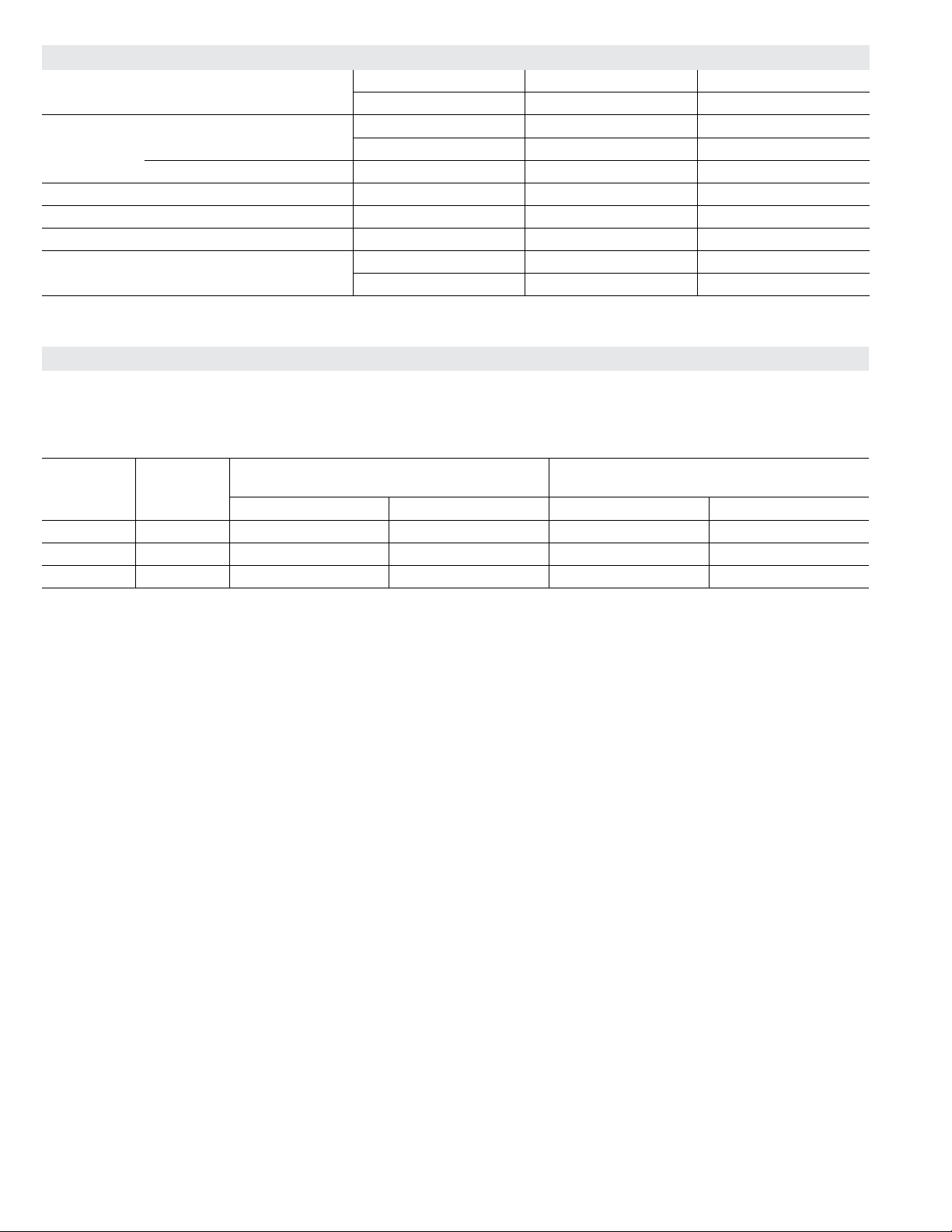
BLOWER DATA - 092, 094, 102, 120, 122, 150, 152
FACTORY INSTALLED BELT DRIVE KIT SPECIFICATIONS
Motor Efciency Nominal hp Maximum hp Drive Kit Number RPM Range
Standard & High 2 2.3 1 590 - 890
Standard & High 2 2.3 2 800 - 1105
Standard & High 2 2.3 3 795 - 1195
Standard 3 3.45 4 730 - 970
Standard 3 3.45 5 940 - 1200
Standard 3 3.45 6 1015 - 1300
High 3 3.45 7 730 - 970
High 3 3.45 8 940 - 1200
High 3 3.45 9 1015 - 1300
Standard 5 5.75 10 900 - 1135
Standard 5 5.75 11 1040 - 1315
Standard 5 5.75 12 1125 - 1425
NOTE - Using total air volume and system static pressure requirements determine from blower performance tables rpm and motor output required. Maximum usable
output of motors furnished are shown. In Canada, nominal motor output is also maximum usable motor output. If motors of comparable output are used, be sure to keep
within the service factor limitations outlined on the motor nameplate.
NOTE – Units equipped with Multi-Stage Air Volume option are limited to a motor service factor of 1.0.
POWER EXHAUST FAN PERFORMANCE
Return Air System Static Pressure Air Volume Exhausted
in. w.g. cfm
0 3175
0.05 2955
0.10 2685
0.15 2410
0.20 2165
0.25 1920
0.30 1420
0.35 1200
FACTORY INSTALLED OPTIONS/FIELD INSTALLED ACCESSORY AIR RESISTANCE - in. w.g.
Air
Volume
cfm
Wet Indoor Coil
Gas Heat Exchanger
Standard
Heat
Medium
heat
High
Heat
Economizer
Humiditrol
Condenser
Reheat Coil
Filters
MERV 8 MERV 13
Return Air
Adaptor Plate
092, 102 120, 150
1750 0.04 0.04 0.06 0.02 0.02 0.05 0.02 0.01 0.03 0.00
2000 0.05 0.05 0.07 0.05 0.06 0.06 0.02 0.01 0.03 0.00
2250 0.06 0.06 0.07 0.07 0.08 0.08 0.02 0.01 0.04 0.00
2500 0.07 0.07 0.09 0.10 0.11 0.11 0.03 0.01 0.05 0.00
2750 0.08 0.08 0.09 0.11 0.12 0.12 0.03 0.02 0.05 0.00
3000 0.10 0.09 0.11 0.12 0.13 0.13 0.03 0.02 0.06 0.02
3250 0.11 0.10 0.12 0.15 0.16 0.15 0.04 0.02 0.06 0.02
3500 0.12 0.11 0.12 0.16 0.17 0.15 0.04 0.03 0.07 0.04
3750 0.14 0.13 0.14 0.19 0.20 0.15 0.05 0.03 0.08 0.07
4000 0.15 0.14 0.14 0.21 0.22 0.19 0.05 0.04 0.08 0.09
4250 0.17 0.15 0.14 0.24 0.28 0.19 0.06 0.04 0.09 0.11
4500 0.19 0.17 0.15 0.26 0.32 0.22 0.07 0.04 0.09 0.12
4750 0.20 0.18 0.16 0.29 0.37 0.25 0.07 0.05 0.10 0.16
5000 0.22 0.20 0.16 0.34 0.43 0.29 0.08 0.06 0.10 0.18
5250 0.24 0.22 0.16 0.37 0.47 0.32 0.08 0.06 0.11 0.19
5500 0.25 0.23 0.18 0.44 0.54 0.34 0.09 0.07 0.12 0.22
5750 0.27 0.25 0.19 0.49 0.59 0.45 0.10 0.07 0.12 0.25
6000 0.29 0.27 0.20 0.54 0.64 0.52 0.10 0.08 0.13 0.27
Page 16
BLOWER DATA
CEILING DIFFUSERS AIR RESISTANCE - in. w.g.
Unit Size
092, 094 Models
102, 120 & 122
Models
150, 152 Models
Air Volume
cfm
2 Ends Open
2400 0.21 0.18 0.15 0.14
2600 0.24 0.21 0.18 0.17
2800 0.27 0.24 0.21 0.20
3000 0.32 0.29 0.25 0.25
3200 0.41 0.37 0.32 0.31
3400 0.50 0.45 0.39 0.37
3600 0.61 0.54 0.48 0.44
3800 0.73 0.63 0.57 0.51
3600 0.36 0.28 0.23 0.15
3800 0.40 0.32 0.26 0.18
4000 0.44 0.36 0.29 0.21
4200 0.49 0.40 0.33 0.24
4400 0.54 0.44 0.37 0.27
4600 0.60 0.49 0.42 0.31
4800 0.65 0.53 0.46 0.35
5000 0.69 0.58 0.50 0.39
5200 0.75 0.62 0.54 0.43
4200 0.22 0.19 0.16 0.10
4400 0.28 0.24 0.20 0.12
4600 0.34 0.29 0.24 0.15
4800 0.40 0.34 0.29 0.19
5000 0.46 0.39 0.34 0.23
5200 0.52 0.44 0.39 0.27
5400 0.58 0.49 0.43 0.31
5600 0.64 0.54 0.47 0.35
5800 0.70 0.59 0.51 0.39
RTD11 Step-Down Diffuser
1 Side, 2 Ends
Open
All Ends & Sides
Open
FD11 Flush
Diffuser
CEILING DIFFUSER AIR THROW DATA
1
Effective Throw Range
RTD11 Step-Down FD11 Flush
Model No.
Air Volume
cfm ft. ft.
2600 24 - 29 19 - 24
2800 25 - 30 20 - 28
092, 094
Models
3000 27 - 33 21 - 29
3200 28 - 35 22 - 29
3400 30 - 37 22 - 30
3600 25 - 33 22 - 29
3800 27 - 35 22 - 30
102, 120, 122
Models
4000 29- 37 24 - 33
4200 32 - 40 26 - 35
4400 34 - 42 28 - 37
5600 39 - 49 28 - 37
5800 42 - 51 29 - 38
150, 152
Models
6000 44 - 54 40 - 50
6200 45 - 55 42 - 51
6400 46 - 55 43 - 52
6600 47 - 56 45 - 56
1
Throw is the horizontal or vertical distance an air stream travels on leaving the outlet or diffuser
before the maximum velocity is reduced to 50 ft. per minute. Four sides open.
Page 17
BLOWER DATA - DIRECT DRIVE - 094U, 122U, 152U
BLOWER TABLE INCLUDES RESISTANCE FOR BASE UNIT ONLY (NO HEAT SECTION) WITH DRY INDOOR COIL AND AIR
FILTERS IN PLACE.
FOR ALL UNITS ADD:
1 − Wet indoor coil air resistance of selected unit.
2 − Any factory installed options air resistance (heat section, economizer, etc.)
3 − Any eld installed accessories air resistance (duct resistance, diffuser, etc.)
See page 21 for wet coil and option/accessory air resistance data.
MAXIMUM STATIC PRESSURE WITH GAS HEAT - 2.0 in. w.g.
Total
Air Volume
cfm
1750 7 11 188 771 279 836 366 905 453 975 544 1044 640 1109 737
2000 752 242 812 332 876 420 944 510 1011 606 1075 709 1138 812
2250 799 300 860 389 923 479 988 575 1052 678 1113 787 1171 896
2500 853 362 914 453 976 548 1038 650 1097 761 1154 877 1209 990
2750 914 434 974 529 1033 629 1091 739 1146 858 1199 979 1250 1098
3000 980 513 1037 614 1092 720 1146 837 1198 961 1247 1088 1295 1215
3250 1048 598 1101 705 1153 819 1203 941 1251 1071 1298 1206 1343 1343
3500 1116 693 1166 809 1214 931 1261 1060 1307 1198 1351 1341 1395 1489
3750 1185 806 1232 931 1277 1063 1322 1201 1365 1348 1407 1499 1448 1657
4000 1254 937 1299 1072 1341 1214 1383 1363 1424 1518 1464 1679 1503 1844
4250 1324 1089 1366 1234 1406 1386 1445 1545 1484 1708 1522 1876 1559 2046
4500 1395 1262 1433 1417 1471 1579 1508 1745 1544 1913 1581 2084 1616 2256
4750 1465 1455 1501 1619 1536 1787 1571 1957 1606 2128 1641 2299 1675 2470
5000 1534 1666 1568 1834 1602 2004 1635 2174 1668 2345 1701 2514 1735 2682
5250 1603 1887 1635 2055 1667 2224 1699 2392 1731 2559 1763 2724 - - - - - -
5500 1671 2110 1702 2275 1733 2441 1764 2605 - - - - - - - - - - - - - - - - - -
5750 1738 2325 1768 2488 - - - - - - - - - - - - - - - - - - - - - - - - - - - - - -
Total
Air Volume
cfm
1750 1172 833 1231 932 1287 1039 1340 1156 1391 1283 1442 1426
2000 1197 913 1253 1019 1306 1135 1357 1261 1407 1398 1457 1547
2250 1227 1003 1280 1117 1330 1242 1379 1378 1428 1525 1477 1680
2500 1261 1103 1311 1226 1360 1361 1407 1507 1454 1663 1501 1826
2750 1299 1219 1347 1350 1394 1494 1440 1649 1485 1813 1530 1982
3000 1342 1346 1388 1487 1432 1640 1476 1803 1520 1973 1563 2146
3250 1388 1485 1432
3500 1437 1643 1479 1805 1519 1975 1560 2148 1600 2325 1640 2502
3750 1489 1821 1528 1990 1567 2164 1605 2340 1645 2517 1685 2693
4000 1541 2014 1579 2187 1616 2364 1654 2540 1693 2715 1732 2887
4250 1596 2218 1632 2393 1668 2569 1705 2742 1743 2913 - - - - - -
4500 1652 2429 1687 2603 1722 2775 1759 2944 - - - - - - - - - - - -
4750 1709 2641 1743 281
5000 1768 2850 - - - - - - - - - - - - - - - - - - - - - - - - - - - - - -
5250 - - - - - - - - - - - - - - - - - - - - - - - - - - - - - - - - - - - -
5500 - - - - - - - - - - - - - - - - - - - - - - - - - - - - - - - - - - - -
5750 - - - - - - - - - - - - - - - - - - - - - - - - - - - - - - - - - - - -
0.2 0.4 0.6 0.8 1.0 1.2 1.4
RPM Watts RPM Watts RPM Watts RPM Watts RPM Watts RPM Watts RPM Watts
1.6 1.8 2.0 2.2 2.4 2.6
RPM Watts RPM Watts RPM Watts RPM Watts RPM Watts RPM Watts
1638 1475 1800 1517 1969 1558 2143 1600 2319
1 1778 2979 - - - - - - - - - - - - - - - - - -
Total Static Pressure - in. w.g.
Total Static Pressure - in. w.g.
Page 18
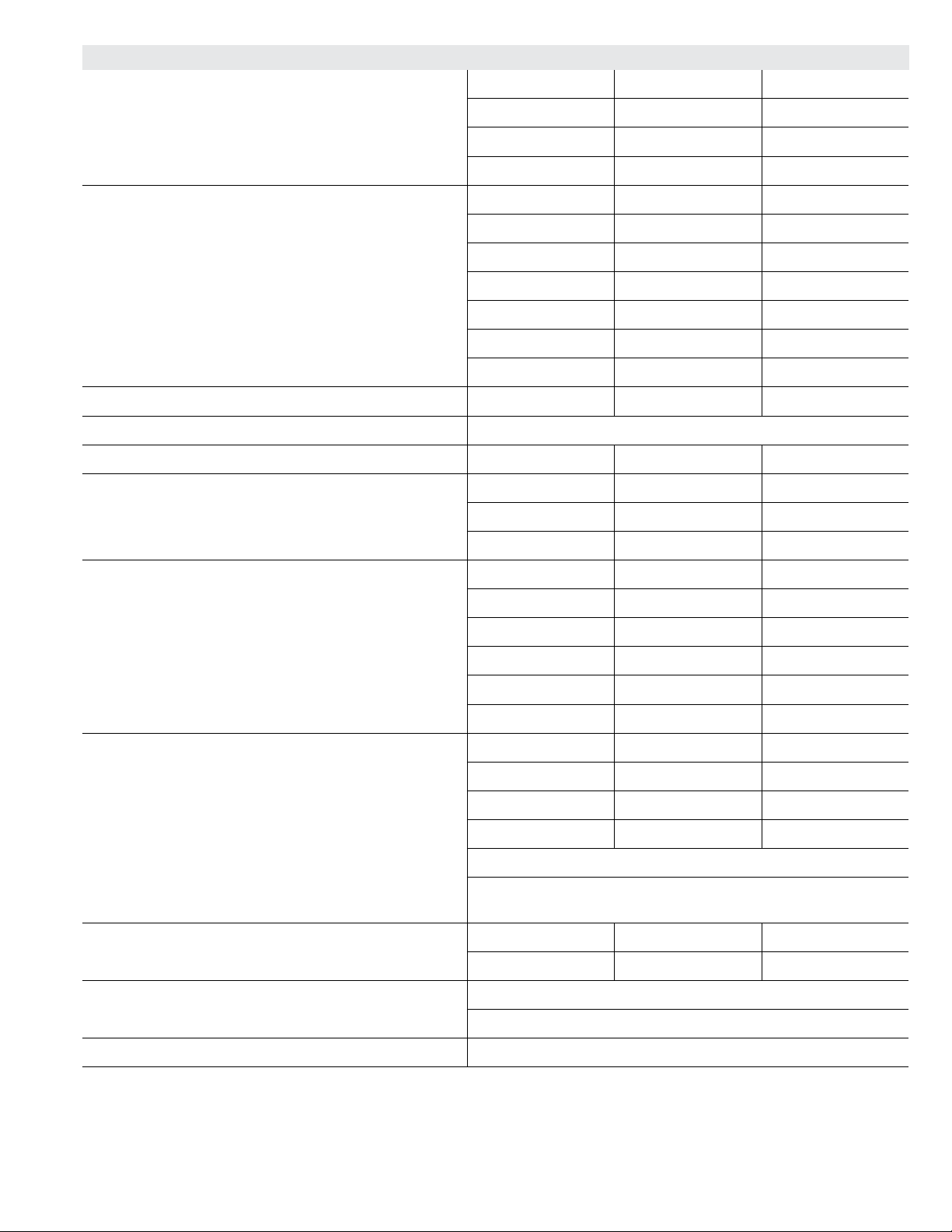
ELECTRICAL DATA
7.5 TON HIGH EFFICIENCY (R-410A) LGH092H4
1
Voltage - 60hz 208/230V - 3 Ph 460V - 3 Ph 575V - 3 Ph
Compressor 1 Rated Load Amps 13.1 6.1 4.4
Locked Rotor Amps 83.1 41 33
Compressor 2 Rated Load Amps 13.1 6.1 4.4
Locked Rotor Amps 83.1 41 33
Outdoor Fan
Motors (2)
Power Exhaust
(1) 0.33 HP
Service Outlet 115V GFI (amps) 15 15 20
Indoor Blower
Motor
2
Maximum
Overcurrent
Protection
3
Minimum
Circuit
Ampacity
NOTE - All units have a minimum Short Circuit Current Rating (SCCR) of 5000 amps.
1
Extremes of operating range are plus and minus 10% of line voltage.
2
HACR type breaker or fuse.
3
Refer to National or Canadian Electrical Code manual to determine wire, fuse and disconnect size requirements.
Full Load Amps 2.4 1.3 1
(total) (4.8) (2.6) (2)
Full Load Amps 2.4 1.3 1
Horsepower 2 3 5 2 3 5 2 3 5
Full Load Amps 7.5 10.6 16.7 3.4 4.8 7.6 2.7 3.9 6.1
Unit Only 50 50 60 25 25 30 15 20 20
With (1) 0.33 HP
50 60 70 25 25 30 20 20 25
Power Exhaust
Unit Only 42 45 52 20 22 25 15 16 19
With (1) 0.33 HP
45 48 55 22 23 26 16 17 20
Power Exhaust
8.5 TON HIGH EFFICIENCY (R-410A) LGH102H4
1
Voltage - 60hz 208/230V - 3 Ph 460V - 3 Ph 575V - 3 Ph
Compressor 1 Rated Load Amps 13.7 6.2 4.8
Locked Rotor Amps 83.1 41 33
Compressor 2 Rated Load Amps 13.7 6.2 4.8
Locked Rotor Amps 83.1 41 33
Outdoor Fan
Motors (2)
Power Exhaust
Full Load Amps 2.4 1.3 1
(total) (4.8) (2.6) (2)
Full Load Amps 2.4 1.3 1
(1) 0.33 HP
Service Outlet 115V GFI (amps) 15 15 20
Indoor Blower
Motor
2
Maximum
Overcurrent
Protection
3
Minimum
Circuit
Ampacity
NOTE - All units have a minimum Short Circuit Current Rating (SCCR) of 5000 amps.
1
Extremes of operating range are plus and minus 10% of line voltage.
2
HACR type breaker or fuse.
3
Refer to National or Canadian Electrical Code manual to determine wire, fuse and disconnect size requirements.
Horsepower 2 3 5 2 3 5 2 3 5
Full Load Amps 7.5 10.6 16.7 3.4 4.8 7.6 2.7 3.9 6.1
Unit Only 50 50 60 25 25 30 20 20 25
With (1) 0.33 HP
50 60 70 25 25 30 20 20 25
Power Exhaust
Unit Only 44 47 54 20 22 25 16 17 20
With (1) 0.33 HP
46 49 56 22 23 26 17 18 21
Power Exhaust
Page 19
ELECTRICAL DATA
10 TON HIGH EFFICIENCY (R-410A) LGH120H4
1
Voltage - 60hz 208/230V - 3 Ph 460V - 3 Ph 575V - 3 Ph
Compressor 1 Rated Load Amps 13.5 8 5
Locked Rotor Amps 109 59 40
Compressor 2 Rated Load Amps 13.5 8 5
Locked Rotor Amps 109 59 40
Outdoor Fan
Motors (2)
Power Exhaust
(1) 0.33 HP
Service Outlet 115V GFI (amps) 15 15 20
Indoor Blower
Motor
2
Maximum
Overcurrent
Protection
3
Minimum
Circuit
Ampacity
NOTE - All units have a minimum Short Circuit Current Rating (SCCR) of 5000 amps.
1
Extremes of operating range are plus and minus 10% of line voltage.
2
HACR type breaker or fuse.
3
Refer to National or Canadian Electrical Code manual to determine wire, fuse and disconnect size requirements.
Full Load Amps 2.4 1.3 1
(total) (4.8) (2.6) (2)
Full Load Amps 2.4 1.3 1
Horsepower 2 3 5 2 3 5 2 3 5
Full Load Amps 7.5 10.6 16.7 3.4 4.8 7.6 2.7 3.9 6.1
Unit Only 50 50 60 30 30 35 20 20 25
With (1) 0.33 HP
50 60 70 30 30 35 20 20 25
Power Exhaust
Unit Only 43 46 53 24 26 29 16 18 20
With (1) 0.33 HP
46 49 56 26 27 30 17 19 21
Power Exhaust
12.5 TON STANDARD EFFICIENCY (R-410A) LGH150S4
1
Voltage - 60hz 208/230V - 3 Ph 460V - 3 Ph 575V - 3 Ph
Compressor 1 Rated Load Amps 19.6 8.2 6.6
Locked Rotor Amps 136 66.1 55.3
Compressor 2 Rated Load Amps 19.6 8.2 6.6
Locked Rotor Amps 136 66.1 55.3
Outdoor Fan
Motors (2)
Power Exhaust
Full Load Amps 3 1.5 1.2
(total) (6) (3) (2.4)
Full Load Amps 2.4 1.3 1
(1) 0.33 HP
Service Outlet 115V GFI (amps) 15 15 20
Indoor Blower
Motor
2
Maximum
Overcurrent
Protection
3
Minimum
Circuit
Ampacity
NOTE - All units have a minimum Short Circuit Current Rating (SCCR) of 5000 amps.
1
Extremes of operating range are plus and minus 10% of line voltage.
2
HACR type breaker or fuse.
3
Refer to National or Canadian Electrical Code manual to determine wire, fuse and disconnect size requirements.
Horsepower 2 3 5 2 3 5 2 3 5
Full Load Amps 7.5 10.6 16.7 3.4 4.8 7.6 2.7 3.9 6.1
Unit Only 70 80 80 30 30 35 25 25 25
With (1) 0.33 HP
70 80 80 30 35 35 25 25 30
Power Exhaust
Unit Only 58 61 67 25 27 30 20 22 24
With (1) 0.33 HP
60 64 70 27 28 31 21 23 25
Power Exhaust
Page 20
ELECTRICAL DATA 7.5 TON
DIRECT DRIVE LGH094U4E
1
Voltage - 60hz 208/230V - 3 Ph 460V - 3 Ph 575V - 3 Ph
Compressor 1 Rated Load Amps 13.1 6.1 4.4
Locked Rotor Amps 83.1 41 33
Compressor 2 Rated Load Amps 13.1 6.1 4.4
Locked Rotor Amps 83.1 41 33
Outdoor Fan
Motors (3)
Power Exhaust
(1) 0.33 HP
Service Outlet 115V GFI (amps) 15 15 20
Indoor Blower
Motor
2
Maximum
Overcurrent
Protection
3
Minimum
Circuit
Ampacity
NOTE - All units have a minimum Short Circuit Current Rating (SCCR) of 5000 amps.
1
Extremes of operating range are plus and minus 10% of line voltage.
2
HACR type breaker or fuse.
3
Refer to National or Canadian Electrical Code manual to determine wire, fuse and disconnect size requirements.
Full Load Amps 2.8 1.4 1.1
(total) (8.4) (4.2) (3.3)
Full Load Amps 2.4 1.3 1
Horsepower 3.75 3.75 3.75
Full Load Amps 8.8 4.3 3.4
Unit Only 60 30 20
With (1) 0.33 HP
60 30 20
Power Exhaust
Unit Only 51 25 19
With (1) 0.33 HP
53 26 20
Power Exhaust
ELECTRICAL DATA 10 TON
DIRECT DRIVE LGH122U4E
1
Voltage - 60hz 208/230V - 3 Ph 460V - 3 Ph 575V - 3 Ph
Compressor 1 Rated Load Amps 16 7.8 5.7
Locked Rotor Amps 110 52 38.9
Compressor 2 Rated Load Amps 16 7.8 5.7
Locked Rotor Amps 110 52 38.9
Outdoor Fan
Motors (3)
Power Exhaust
(1) 0.33 HP
Service Outlet 115V GFI (amps) 15 15 20
Indoor Blower
Motor
2
Maximum
Overcurrent
Protection
3
Minimum
Circuit
Ampacity
NOTE - All units have a minimum Short Circuit Current Rating (SCCR) of 5000 amps.
1
Extremes of operating range are plus and minus 10% of line voltage.
2
HACR type breaker or fuse.
3
Refer to National or Canadian Electrical Code manual to determine wire, fuse and disconnect size requirements.
Full Load Amps 2.8 1.4 1.1
(total) (8.4) (4.2) (3.3)
Full Load Amps 2.4 1.3 1
Horsepower 3.75 3.75 3.75
Full Load Amps 8.8 4.3 3.4
Unit Only 70 35 25
With (1) 0.33 HP
70 35 25
Power Exhaust
Unit Only 58 29 22
With (1) 0.33 HP
60 30 23
Power Exhaust
Page 21
ELECTRICAL DATA 12.5 TON
DIRECT DRIVE LGH152U4E
1
Voltage - 60hz 208/230V - 3 Ph 460V - 3 Ph 575V - 3 Ph
Compressor 1 Rated Load Amps 19.6 8.2 6.6
Locked Rotor Amps 136 66.1 55.3
Compressor 2 Rated Load Amps 19.6 8.2 6.6
Locked Rotor Amps 136 66.1 55.3
Outdoor Fan
Motors (3)
Power Exhaust
(1) 0.33 HP
Service Outlet 115V GFI (amps) 15 15 20
Indoor Blower
Motor
2
Maximum
Overcurrent
Protection
3
Minimum
Circuit
Ampacity
NOTE - All units have a minimum Short Circuit Current Rating (SCCR) of 5000 amps.
1
Extremes of operating range are plus and minus 10% of line voltage.
2
HACR type breaker or fuse.
3
Refer to National or Canadian Electrical Code manual to determine wire, fuse and disconnect size requirements.
Full Load Amps 2.8 1.4 1.1
(total) (8.4) (4.2) (3.3)
Full Load Amps 2.4 1.3 1
Horsepower 3.75 3.75 3.75
Full Load Amps 8.8 4.3 3.4
Unit Only 80 35 30
With (1) 0.33 HP
80 35 30
Power Exhaust
Unit Only 66 30 24
With (1) 0.33 HP
68 31 25
Power Exhaust
Page 22
ELECTRICAL DATA 7.5 TON
BELT DRIVE LGH094U4M
1
Voltage - 60hz 208/230V - 3 Ph 460V - 3 Ph 575V - 3 Ph
Compressor 1 Rated Load Amps 13.1 6.1 4.4
Locked Rotor Amps 83.1 41 33
Compressor 2 Rated Load Amps 13.1 6.1 4.4
Locked Rotor Amps 83.1 41 33
Outdoor Fan
Motors (3)
Power Exhaust
(1) 0.33 HP
Service Outlet 115V GFI (amps) 15 15 20
Indoor Blower
Motor
2
Maximum
Overcurrent
Protection
3
Minimum
Circuit
Ampacity
NOTE - All units have a minimum Short Circuit Current Rating (SCCR) of 5000 amps.
1
Extremes of operating range are plus and minus 10% of line voltage.
2
HACR type breaker or fuse.
3
Refer to National or Canadian Electrical Code manual to determine wire, fuse and disconnect size requirements.
4
Factory installed circuit breaker not available.
Full Load Amps 2.8 1.4 1.1
(total) (8.4) (4.2) (3.3)
Full Load Amps 2.4 1.3 1
Horsepower 2 3 5 2 3 5 2 3 5
Full Load Amps 7.5 10.6 16.7 3.4 4.8 7.6 2.7 3.9 6.1
Unit Only 60 60 70 25 30 35 20 20 25
With (1) 0.33 HP
60 60 70 30 30 35 20 20 25
Power Exhaust
Unit Only 50 53 60 24 25 28 18 19 22
With (1) 0.33 HP
52 55 62 25 27 30 19 20 23
Power Exhaust
ELECTRICAL DATA 10 TON
BELT DRIVE LGH122U4M
1
Voltage - 60hz 208/230V - 3 Ph 460V - 3 Ph 575V - 3 Ph
Compressor 1 Rated Load Amps 16.5 7.2 5.5
Locked Rotor Amps 110 52 38.9
Compressor 2 Rated Load Amps 16 7.8 5.7
Locked Rotor Amps 110 52 38.9
Outdoor Fan
Motors (3)
Power Exhaust
(1) 0.33 HP
Service Outlet 115V GFI (amps) 15 15 20
Indoor Blower
Motor
2
Maximum
Overcurrent
Protection
3
Minimum
Circuit
Ampacity
NOTE - All units have a minimum Short Circuit Current Rating (SCCR) of 5000 amps.
1
Extremes of operating range are plus and minus 10% of line voltage.
2
HACR type breaker or fuse.
3
Refer to National or Canadian Electrical Code manual to determine wire, fuse and disconnect size requirements.
4
Factory installed circuit breaker not available.
5
Disconnect must be eld furnished.
Full Load Amps 2.8 1.4 1.1
(total) (8.4) (4.2) (3.3)
Full Load Amps 2.4 1.3 1
Horsepower 2 3 5 2 3 5 2 3 5
Full Load Amps 7.5 10.6 16.7 3.4 4.8 7.6 2.7 3.9 6.1
Unit Only 70 70 80 30 35 35 25 25 25
With (1) 0.33 HP
70 70 80 35 35 35 25 25 30
Power Exhaust
Unit Only 57 60 66 27 29 31 21 22 24
With (1) 0.33 HP
59 62 69 28 30 33 22 23 25
Power Exhaust
Page 23
ELECTRICAL DATA 7.5 TON
BELT DRIVE LGH094U4M
1
Voltage - 60hz 208/230V - 3 Ph 460V - 3 Ph 575V - 3 Ph
Compressor 1 Rated Load Amps 13.1 6.1 4.4
Locked Rotor Amps 83.1 41 33
Compressor 2 Rated Load Amps 13.1 6.1 4.4
Locked Rotor Amps 83.1 41 33
Outdoor Fan
Motors (3)
Power Exhaust
(1) 0.33 HP
Service Outlet 115V GFI (amps) 15 15 20
Indoor Blower
Motor
2
Maximum
Overcurrent
Protection
3
Minimum
Circuit
Ampacity
NOTE - All units have a minimum Short Circuit Current Rating (SCCR) of 5000 amps.
1
Extremes of operating range are plus and minus 10% of line voltage.
2
HACR type breaker or fuse.
3
Refer to National or Canadian Electrical Code manual to determine wire, fuse and disconnect size requirements.
4
Factory installed circuit breaker not available.
Full Load Amps 2.8 1.4 1.1
(total) (8.4) (4.2) (3.3)
Full Load Amps 2.4 1.3 1
Horsepower 2 3 5 2 3 5 2 3 5
Full Load Amps 7.5 10.6 16.7 3.4 4.8 7.6 2.7 3.9 6.1
Unit Only 60 60 70 25 30 35 20 20 25
With (1) 0.33 HP
60 60 70 30 30 35 20 20 25
Power Exhaust
Unit Only 50 53 60 24 25 28 18 19 22
With (1) 0.33 HP
52 55 62 25 27 30 19 20 23
Power Exhaust
ELECTRICAL DATA 10 TON
BELT DRIVE LGH122U4M
1
Voltage - 60hz 208/230V - 3 Ph 460V - 3 Ph 575V - 3 Ph
Compressor 1 Rated Load Amps 16.5 7.2 5.5
Locked Rotor Amps 110 52 38.9
Compressor 2 Rated Load Amps 16 7.8 5.7
Locked Rotor Amps 110 52 38.9
Outdoor Fan
Motors (3)
Power Exhaust
(1) 0.33 HP
Service Outlet 115V GFI (amps) 15 15 20
Indoor Blower
Motor
2
Maximum
Overcurrent
Protection
3
Minimum
Circuit
Ampacity
NOTE - All units have a minimum Short Circuit Current Rating (SCCR) of 5000 amps.
1
Extremes of operating range are plus and minus 10% of line voltage.
2
HACR type breaker or fuse.
3
Refer to National or Canadian Electrical Code manual to determine wire, fuse and disconnect size requirements.
4
Factory installed circuit breaker not available.
5
Disconnect must be eld furnished.
Full Load Amps 2.8 1.4 1.1
(total) (8.4) (4.2) (3.3)
Full Load Amps 2.4 1.3 1
Horsepower 2 3 5 2 3 5 2 3 5
Full Load Amps 7.5 10.6 16.7 3.4 4.8 7.6 2.7 3.9 6.1
Unit Only 70 70 80 30 35 35 25 25 25
With (1) 0.33 HP
70 70 80 35 35 35 25 25 30
Power Exhaust
Unit Only 57 60 66 27 29 31 21 22 24
With (1) 0.33 HP
59 62 69 28 30 33 22 23 25
Power Exhaust
Page 24
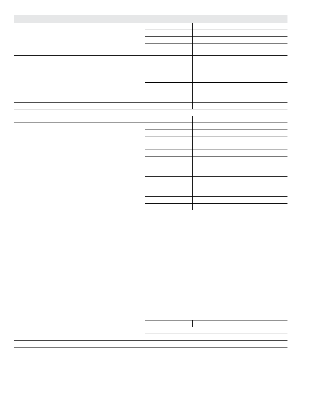
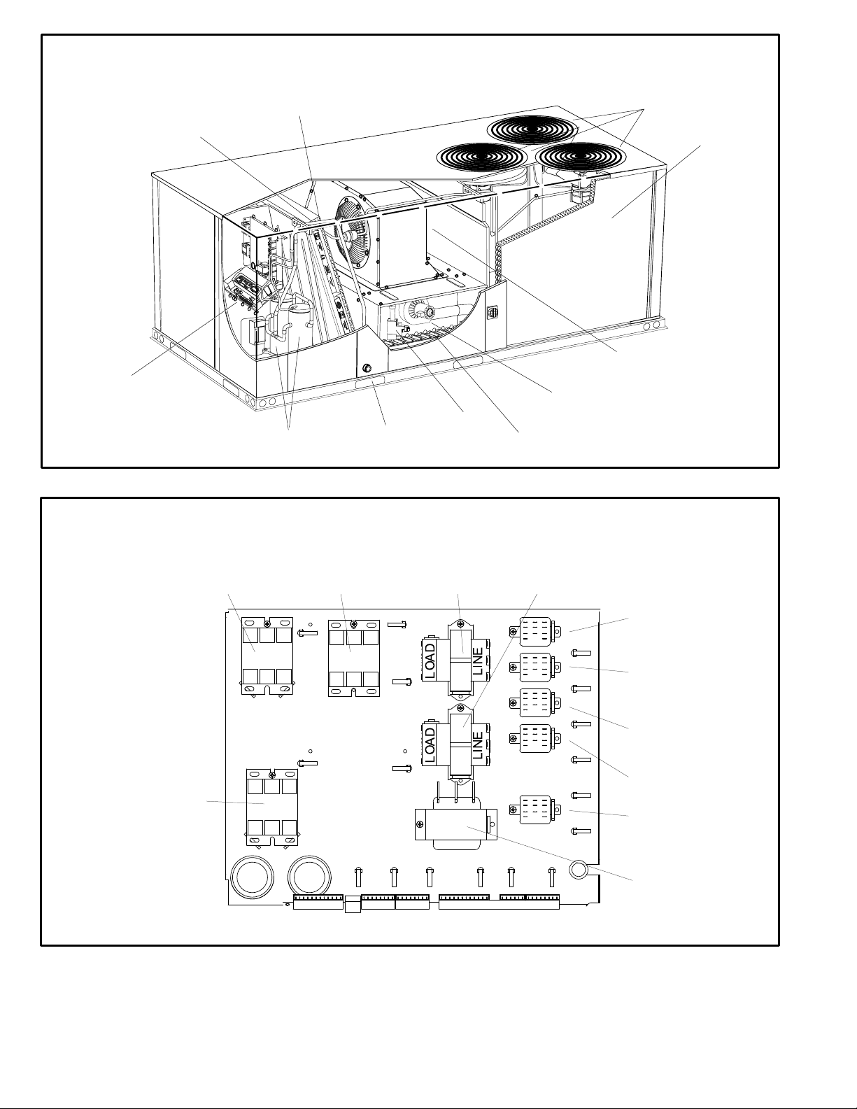
UNIT
CONTROLLER
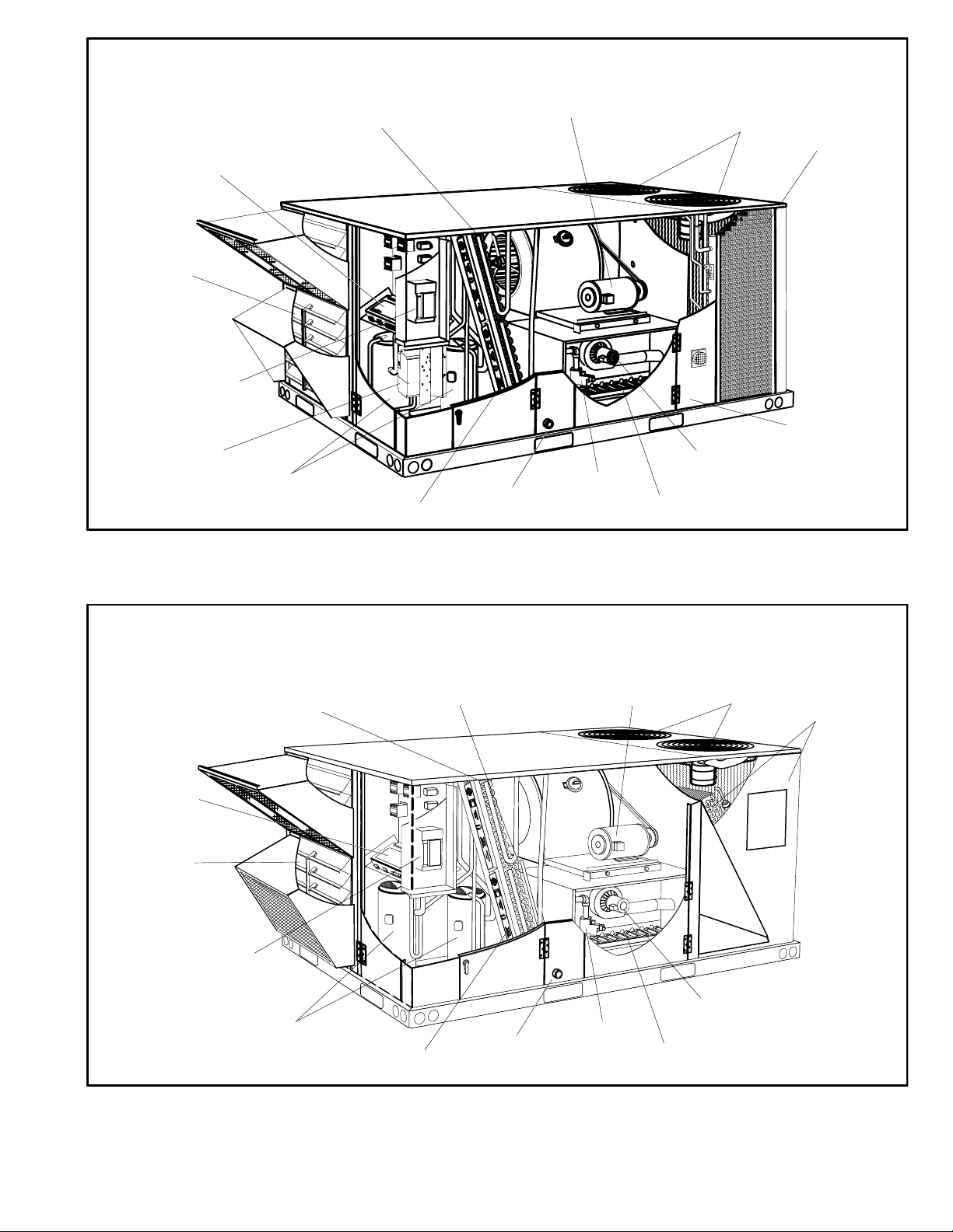
PARTS ARRANGEMENT - 092H, 102H, 120H, 150S
ALL-ALUMINUM COIL SYSTEM
EVAPORATOR
COIL
BLOWER
MOTOR
CONDENSER
FANS
CONDENSER
COIL
ECONOMIZER
(OPTIONAL)
DISCONNECT /
CIRCUIT BREAKER
(FACTORY OR FIELD
INSTALLED OPTION)
INVERTER
(OPTIONAL)
COMPRESSORS
EVAPORATOR
COIL
3
3
BLOWER
COMBUSTION
AIR INDUCER
FILTERS
(FOUR - 20 X 25 X 2”)
CONDENSATE
DRAIN
GAS VALVE
BURNERS
PARTS ARRANGEMENT - 092H, 102H, 120H, 150S
FIN/TUBE COIL
REHEAT COIL
(Hot Gas Reheat
Units Only)
BLOWER
MOTOR
CONDENSER
FANS
HINGED
ACCESS PANEL
(OPTIONAL)
CONDENSER
COILS
UNIT
CONTROLLER
ECONOMIZER
(OPTIONAL)
DISCONNECT /
CIRCUIT BREAKER
(FACTORY OR FIELD
INSTALLED OPTION)
COMPRESSORS
FILTERS
(FOUR - 20 X 25 X 2”)
33
33
LL
LL
EE
EE
NN
NN
NN
NN
OO
OO
XX
XX
CONDENSATE
DRAIN
FIGURE 2
Page 25
BLOWER
BLOWER
GAS VALVE
COMBUSTION
AIR INDUCER
BURNERS
(FOUR - 20 X 25 X 2”)
UNIT
CONTROLLER
FILTERS
PARTS ARRANGEMENT - 094U, 122U, 152U
FIN/TUBE COIL
EVAPORATOR
COIL
BLOWER
COMBUSTION
AIR INDUCER
COMPRESSORS
CONDENSATE
DRAIN
GAS VALVE
BURNERS
CONDENSER
FANS
CONDENSER
COIL
BLOWER MOTOR THIS
SIDE OF HOUSING
(DIRECT DRIVE SHOWN)
COMPRESSOR 2
CONTACTOR
K1
COMPRESSOR 1
CONTACTOR
FIGURE 3
CONTROL BOX PARTS ARRANGEMENT -
STANDARD AND HIGH EFFICIENCY NON-CE UNITS
K2
K3
BLOWER
CONTACTOR
T1
CONTROL
TRANSFORMER
T3
T43 REHEAT
TRANSFORMER
K65
EXHAUST
FAN RELAY
K10
OUTDOOR
FAN 1 RELAY
K68
OUTDOOR
FAN 2 RELAY
K13
CAB RELAY
K125
HEAT SHUT
OFF RELAY
T3
CAB
TRANSFORMER
FIGURE 4
Page 26
 Loading...