

Page 1
agency or the gas supplier.
WARNING
Improper installation, adjustment, alteration, service or
maintenance can cause property damage, personal injury
or loss of life. Installation and service must be performed
by a licensed professional installer (or equivalent), service
agency or the gas supplier.
CAUTION
As with any mechanical equipment, personal injury can
result from contact with sharp sheet metal edges. Be
careful when you handle this equipment.
Table Of Contents
LF25-030/105 Compact Unit Dimensions.......................2
Compact Unit Parts Arrangement ...................................3
LF25-125/200 Standard Unit Dimensions ......................4
LF25-250/400 Standard Unit Dimensions ......................5
Standard Unit Parts Arrangement...................................6
Shipping..........................................................................7
Optional Accessory ......................................................... 7
Requirements in USA .....................................................7
Requirements in Canada ................................................ 7
Additional Requirements ................................................8
Unit Heater Installation ...................................................8
Combustion and Ventilation Air.......................................8
Rotation of Combustion Air Inducer - 125/150................9
Venting............................................................................9
Electrical Connections .................................................. 14
INSTALLATION
INSTRUCTIONS
LF25
30,000 to 400,000 Btuh Series
UNIT HEATERS
507930-01
8/2019
Supersedes 3/2019
Gas Connection ........................................................... 18
Leak Check ..................................................................18
Unit Start-Up ................................................................ 18
To Turn O Gas to Unit ................................................ 19
Heating Sequence of Operations ................................19
Ignition Control LED ....................................................20
High Altitude Adjustments ............................................ 20
Gas Flow .....................................................................20
Gas Pressure Adjustments .......................................... 20
Limit Control Switch ...................................................... 21
Louver Vane Adjustment .............................................. 21
Combustion Air Pressure Switch .................................21
Flame Rollout Switch ................................................... 21
Service..........................................................................21
Start-Up and Performance Checklist ........................... 22
Failure to
ly could result in serious injury, death,
or property damage.
Be sure to read and understand the
structions in this manual.
ation, service or maintenance can cause
serious injury, death or property damage.
Do not store or use gasoline or other
cinity of this or any other appliance.
formed by a qualified installer, service
RETAIN THESE INSTRUCTIONS
FOR FUTURE REFERENCE
WARNING
FIRE OR EXPLOSION HAZARD.
WHAT TO DO IF YOU SMELL GAS:
Do not try to light any appliance.
Do not touch any electrical switch; do not use
any phone in your building.
Leave the building immediately.
Immediately call your gas supplier from a
neighbor's
structions.
If you cannot reach your gas supplier, call the
fire department.
Page 1
Page 2
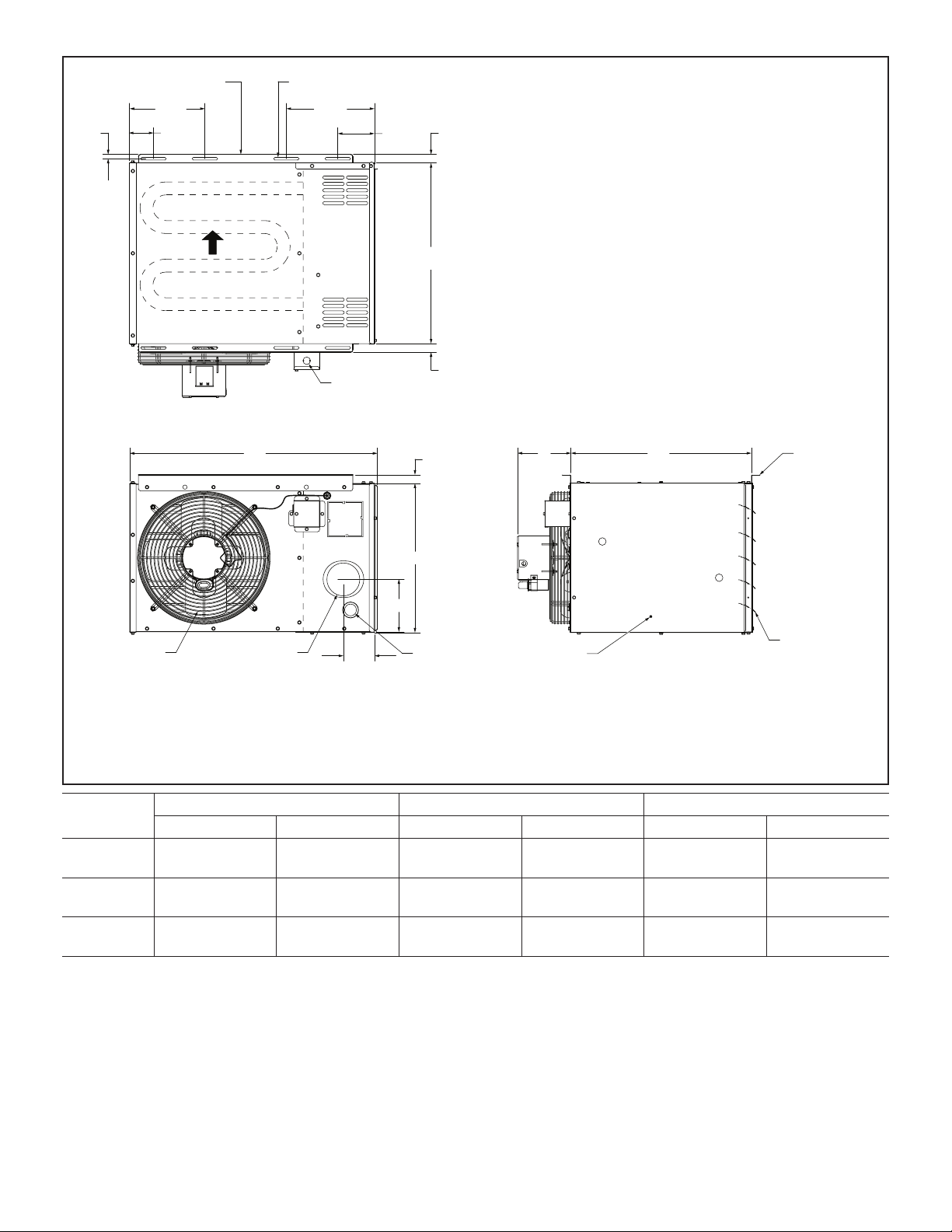
1/2
[13]
HANGING
BRACKETS (2)
8-3/4
(222)
2-3/4
(70)
AIR
FLOW
HEAT EXCHANGER
TOP VIEW
MOUNTING SLOTS (Typical)
5/16 x 3 Inches (8 x 76 mm)
10-1/2
(267)
ELECTRICAL
INLET
4-1/4
(108)
21
(533)
(25)
(25)
1
1
DIRECT
DRIVE FAN
Model
No.
LF25-030A
LF25-045A
LF25-060A
LF25-075A
LF25-090A
LF25-105A
29
(737)
FLUE
OUTLET
BACK VIEW
3-5/8
(92)
1
(25)
A
C
GAS
INLET
B 21
SERVICE
ACCESS
PANEL
(533)
SIDE VIEW
HANGING
BRACKETS (2)
ADJUSTABLE
LOUVERS
A B C
in. mm in. mm in. mm
12-3/8 314 6-1/2 165 3-7/8 98
17-1/2 445 6-1/4 159 6-1/8 156
23 584 7-7/8 200 9-1/8 232
Page 2
Page 3
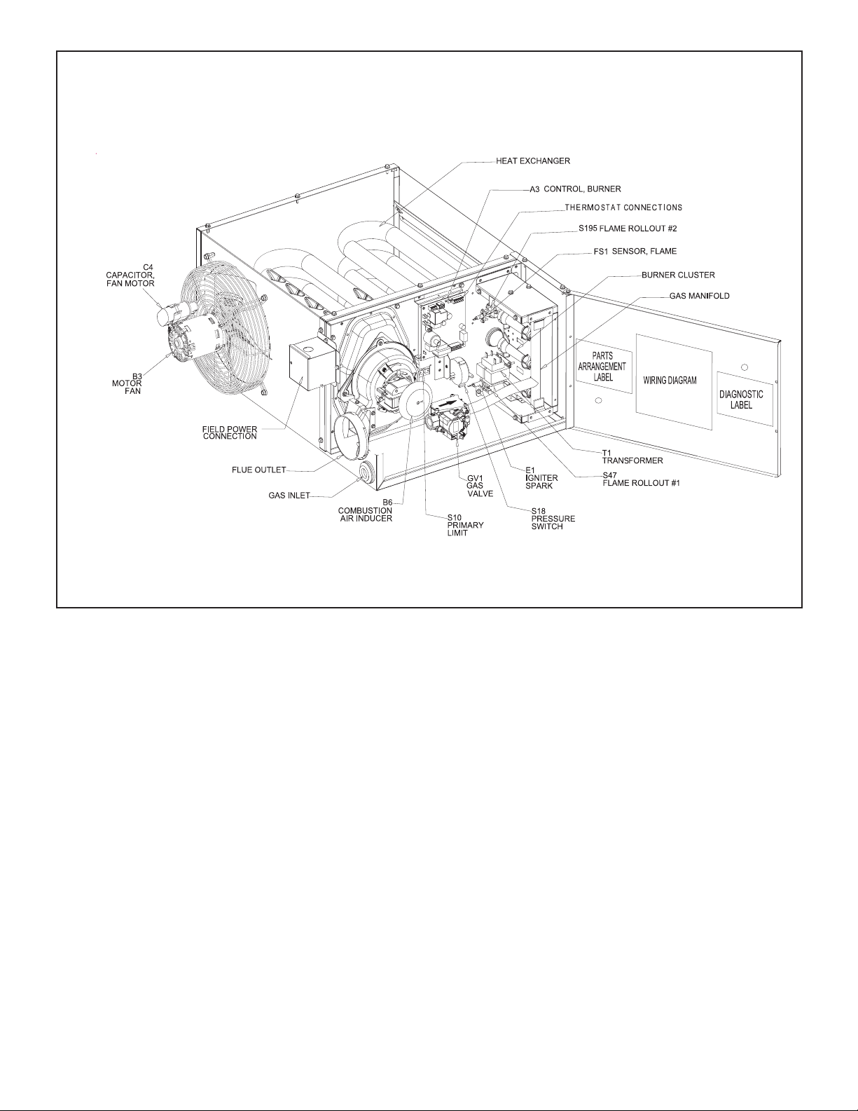
LF25 COMPACT UNIT HEATER PARTS ARRANGEMENT
030 / 105K BTUH
Page 3
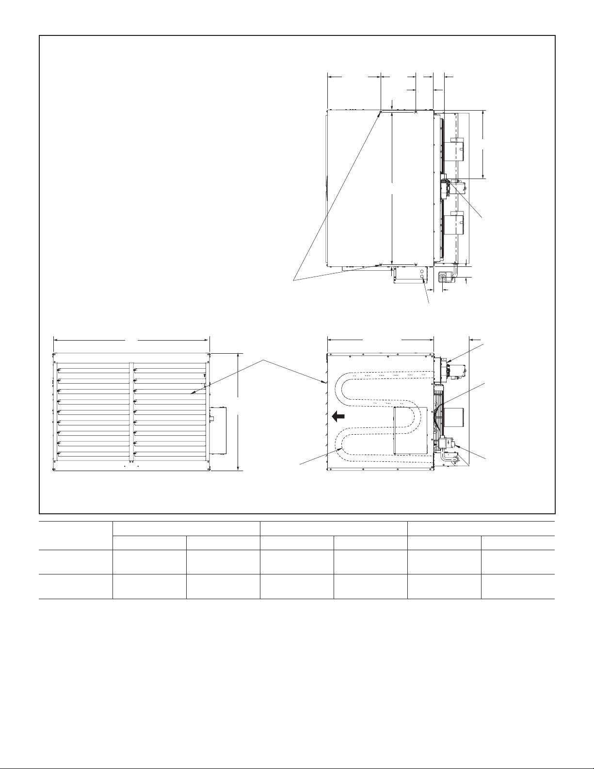
Page 4
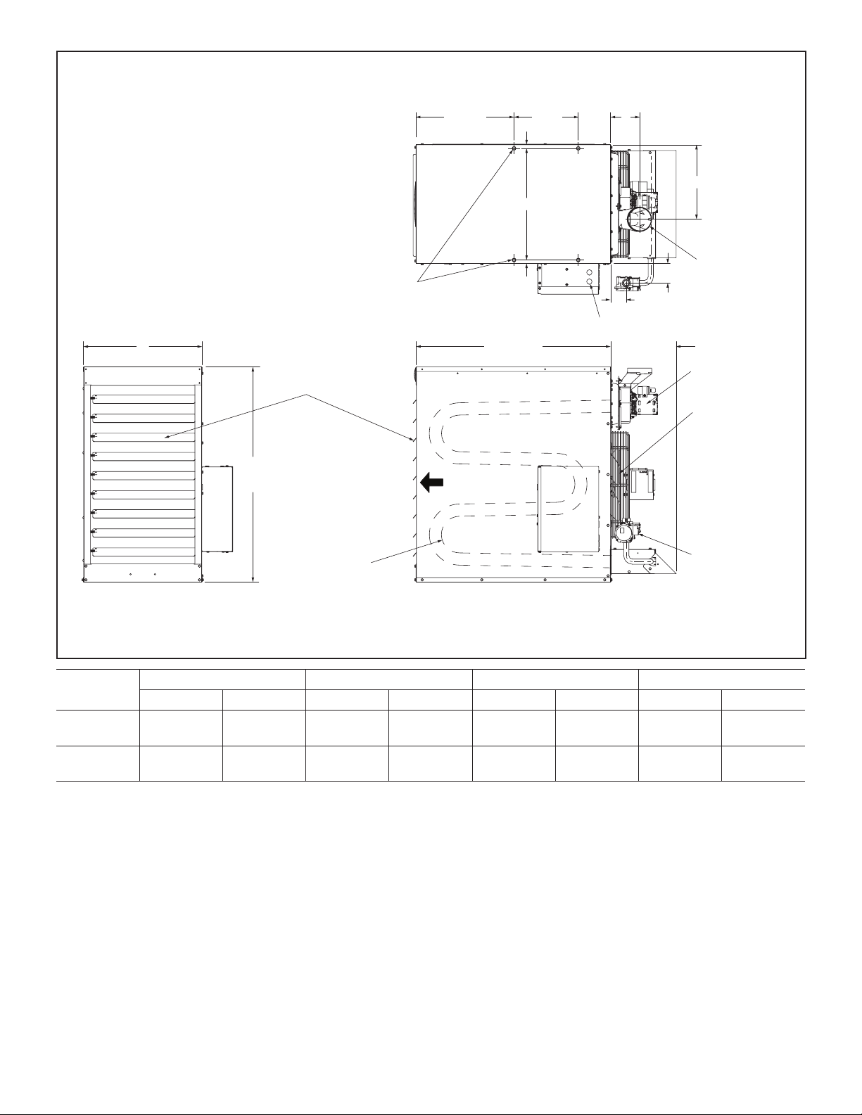
LF25-125 / 200 DIMENSIONS - Inches (mm)
16 (406)
10-1/2
1/2 (13)
B
(267)
5-3/8
(137)
D
C
A
FRONT VIEW
35-1/4
(895)
ADJUSTABLE
LOUVERS
(4) 3/8-16 MOUNTING NUTS
FOR UNIT SUSPENSION
HEAT
EXCHANGER
AIR
FLOW
1/2 (13)
TOP VIEW
31-7/8 (810)
SIDE VIEW
3-1/8 (79)
2-1/2 (64)
ELECTRICAL INLETS
10-5/8
(270)
FLUE OUTLET
COMBUSTION AIR
INDUCER
DIRECT DRIVE FAN
GAS VALVE
Model
No.
LF25-125
LF25-150
LF25-175
LF25-200
A B C D
in. mm in. mm in. mm in. mm
19-1/2 495 18-1/2 470 12-1/4 311 4-3/4 121
25 635 23-3/4 603 9-1/2 241 3 76
Page 4
Page 5
LF25-250 / 400 DIMENSIONS - Inches (mm)
16 (406)
10-1/2
(267)
1/2 (13)
B
5-3/8
(137)
(76)
3
C
FLUE OUTLET
Model
No.
LF25-250
LF25-300
LF25-350
LF25-400
A
FRONT VIEW
in. mm in. mm in. mm
37-5/8 956 36-1/2 927 15-7/8 403
47 1194 45-3/4 1162 20-1/2 521
(4) 3/8-16 MOUNTING NUTS
FOR UNIT SUSPENSION
1/2 (13)
3-1/8 (79)
2-5/8 (67)
ELECTRICAL INLETS
TOP VIEW
10-5/8
(270)
35-1/4
(895)
ADJUSTABLE
LOUVERS
EXCHANGER
31-7/8 (810)
AIR
FLOW
HEAT
SIDE VIEW
A B C
COMBUSTION AIR
INDUCER
DIRECT DRIVE FAN
GAS VALVE
Page 5
Page 6
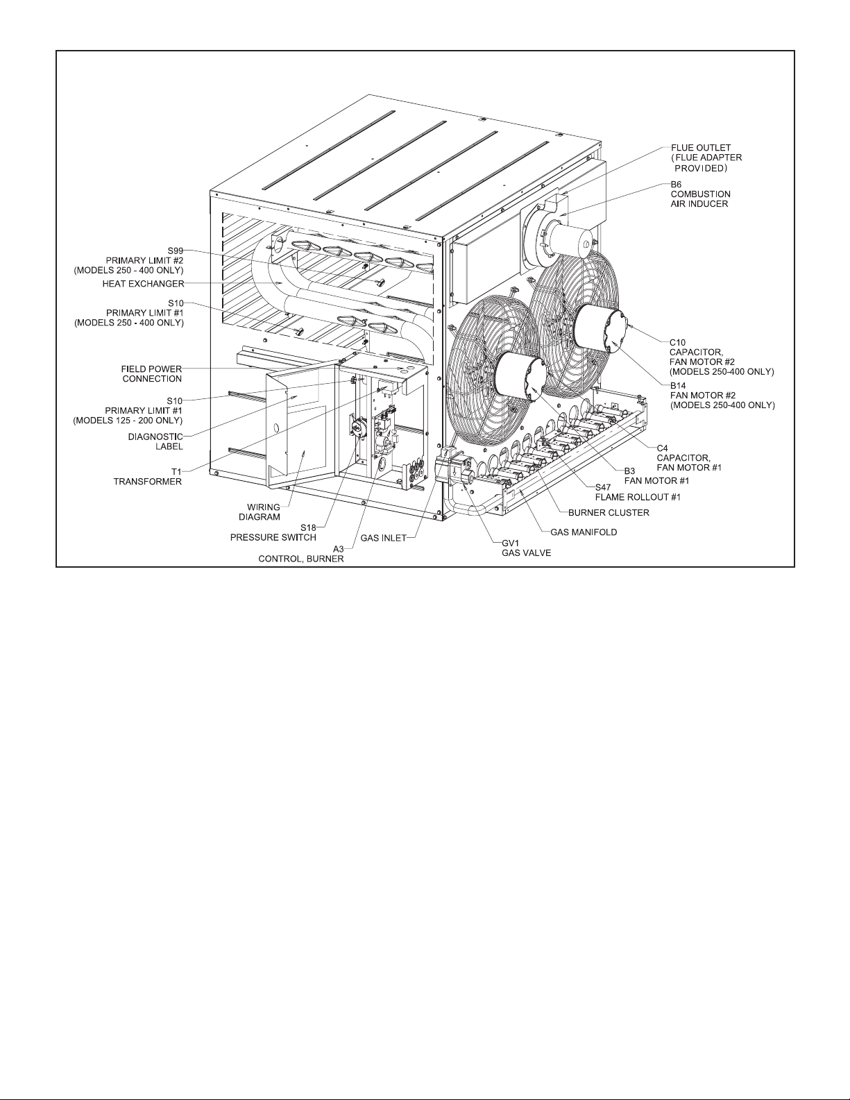
LF25 STANDARD UNIT HEATER PARTS ARRANGEMENT
125 / 400K BTUH
Page 6
Page 7
Shipping
Shipping contents includes heater, installation instructions, warranty certificate, 3D brand badge, two
mounting brackets (shipped loose in LF25-30/105
units), and a flue transition (included in LF25175/400 units only). The heater is shipped completely assembled. Check the unit for shipping damage.
The receiving party should contact the last carrier
immediately if any shipping damage is found.
Optional Accessory
Units require a changeover kit when the unit is to be used
with LP/propane gas. The kit is ordered separately. See
Engineering Handbook.
Requirements in USA
Installation of gas unit heaters must conform with local
building codes or, in the absence of local codes, with the
current edition of ANSI Z223.1, National Fuel Gas Code.
Installation in aircraft hangers must be in accordance with
the current edition of ANSI/NFPA No. 409, Standard for
Aircraft Hangers.
Installation in parking structures must be in accordance
with the current edition of ANSI/NFPA No. 88A, Standard
for Parking Structures.
Installation in repair garages must be in accordance with
the current edition of ANSI/NFPA No. 88B, Standard for
Repair Garages.
These units are approved for residential garage or
non-conned living space applications. For installation
in a residential garage or non-conned living space, unit
must be installed so that burners and ignition source are
located no less than 18” (457mm) above oor. Heater
must be located or protected to avoid physical damage
by vehicles. Refer to the current edition of ANSI Z223.1,
National Fuel Gas Code.
Authorities having jurisdiction should be consulted before
installation. Air for combustion and ventilation must con-
form to the methods outlined in the current edition of ANSI
Z223.1, Section 5.3, Air for Combustion and Ventilation, or
applicable provisions of local building codes.
The National Fuel Gas Code (ANSI Z223.1) is available
from:
American National Standard Institute Inc.
11 West 42nd Street
New York, NY 10036
These unit heaters are CSA International design-certied.
These unit heaters are certied for installation to combus-
tible material as listed in Table 1 and on unit rating plate.
Accessibility and service clearances must be observed in
addition to re protection clearances.
All electrical wiring and grounding for unit must be in accordance with the regulations of the current edition of
ANSI/NFPA No. 70, National Electric Code.
The National Electric Code is available from:
National Fire Protection Association
1 Batterymarch Park
PO Box 9101
Quincy, MA 02269-9101
Page 7
Requirements in Canada
These instructions are intended only as a general guide
and do not supersede local codes in any way. Authorities
having jurisdiction should be consulted before installation.
The installation must conform with local building codes or,
in the absence of local codes, with the current edition of
CSA-B149 installation compliance codes. All electrical wiring and grounding for the unit must also comply with the
current edition of CSA C22.1, Canadian Electrical Code.
These unit heaters are CSA-certied for the installation
clearances listed on the rating plate and in table 1.
Adequate clearance must be provided around the appli-
ance and around air openings into the combustion chamber. Provision shall be made for service accessibility.
NOTE - Fire protection clearances may be exceeded to
provide additional space for service and accessibility.
GARAGE / WAREHOUSE INSTALLATIONS
1 - In a storage area, clearance from heaters to
combustible materials must be such that the
combustible material must not attain a temperature
above 160°F (71°C) by continuous operation of the
unit.
WARNING
Combustible materials that are aected by exposure to
temperatures LESS than 160°F (plastics, plastic wrap,
styrofoam, cardboard, etc.) must be stored well away
from this heater. Discharge air temperatures for these
units can approach 200°F.
2 - Maintain an 8-foot (2m) minimum clearance from the
oor to the bottom of the heater. Refer to the current
edition of CSA-B149 for installation compliance
codes.
AIRCRAFT HANGER
1 - In an area where aircraft are housed or serviced, a
10-foot (3m) minimum clearance from the highest
surface of the aircraft to bottom of the heater must
be maintained.
2 - In other areas, an 8-foot (2m) minimum clearance
from the oor to bottom of heater must be maintained.
3 - Heaters should be located so that they are protected
from damage from aircraft or other appliances needed
for servicing of aircraft. Refer to requirements of the
enforcing authorities.
RESIDENTIAL
These units are approved for residential garage or
non-conned living space applications. For installation
in a residential garage or non-conned living space, unit
must be installed so that burners and ignition source are
located no less than 18” (457mm) above oor. Heater
must be located or protected to avoid physical damage by
vehicles. Refer to the current edition of CSA-B149 for installation compliance codes. In a conned area, the heater must be installed in accordance with the current edition
of CSA-B149 installation compliance codes. Be sure to
check with local codes and ordinances for additional requirements.
Page 8

TABLE 1
UNIT CLEARANCES TO COMBUSTIBLE MATERIALS
Unit
030/105 1 25 1 25 1 25 18 457 6* 152
125/400 6 152 18 457 1 25 18 457 6 152
Top Side** Bottom Back Flue
in mm in mm in mm in mm in mm
*6” is for single wall. Double wall B-vent clearance will be
in accordance with the manufacturer’s listing.
**Access panel or control box side of unit should have 24”
(610mm) clearance.
Additional Requirements
The Commonwealth of Massachusetts stipulates the following additional requirements:
1 - Gas furnaces shall be installed by a licensed
plumber or gas tter only.
2 - The gas cock must be “T handle” type.
Unit Heater Installation
The appliance shall not be installed downstream from
evaporator coils or cooling units.
Install the unit in the desired location as governed by
clearances, vent connection, air direction, gas supply,
electrical supply and service accessibility.
Unit is shipped ready for installation.
CAUTION
Do not install unit heaters in close proximity to re
sprinklers. Unit heater normal operating temperatures
could result in re sprinkler activation.
LF25-30/105
Unit may be installed as shown in gure 1 or rotated
180°.
1 - Push each louver to the right to depress spring and
release locking tab on the other end (locking tab
keeps the louver in place for shipping).
2 - If installing unit in a rotated position - release locking
tabs in the same manner as previous step. Rotate
each louver 180° and reinstall. Remove and retain
screws securing access panel. Rotate access panel
180° and resecure using retained screws.
3 - Rotate louvers to direct airow as desired.
4 - Choose location for mounting brackets.
5 - Align mounting brackets with pilot holes on the top or
bottom (when rotating) edge of the unit. Secure with
screws provided in bag assembly.
6 - To support unit, secure mounting bracket to ceiling
joist or truss. Unit may also be supported using
support rods as shown in gure 1.
7 - Install the 3D brand badge provided with the unit.
INSTALL UNIT HEATER
(030 / 105 SHOWN)
MOUNTING
BRACKETS
(2)
SUPPORT
RODS
LF25-125/400 UNITS
Four mounting nuts are furnished. Refer to dimension
illustration. Mounting nuts will accommodate 3/8” x 16
threaded rods.
1 - Push each louver to the left to depress spring and
release locking tab on the other end (locking tab
keeps the louver in place for shipping).
2 - Rotate louvers to direct airow as desired.
3- Cut threaded rods to desired length and slide a 3/8”
nut onto the rod.
4 - Slide a at washer onto the threaded rod AFTER the
nut (7/16” inside diameter X 1” outside diameter X
1/16” thick washer).
5 - Screw the rods (two or four) into the mounting nuts
on the unit.
6 - Tighten nuts to secure unit to rods.
7 - Install the 3D brand badge provided with the unit.
TABLE 2
MAXIMUM MOUNTING HEIGHTS - 125/400
Unit Feet (Meters)
LF25-125/150 16 (4.9)
LF25-175/200 20 (6.1)
LF25-250/400 30 (9.1)
ACCESS PANEL
FIGURE 1
Combustion and Ventilation Air
Adequate facilities for supplying air for combustion and
ventilation must be provided in accordance with the current edition of ANSI Z223.1, section 5.3 and CSA-B149
installation compliance codes, or applicable provisions of
local building codes.
All gas-red appliances require air to be used for combustion. In many buildings today, there is a negative in-
door air pressure caused by exhaust fans, etc. If sucient
quantities of combustion air are not available, the heater
Page 8
Page 9

or another appliance will operate in an inecient manner,
resulting in incomplete combustion which can result in the
production of excessive carbon monoxide.
WARNING
Insucient combustion air can cause headaches,
nausea, dizziness or asphyxiation. It will also cause
excess water in the heat exchanger resulting in rusting
and premature heat exchanger failure. Excessive
exposure to contaminated combustion air will result
in safety and performance related problems. Avoid
exposure to the following substances in the combustion
air supply:
Permanent wave solutions
Chlorinated waxes and cleaners
Chlorine base swimming pool chemicals
Water softening chemicals
De-icing salts or chemicals
Carbon tetrachloride
Halogen type refrigerants
Cleaning solvents (such as perchloroethylene)
Printing inks, paint removers, varnishes, etc.
Hydrochloric acid
Cements and glues
Antistatic fabric softeners for clothes dryers
Masonry acid washing materials
If indoor air is to be used for combustion, it must be
free of the following substances or the life of the heat
exchanger will be adversely aected: chlorine, carbon tetrachloride, cleaning solvent, halogen refriger-
ants, acids, cements and glues, printing inks, uorides,
paint removers, varnishes, or any other corrosives.
Rotation of Combustion Air Inducer (LF25-125 & 150 Only)
The combustion air inducer on LF25-125 & 150 may be
rotated 90° either to the left or right of the original vertical
position in order to better suit the application.
NOTE - It is not permissible to rotate the combustion air
inducer on LF25-030/105 and -175/400.
Rotate the combustion air inducer assembly as follows:
1 - Remove the heater from the carton. Decide the best
unit heater orientation. The vent can be installed in
one of three discharge positions: up, left, or right.
2 - If the inducer is to be rotated, follow the instructions
in this section; otherwise, refer to instructions under
“Venting” section.
3 - Before making an electrical or gas connections, use
a socket to remove the four screws which secure the
combustion air inducer to the ue box. See gure 2.
4 - Rotate the inducer 90° to the desired position.
Reinsert and tighten the inducer securing screws.
5 - The unit heater is now ready for installation as
described in the Venting section.
FLUE BOX AND COMBUSTION AIR
INDUCER ASSEMBLY
125/150
VEST PANEL
FLUE BOX
GASKET
FLUE BOX
ORIFICE
PLATE
ORIFICE
PLATE GASKET
COMBUSTION
AIR INDUCER
FIGURE 2
Venting
NOTE - The vent is a passageway, vertical or nearly so,
used to convey ue gases from an appliance, or its vent
connector, to the outside atmosphere. The vent connector
is the pipe or duct that connects a fuel-gas-burning appliance to a vent or chimney.
NOTE - Local codes may supersede any of these provisions.
GENERAL RECOMMENDATIONS AND
REQUIREMENTS
Unit heaters must be vented in compliance with the latest edition of the National Fuel Gas Code (NFPA 54 /
ANSI Z223.1) in the USA and with CSA-B149.1 codes in
Canada, as well as applicable provisions of local building
codes, and the following instructions.
030-150 Units - The transition is a part of the combustion air blower.
175-400 Units - A stamped/extruded metal transition
is supplied with this certied unit. It must not be modied or altered and must be installed on the outlet
of the combustion air inducer assembly prior to the
installation of the vent connector. Failure to comply
with this requirement will void the certication of the
unit by the approval agencies.
A single-wall vent connector may be used between the
furnace and the vertical vent pipe in all applications; however, single-wall vent material cannot be used for
vertical vent piping in residential applications. UL-approved Category III venting materials must be used
in all residential applications which vent horizontally.
Page 9
Page 10

A single-wall vent pipe used as a vent connector in residential or commercial applications, or as a vertical vent in
commercial applications, must have all seams and joints
sealed with pressure-sensitive aluminum tape or silicone
rubber sealant. Aluminum tape must meet the provisions
of SMACNA AFTS-100-73 Standards. The aluminum tape
must have a temperature rating of 400°F (204°C). Silicone
rubber sealant must have a temperature rating of 482°F
(250°C), i.e., Dow Corning RTV-736 or equivalent. All
joints must be secured with at least two corrosion-resistant
screws. All joints must be checked for gas tightness after
installation. Single-wall vent pipe used as vertical vent in
commercial applications must not pass through any attic,
interior wall, concealed space, or oor.
VERTICAL VENTS USING METAL VENT PIPE -
COMMERCIAL AND RESIDENTIAL INSTALLATIONS
These compact unit heaters are listed as Category 1
appliances for vertical vent installations.
1 - These unit heaters are to be used with NFPA- or
ANSI-approved chimneys or U.L.-listed type B-1
gas vents, or listed chimney lining systems for gas
venting where applicable, as well as the modications
and limitations listed in gure 3. Seal single-wall vent
material according to General Recommendations
and Requirements section.
2 - The vent connector shall be 4” (102mm) diameter on
30K, 45K, 60K, 75K, 090K, 105K, 125K, and 150K
Btuh units; 5” (127mm) diameter on 175K, 200K,
250K, & 300K Btuh units; 6” (152mm) on 350K &
400K Btuh units. On 175-400 units, a ue transition
piece (supplied) is required to t over the outlet of the
induced draft assembly on the appliance.
NOTE - If needed, loosen the upper right two or three
screws securing the combustion air blower. Slide the transition into place and secure loosened screws.
3 - Keep the vent connector runs as short as possible
with a minimum number of elbows. Refer to the
current edition of ANSI Z223.1 or CSA-B149
installation compliance codes for maximum vent and
vent connector lengths.
4 - The entire length of a single-wall metal vent connector
shall be readily accessible for inspection, cleaning
and replacement.
5 - Single-wall vent pipe used as vertical vent in
commercial applications must not pass through any
attic, interior wall, concealed space, or oor.
TABLE 3
MAXIMUM HORIZONTAL VENT CONNECTOR AND
HORIZONTAL VENT PIPE LENGTHS
No. of
Elbows
1 25 7.6 35 10.7
2 20 6.1 30 9.1
3 15 4.6 25 7.6
4 10 3.0 20 6.1
5 5 1.5 15 4.6
6 - - 10 3.0
7 - - 5 1.5
30, 45, 60, 75, 90, 105, 125,
150, 175, 200, 350, 400
ft m ft m
250 & 300
SINGLE-WALL VENT PIPE WITH
SINGLE-WALL TERMINATION
ROOF FLASHING
ROOF PITCHED
FROM 0” TO 45”
VENT TERMINATION ON SINGLE-WALL VERTICAL VENT RUNS
Commercial Application Only
SINGLE-WALL VENT PIPE WITH
DOUBLE-WALL (TYPE B-1) TERMINATION
ROOF FLASHING
ROOF PITCHED
FROM 0” TO 45”
12” MAX
2” CLEARANCE
THIMBLE
SEAL JOINT BETWEEN SINGLE-WALL VENT AND “B” VENT TERMINATION
AND THE OPEN SPACE BETWEEN THE SINGLE WALL VENT PIPE AND
THE OUTER PIPE OF THE “B” VENT TERMINATION.
FIGURE 3
CLEARANCE TO BE
AS SPECIFIED ON
TYPE “B” VENT PIPE.
Page 10
Page 11

6 - The unit may be vented vertically as a single appliance
or in a common vent with other gas-red appliances.
In common venting situations, vent connectors for
other appliances must maintain a 4” (102mm) vertical
separation between the vent connectors. Refer to
common venting tables in the current editions of
ANSI Z223.1 or CSA-B149 installation compliance
codes for proper vent size.
7 - Clearance to combustible material is 6” (152mm)
for single-wall vent material except where a listed
clearance thimble is used. Clearance to combustible
material for type B-1 vent or factory-built chimney is
per manufacturer’s instructions.
8 - The vent connector shall be supported without any
dips or sags. Vertical vents shall be supported in
accordance with their listing and manufacturers’
instructions. All horizontal vent connector runs shall
have a slope up to the vertical vent of at least 1/4”
per foot (1mm per 50mm).
9 - All vertical type B-1 vents, single-wall vertical vents
(commercial applications), or listed chimney lining
systems must be terminated with a UL-listed (or other
equivalent agency) vent cap or listed roof assembly.
10 - The vent must extend at least 3 feet (1m) above
the highest point where it passes through a roof
of a building. The vent must also extend at least 2
feet (1m) higher than any part of a building within a
horizontal distance of 10 feet (3m) unless otherwise
specied by ANSI Z223.1 or CSA-B149 installation
compliance codes. The vent must extend at least 5
feet (2m) above the highest connected equipment
ue collar
HORIZONTAL VENTING
NOTE - Common venting is not allowed when horizontally
venting the unit heater.
NOTE - Precautions must be taken to prevent degradation
of building materials by ue products.
If the LF25 unit heater is to be horizontally vented, a positive pressure may be created in the vent. The unit heater,
when installed with horizontal venting, will perform as a
category III appliance.
1 - In residential applications which vent horizontally,
use only special vent materials approved for use
with Category III appliances.
2 - The vent pipe diameter for horizontal installations
shall be 4” (102mm) diameter on 30K, 45K, 60K,
75K, 090K, 105K, 125K, and 150K Btuh units; 5”
(127mm) diameter on 175K, 200K, 250K, & 300K
Btuh units; 6” (152mm) on 350K & 400K Btuh units.
On 175-400 units, a ue transition piece (supplied)
is required to t over the outlet of the induced draft
assembly on the appliance.
3 - The minimum horizontal vent length is 5 feet (2m).
4 - Refer to table 3 for maximum horizontal vent lengths.
5 - If possible, do not terminate the horizontal vent through
a wall that is exposed to prevailing wind. Exposure
to excessive winds can aect unit performance. If
such a termination is necessary, use a wind block to
protect the vent termination from direct winds.
6 - Horizontal vent termination must be free from
obstructions and at least 12” (305mm) above grade
level and maximum snow height.
7 - Do not install a horizontal vent termination directly
below roof eaves or above a public walkway, or
any other area where condensate dripping may be
troublesome and may cause some staining. Avoid
windows where steam may cause fogging or ice
buildup.
8 - Minimum clearance for horizontal vent termination
from any door, window, non-mechanical air supply
inlet is 4 feet below or to the side of opening; 1
foot above opening horizontally for United States
installations. In Canada, minimum clearance for
horizontal vent termination from any door, window,
non-mechanical air supply inlet or the combustion
air inlet to any other appliance is 12 inches for
appliances >10,000 to 100,000 Btuh, and 36 inches
for appliance >100,000 Btuh.
9- Vent terminal clearance to each side of a centerline
extended above a meter/regulator assembly and
service regulator vent outlet must be in accordance
with local installation codes and the requirements of
the gas supplier for installations in the United States.
In Canada the clearance to each side of a centerline
extended above meter/regulator assembly and
service regulator vent outlet must be 3 feet(1m) within
a height 15 feet above the meter/regulator assembly
and 3 feet to a service regulator vent.
Refer to latest editions of the ANSI Z223.1 or CSA-B149
for installation compliance codes and with local authorities with jurisdiction.
10 - Vent termination clearance to an unvented sot or
within 2 feet horizontally of a ventilated sot must
be in accordance with local installation codes and
the requirements of the gas supplier.
11 - When a vent termination is inside a corner formed
by two exterior walls the clearance must be in
accordance with local installation codes and the
requirements of the gas supplier.
12 - Vent termination must be a minimum of 3 feet(1m)
above any forced air inlet (includes fresh air inlet
for other appliance, such as a dryer) if within 10
feet horizontally for United States installations. In
Canada, vent termination must have 6 feet (2m)
minimum clearance to a mechanical air-supply inlet
of any building.
13 - When termination is routed through combustible
wall, vent termination must be supported using a
restop to maintain clearances specied on unit
rating plate. Inside edge of vent termination must
be at least 16” (406mm) from outside wall
14 - All horizontal vents which use special vent pipe for
use with Category III appliances must terminate
with an approved Category III tee. Opening end
must face downward.
15 - For horizontal venting, the vent pipe shall be
supported with hangers no more than 3 feet (1m)
apart to prevent movement after installation.
Page 11
Page 12

CONDENSATE DRAIN THROUGH TEE PIPE AND DRAIN LOOP
FLUE TRANSITION
(PROVIDED)
12” (30.5CM)
MINIMUM ABOVE
HIGHEST SNOWFALL
16 INCHES MIN.
(41 CM )
GROUND LEVEL
UPWARD SLOPE ON HORIZONTAL VENT -- RESIDENTIAL OR COMMERCIAL APPLICATION
COMMON VENTING NOT ALLOWED WHEN HORIZONTALLY VENTING THE UNIT HEATER.
COMBUSTION
AIR INDUCER
Category III adaptor
must be installed
before optional elbow
(if used).
LISTED WALL
THIMBLE
THROUGH
COMBUSTIBLE
WALL
NOTE - Minimum horizontal vent length is 5 ft.
This does not include termination tee. Refer to
table 3 for maximum length and number of elbows.
VENT
TERMINATION
TEE
DRAIN
TEE
DRAIN LOOP (PROVIDED BY
INSTALLER WITH WATER TRAP
TO CONDENSATE DRAIN
RESIDENTIAL APPLICATIONS -Venting must be listed special
vent for Category III appliances.
COMMERCIAL APPLICATIONS
-- Venting may be single-wall (26
GSG) galvanized or equivalent
stainless steel vent pipe sealed
per these instructions, OR listed
special vent for Category III
appliances.
SLOPE = 1/4 IN. PER FOOT
RUN MAXIMUM.
16 - Select a wall termination point that will maintain 1/4”
(6mm) rise per foot (305mm) slope of horizontal run
of vent pipe.
17 - For upward sloped vent, a condensate tee and
drain must be installed within the rst 5 feet (2m)
from the unit heater to protect the appliance. If a
exible condensate drain line is used, the drain
line must include a loop lled with water to prevent
combustion products from entering the structure. If
the unit is shut down for an extended period of time
and will be exposed to sub-freezing temperatures,
the condensate may freeze.
18 - Select a wall termination point that will maintain 1/4”
rise per foot slope of horizontal run of vent pipe. In
areas where authorities having jurisdiction permit,
a downward slope of maximum 1/4” per foot is also
acceptable. Condensate drainage can be collected
in a tee pipe section (gure 4) with drain loop similar
to one used for upward slope vent, or allowed to
drip through the vent termination, if permitted by
authorities (gure 6).
NOTE − Minimum
horizontal vent length is
DOWNWARD SLOPE ON HORIZONTAL VENT − RESIDENTIAL OR COMMERCIAL APPLICATION
CONDENSATE DRAIN THROUGH TEE PIPE AND DRAIN LOOP
5 ft. This does not
include termination tee.
Refer to table 3 for
maximum length and
number of elbows.
COMMON VENTING
NOT ALLOWED WHEN
HORIZONTALLY
VENTING THE
UNIT HEATER.
RESIDENTIAL APPLICATIONS −− Venting must be
listed special vent for Category III appliances.
COMMERCIAL APPLICATIONS −− Venting may be
single−wall (26 GSG) galvanized or equivalent
stainless steel vent pipe sealed per these instructions,
OR listed special vent for Category III appliances.
SLOPE = 1/4 IN. PER FOOT RUN MAXIMUM.
Category III
adaptor must
be installed
DRAIN LOOP WITH WATER
TRAP TO CONDENSATE
(Provided by installer)
FIGURE 4
before
optional
elbow
(if used).
DRAIN
FIGURE 5
Page 12
−
DRAIN TEE
LISTED THIMBLE
THROUGH
COMBUSTIBLE
WALL
VENT
16 INCHES
MIN. (41 CM)
TERMINATION
TEE
Page 13

CONDENSATE DRAIN THROUGH VENT TERMINATION
NOTE − Minimum
horizontal vent length is
5 ft. This does not
include termination tee.
Refer to table 3 for
maximum length and
number of elbows.
COMMON VENTING
NOT ALLOWED WHEN
HORIZONTALLY
VENTING THE UNIT
HEATER.
RESIDENTIAL APPLICATIONS −− Venting must be listed special vent
for Category III appliances.
COMMERCIAL APPLICATIONS −− Venting may be single−wall (26
GSG) galvanized or equivalent stainless steel vent pipe sealed per
these instructions, OR listed special vent for Category III appliances.
SLOPE = 1/4 IN. PER FOOT RUN MAXIMUM.
DOWNWARD SLOPE ON HORIZONTAL VENT−RESIDENTIAL OR COMMERCIAL APPLICATION
DOUBLE
MALE
ELBOW
OPTIONAL
ADAPTER
(Cat. III
kits only)
FIGURE 6
TABLE 4
Category III Horizontal Venting Components²
(Required for Horizontal Vent Applications)
LF25 Unit
30, 40, 45, 60, 75,
90, 105, 125, 150
175, 200,
250, 300
Vent
Diameter (in.)
4
5
350, 400 6
¹Length does not include termination (or elbow where applicable).
NOTE - Elbow is required where shown to facilitate connection of horizontal vent kit to ue outlet.
Upslope Vent
Kit / Cat. No.
C5VENT4KU /
75W63
C5VENT5KU /
75W64
C5VENT6KU /
75W65
Downslope Vent
Kit / Cat. No.
C5VENT4KD /
75W67
C5VENT5KD /
75W68
C5VENT6KD /
75W69
45° Elbow Kit /
Cat. No. (optional)
C5VENT4E45 /
87W80
C5VENT5E45 /
87W81
C5VENT5645 /
87W82
²Refer to EHB for vent pipe part numbers.
VENTING USING A MASONRY CHIMNEY
The following additional requirements apply when a lined
masonry chimney is being used to vent the compact unit
heater.
IMPORTANT
Single appliance venting of a fan-assisted unit heater
into a tile lined masonry chimney (interior or outside wall)
is prohibited. The chimney must rst be lined with either
type “B-1“ vent or an insulated single-wall exible vent
lining system, sized in accordance with venting tables in
the ANSI Z223.1, or CSA-B149 installation compliance
codes.
1 - Masonry chimneys used to vent Category I units
heaters must be either tile-lined or lined with a listed
metal lining system or dedicated gas vent. Unlined
masonry chimneys are prohibited. A category I
appliance must never be connected to a chimney
that is servicing a solid fuel appliance. If a replace
chimney ue is used to vent this appliance, the
replace opening must be permanently sealed.
2 - A fan-assisted unit heater may be commonly vented
into an existing lined masonry chimney provided:
a. The chimney is currently serving at least one draft-hood
equipped appliance.
b. The vent connector and chimney are sized in accordance
with venting tables.
3 - A “B1” double-wall vent or masonry chimney liner
shall terminate above the roof surface with a listed
cap or a listed roof assembly in accordance with
the terms of their respective listings and the vent
manufacturer’s instructions.
4 - Do not install a manual damper, barometric draft
regulator, or ue restrictor between the unit heater
and the chimney.
5 - If type “B1” double-wall vent is used inside a chimney,
no other appliance can be vented into the chimney.
Outer wall of type “B” vent pipe must not be exposed
to ue products.
6 - Insulation for the exible vent pipe must be an
encapsulated berglass sleeve recommended by
the exible vent pipe manufacturer.
7 - The space between liner and chimney wall should
NOT be insulated with pued mica or any other loose
granular insulating material.
LISTED THIMBLE
THROUGH
COMBUSTIBLE
WALL
16 INCHES
MIN. (41 CM)
90° Elbow Kit /
Cat. No. (optional)
C5VENT4E /
75W71
C5VENT5E /
75W72
C5VENT6E /
75W73
VENT
TERMINATION
TEE
¹Min. Vent Length
(ft.)
5
Page 13
Page 14

8 - If B-1 vent or an insulated exible vent pipe cannot
POWER WIRING.
be used as liners, the chimney must be rebuilt
to accommodate one of these methods or some
alternate approved method must be found to vent the
appliance. When inspection reveals that an existing
chimney is not safe for the intended purpose, it
shall be rebuilt to conform to nationally recognized
standards, lined or relined with suitable materials
or replaced with a gas vent or chimney suitable for
venting unit heaters. The chimney passageway must
be checked periodically to ensure that it is clear and
free of obstructions.
REMOVAL OF UNIT FROM COMMON VENT
In the event that an existing unit heater is removed from a
venting system commonly run with separate gas appliances, the venting system is likely to be too large to properly
vent the remaining attached appliances. The following test
should be conducted while each appliance is in operation
and the other appliances are not in operation, yet remain
connected to the common venting system. If the venting
system has been installed improperly, the system must be
corrected.
1 - Seal any unused openings in the common venting
system.
2 - Visually inspect the venting system for proper size and
horizontal pitch. Determine there is no blockage or
restriction, leakage, corrosion, or other deciencies
which could cause an unsafe condition.
3 - In so far as is practical, close all building doors and
windows and all doors between the space in which
the appliances remaining connected to the common
venting system are located and other spaces of the
building. Turn on clothes dryers and any appliances
not connected to the common venting system. Turn
on any exhaust fans, such as range hoods and
bathroom exhausts, so they will operate at maximum
speed. Do not operate a summer exhaust fan. Close
replace dampers.
4 - Follow the lighting instructions. Place the appliance
being inspected in operation. Adjust thermostat so
appliance will operate continuously.
5 - Test for spillage at the draft hood relief opening after
ve minutes of main burner operation. Use the ame
of a match or candle, or smoke from a cigarette,
cigar, or pipe.
6 - After it has been determined that each appliance
remaining connected to the common venting system
properly vents when tested as outlined above, return
doors, windows, exhaust fans, replace dampers
and any other gas-burning appliance to their previous
condition of use.
7 - If improper venting is observed during any of the above
tests, the common venting system must be corrected.
The common venting system should be resized to approach the minimum size as determined by using the
appropriate tables in Appendix G in the current editions
of the ANSI Z223-1, or the appropriate Category I Natural Gas and Propane appliances venting sizing tables
in the current standards of the CSA-B149 for installation compliance codes.
Electrical Connections
NOTE - Local codes may supersede any of the provisions
outlined in this instruction.
The LF25 series unit heaters use a direct spark ignition
system. There is no pilot necessary as the spark lights
the main burner as the gas valve is turned on. The direct spark ignition control board emits radio noise as the
sparking process is under way. The level of energy may
be sucient to disturb a logic circuit in a microprocessor
controlled thermostat. It is recommended that an isolation relay be used when connecting the unit heaters to a
microprocessor controlled thermostat. Install the thermostat according to instructions provided. Install a separate
fused disconnect switch, with the fuse sized according to
blower motor size. Connect wiring through knockout on
the junction box located on the side of the unit heater. Refer to dimensions in the front of this instruction for location.
Refer to heater wiring diagram for connection information.
Use 18 gauge wire or larger for thermostat connections.
NOTE - Electrically ground unit in accordance with local
codes or, in the absence of local codes, in accordance
with the current editions of the ANSI/NFPA No. 70, National Electrical Code or CSA C22.1, Canadian Electrical
Code, Part 1.
NOTE - Uninsulated ground wires must be wrapped in
electrical tape to avoid damage to the electrical system.
Make line voltage connections as shown in gure 7. Connect eld wiring as shown on wiring diagram on unit. Also
refer to typical diagram in this manual. An additional thermostat wire must be run to terminal “G” on heater when
continuous blower is desired.
HIGH VOLTAGE WIRING
125 / 400
GND
L1
N
FIELD PROVIDED POWER WIRING.
CONNECT TO P366 ON A3 IGNI
TION CONTROL AND GREEN
GROUND SCREW NEAR A3.
030 / 105
FIELD PROVIDED POWER
WIRING. MAKE FIELD
POWER CONNECTIONS
IN POWER ENTRY BOX
WHT
L1NGND
POWER
ENTRY BOX
GRN-YEL
BLK
L1N
L1N
A3 IGNITION
CONTROL
FACTORY
INSTALLED
P366
J366
GRN-YEL
BLK
WHT
FIGURE 7
Page 14
Page 15

Rev: 1
Heat Input - 030k-105k BTUH
Supersedes: N/A Form No:
Model: LF25 Unit Heater; TUA25 Separated Combustion Unit Heater
Voltage: 120/60/1
02
03
04
05
06
07
08
01
AA BB
CC
DD
EE
FF
6
GV-M
SPARK
COM
M
GRY
WH T
WH T
WH T
WH T
WH T
BLU
BLU
PNK
BRN
S10
4
S18
8
S47
7
S195
9
S10
5
S18
11
GV-C12GV-H
2
S47
1
S195
3
NO COM
2
FAN1-N
5
FAN1-GND8FAN1-L1
2
FAN2-N
5
FAN2-GND8FAN2-L1
GRN- YEL
WH T
BLK
FLAME SENS
GRY
GND
GND-Gr ounding Point
W2
L1
G
W1
5
XFMR -COM
6
XFMR -24VAC
3
XFMR -N
1
XFMR -L1
2
1
R
C
N
WH T- RED
4
CAI-N1CAI-L1
WH T
BLK
BLK
WH T
BLU
YEL
COMP-001
GND-Gr ounding Point
4
GND- BOARD
GRN- YEL
BLK
WH T
GRN- YEL
WH T
BLK
P19 J19
RED
3311
COMNO
WH T
WH T
WH T
537992-01
1
537992-01
HI GH VOLTAGE POWE R CONNECTI ONS
IGN CT RL
A3
1
FACTORY INSTAL LED POWE R
WI RI NG
LOW VOLTAGE THERMOSTAT CONNECTI ONS
HE AT (W1)
39
24VAC- IN
P368
1
J368
7548111262
P364 P365
P363
L1
P367
J367
1
3
5
6
R
24V COMMON (C)
24V POWE R (R)
BLOWER (G)
G
C
P366
W2
W1
N
GND
J 366
-OUT
24VAC- IN
-OUT
-OUT
24VAC- IN
FAC RUN TEST
P373
L1
N
J363
41
GND WI RE
ATTACHED TO
XFMR MO UNTI NG
SCREW
J374
P374
4
FI ELD PROV IDED
CLAS S II 24VAC
THERMOSTAT WI RI NG
FI ELD PROV IDED
POWE R WI RI NG .
MA KE FI ELD POWE R
CONNECTIONS IN
POWE R ENTRY BOX.
!
P365 AND P3 64
ARE ENERGI ZED
SI MU LTANEOUS LY
2
Page 15
Page 16

0
81
AA BB
CC
DD
EE
FF
538025-01
01
02
HI GH VOLTAGE POWER CONNECTI ONS
L1
N
GND
FIELD PROVIDED POWER WIRING.
CONNECT TO P366 AND GREEN GROUND
SCREW LOCATED INSIDE UNIT.
GRN- YEL
03
LOW VOLTAGE THERMOSTAT CONNECTIONS
04
05
24V POWER (R)
24V COMMON (C)
BLOWER (G)
HEAT (W1)
1
FIELD PROVIDED
CLASS II 24VAC
THERMOSTAT WIRING
BLK
WHT
BLK
BLU
WHT
COMP-001
YEL
GND
GND-Gr oundi ng Po int
GRN-YEL
GND WIRE
ATTACHED TO
XFMR MOUNTING
GND-Gr ounding Po int
SCREW
1
3
4
5
6
L1
W1
W2
N
P366
R
C
G
P363
P367
1
3
4
5
6
A3
IGN CT RL
L1
N
J366
J363
XFMR -L1
XFMR -N
GND- BOARD
XFMR -COM
XFMR - 24VAC
J367
R
C
G
W1
W2
NO COM
2
1
2
1
WHT
WHT
8
P368
2
J368
S47
24VAC-IN
FAN1-GND8FAN1-L1
FAN1-N
P364 P365
2
WHT
GRN- YEL
WHT
7
754
S47
S195
5
BLK
1
1
-OUT
S195
2
P365 AND P364
ARE ENERGIZED
!
SIMULTANEOUSLY
BLU
9
S10
FAN2-N
BLU
3
39
S10
24VAC-IN
FAN2-GND8FAN2-L1
5
PNK
BRN
4
5
S18
S18
-OUT
-OUT
24VAC-IN
J374
P374
BLK
COM
3
4
3
4
GRY
6
11
11262
GV-C12GV-H
CAI-N1CAI-L1
41
4
WHT
M
WHT
GV-M
WHT-RED
FLAME SENS
P373
1
SPARK
2
FAC RUN TEST
GRY
06
07
Model: LF25 Unit Heater; TUA25 Separated Combustion Unit Heater
08
Heat Input - 125k-200k BTUH
Voltage: 120/60/1
Supersedes: N/A Form No:
538025-01
Rev: 0
Page 16
Page 17

0
81
AA BB
CC
DD
EE
FF
538024-01
HIGH VOLTAGE POWER CONNECTIONS
01
L1
02
N
GND
FIELD PROVIDED POWER WIRING.
CONNECT TO P366 AND GREEN GROUND
SCREW LOCATED INSIDE UNIT.
GRN- YEL
03
LOW VOLTAGE THERMOSTAT CONNECTIONS
04
05
24V POWER (R)
24V COMMON (C)
BLOWER (G)
HEAT (W1)
HEAT (W2)
1
FIELD PROVIDED
CLASS II 24VAC
THERMOSTAT WIRING
BLK
WHT
BLK
BLU
WHT
COMP-001
YEL
GND
GND-Gr oundi ng Po int
GRN- YEL
GND WIRE
ATTACHED TO
XFMR MOUNTI NG
GND-Gr ounding Po int
SCREW
1
3
4
5
6
L1
N
P366
R
C
G
W1
W2
P363
P367
1
3
4
5
6
A3
IGN CT RL
L1
N
J366
J363
XFMR -L1
XFMR -N
GND- BOARD
XFMR -COM
XFMR - 24VAC
J367
R
C
G
W1
W2
S10
24VAC-IN
FAN2-N
BLU
3
39
S10
FAN2-GND8FAN2-L1
5
-OUT
NO COM
PNK
BRN
4
5
S18
S18
-OUT
24VAC-IN
J374
1
221
WHT
WHT
P368
8
7
2
J368
S47
S47
24VAC-IN
FAN1-GND8FAN1-L1
FAN1-N
P364 P365
5
2
BLU
BLU
WHT
9
1
1
754
-OUT
S195
S195
2
P374
WHT
BLK
GRN- YEL
WHT
BLK
GRN- YEL
BLK
COM
3
3
4
GRY
11
11262
GV-C12GV-H
CAI-N1CAI-L1
41
4
WHT
M
HI
4
5
5
WHT
BRN
6
GV-M
WHT-RED
FLAME SENS
P373
1
SPARK
2
FAC RUN TEST
GRY
06
07
Model: LF25 Unit Heater; TUA25 Separated Combustion Unit Heater
08
Heat Input - 250k-400k BTUH
Voltage: 120/60/1
Supersedes: N/A Form No:
538024-01
Rev: 0
Page 17
Page 18

Gas Connection
GAS SUPPLY CONNECTION
When connecting gas supply, the length of the run from
the meter must be considered in determining the pipe size
to avoid excessive pressure drop. A line pressure of 7”
w.g. (178mm w.g.) for natural gas should be maintained
when sizing piping. For correct sizing of piping, consult the
utility having jurisdiction.
A drip leg should be installed in the vertical pipe run
to the unit. In some localities, codes may require that
a manual main shuto valve and union (furnished by
installer) be installed external to the unit. Union must be
of the ground joint type. A drip leg should be readily ac-
cessible to permit cleaning and emptying. See gure 8.
MANUAL
MAIN SHUT-OFF VALV E
(Furnished by Installer)
GROUND
JOINT UNION
NOTE - In case emergency shutdown is required, shut
down main gas valve and disconnect main power to unit.
These devices should be properly labeled by the installer.
Unit Start-Up
FOR YOUR SAFETY READ BEFORE LIGHTING
WARNING
Electric shock hazard. Can cause injury
or death. Do not use this unit if any part
has been under water. Immediately call a
qualied service technician to inspect the
unit and to replace any part of the control
system and any gas control which has been
under water.
WARNING
Install, operate and maintain unit in accordance with
manufacturer’s instructions to avoid exposure to fuel
substances or substances from incomplete combustion
which can cause death or serious illness.
1/8 NPT
PLUGGED TAP
DRIP LEG
FIGURE 8
NOTE - If a switch box is mounted over electrical knockouts on back of unit, leave a minimum of 4” (102mm)
clearance between switch box and drip leg.
A 1/8” NPT plugged tap shall be installed immediately upstream of the gas supply connection to the heater.
NOTE - Compounds used on threaded joints of gas pip-
ing must be resistant to the actions of liqueed petroleum
gases.
Leak Check
After gas piping is completed, carefully check all piping
connections, (eld and factory), for gas leaks. Use a soap
solution or other preferred means.
GAS FLOW
CAUTION
DO NOT use matches, candles, ame or other sources
of ignition to check for gas leaks.
The appliance must be isolated from the gas supply piping
system by closing its individual manual gas shuto valve
during any pressure testing of the gas supply system at
test pressures equal to or greater than 1/2 psig (3.45kPa).
WARNING
Danger of explosion. Can cause injury or
product or property damage. If overheating
occurs or if gas supply fails to shut o, shut
o the manual gas valve to the appliance
before shutting o electrical supply.
WARNING
Electric shock hazard. Can cause injury or
death. Before attempting to perform any
service or maintenance, turn the electrical
power to unit OFF at disconnect switch(es).
Unit may have multiple power supplies.
WARNING
Danger of explosion. Can cause injury or
product or property damage. You must follow
these instructions exactly.
BEFORE LIGHTING smell all around the appliance area
for gas. Be sure to smell next to the oor because some
gas is heavier than air and will settle on the oor.
Use only your hand to move the lever. Never use tools. If
the lever will not move by hand, do not try to repair it, call a
qualied service technician. Force or attempted repair may
result in a re or explosion.
IMPORTANT
The heater and its individual shut o valve must be
disconnected from the gas supply piping system during
any pressure testing of that system at test pressures in
excess of 1/2 psig (3.45kPa). See gure 9.
Page 18
Page 19

OPERATION OF WHITE RODGERS 36H SERIES VALVE
INLET
PRESSURE
PORT
WHITE RODGERS 36H SERIES GAS VALV E
Two-Stage
GAS VALVE SWITCH SHOWN IN OFF POSITION
MANIFOLD
PRESSURE
OUTLET
MANIFOLD
PRESSURE
ADJUSTMENT
SCREW
WHITE RODGERS 36 GAS VALV E
Single-Stage
GAS VALVE SWITCH SHOWN IN OFF POSITION.
MANIFOLD
PRESSURE
ADJUSTMENT
SCREW
INLET
PRESSURE
PORT
MANIFOLD
PRESSURE
OUTLET
(FIGURE 9) AND WHITE RODGERS 36G SERIES GAS
VALVE (FIGURE 10)
NOTE - STOP! Read the safety information at the beginning of this section.
1 - Set thermostat to lowest setting.
2 - Turn o all electrical power to appliance.
3 - This appliance is equipped with an ignition device
which automatically lights burners. DO NOT attempt
to light the burners manually.
4 - Move lever to OFF.
5 - Wait ve minutes to clear out any gas. If you then
smell gas, STOP! Immediately call your gas supplier
from a neighbor’s phone. Follow the gas supplier’s
instructions. If you do not smell gas, go to next step.
6 - Move lever to ON.
7 - Turn on all electric power to unit.
8 - Set thermostat to desired setting.
9 - If appliance still will not operate, follow the instructions
“To Turn O Gas to Unit” and call your service
technician or gas supplier.
To Turn O Gas to Unit
1 - Set thermostat to lowest level.
2 - Turn o all electrical power to unit if service is to be
performed.
3 - Move lever to OFF
FIGURE 9
FIGURE 10
Heating Sequence of Operation
1 - When the thermostat calls for heat, the combustion
air inducer starts immediately.
2 - Combustion air pressure switch proves inducer
operation before allowing ignition sequence to
start. This switch is factory set and no adjustment is
necessary.
3 - After pre-purge of approximately 30 seconds, the
spark ignition is energized and the solenoid valves
open in the gas valve.
4 - The spark then ignites the gas, the ignition sensor
proves the ame and the combustion process
continues.
5 - In the event that the ame is not detected after the
rst 10-second trial for ignition, the controller will
repeat steps 3 and 4 an additional two times before
locking out the gas valve. Ignition control will then
automatically repeat steps 3, 4, and 5 after 60
minutes.
NOTE - To interrupt the 60-minute lockout period, move
thermostat from “Heat” to “OFF” then back to “Heat.” Heating sequence then restarts at step 1.
6 - The burners must light without noticeable crossover
delay. There must be no ame lifting from the burner
heads, ashback or burning within the burner. The
ames should be predominantly blue in color and
should be approximately centered in the tubes with
no apparent impingement taking place.
7 - The ignition control will energize the fan approximately
30 seconds after ignition is established.
8 - After the thermostat demand is satised the gas
valve is closed. Thirty seconds after the demand is
satised, the combustion air inducer is shut o.
9 - The ignition control will shut o the system fan
approximately 150 seconds after the gas valve is deenergize.
Page 19
Page 20

Ignition Control LED
The ignition control contains a green LED which indicates
the following:
TABLE 5
IGNITION CONTROL LED
LED UNIT OPERATION
Slow Flash* Normal Operation - No call for heat
Fast F;lash Normal Operation - Call for heat
2 Flashes System lockout - failed to detect or sustain ame
Pressure switch failed closed before CAI
3 Flashes
4 Flashes High limit (S10) switch open
5 Flashes Flame sensed and gas valve (GV1) not energized
6 Flashes On-board microprocessor fault.
7 Flashes Pressure switch (S18) closed with inducer o.
8 Flashes Rollout switch (S47/S195) open. Cycle-power to reset.
Steady On Control board (A3) failure
Steady O Internal control board (A3) failure or not power.
is energized or failed open after CAI is
energized
High Altitude Adjustments
In Canada, certication for installation at altitudes over
4500 feet (1372m) above sea level is the jurisdiction of
local authorities. Lennox recommends derating 4%/1000
feet above 4,500 feet. Refer to table 6 for natural gas
manifold pressures and the Engineering Handbook for
high altitude kit part numbers.
Units may be red at full input up to 2000 feet. (610m)
above sea level. Above 2000 feet (610m), manifold pressure must be adjusted. Adjust pressure regulator to pressure shown in table 6.
TABLE 6
CANADA - NATURAL GAS MANIFOLD PRESSURES
[inch w.g. (kPa)]
Altitude in Feet (Meters)
LF25
MODEL
030, 045,
060, 075,
090, 105
125, 150,
175, 200
250, 300,
350, 400
0-2000
(0- 610)
3.5
(0.87)
3.5
(0.87)
3.7
(0.92)
2001-
4500
(610-
1372)
3.3
(0.82)
3.1
(0.77)
3.2
(0.80)
4501-
5500
(1372-
1676)
3.0
(0.75)
2.8
(0.70)
2.9
(0.72)
5501-
6500
(1677-
2012)
2.8
(0.70)
2.6
(0.65)
2.8
(0.70)
6501-
7500
(2012-
2286)
2.5
(0.62)
See Kit Instruction
2.6
(0.65)
7501-
9500
(2286-
2896)
See Kit
Instruction
See Kit
Instruction
NOTE - A natural to LP/propane gas changeover kit is
required to convert the unit in the eld. Refer to the installation instructions supplied with the changeover kit for
conversion procedure.
In the US, units may be red at full input up to 2000 feet
(610m) above sea level. Above 2000 feet (610m), unit
must be de-rated by four percent per 1000 feet for installation above 2000 feet. The de-rate may be accomplished by adjusting the manifold pressure. Refer to table
7 for natural gas manifold pressures and the Engineering
Handbook for high altitude kit part numbers.
TABLE 7
US - NATURAL GAS MANIFOLD PRESSURES
[inch w.g. (kPa)]
LF25
MODEL
030, 045,
060, 075,
090, 105
125, 150,
175, 200
250, 300,
350, 400
0-2000
(0- 610)
3.5
(0.87)
3.5
(0.87)
3.7
(0.92)
Altitude in Feet (Meters)
2001-3000
(610- 914)
3.1
(0.77)
2.9
(0.72)
3.1
(0.77)
3001-4000
(915- 1219
2.9
(0.72)
2.7
(0.67)
2.8
(0.70)
4001-5000
(1220-1524)
2.6
(0.65)
See Kit Instruction
2.6
(0.65)
5001-10000
(1524-3048)
See Kit
Instruction
See Kit
Instruction
In some cases, it is necessary to change the pressure
switch to ensure proper operation at higher altitudes. See
EHB for high altitude pressure switch kits.
The combustion air inducer proving switch is factory set.
No adjustment is necessary.
Gas Flow
To check for proper gas ow to the combustion chamber,
determine the Btu input from the appliance rating plate. Divide this input rating by the Btu per cubic feet of available
gas. Result is the required number of cubic feet per hour.
Determine the ow of gas through the gas meter for two
minutes and multiply by 30 to get the hourly ow of gas.
Gas Pressure Adjustment
1 - Check gas line pressure with unit ring at maximum
rate. A minimum of the following should be
maintained for proper unit operation:
030-105KBTUH - 5” (127mm) w.c. for natural gas
125-400KBTUH - 6” (152mm) w.c. for natural gas
030-105KBTUH - 10.5” (267mm) w.c. for LP/propane gas
125-400KBTUH - 11.0” (279mm) w.c. for LP/propane gas
2 - After line pressure has been checked and adjusted,
check regulator pressure. Correct manifold pressure
is shown on the unit rating plate. See gures 9 and
10 for gas pressure adjustment screw location.
A natural gas to LP/propane gas changeover kit
is required to convert the unit in the eld. Refer to
installation instructions provided with changeover kit
for conversion procedure.
Page 20
Page 21

Limit Control Switch
The limit control switch(es) is factory-set and is not
eld-adjustable.
Louver Vane Adjustment
Rotate louver vanes to direct airow upward, downward,
straight, or any combination of these directions. When
30/105 units are is installed in an inverted position, louvers must be removed and rotated 180 degrees as shown
in the installation section.
Combustion Air Pressure Switch
This pressure switch checks for proper combustion air
inducer operation before allowing an ignition trial. The
switch is factory-set. No eld adjustment is necessary. For
high altitude applications, see the Engineering Handbook.
Flame Rollout Switch
This normally closed switch opens on a temperature rise.
See the parts arrangement for location. These switches
are not adjustable.
Service
CAUTION
Turn o gas and electrical power to unit before performing
any maintenance or service operations on this unit.
Remember to follow lighting instructions when putting
unit back into operation after service or maintenance.
The unit heater and vent system shall be inspected once
a year by a licensed professional service technician, or
equivalent.
BURNERS
1 - Periodically examine burner ames for proper
appearance during the heating season.
2 - Before each heating season examine the burners for
any deposits or blockage that may have occurred.
3 - Clean burners as follows:
a. Turn o both electrical and gas supplies to unit.
b. Disconnect gas supply piping, high tension and
sensor leads. Remove gas manifold. Remove
burner box top. Remove burner cluster assembly.
c. Clean burners as necessary. Make sure that
burner heads line up properly to ensure ame
crossover. Check spark gap on electrode and
adjust if required. The gap should be between
0.110” and 0.140” (3mm to 4mm). The gap may
be checked with appropriately sized twist drills or
feeler gauges.
d. Reinstall burner cluster assembly, burner box
top, gas manifold, high tension and sensor leads.
Reconnect gas supply piping.
e. Restore electrical power and gas supply. Follow
lighting instructions to light unit. Check burner
ame.
FLUE PASSAGEWAY AND FLUE BOX
The ue passages and ue box should be inspected and
cleaned prior to each heating season. The sequence of
operation should be as follows:
1 - Turn o both electrical and gas supply to unit.
2 - Disconnect combustion air inducer wiring.
3 - Remove combustion air inducer assembly. Remove
ue box. If necessary, remove inducer assembly
from ue box. Clean ue box with wire brush.
4 - Remove burners as described in “Burners” section.
5 - Clean tubes with a wire brush.
6 - Reassemble unit. The combustion air and ue box
gaskets should also be replaced during reassembly.
7 - Restore electrical power and gas supply. Follow
lighting instructions to light unit. Check operation of
unit.
COMBUSTION AIR INDUCER
Under normal operating conditions, the combustion air inducer should be checked and cleaned prior to the heating
season with the power supply disconnected. Use a small
brush to clean inducer wheel.
ELECTRICAL
1 - Check all wiring for loose connections.
2 - Check for correct voltage at unit (unit operating).
3 - Check amperage draw.
FLUE AND CHIMNEY
Check all vent and vent connector joints for tightness. Ensure that connections are sealed and that there are no
blockages.
FAILURE TO OPERATE
If unit fails to operate check the following:
1 - Is thermostat calling for heat?
2 - Is main disconnect closed?
3 - Is there a breaker tripped or a fuse blown?
4 - Is gas turned on at meter?
5 - Is manual shuto valve open?
6 - Is unit ignition system in lock out? If unit locks out
again, call service technician to inspect unit.
7 - Is pressure switch closed? Obstructed ue will
cause unit to shut o at pressure switch. Check ue
passage and outlet.
SAFETY SHUT-OFF VALVE TEST
The safety shut-o valve test procedure is as follows:
1 - Turn o the manual gas valve.
2 - Set the thermostat to call for heat.
3 - System begins normal sequence of operation.
4 - After approximately 30 seconds (pre purge period)
the LED will fast ash indicating the gas valve is
powered.
Page 21
Page 22

5 - After 10 seconds, the gas valve closes and steps 4
and 5 will repeat two additional times before locking
out the gas valve, which will be indicated by two
6 - To restart the system, de-energize the thermostat
call for heat and follow the operating instructions
under “Unit Start-Up and Operation.“
ashes on the LED.
REPAIR PARTS
When ordering repair parts, include the complete unit model number listed on the unit rating plate. For example: LF25-45A-1. Contact the installing dealer, or visit www.lennox.com or call 1-800-9LENNOX for a list of
the Lennox dealers in the area. Include manufacturer’s or distributor’s name and address. It is a requirement
in the Z83.8 standard.
START-UP AND PERFORMANCE CHECKLIST
Job Name:
Job Location:
Installer:
Unit Model No.:
Electrical Connections Tight?
Supply Voltage
Blower Motor Lubrication O.K.?
Gas Piping Connections Tight & Leak-Tested?
Blower Motor Amps
Furnace Btu Input
Line Pressure
Manifold Pressure
w.c.
Job No.:
City:
City:
Serial No.:
Date:
State/Province:
State/Province:
Service Technician:
Air Shutters Properly Adjusted (If Installed)?
Flue Connections Tight?
Fan Timer Operation Checked?
THERMOSTAT
Calibrated?
Heat Anticipator Properly Set?
Level?
Page 22
 Loading...