

Lennox LGH480, LGH600, LGH540, LCH420, LCH480 Installation Instructions Manual
...
2017
INSTALLATION
WARNING
Improper installation, adjustment, alteration, service
or maintenance can cause property damage, personal
injury or loss of life. Installation and service must be
performed by a licensed professional HVAC installer
or equivalent, service agency, or the gas supplier
Table of Contents
Dimensions Page 2.................................
Parts Arrangements Page 4.........................
Shipping and Packing List Page 5....................
General Page 5....................................
Unit Support Page 5................................
Duct Connection Page 6............................
Rigging Unit For Lifting Page 7.......................
Shipping Blocks Page 7.............................
Reverse Condensate Drains Page 10..................
Condensate Drains Page 11..........................
Connect Gas Piping Page 11.........................
Pressure Test Gas Piping Page 11.....................
Flue and Intake Hoods Page 12.......................
High Altitude Derate Page 12.........................
Electrical Connections Page 13.......................
Multi-Staged Air Volume Start-Up Page 16..............
Variable Air Volume Start-Up Page 18..................
Blower Operation and Adjustments Page 19............
Cooling Start-Up Page 32............................
Gas HeatStart-Up Page 36...........................
Gas Heat Operation and Adjustment Page 37...........
Electric Heat Start-Up Page 37........................
INSTRUCTIONS
LGH420, 480, 540, 600
LCH420, 480, 540, 600
(35, 40, 45, & 50 Ton)
GAS AND COOLING PACKAGED UNITS
507232-04
7/2017
Supersedes 507232-03
IMPORTANT
Supply air VFD motor rotation is controlled indepen
dently from scroll compressor rotation. See Cooling
Start-Up section for correct compressor rotation.
Compressor damage due to improper rotation is the
responsibility of the installer.
Options
Economizer Start-Up Page 38...................
Power Exhaust Page 50........................
Barometric Relief Dampers Page 51..............
Outdoor Air Dampers Page 51...................
Outdoor Air Hoods Page 51.....................
Hot Gas
Modulating Gas Valves Page 56.................
Hot Gas Bypass Page 57.......................
Outdoor Air CFM Control Page 58................
Energy Recovery Wheels Page 59...............
Service Page 60....................................
Reheat Page 53........................
RETAIN THESE INSTRUCTIONS
FOR FUTURE REFERENCE
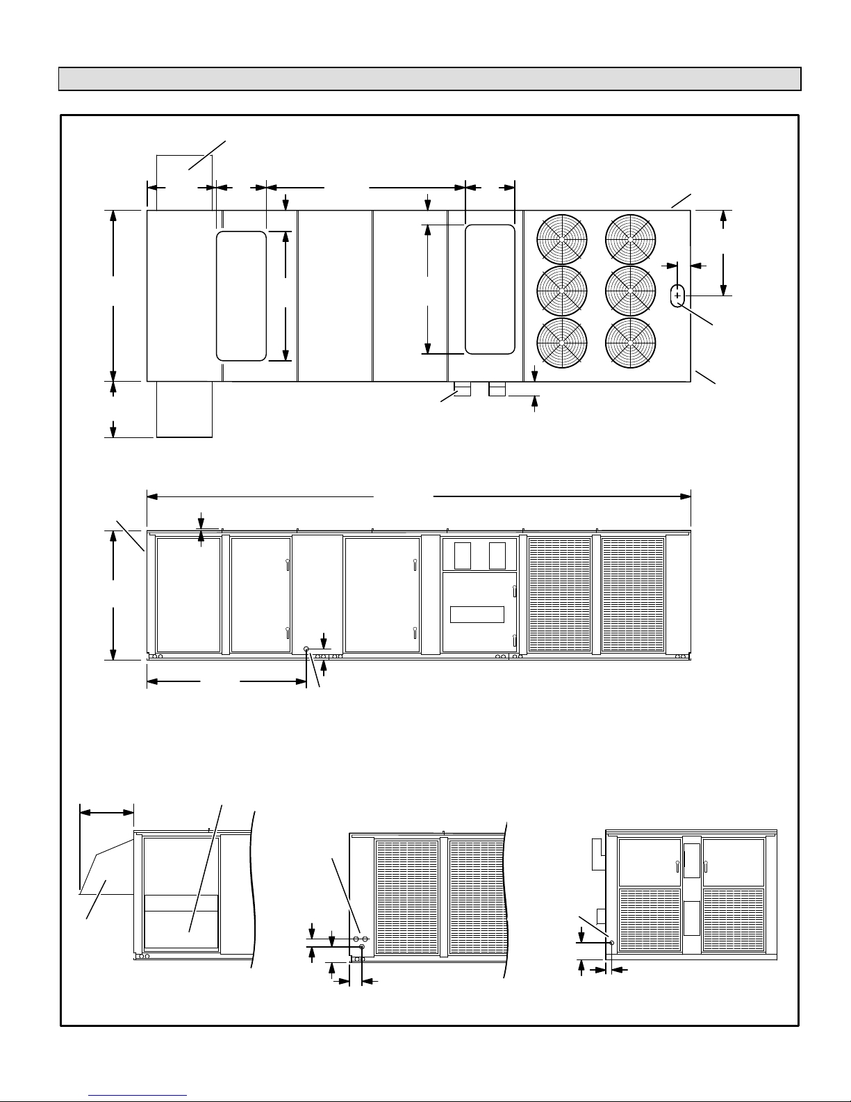
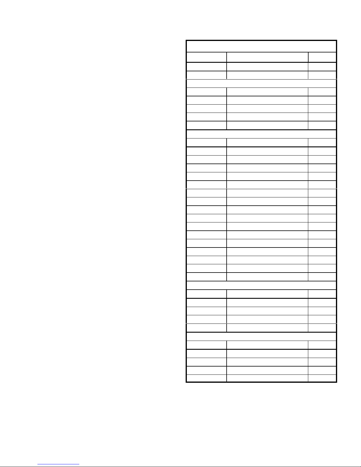
LGH/LCH 420, 480, 540, 600 Unit Dimensions Vertical Airflow - Inches (mm) - Gas Heat Shown
Optional Barometric Relief Hoods (one or two, each side).
NOTE - If only one hood is used it is located on this side of unit.
90
(2286)
28-3/4
(730)
See Optional
Outdoor Air
Hood Detail
36-3/4
(933)
26
(660)
11 (279)
Return
Air
Opening
1 in. (25 mm) Typ.
68
(1727)
104-3/4
(2661)
7-1/2
68
(1727)
Flue Outlets
TOP VIEW - Base Section
286 (7264)
26
(660)
Supply
Air
Opening
6 (152)
6
(152)
See Electrical
Inlet Detail
45
(1143)
5 x 8 in.
(127 x 203 mm)
Bottom
Wiring Inlet
See Gas
Inlet Detail
68
(1727)
28-3/4
(730)
Outdoor
Air Hood
Optional Barometric Relief Hoods (one or two, each side).
NOTE - If only one hood is used it is located on the opposite side.
OPTIONAL OUTDOOR
AIR HOOD DETAIL
82-7/8
(2105)
5-1/2
(140)
Condensate Drain
Electric
Inlet
8-7/8
(225)
3-3/8
(86)
(Either Side)
SIDE VIEW
ELECTRICAL
INLET DETAIL
Gas
Supply
Inlet
13-1/4 (337)
4-7/8
(124)
GAS INLET
DETAIL
Page 2
LGH/LCH420, 480, 540, 600
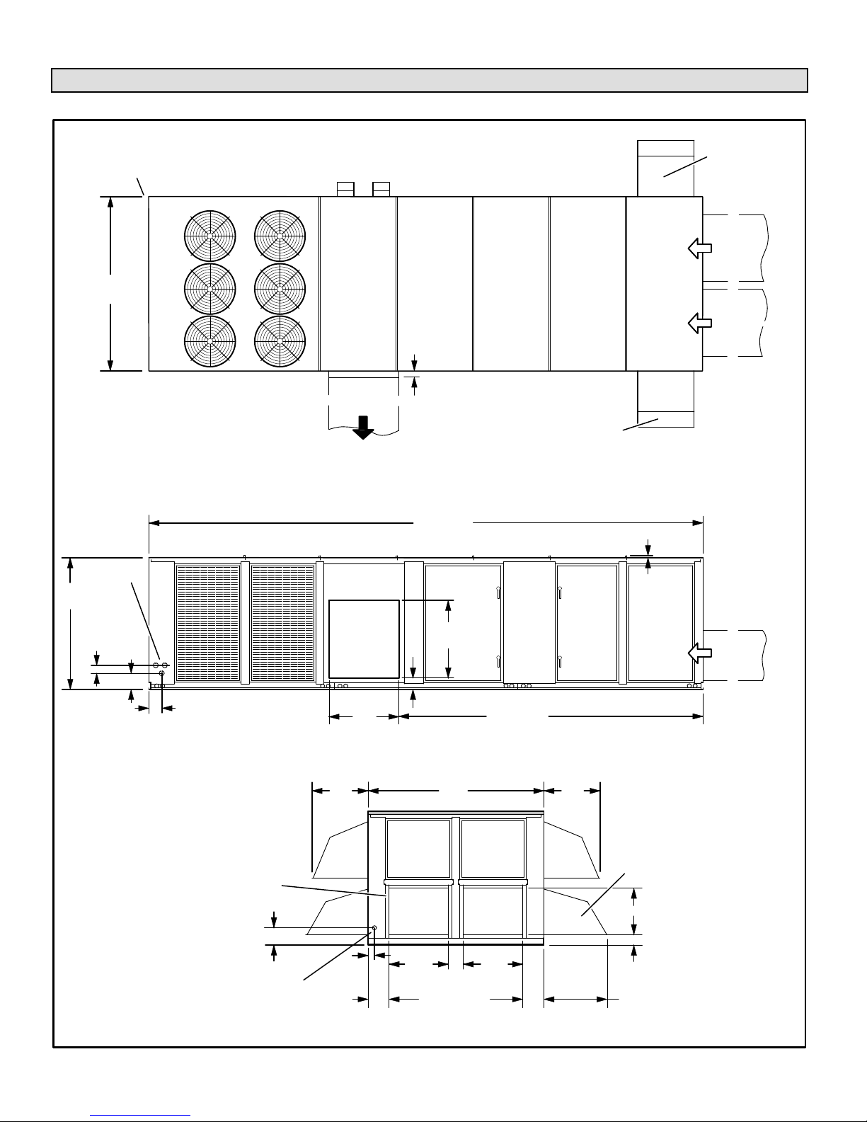
LGH/LCH420, 480, 540, 600 Unit Dimensions Horizontal Airflow - In. (mm) - Gas Heat Shown
Optional
See End View for gas
supply inlet detail
90
(2286)
1-1/2 (38)
(all 4 sides of supply
air opening)
TOP VIEW
Optional Barometric
Relief Hoods
(one or two, each side).
NOTE - If only one hood
is used it is located on
the same side of unit as
the Supply Air Opening.
Outdoor Air
Hoods (2)
Return
Opening
Return
Opening
Air
Air
68
(1727)
Electric
3-3/8
(86)
Inlet
8-7/8
(225)
5-5/8
(143)
1-3/8 in. (35 mm) wide
gasketed seal
recessed 1-1/8 in. (29 mm)
(all 4 sides of each
return air opening)
13-1/4 (337)
Gas
Supply
Inlet
Opening
26-1/4
(667)
4-7/8
(124)
Supply
Air
36
(914)
10-3/8
(264)
286 (7264)
(1016)
6 (152)
SIDE VIEW
(2286)
Return
Air
Opening
31-1/4
(794)
69-1/4 (1759)
END VIEW
40
90
6-3/4
(171)
157 (3988)
Return
Air
Opening
31-1/4
(794)
10-3/8
(264)
26-1/4
(667)
1 in. (25 mm) Typ.
Return
Air
Opening
Optional Barometric
Relief Hoods
(one or two, each side).
NOTE - If only one hood
is used it is located on
the same side of unit as
the Supply Air Opening.
23-3/4 (603)
6-1/4
(159)
28-3/4
(730)
507232-04 7/2017
Page 3

CONTROL
FANS (6)
CONDENSER
BOX
COMPRESSORS (4)
FILTERS
ELEVEN - 16 x 25 x 2”
(406 x 635 x 51mm)
OR
16 X 25 X 4”
(OPTIONAL)
ECONOMIZER
LGH420, 480, 540, 600 PARTS ARRANGEMENT
WHEEL (OPTIONAL)
ENERGY RECOVERY
BLOWERS
(406 X 635 X 102mm)
FILTER
HOT GAS
(OPTIONAL)
REHEAT COILS
BURNERS
DRIERS
GAS VALVES (2)
LOUVERS
(OPTIONAL)
COILS (4)
CONDENSER
Page 4
COILS
EVAPORATOR
(OPTIONAL)
DISCHARGE
POWER EXHAUST
DRAIN
CONDENSATE
LGH/LCH420, 480, 540, 600
Shipping and Packing List
Requirements
Package 1 of 1 contains:
1- Assembled unit
Check unit for shipping damage. Receiving party should
contact last carrier immediately if shipping damage is found.
IMPORTANT - Hot gas reheat units require a specific
field-provided and installed humidity sensor or digital
input. Refer to control wiring section.
General
These instructions are intended as a general guide and do
not supersede local codes in any way. Authorities having
jurisdiction should be consulted before installation.
Use of this unit as a construction heater or air conditioner is
not recommended during any phase of construction. Very
low return air temperatures, harmful vapors and operation
of the unit with clogged or misplaced filters will damage the
unit.
If this unit has been used for heating or cooling of buildings
or structures under construction, the following conditions
must be met or the warranty will be void:
The vent hood must be installed per these installation
instructions.
A room thermostat must control the unit. The use of
fixed jumpers that will provide continuous heating or
cooling is not allowed.
A pre-filter must be installed at the entry to the return air
duct.
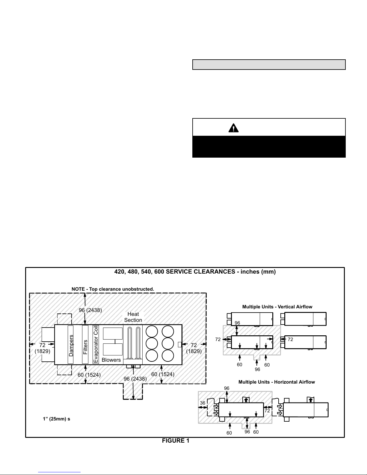
See figure 1 for unit clearances.
WARNING
Electric shock hazard and danger of
explosion. Can cause injury, death or
product or property damage. Turn off
gas and electrical power to unit before
performing any maintenance or
servicing operations on the unit. Follow
lighting instructions attached to unit
when putting unit back into operation
and after service or maintenance.
IMPORTANT
The Clean Air Act of 1990 bans the intentional venting
of refrigerant (CFC's and HCFC's) as of July 1, 1992.
Approved methods of recovery, recycling or reclaim
ing must be followed. Fines and/or incarceration may
be levied for non-compliance.
NOTICE
Roof Damage!
This system contains both refrigerant and oil. Some
rubber roofing material may absorb oil, causing the
rubber to swell. Bubbles in the rubber roofing
material can cause leaks. Protect the roof surface to
avoid exposure to refrigerant and oil during service
and installation. Failure to follow this notice could
result in damage to roof surface.
Unit Support
The return air duct must be provided and sealed to the
unit.
Return air temperature range between 55°F (13°C) and
80°F (27°C) must be maintained.
Air filters must be replaced and pre-filters must be
removed upon construction completion.
The input rate and temperature rise must be set per the
unit rating plate.
The heat exchanger, components, duct system, air
filters and evaporator coil must be thoroughly cleaned
following final construction clean-up.
The unit operating conditions (including airflow, cooling
operation, ignition, input rate, temperature rise and
venting) must be verified according to these installation
instructions.
507232-04 7/2017
CAUTION
As with any mechanical equipment, contact with
sharp sheet metal edges can result in personal injury.
Take care while handling this equipment and wear
gloves and protective clothing.
In downflow discharge installations, install the unit on a
non-combustible surface only. Unit may be installed on
combustible surfaces when used in downflow discharge
applications when installed on an S1CURB10E-1 roof
mounting frame.
NOTE - Securely fasten roof frame to roof per local codes.
CAUTION
To reduce the likelihood of supply / return air bypass
and promote a proper seal with the RTU, duct work /
duct drops / diffuser assemblies must be supported
independently to the building structure.
Page 5
A-Downflow Discharge Application
Roof Mounting with S1CURB10E-1
1- The S1CURB10E-1 roof mounting frame must be
installed, flashed and sealed in accordance with the
instructions provided with the frame.
5- Units require support along all four sides of unit base.
Supports must be constructed of steel or suitably
treated wood materials.
Duct Connection
2- The S1CURB10E-1 roof mounting frame should be
square and level to 1/16” per linear foot (1.6mm per 305
linear mm) in any direction.
3- Duct must be attached to the roof mounting frame and
not to the unit; supply and return plenums must be
installed before setting the unit.
Installer's Roof Mounting Frame
Many types of roof frames can be used to install the unit
depending upon different roof structures. Items to keep in
mind when using the building frame or supports are:
1- The base is fully enclosed and insulated, so an
enclosed frame is not required.
2- The frames or supports must be constructed with
non-combustible materials and should be square and
level to 1/16” per linear foot (1.6mm per 305 linear mm)
in any direction.
3- Frame or supports must be high enough to prevent any
form of moisture from entering unit. Recommended
minimum frame height is 14” (356mm).
4- Duct must be attached to the roof mounting frame and
not to the unit. Supply and return plenums must be
installed before setting the unit.
All exterior ducts, joints and openings in roof or building
walls must be insulated and weather-proofed with flashing
and sealing compounds in accordance with applicable
codes. Any duct passing through an unconditioned space
must be insulated.
CAUTION
In downflow applications, do not drill or punch holes
in base of unit. Leaking in roof may occur if unit base
is punctured.
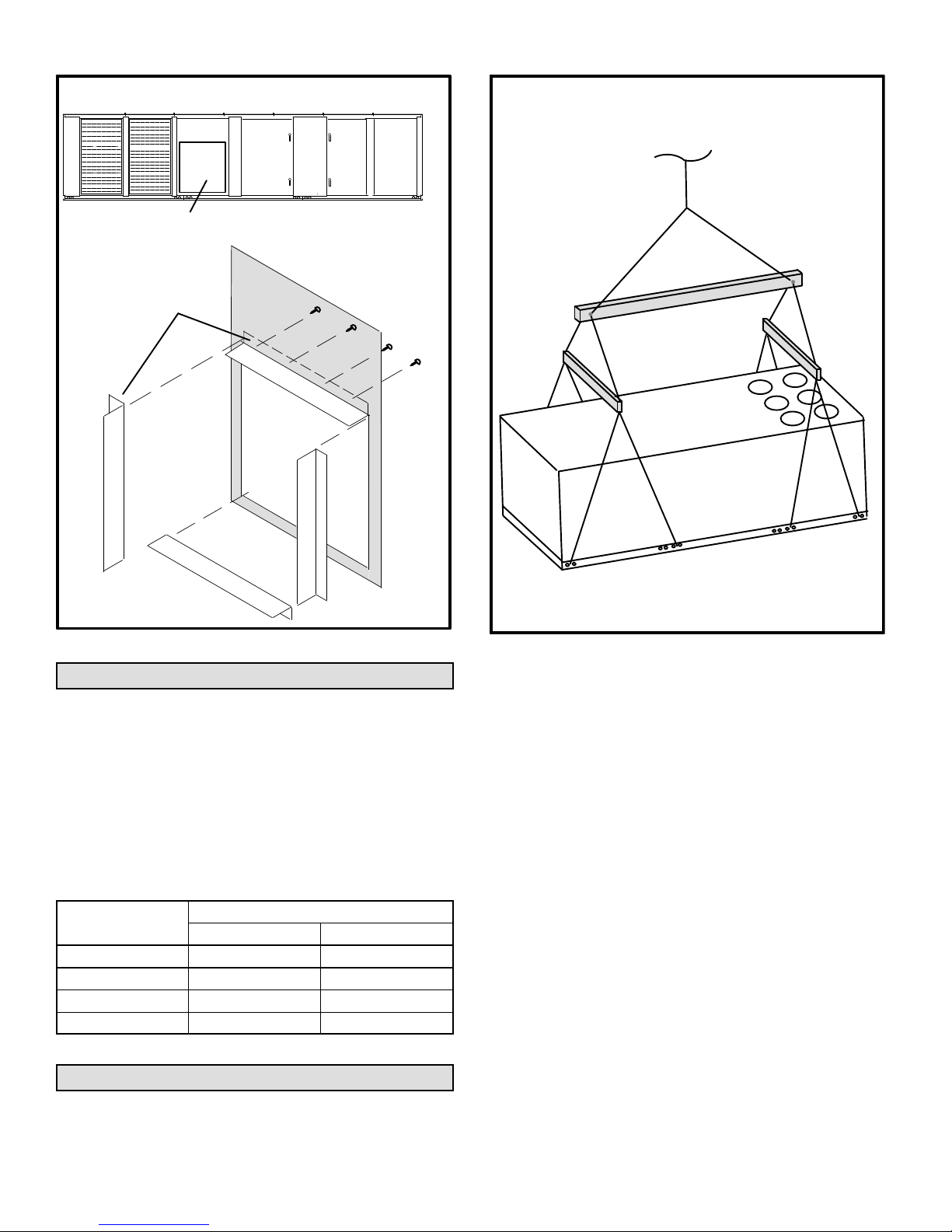
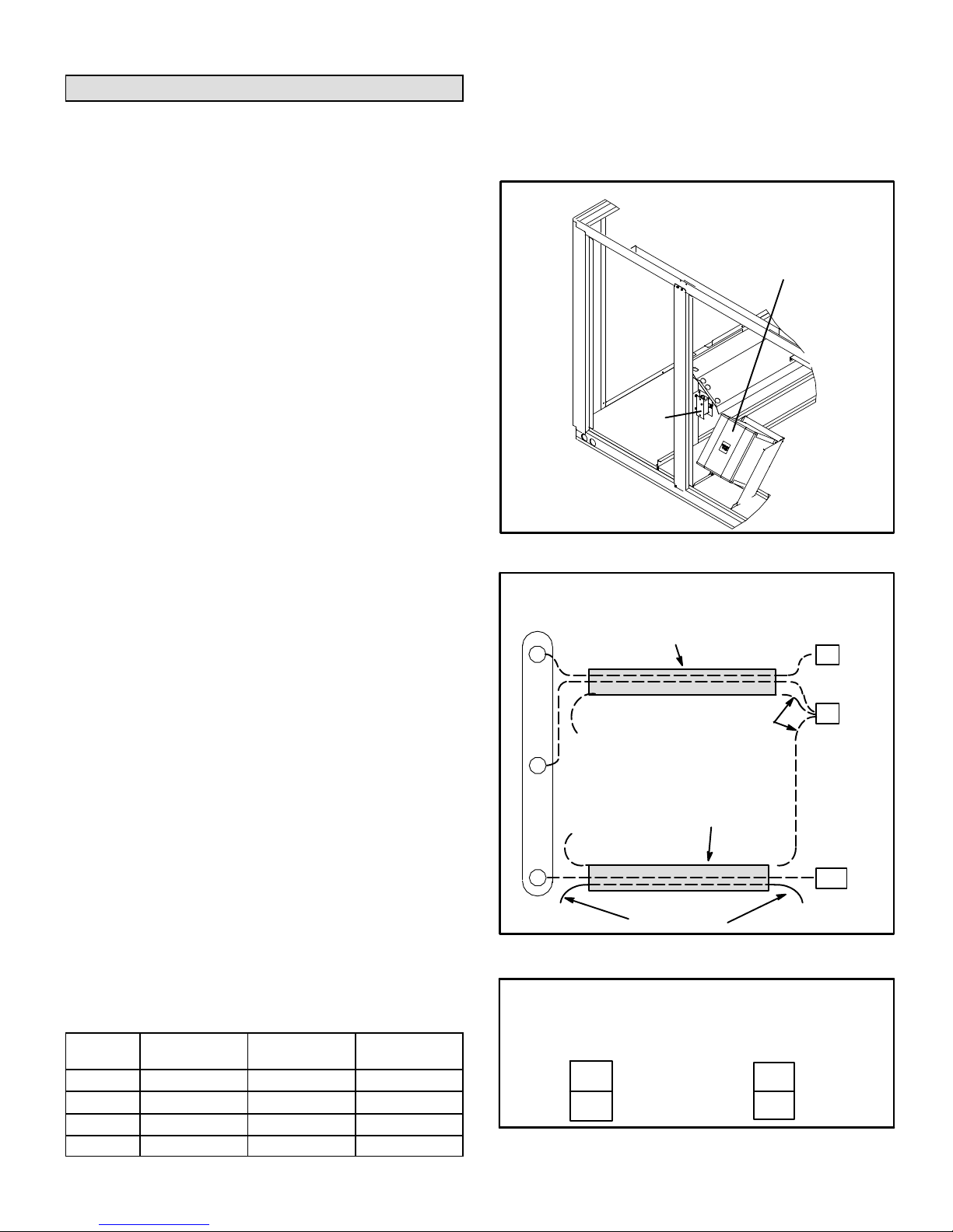
Horizontal Supply Air
1- Locate horizontal discharge air flanges in blower
section.
2- Remove and discard horizontal supply air shipping
cover from supply air panel on back side of unit. See
figure 2.
3- Position flanges as shown in figure 2. Make sure the
narrow side of the flange is positioned on the inside of the
unit panel. Secure with screws from the inside of the unit.
4- Secure ductwork to flanges per applicable codes.
420, 480, 540, 600 SERVICE CLEARANCES - inches (mm)
NOTE - Top clearance unobstructed.
96 (2438)
72
(1829)
1” (25mm) supply duct clearance for a distance of 3' (914m)
is required on LC units equipped with electric heat.
Filters
Dampers
60 (1524)
Blowers
Evaporator Coil
Heat
Section
96 (2438)
60 (1524)
FIGURE 1
72
(1829)
36
72
Multiple Units - Vertical Airflow
96
60
Multiple Units - Horizontal Airflow
96
60
96
60
96
60
72
72
Page 6
LGH/LCH420, 480, 540, 600
HORIZONTAL SUPPLY AIR
BACK OF UNIT
RIGGING UNIT
LIFTING POINT SHOULD BE DIRECTLY
ABOVE CENTER OF UNIT
HORIZONTAL SUPPLY AIR
SHIPPING COVER
INSTALL NARROW
SIDE OF FLANGE
ON THE INSIDE
OF PANEL
FIGURE 2
SECURE FLANGES
WITH SCREWS FROM
INSIDE OF UNIT
CAUTION - Do not
walk on unit.
ALL 8 POINTS MUST BE
USED FOR HOISTING
IMPORTANT - All panel must be in place for rigging.
FIGURE 3
Rigging Unit For Lifting
1- Connect rigging to the unit base rail using holes in each
corner and unit sides. ALL 8 POINTS MUST BE USED
FOR HOISTING. See figure 3.
2- All panels must be secured in place before lifting.
3- Three field-provided spreader bars must be used.
THE LENGTHWISE SPREADER BAR MUST BE AT
LEAST 16 FEET (5 METERS) LONG. The horizontal
spreader bars must be at least 90 inches (2.3m) long
to prevent unit damage.
Maximum Weight*
Unit
420 8545 3875
480 8575 3889
540 8585 3893
600 8600 3900
*Maximum weight with all available factory-installed accessories.
Lbs. Kgs.
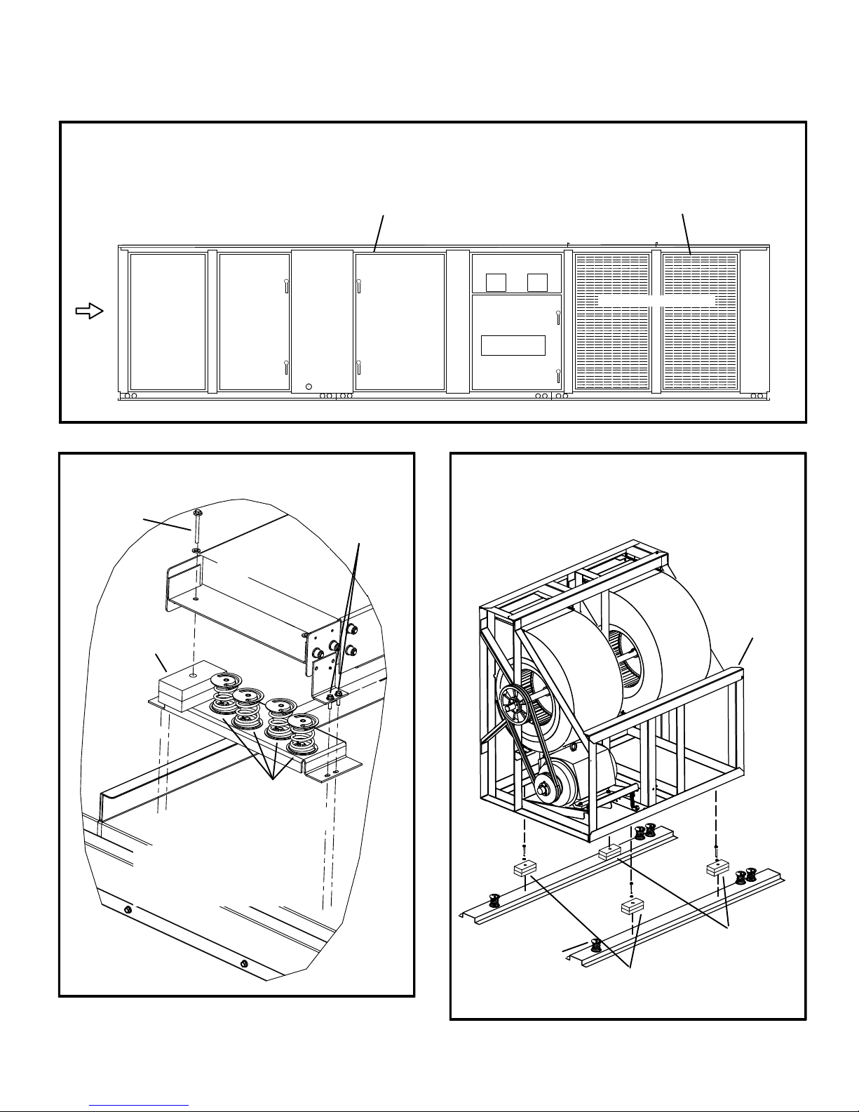
Shipping Blocks
Note - Wooden shipping blocks are installed only in
units equipped with optional factory-installed spring
mounts.
Page 7
Compressor Hat Section Shipping Blocks
1- Remove screws and open front and back hinged
condenser access panels. See figure 4 for panel
location.
2- Remove two shipping blocks beneath the compressor
hat section. Access one shipping block from the front
side of the unit as shown in figure 5. The other shipping
block is located in the same place on the back side of
the unit.
3- Remove shipping screws. See figure 5.
Indoor Blower Shipping Blocks
1- Open front and back blower access panels. See figure
4 for panel location.
2- Remove four shipping blocks and screws located
beneath the indoor blower frame. Access two shipping
blocks from the back side of the unit as shown in figure
6. Access the other two shipping blocks from the same
place on the front side of the unit.
507232-04 7/2017
Power Exhaust Shipping Blocks
1- Open access panels on return end end of unit. See
figure 4.
ACCESS TO COMPRESSOR HAT SECTION AND INDOOR BLOWER SHIPPING BLOCKS
FRONT SIDE OF UNIT SHOWN
2- Remove four shipping blocks and screws beneath the
power exhaust assembly frame as shown in figure 7.
INDOOR BLOWER
SHIPPING BLOCK ACCESS
(BOTH SIDES)
RETURN
AIR END
OF UNIT
Economizer
Section
Blower Motor
Access
Opposite
FIGURE 4
COMPRESSOR HAT SECTION SHIPPING BLOCKS
(FRONT SIDE SHOWN)
REMOVE
SHIPPING
SCREW
REMOVE
SHIPPING
SCREWS
COMPRESSOR
HAT SECTION
Side
COMPRESSOR HAT SECTION
SHIPPING BLOCK ACCESS
(BOTH SIDES)
Heat
Section
Condenser Section
INDOOR BLOWER SHIPPING BLOCKS
(BACK VIEW SHOWN)
Note - Shipping blocks
are only present when
optional spring
mounts are installed.
REMOVE
SHIPPING
BLOCK
Note - Shipping blocks
are only present when
optional spring mounts
are installed.
FIGURE 5
OPTIONAL
SPRING
MOUNTS
OPTIONAL
SPRING MOUNT
(TYPICAL)
BLOCKS AND SCREWS
REMOVE SHIPPING
(BACK SIDE)
FIGURE 6
INDOOR
BLOWER
FRAME
REMOVE SHIP
PING BLOCKS
AND SCREWS
(FRONT SIDE)
Page 8
LGH/LCH420, 480, 540, 600
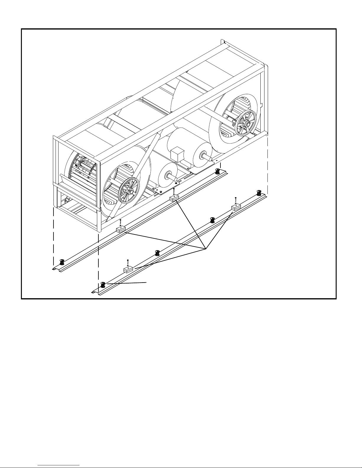
POWER EXHAUST SHIPPING BLOCKS
Note - Shipping blocks are
only present when optional
spring mounts are installed.
OPTIONAL SPRING
MOUNT (TYPICAL)
FIGURE 7
REMOVE SHIPPING
BLOCKS AND SCREWS
507232-04 7/2017
Page 9
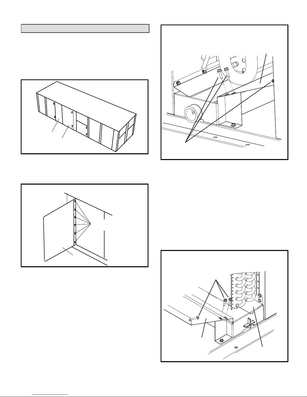
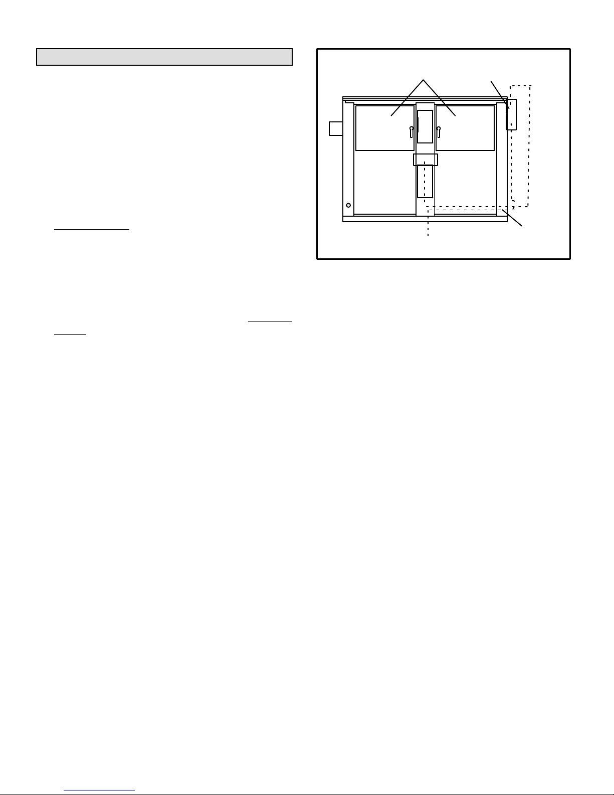
Reverse Condensate Drain Pan
Unit is shipped from the factory with the condensate drain
facing the front of the unit. Reverse drain pan when needed
as follows:
1- Remove blower door on front of unit. See figure 8 and 9.
FRONT MULLION
BLOWER DOOR
FIGURE 8
REMOVE SCREWS SECURING DRIP SHIELD
AND DRAIN PAN
LONG DRIP
SHIELD
REMOVE
SCREWS
FIGURE 10
REMOVE BLOWER DOOR
REMOVE
SCREWS
BLOWER
DOOR
2- Remove and retain the patch plate on the front mullion.
3- Remove front mullion.
4- Remove and retain three screws securing drip shield.
See figure 10.
5- Locate the patch plate on the back mullion. Remove the
patch plate and install on the front mullion.
8- Remove and retain three screws securing drip shields
on back side of unit. See figure 11. Remove long drip
shield.
9- Push the drain pan downward and remove from unit.
10- Rotate the drain pan and reinstall.
11- Reinstall long drip shield with retained screws.
12- Replace mullions and blower door.
REMOVE SCREWS SECURING DRIP SHIELD
AND DRAIN PAN
REMOVE
SCREWS
6- Remove back mullion.
7- Install patch plate from the front mullion on the back
mullion. Position the patch plate in the same location as
the previous patch plate.
LONG DRIP
SHIELD
BACK DRIP
SHIELD
FIGURE 11
Page 10
LGH/LCH420, 480, 540, 600
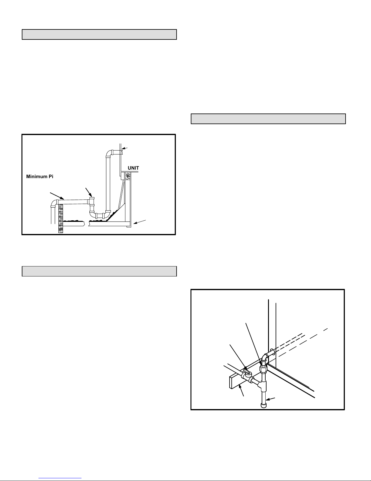
Condensate Drain
Make drain connection to the 1” N.P.T. drain coupling
provided on unit. A trap must be installed between drain
connection and an open vent for proper condensate
removal. See figure 12. It is sometimes acceptable to drain
condensate onto the roof or grade; however, a tee should
be fitted to the trap to direct condensate downward. The
condensate line must be vented. Check local codes
concerning condensate disposal. Refer to pages 1 and 2
for condensate drain location.
CONDENSATE DRAIN CONNECTION
NOTE - Allow clearance to
open doors when installing
condensate piping.
Minimum Pitch
1” (25 mm) per
10' (3 m) of line
OPEN VENT
FIGURE 12
CAULK AROUND
CONDENSATE
COUPLING
UNIT
MOUNTING
FRAME
When making piping connections a drip leg should be
installed on vertical pipe runs to serve as a trap for
sediment or condensate. A 1/8” N.P.T. plugged tap is
located on gas valve for test gauge connection. Refer to
Heating Start-Up section for tap location. Install a ground
joint union between the gas control manifold and the main
manual shut-off valve. See figure 13 for side entry gas
supply piping.
Compounds used on threaded joints of gas piping shall be
resistant to the action of liquified petroleum gases.
Pressure Test Gas Piping
When pressure testing gas lines, the gas valve must be
disconnected and isolated. Gas valves can be
damaged if subjected to more than 0.5 psig (3.5kPa).
See figure 14.
NOTE-Codes may require that manual main shut-off
valve and union (furnished by installer) be installed in gas
line external to unit. Union must be of the ground joint
type.
After all connections have been made, check all piping
connections for gas leaks. Also check existing gas
connections up to the gas valve; loosening may occur during
installation. Use a leak detection solution or other preferred
means. Do not use matches candles or other sources of
ignition to check for gas leaks.
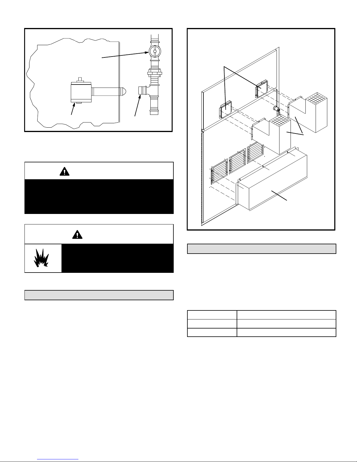
Connect Gas Piping
Two grommets are packaged with the flue exhaust and air
intake hoods located in the gas heat section. Grommets are
installed in the unit entry and gas heat division panel
knockouts. An additional grommet is required when routing
gas piping through the bottom of the unit.
Before connecting piping, check with gas company or
authorities having jurisdiction for local code requirements.
When installing gas supply piping, length of run from gas
meter must be considered in determining pipe size for 0.5”
w.c. (.12kPa) maximum pressure drop. Do not use supply
pipe smaller than unit gas connection. For natural gas
units, operating pressure at the unit gas connection must
be a minimum of 6.0” w.c. (1.5kPa) and a maximum of 14”
(3.50kPa) w.c. For LP/propane gas units, operating
pressure at the unit gas connection must be a minimum of
11” w.c. (2.74kPa) and a maximum of 13.5” w.c. (3.36kPa).
NOTE-In case emergency shut down is required, turn off
the main manual shut-off valve and disconnect main power
to unit. These devices should be properly labeled by the
installer.
SIDE ENTRY OF GAS SUPPLY PIPING
(REFER TO
GROUND
JOINT UNION
MANUAL MAIN
SHUT-OFF VALVE
TO GAS
SUPPLY
GAS PIPING
SUPPORT
LOCAL CODES)
TO GAS
VALV E
DRIP LEG
FIGURE 13
507232-04 7/2017
Page 11
PRESSURE TEST GAS LINE
MANUAL MAIN
SHUT-OFF VALVE
INSTALL EXHAUST AND INTAKE HOODS
REMOVE AND DISCARD
SHIPPING COVERS OVER
EXHAUST OPENINGS
GAS VALVE
FIGURE 14
CAP
CAUTION
Some soaps used for leak detection are corrosive to
certain metals. Carefully rinse piping thoroughly
after leak test has been completed. Do not use
matches, candles, flame or othe sources of ignition
to check for gas leaks.
WARNING
Danger of explosion. Can cause injury
or product or property damage. Do not
use matches, candles, flame or other
sources of ignition to check for leaks.
Flue and Intake Hoods
Hoods are shipped in the gas heat section. Install as shown
in figure 15. Secure with screws provided.
Two grommets are also shipped with the hood assemblies
for gas piping knockouts. Install one grommet in the gas
piping entry knockout. Install the other grommet in the heat
section division panel knockout.
EXHAUST
HOODS
INTAKE
HOOD
FIGURE 15
High Altitude Derate
Locate the high altitude conversion sticker in the unit
literature bag. Fill out the conversion sticker and affix next to
the unit nameplate.
Refer to table 1 for high altitude adjustments.
TABLE 1
HIGH ALTITUDE DERATE
Altitude Ft.* Gas Manifold Pressure
2000-4500 See Unit Nameplate
4500 And Above Derate 4% / 1000 Ft. Above Sea Level
*Units installed at 0-2000 feet do not need to be modified.
NOTE ‐ This is the only permissible derate for these units.
Page 12
LGH/LCH420, 480, 540, 600
Electrical Connections
POWER SUPPLY
Do not apply power or close disconnect switch until
installation is complete. Refer to start-up directions in
Cooling Start-Up section. Refer closely to unit wiring
diagram.
Control Box
2nd Disconnect
Mounting Location
(Dual Power Supply)
Refer to unit nameplate for minimum circuit ampacity and
maximum fuse size.
1-T1 Control Transformer -
Units are factory-wired for 240/460/575 volt supply.
For 208V supply,
remove the insulated terminal cover
from the 208V terminal on the control transformer.
Move the wire from the transformer 240V terminal to
the 208V terminal. Place the insulated terminal cover
on the unused 240V terminal.
2- T18 Contactor Transformer -
230/460/575 volt units are factory wired. For 208V
supply, disconnect the orange wire (230V) at control
power transformer(s). Reconnect the red wire
(208V). Tape the exposed end of the 230V orange
wire.
3- Route electrical supply through the bottom or rear
electric entry area and connect to line side of TB2.
See unit dimensions in the front of this manual. If unit
has optional disconnect or circuit breaker, connect
power wiring to disconnect or circuit breaker. See
unit wiring diagram.
If unit is equipped with optional electric heat and dual
power supply is specified, refer to electric heat wiring
diagram on inside unit panels. See figure 16.
3- Units With Optional Field-Wired 120v GFCI Outlet -
Route and connect separate 120v wiring to GFCI outlets
which do not have factory-installed wiring.
CONTROL WIRING
A-Thermostat Location
Locate thermostat approximately 5 feet (1524mm) above
the floor in an area with good air circulation at average
temperature. Avoid locating the room thermostat where it
might be affected by:
-drafts or dead spots behind doors and in corners
-hot or cold air from ducts
-radiant heat from sun or appliances
-concealed pipes and chimneys
Page 13
TB2
Knockout
Bottom Power Entry
(conduit)
FIGURE 16
B-Wire Routing
Route thermostat cable or wires from subbase through
knockout or bottom power entry area provided in unit. Use
18 AWG wire for all applications using remotely installed
electro-mechanical and electronic thermostats.
IMPORTANT - Unless field thermostat wires are rated for
maximum unit voltage, they must be routed away from line
voltage wiring.
On hot gas reheat units, route wires from RH sensor or
remote switch through knockout or bottom power entry
area. For sensor installations, use 22AWG stranded, two
twisted pairs, individually shielded, 100% aluminum shield
with drain wire and Teflon jacket.
C-Wiring Connections
This unit is equipped with a Unit Controller which controls
unit function. Refer to the Unit Controller manual provided
with each unit.
The Unit Controller will operate the unit from a thermostat,
zone sensor, or zoning system based on the System Mode.
The default System Mode is the thermostat mode. Refer to
the Unit Controller Installation and Setup Guide to change
the System Mode. Use the menu navigation arrows and
select button; see SETTINGS>CONTROL.
1- Default Thermostat Mode -
The Unit Controller will operate two stages of heating
and cooling based on thermostat demands. Install
thermostat assembly in accordance with instructions
provided with thermostat. See figure 17 and wiring
diagrams on unit for field wiring.
IMPORTANT-Terminal connections at the wall plate or
subbase must be made securely. Loose control wire
connections may result in intermittent operation.
507232-04 7/2017

24 VOLT FIELD WIRING IN THERMOSTAT MODE
(Unit Controller in default T'Stat System Mode 6.01 Option 0)
2A2 (2HT/2C)
THERMOSTAT
R
C
G
W1
W2
Y1
Y2
O
UNIT CONTROLLER
24
THERMOSTAT
VAC
G
W1 W2 Y1 Y2
C
R
G
L
O
CP
O
NOTE - ON ELECTRO-ME
CHANICAL THERMOSTATS SET
ANTICIPATOR AT 0.1 AMPS.
Not all terminals
are provided on
all thermostats.
FIGURE 17
UNIT CONTROLLER
24VAC
DI1
RRC R
INPUTSSMOKE
DI2 DI3
Install optional A42
Phase Monitor and/or
S149 Overflow Control
HUMIDISTAT
DI4
C
2- Zone Sensor Mode -
The Unit Controller will operate up to four stages of
heating and cooling based on the Unit Controller
internal setpoints and the temperature from the A2
zone sensor. An optional Network Control Panel (NCP)
24 VOLT FIELD WIRING IN ZONE SENSOR MODE
(Unit Controller in Zone Sensor Mode)
24VAC
RC
SENSOR
AI1
Note - Install sensor and make communication wiring
connections as shown in literature provided with sensor.
UNIT CONTROLLER
IAQ
SENSOR
HUM
TMP
can also be used to provide setpoints. A thermostat or
return air sensor can be used as a back-up mode. See
figure 18 for field wiring.
OUTPUTS
D01
D02
A2 SENSOR
FIGURE 18
Page 14
LGH/LCH420, 480, 540, 600

3- Third-Party Zoning -
The Unit Controller will operate up to four stages of
heating and cooling based on a third-party zoning
system. Only 4 digital inputs are required to control
the rooftop unit: G (blower enable), OCP (occupied),
Y1 (enables discharge cooling) and W1 (enables
discharge heating). Make wiring connections as
shown in figure 19.
24 VOLT FIELD WIRING
FOR UNITS WITH SUPPLY AIR VFD
RTU w/Unit
Controller
G
O
Y1
W1
TB18
3rd Party
Zoning
Control
System
24VAC Digital Signals
Ventilation Demand
Occupied Demand
Cooling Demand
Heating Demand
D-Hot Gas Reheat Units Only -
Install humidity sensor in accordance with instructions
provided with sensor. A DDC input may be used to initiate
dehumidification instead of a sensor. Make wiring
connections as shown in figure 17 for Thermostat Mode
and figure 18 for Zone Sensor Mode. In addition, connect
either a zone sensor or a dehumidification input as shown
in figure 20.
Humidity Sensor Cable Applications:
Wire runs of 50 feet (mm) or less:
Use two separate shielded cables containing 20AWG
minimum, twisted pair conductors with overall shield.
Belden type 8762 or 88760 (plenum) or equivalent.
Connect both cable shield drain wires to TB1-7 as shown in
figure 20.
Wire runs of 150 feet (mm) or less:
Use two separate shielded cables containing 18AWG
minimum, twisted pair conductors with overall shield.
Belden type 8760 or 88760 (plenum) or equivalent.
Connect both cable shield drain wires to TB1-7 as shown in
figure 20.
Supply Static Pr.
Sensor (A30)
R C
CCC
Optional Building Static Pressure
Switch(s) (S37,S39) or Sensor (A34)
FIGURE 19
24 VOLT FIELD WIRING HOT GAS REHEAT UNITS
(Using A Humidity Sensor With Less Than 150 Ft. Wire Runs)
UNIT CONTROLLER
THERMOSTAT
W1
G
G24VAC
L
O
P
Y2
O
Y1
W2
24VAC
A91
HUMIDITY
SENSOR
VIN
IAQ
CR AI1 HUM
TMP
DRAIN
OUTPUTSSENSOR
D01
Wire runs over 150 feet (mm):
Use a local, isolated 24VAC transformer such as Lennox cat
#18M13 (20VA minimum) to supply power to RH sensor as
shown in figure 21. Use two shielded cables containing
20AWG minimum, twisted pair conductors with overall
shield. Belden type 8762 or 88760 (plenum) or equivalent.
HUMIDISTAT
DI4
DI3
C
D02
UNUSED
WIRE
TWISTED
PAIR
INPUTSSMOKE
24VAC
DI1
DI2
RRC R
ENERGY MANAGEMENT SYSTEM
DEHUMIDIFICATION SWITCH
507232-04 7/2017
GND
VOUT
NOT CONNECTED
Install optional A42
Phase Monitor and/or
S149 Overflow Control
FIGURE 20
Page 15
FIELD WIRING HOT GAS REHEAT UNITS
(Using A Humidity Sensor With More
NOT
CONNECTED
A91
VIN
GND
VO
Than 150 Ft. Wire Runs)
ISOLATED 24V
TRANSFORMER
J298A
DRAIN
NOT
CONNECTED
1
2
B
3
4
C
5
6
7
D
8
9
10
FIGURE 21
A55 UNIT
CONTROLLER
P298
R
C
AI-1
HUM
TMP
DO-1
C
DO-2
DI-1
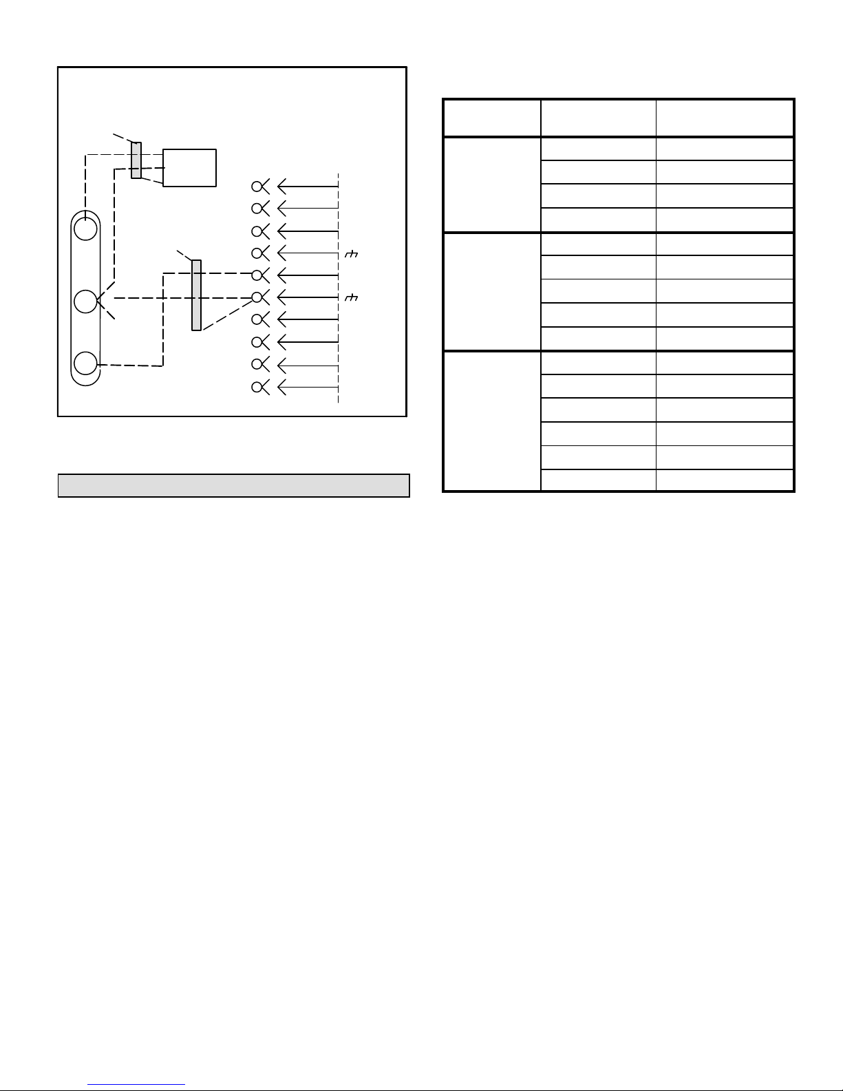
Blower CFM Design Specifications
No. Stages /
Control Type
2 Stages /
Thermostat
3 Stages /
Thermostat
4 Stages /
Room Sensor
OR
Discharge Air
Control
Blower Speed
Htg.
Clg. High
Clg. Low
Ventilation
Htg.
Clg. High
Clg. Med.
2
Clg. Low
Ventilation
Htg.
Clg. High
Clg. Med. High
Clg. Med. Low
Clg. Low
TABLE 2
1
Design
Specified CFM
Multi-Staged Air Volume Start-Up
A-Design Specifications
Use table 2 to fill in field-provided, design specified blower
CFM for appropriate unit.
If only high and low cooling design specifications are
provided, set the medium cooling CFM at the high or low
cooling design spec or any CFM between.
B-Set Maximum CFM
Use table 2 to determine highest blower CFM for
appropriate unit. Adjust the blower pulley to deliver that
amount of CFM with only the blower operating. See
Determining Unit CFM in the Blower Operation and
Adjustment section.
C-Set Blower Speeds
1-Use the following menu to enter the blower design
specified CFM into the Unit Controller. Make sure
blower CFM is within limitations shown in table 3. Refer
to the Unit Controller manual provided with unit.
SETUP > TEST & BALANCE > BLOWER >
2-Enter the following design specifications as shown in
table 2.
Blower / Heat CFM
Cooling High CFM
Cooling Low CFM
Vent CFM
1
1
Page 16
Ventilation
1
Available blower speeds vary by unit and thermostat stages.
2
Requires a transfer relay (K27) and three-stage thermostat.
3-Adjust the blower RPM to deliver the target CFM based
on the measured static pressure using the blower table.
4-Measure the static pressure again and apply the static
pressure and RPM to the blower tables to determine
adjusted CFM.
5-Repeat adjustments until design CFM is reached.
1
The Unit Controller will prompt when more cooling stages
are available depending on the number of compressors and
the control mode.
2
Requires a transfer relay (K27) and three-stage thermostat.
D-Set Damper Minimum Position
To maintain required minimum ventilation air volumes when
the unit is in the occupied mode, two minimum damper
positions must be set. The Unit Controller will open the
dampers to “Min OCP Blwr Low” when blower CFM is
BELOW a “midpoint” CFM. The Unit Controller will open the
damper to “Min OCP Blwr High” when blower CFM is at or
ABOVE the “midpoint” CFM.
The Unit Controller will calculate the “midpoint” CFM.
Set Minimum Position 1
Use the following menu in the Unit Controller to set “Min
OCP Blwr Low” for the blower CFM below the “midpoint”
CFM. When navigating into this menu, the Unit Controller
will bring on the corresponding blower speed and allow
damper position adjustment.
LGH/LCH420, 480, 540, 600
SETTINGS > RTU OPTIONS > EDIT PARAMETER >
ENTER DATA ID - 9 > MIN DAMPER LOW BLOWER =
X.X%
Measure the intake air CFM. If the CFM is lower than the
design specified CFM for ventilation air, use the Unit
Controller to increase the damper percent open. If the
CFM is higher than specified, decrease the damper
percent open.
Note - Intake air CFM can also be determined using the
outdoor air temperature, return air temperature and mixed
air temperature. Refer to the economizer or outdoor air
damper installation instructions.
Set Minimum Position 2
Use the same menu in the Unit Controller to set “Min OCP
Blwr High” for the blower CFM above the “midpoint” CFM.
When navigating into this menu, the Unit Controller will
bring on the corresponding blower speed and allow damper
position adjustment.
SETTINGS > RTU OPTIONS > DAMPER > MIN
DAMPER POSITION BLOWR ON HIGH = X.X%
Measure the intake air CFM. If the CFM is lower than the
design specified CFM for ventilation air, use the Unit
Controller to increase the damper percent open. If the CFM
is higher than specified, decrease the damper percent
open.
Note - Intake air CFM can also be determined using the
outdoor air temperature, return air temperature and mixed
air temperature. Refer to the economizer or outdoor air
damper installation instructions.
E-Inverter Bypass Option
The supply air inverter is factory-set to by-pass the inverter
manually. To by-pass the inverter and operate the blower in
the constant air volume mode, use the following Unit
Controller menu and set to “engaged”:
SETTINGS > RTU OPTIONS > BLOWER > VFD
BYPASS
To configure the unit to by-pass the inverter automatically,
use the following Unit Controller menu.
SETUP > INSTALL
Press SAVE until the menu reads:
CONFIGURATION ID 1
Change the 6
th
character position to A for automatic bypass
option.
Press SAVE
Caution - Units not equipped with an inverter will have the
th
6
character set to N, indicating the inverter is not
bypassed. The blower motor could be damaged and/or
result in product or property damage if the setting is
changed to automatic or manual.
MINIMUM AND MAXIMUM CFM - STAGED BLOWERS
TABLE 3
Gas Heat Minimum CFM
Unit Gas Heat Size Airflow CFM
LGH420-600 Std, Std Mod 9300
LGH420-600 High, High Mod 10800
Electric Heat Minimum CFM
Unit Heat Size (kw) Airflow CFM
LCH420 All 9800
LCH480 All 11200
LCH540 All 12600
LCH600 All 14000
Cooling minimum CFM
Unit Blower Speed Airflow CFM
LGH/LCH420 Cool 1; Clg. Low 5600
Cool 2; Clg. Med. Low 5600
Cool 3; Clg. Med. High 5600
Cool 4; Clg. High 9800
LGH/LCH480 Cool 1; Clg. Low 6400
Cool 2; Clg. Med. Low 6400
Cool 3; Clg. Med. High 6400
Cool 4; Clg. High 11200
LGH/LCH540 Cool 1; Clg. Low 7200
Cool 2; Clg. Med. Low 7200
Cool 3; Clg. Med. High 7200
Cool 4; Clg. High 12600
LGH/LCH600 Cool 1; Clg. Low 8000
Cool 2; Clg. Med. Low 8000
Cool 3; Clg. Med. High 8000
Cool 4; Clg. High 14000
Smoke and Ventilation Minimum CFM
Unit Not Applicable Airflow CFM
LGH/LCH420 NA 5250
LGH/LCH480 NA 6000
LGH/LCH540 NA 6750
LGH/LCH600 NA 7500
Heating and Cooling Maximum CFM
Unit Blower Speed Airflow CFM
LGH/LCH420 High 16800
LGH/LCH480 High 19200
LGH/LCH540 High 21600
LGH/LCH600 High 24000
507232-04 7/2017
Page 17
Variable Air Volume Start-Up
Units may contain an optional supply air blower equipped
with a variable frequency drive A96 (VFD) which varies
supply air CFM.
The supply air VFD (A96) is located near the compressors.
See figure 22.
A-Start-Up
1- A pressure transducer (A30) is shipped in a box in the
blower compartment. Install the transducer according
to manufacturer's instructions.
Note - Make sure the transducer is installed in the main duct
at least 2/3 of the distance away from the unit.
2- Two twisted pairs of shielded cable must be used to
connect the pressure transducer. See figure 23.
3- Open all zone dampers and/or boxes.
4- Locate the A55 Unit Controller in the control box.
5- Use the Unit Controller to calibrate the blower CFM.
Select the SETUP->TEST & BALANCE->BLOWER
menu to start the blower. The Unit Controller will
display the percent of blower speed. Adjust blower
speed percentage to meet design airflow
specifications. Allow blower speed to stabilize.
6- Press SAVE to display the current static pressure. If
the static pressure meets the design specification,
press SAVE again to set the setpoint. If the static
pressure does not meet the design specification,
adjust the pressure and press SAVE to set the
setpoint.
7- Record new setpoints in table 4.
Note - The Unit Controller will lock-out the unit for 5
minutes if static pressure exceeds 2.0”w.c. for 20
seconds. The Unit Controller will permanently shut down
the unit after three occurrences. See Unit Controller
parameters 110, 42, and 43 to adjust default values.
8- If the desired CFM cannot be met with current pulley
setup, refer to the Blower Operation and Adjustments
section to adjust CFM.
B-Unit Operation
Use the Unit Controller to check unit mechanical operation.
See the Service - Test section of the Unit Controller manual.
C-Supply Air VFD By-Pass Plug (Optional)
IMPORTANT - All dampers must be open to prevent
damage to duct work and dampers.
TABLE 4
RECORD ADJUSTED SETPOINTS
Parameter
386 Smoke
387 Ventilation
388 Heating
389 Cooling
Setpoint
Description
Setpoint
“w.c.
Display
Setting
Page 18
The supply air VFD may be by-passed using jack/plug
connections. Locate J/P198 connectors in control box
area under the relays. Disconnect J198 from P198 and
connect J204 to P198. See figure 24. Blower will operate in
constant air volume mode.
SUPPLY AIR VARIABLE FREQUENCY DRIVE
SUPPLY AIR
VFD (A96)
OUTDOOR
AIR
SECTION
OPTIONAL
A34
VIEW SHOWN
FROM FRONT
SIDE OF UNIT
FIGURE 22
PRESSURE TRANSDUCER WIRING
UNIT
DRAIN
CONTROLLER
TB18
6
9
TB24
26
A30
+
_
CONNECTED
+
NOT
CONNECTED
NOT
UNUSED WIRE
TWISTED
PAIR
TWISTED
PAIR
FIGURE 23
SUPPLY AIR VFD BY-PASS CONNECTOR
CONNECTORS USED
FOR SUPPLY AIR
VFD OPERATION
J198
P198
CONNECTORS USED TO BY-PASS
VFD AND OPERATE SUPPLY AIR
BLOWER AT MAXIMUM SPEED
J204
P198
FIGURE 24
LGH/LCH420, 480, 540, 600
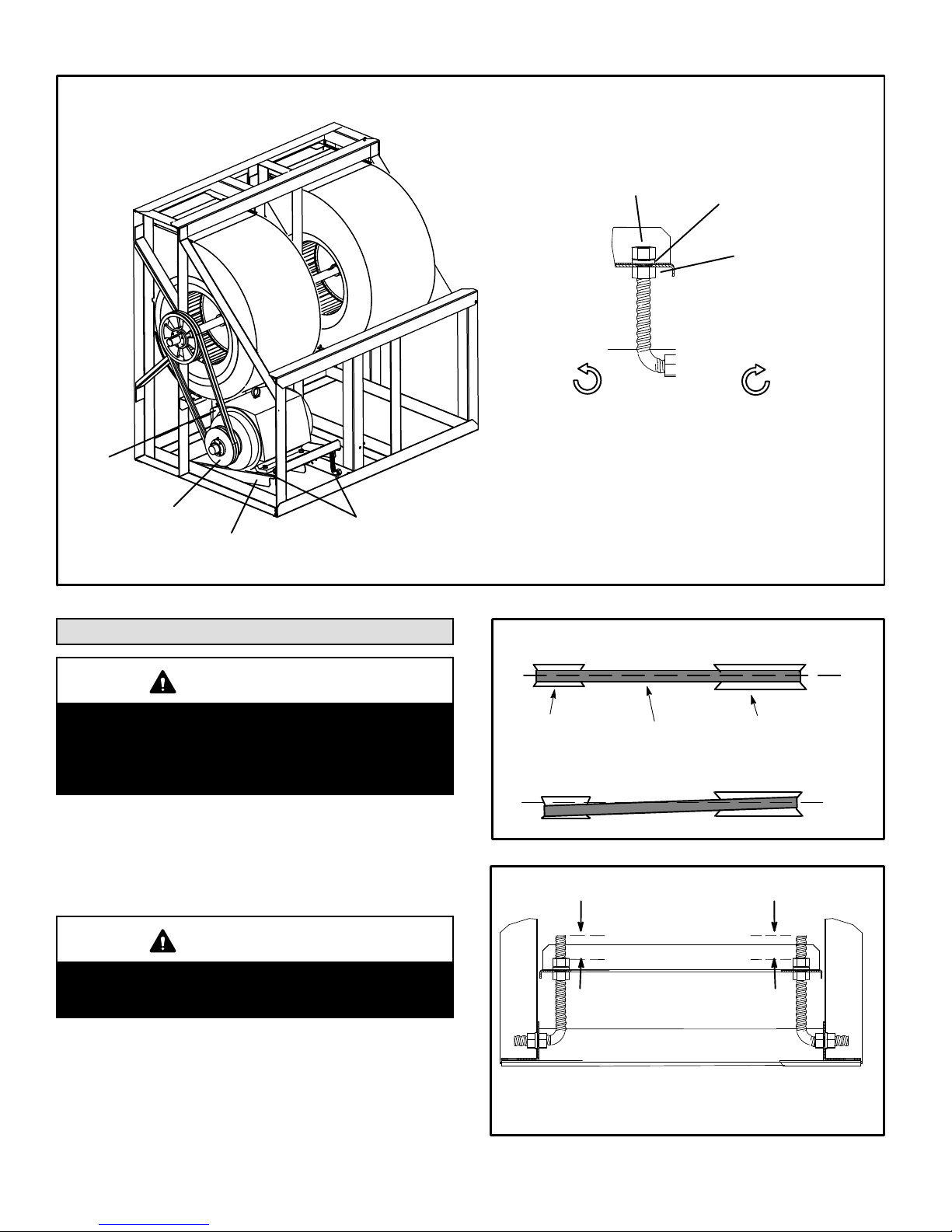
BLOWER ASSEMBLY
UPPER
ADJUSTMENT
NUT
LOCKWASHER
LOWER
ADJUSTMENT
NUT
BLOWER
MOTOR
PULLEY
MOTOR
SUPPORT
PLATE
BELT TENSION
ADJUSTMENT
BOLTS
FIGURE 25
Blower Operation and Adjustments
IMPORTANT
Three phase scroll compressors must be phased se
quentially for correct compressor and blower rota
tion. Follow “COOLING START-UP” section of instal
lation instructions to ensure proper compressor and
blower operation.
A-Blower Belt Adjustment
Maximum life and wear can be obtained from belts only if
proper pulley alignment and belt tension are maintained.
Tighten belt as shown in figure 25.
TO LOOSEN BELT
Turn upper nut on both ad
justment bolts counter
clockwise. Secure support
plate with lower nuts.
TO TIGHTEN BELT
Turn lower nuts on both
adjustment bolts clock
wise. Secure support
plate with upper nuts.
PULLEY ALIGNMENT
ALIGNED
BLOWER
PULLEY
BELT
NOT ALIGNED
FIGURE 26
BLOWER MOTOR SUPPORT PLATE
MOTOR
PULLEY
IMPORTANT
After a 24-48 hour period of operation, tighten new
belts again. This will allow belt to stretch and seat
into grooves.
Make sure blower and motor pulley are aligned as shown in
figure 26. Also make sure motor support plate is level. See
figure 27.
507232-04 7/2017
Measure the position of the nuts on the adjusting
screw to make sure the support plate is level.
Tighten upper and lower adjustment nuts.
FIGURE 27
Page 19
 Loading...