

2017
INSTALLATION
WARNING
Improper installation, adjustment, alteration, ser
vice or maintenance can cause property damage,
personal injury or loss of life. Installation and ser
vice must be performed by a licensed professional
HVAC installer or equivalent, service agency, or the
gas supplier
CAUTION
As with any mechanical equipment, contact with
sharp sheet metal edges can result in personal in
jury. Take care while handling this equipment and
wear gloves and protective clothing.
Table of Contents
Dimensions Page 2.................................
Parts Arrangements Page 5.........................
Shipping and Packing List Page 6....................
General Page 6....................................
Unit Support Page 7................................
Duct Connection Page 8............................
Rigging Unit For Lifting Page 8.......................
Condensate Drains Page 8..........................
Gas Piping Page 9.................................
Pressure Test Gas Piping Page 10.....................
High Altitude Derate Page 10.........................
Electrical Connections Page 10.......................
INSTRUCTIONS
LGH/LCH156H
LGH/LCH180H
LGH/LCH180U
LGH/LCH210H
LGH/LCH240H
LGH/LCH240U
LGH/LCH300S
ROOFTOP PACKAGED UNITS
507124-05
12/2017
Supersedes 11/2017
Blower Operation and Adjustments Page 13............
Cooling Start-Up Page 20............................
Gas Heat Start-Up Page 40...........................
Heating Operation and Adjustments Page 42............
Electric Heat Start-Up Page 42........................
Supply Air Inverter Start-Up Page 42...................
Supply Air Inverter Operation Page 46.................
Hot Gas Reheat Operation and Start-Up Page 48........
Service Page 52....................................
Unit Controller Parameter Settings Page 54.............
(13 Ton)
(15 Ton)
(15 Ton)
(17.5 Ton)
(20 Ton)
(20 Ton)
(25 Ton)
RETAIN THESE INSTRUCTIONS FOR FUTURE REFERENCE
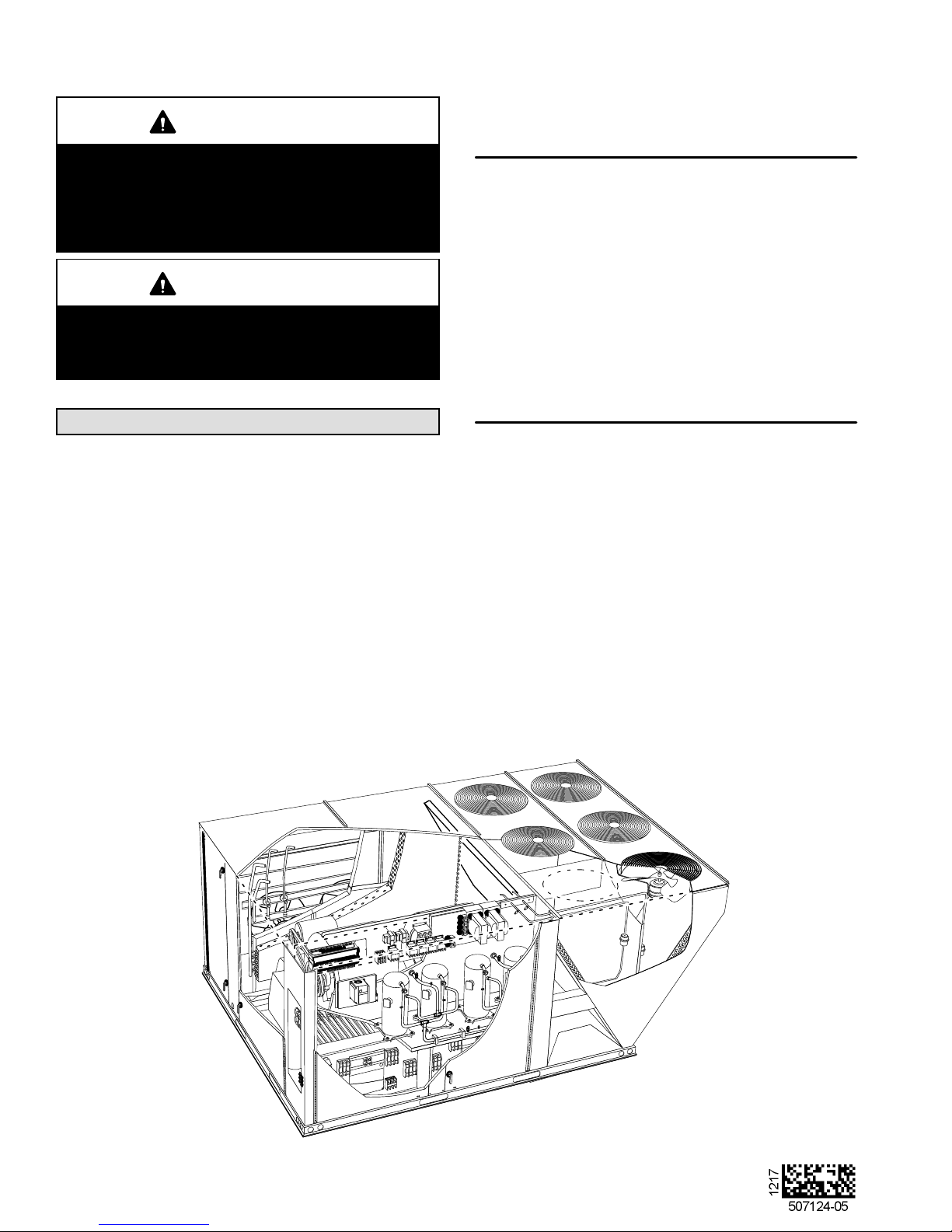
LCH180U SHOWN
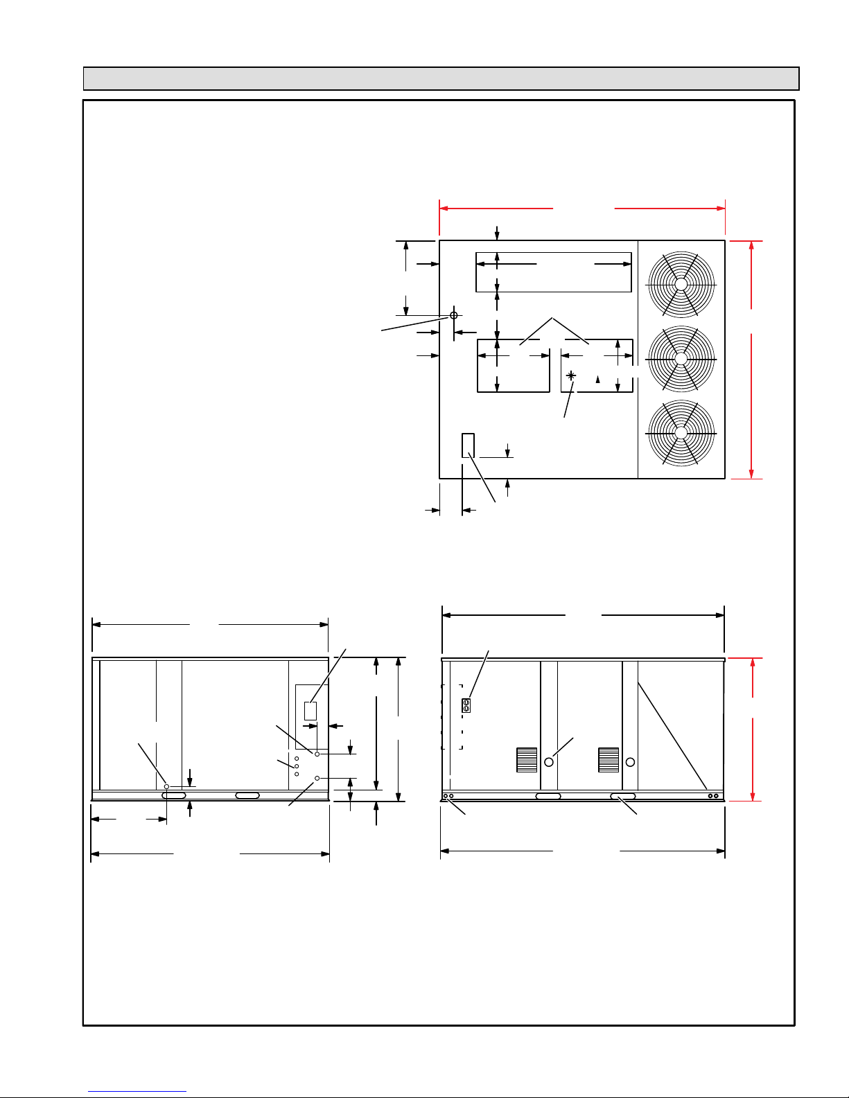
LGH/LCH156 Unit Dimensions - Inches (mm) - Gas Heat Section Shown
)
107−3/4
BASE
4−1/4 (108)
ALTERNATE (THRU THE BASE)
CONDENSA
TE DRAIN LOCATION
1−5/8 in. (41 mm) Diameter
28−3/8
(721)
5−5/8 (143)
12−3/8
(314)
12−3/8
(314)
15 (381)
18 (457)
20 (508) 20 (508)
(102)
60−1/2 (1537)
BOTTOM RETURN
AIR OPENING
BOTTOM SUPPL
AIR OPENINGS
4−1/2
(114)
28
(71
1)
CENTER OF
GRAVITY
4
(2737)
Y
28
(71
91−1/8 (2315
BASE
1)
CONDENSA
DRAIN
28−3/4
(730)
90−1/8
(2289)
TE
91−1/8 (2315)
BASE
END VIEW
GAS SUPPLY INLET
SIDE
ELECTRICAL
INLETS
5−3/8
(137)
GAS SUPPLY OUTLET
(For Bottom
Gas Supply Only)
OPTIONAL
DISCONNECT
(Factory Installed)
51
(1295)
4
54−1/4
(102)
(1378)
10−1/4
(260)
8−1/4
(210)
3−1/4
(83)
4
(102)
BOTTOM POWER ENTRY
5 X 8 inches (127 X 203 mm)
OPTIONAL
115 VOLT OUTLET
(Factory Installed Inside Unit)
OUT LET
LIFTING HOLES
(For Rigging
Front and Back)
107−3/4(2737)
SIDE VIEW
TOP VIEW
106−1/2
(2705)
FLUE
FORKLIFT SLOTS
(Front and Left Side Only)
BASE
54−1/4
(1378)
LGH/LCH156, 180, 210, 240, 300S
Page 2
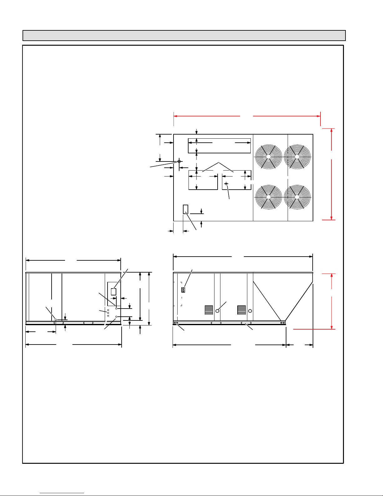
LGH/LCH180H Unit Dimensions - Inches (mm) - Gas Heat Section Shown
133−1/8
(3394)
CONDENSA
DRAIN
90−1/8
(2289)
GAS SUPPLY INLET
TE
5−3/8
(137)
ALTERNATE (THRU THE BASE)
CONDENSA
TE DRAIN LOCATION
1−5/8 in. (41 mm) Diameter
SIDE
ELECTRICAL
INLETS
OPTIONAL
DISCONNECT
(Factory Installed)
51
(1295)
4
(102)
54−1/4
10−1/4
(1378)
(260)
AA
28−3/8
(721)
5− 5/8 (143)
DD
4
(102)
4−1/4 (108)
12−3/8
(314)
15 (381)
18 (457)
12−3/8
(314)
20 (508)
(102)
BOTTOM POWER EN TRY
5 X 8 inches (127 X 203 mm)
OPTIONAL
115 VOLT OUTLET
(Factory Installed Inside Unit)
60−1/2 (1537)
BOTTOM RETURN
BOTTOM SUPPL
AIR OPENINGS
28
1)
(71
4
CENTER OF
AIR OPENING
4−1/2
(114)
GRAVITY
(711)
132−5/8
(3369)
FLUE
OUT LET
Y
28
20 (508)
TOP VIEW
BB
CC
91−1/8
(2315)
54−1/4
(1378)
28−3/4
(730 )
GAS SUPPLY OUTLET
91−1/8 (2315)
BASE
(For Bottom
Gas Supply Only)
8−1/4
(210)
END VIEW
3−1/4
(83)
LIFTINGHOLES
(For Rigging
Front and Back)
Page 3
FOR KLIFT SLOTS
(Front and Left Side Only)
(2737)
107−3/4
BASE
SIDE VIEW
25−3/8
(645)
507124-04 3/2016
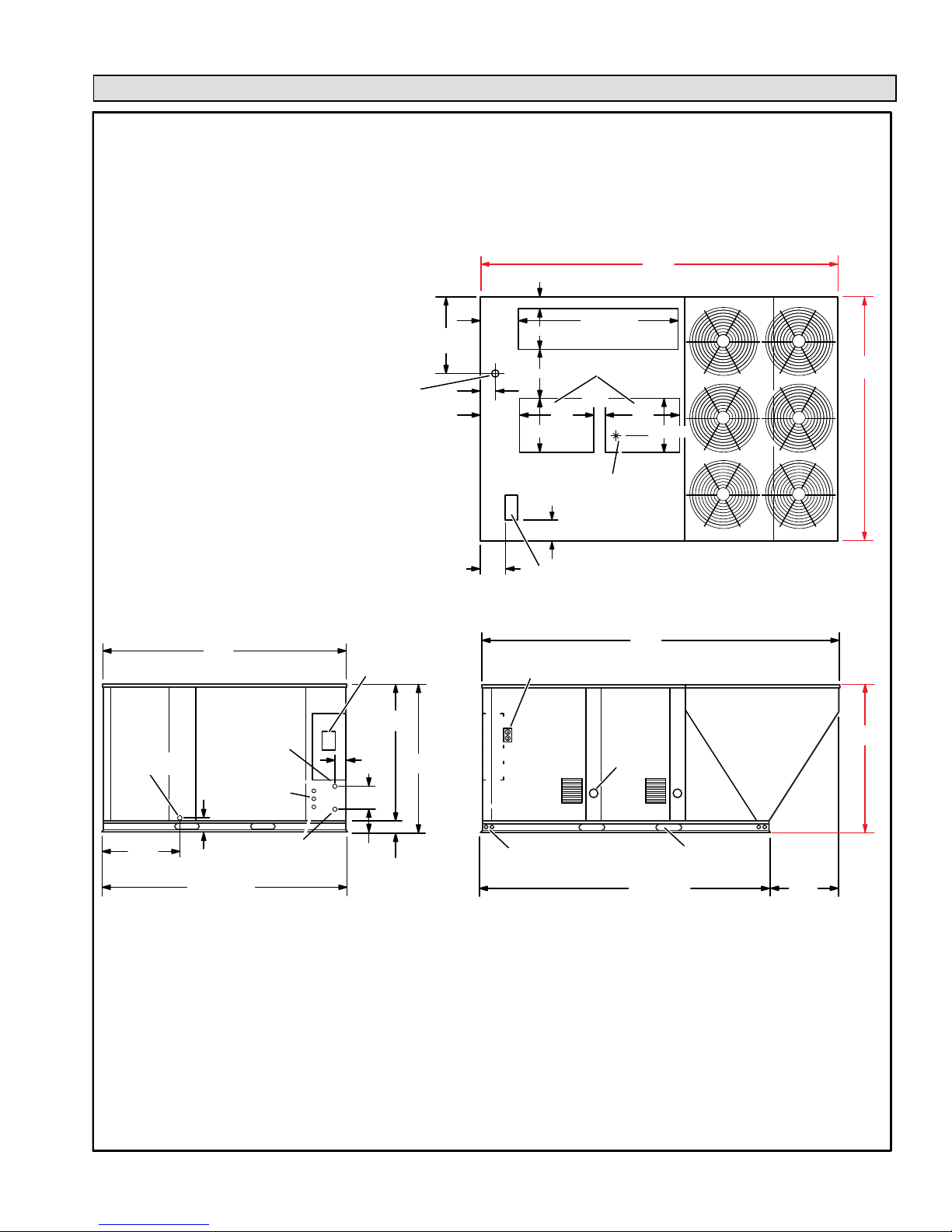
LGH/LCH180U, 210, 240H/U & 300S Unit Dimensions - Inches (mm) - Gas Heat Section Shown
133−1/8
(3381)
BB
CC
ALTERNATE (THRU THE BASE)
CONDENSA
TE DRAIN LOCATION
1−5/8 in. (41 mm) Diameter
AA
28−3/8
(721)
5−5/8 (143)
DD
4
(102)
4−1/4 (108)
12−3/8
(314)
15 (381)
BOTTOM SUPPL
AIR OPENINGS
18 (457)
12−3/8
(314)
28
(711)
20 (508)
4
(102)
BOTTOM POWER ENTRY
5 X 8 inches (127 X 203 mm)
60−1/2 (1537)
BOTTOM RETURN
AIR OPENING
Y
4−1/2
(114)
CENTER OF
GRAVITY
28
(711)
20 (508)
TOP VIEW
91−1/8
(2315)
CONDENSA
DRAIN
28−3/4
(730)
90−1/8
(2289)
GAS SUPPLY INLET
TE
5−3/8
(137)
91−1/8 (2315)
BASE
END VIEW
SIDE
ELECTRICAL
INLETS
GAS SUPPLY OUTLET
(For Bottom
Gas Supply Only)
OPTIONAL
DISCONNECT
(Factory Installed)
51
(1295)
4
54−1/4
(102)
(1378)
10−1/4
(260)
8−1/4
(210)
3−1/4
(83)
OPTIONAL
115 VOLT OUTLET
(Factory Installed Inside Unit)
FLUE
FLUE
OUT LET
OUT LET
LIFTINGHOLES
(For Rigging
Front and Back)
132−5/8
(3369)
FORKLIFT SLOTS
(Front and Left Side Only)
(2737)
107−3/4
BASE
SIDE VIEW
25−3/8
(645)
54−1/4
(1378)
LGH/LCH156, 180, 210, 240, 300S
Page 4
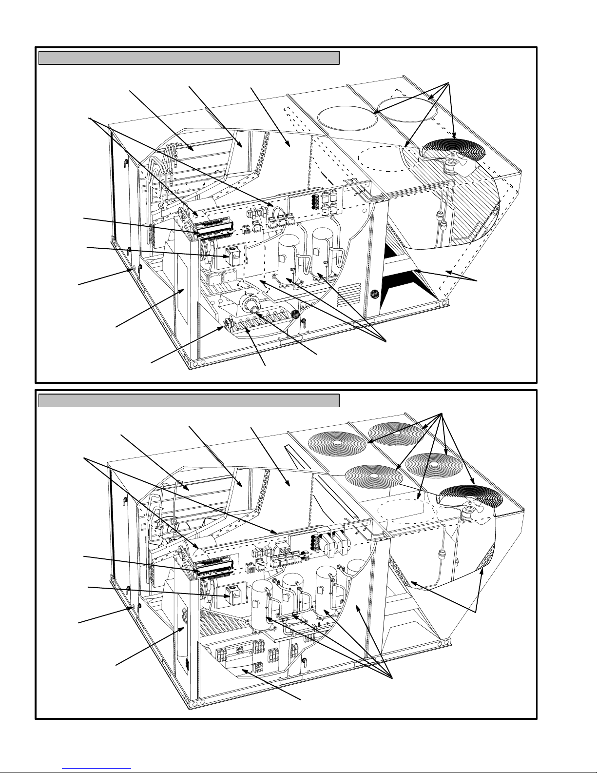
LGH156, 180H/U, 210, 240H/U, 300S PARTS ARRANGEMENT
ECONOMIZER
DAMPERS (OPTIONAL)
BLOWERS
UNIT
CONTROLLER
INVERTER
(OPTIONAL)
CONDENSATE
DRAIN
FILTERS
(SIX - 24 X 24 X 2”)
EVAPORATOR
COIL
180H Shown
CONDENSER FANS
(3 FANS ON 156 UNITS; 6
FANS ON 180U, 210, 240H/U,
& 300S UNITS
CONDENSER
COILS
DISCONNECT
(Factory-installed option)
COMBUSTION
GAS VALVE
BURNERS
AIR INDUCER
LCH156, 180H/U, 210, 240H/U, 300S PARTS ARRANGEMENT
ECONOMIZER
DAMPERS (OPTIONAL)
BLOWERS
UNIT
CONTROLLER
INVERTER
(OPTIONAL)
FILTERS
(SIX - 24 X 24 X 2”)
EVAPORATOR
COIL
180U Shown
COMPRESSORS
(4 ON 180U, 240H/U &
300S UNITS)
CONDENSER FANS
(3 FANS ON 156 UNITS;
4 FANS ON 180H UNITS
CONDENSATE
DRAIN
DISCONNECT
(Factory-installed option)
CONDENSER
COILS
COMPRESSORS
(3 ON 156, 180H & 210 UNITS)
ELECTRIC
HEAT
Page 5
507124-04 3/2016
Shipping and Packing List
Package 1 of 1 contains:
1- Assembled unit
Check unit for shipping damage. Receiving party should
contact last carrier immediately if shipping damage is found.
IMPORTANT - Hot gas reheat units require a specific
field-provided and installed humidity sensor.
General
These instructions are intended as a general guide and
do not supersede local codes in any way. Authorities
having jurisdiction should be consulted before
installation.
Units use R410A, an ozone-friendly HFC refrigerant.
Refer to the Cooling Start-Up section for precautions
when installing unit.
WARNING
Electric shock hazard and danger of
explosion. Can cause injury, death or
product or property damage. Turn off
gas and electrical power to unit before
performing any maintenance or
servicing operations on the unit. Follow
lighting instructions attached to unit
when putting unit back into operation
and after service or maintenance.
The LGH156H gas/electric packaged rooftop unit is
available in 260,000 & 360,000 Btuh heating input. The
LGH180H/U, 210H, 240H/U, & 300S gas/electric
packaged rooftop units are available in 260,000,
360,000, or 480,000 Btuh heating inputs.
The LCH156H, 180H/U, 210H, 240H/U, & 300S cooling
packaged rooftop unit is the same basic design as the
LGH unit except for the heating section. Optional electric
heat is factory- or field-installed in LCH units.
LGH and LCH156H, 180H, 210H, 240H, & 300S units
have identical refrigerant circuits with respective 13, 15,
17‐1/2, 20 and 25 ton cooling capacities. 156H, 180H and
210H units contain three compressors; 240H and 300S
units contain four compressors.
LGH and LCH180U & 240U ultra high efficiency units
have identical refrigerant circuits with respective 15 and
20 ton cooling capacities. Ultra high efficiency units
contain four compressors; compressor 1 & 2 are tandem
and compressor 3 & 4 are tandem.
Standard and high efficiency units come standard with
a lightweight, all-aluminum condenser coil. Standard
and high efficiency units are available with an optional,
factory-installed fin/tube condenser coil. Ultra high
efficiency units are equipped with fin/tube condenser
coils.
Standard and high efficiency units are available with an
optional hot gas reheat coil which provides a
dehumidifying mode of operation. Refer to Reheat
Operation section.
Units equipped with a supply air inverter are available.
Inverters are standard on ultra high efficiency units and
optional on standard and high efficiency units. The blower
will operate at lower speeds when demand is low and
increase to higher speeds when demand is high. Refer to
Inverter Start-Up section.
LGH/LCH156, 180, 210, 240, 300S
Page 6
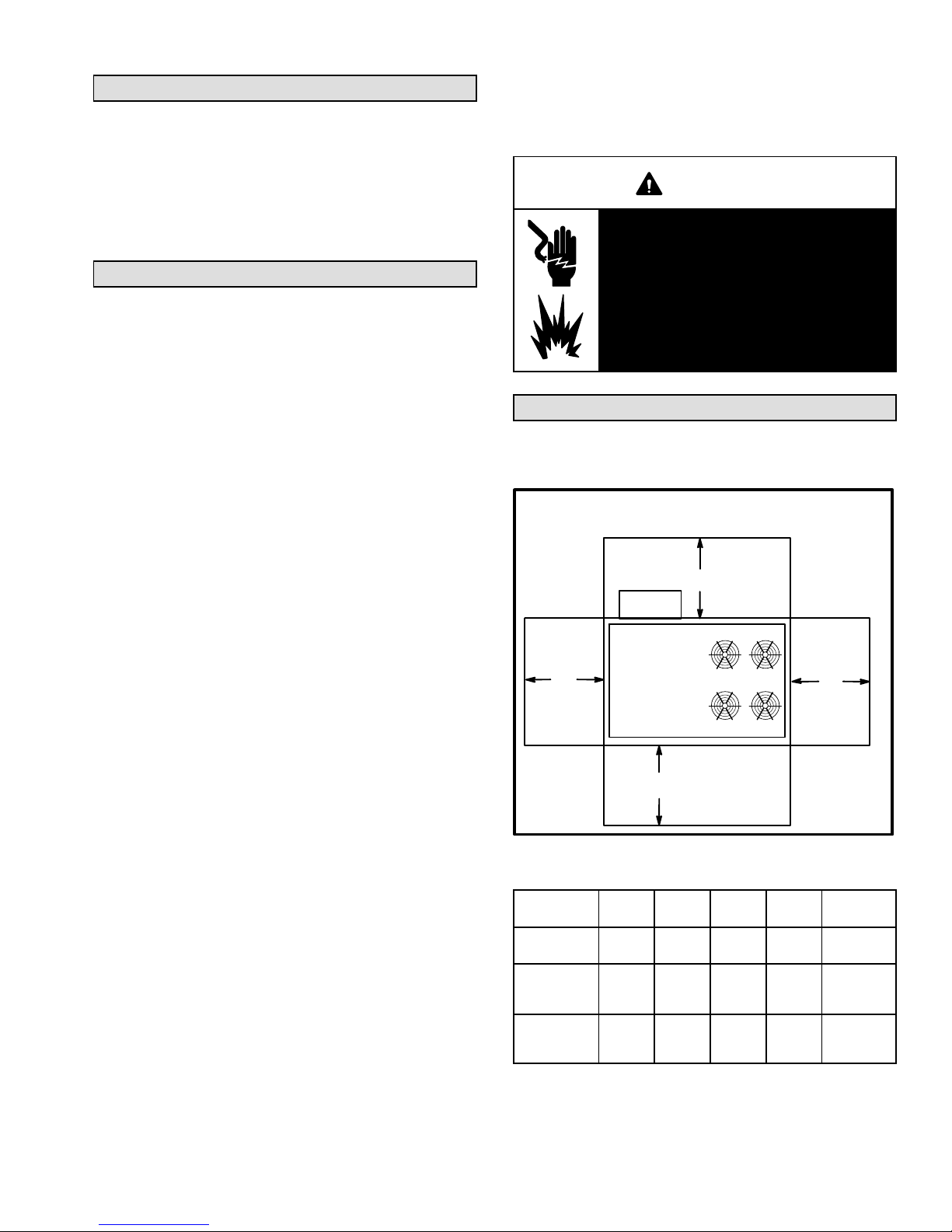
Requirements
See figure 1 for unit clearances.
UNIT CLEARANCES
180H UNIT SHOWN
Optional
Outdoor
Air Hood
D
1
Unit
Clearance
Service
Clearance60(1524)36(914)36(914)66(1676)
Clearance to
Combus
tibles
Minimum
Operation
Clearance
Note - Entire perimeter of unit base requires support when elevated above
mounting surface.
1
Service Clearance - Required for removal of serviceable parts.
Clearance to Combustibles - Required clearance to combustible material
(gas units).
Minimum Operation Clearance - Required clearance for proper unit operation.
A
in.(mm)Bin.(mm)Cin.(mm)Din.(mm)
36
(914)
36
(914)36(914)36(914)41(1041)
C
A
FIGURE 1
1 (25) 1 (25) 1 (25)
B
To p
Clearance
Unob
structed
Unob
structed
Unob
structed
NOTICE
Roof Damage!
This system contains both refrigerant and oil.
Some rubber roofing material may absorb oil,
causing the rubber to swell. Bubbles in the rubber
roofing material can cause leaks. Protect the roof
surface to avoid exposure to refrigerant and oil
during service and installation. Failure to follow
this notice could result in damage to roof surface.
Use of this unit as a construction heater or air conditioner
is not recommended during any phase of construction.
Very low return air temperatures, harmful vapors and
operation of the unit with clogged or misplaced filters will
damage the unit.
If this unit has been used for heating or cooling of
buildings or structures under construction, the following
conditions must be met or the warranty will be void:
The vent hood must be installed per these installation
instructions.
A room thermostat must control the unit. The use of
fixed jumpers that will provide continuous heating or
cooling is not allowed.
A pre-filter must be installed at the entry to the return
air duct.
The return air duct must be provided and sealed to
the unit.
Return air temperature range between 55°F (13°C)
and 80°F (27°C) must be maintained.
Air filters must be replaced and pre-filters must be
removed upon construction completion.
The input rate and temperature rise must be set per
the unit rating plate.
The heat exchanger, components, duct system, air
filters and evaporator coil must be thoroughly
cleaned following final construction clean-up.
The unit operating conditions (including airflow,
cooling operation, ignition, input rate, temperature
rise and venting) must be verified according to these
installation instructions.
Unit Support
In downflow discharge installations, install the unit on a
non-combustible surface only. Unit may be installed on
combustible surfaces when used in horizontal discharge
applications or in downflow discharge applications when
installed on an LARMF18/36 roof mounting frame.
NOTE - Securely fasten roof frame to roof per local codes.
CAUTION
To reduce the likelihood of supply / return air by
pass and promote a proper seal with the RTU, duct
work / duct drops / diffuser assemblies must be
supported independently to the building structure.
A-Downflow Discharge Application
Roof Mounting with LARMF18/36
1- The LARMF roof mounting frame must be installed,
flashed and sealed in accordance with the
instructions provided with the frame.
2- The LARMF roof mounting frame should be square
and level to 1/16” per linear foot (5mm per linear
meter) in any direction.
3- Duct must be attached to the roof mounting frame
and not to the unit; supply and return plenums must
be installed before setting the unit.
Installer's Roof Mounting Frame
Many types of roof frames can be used to install the unit
depending upon different roof structures. Items to keep
in mind when using the building frame or supports are:
1- The base is fully enclosed and insulated, so an
enclosed frame is not required.
2- The frames or supports must be constructed with
non-combustible materials and should be square and
level to 1/16” per linear foot (5mm per linear meter)
in any direction.
3- Frame or supports must be high enough to prevent
any form of moisture from entering unit.
Recommended minimum frame height is 14”
(356mm).
4- Duct must be attached to the roof mounting frame
and not to the unit. Supply and return plenums must
be installed before setting the unit.
IMPORTANT
The Clean Air Act of 1990 bans the intentional vent
ing of refrigerant (CFC's and HCFC's) as of July 1,
1992. Approved methods of recovery, recycling or
reclaiming must be followed. Fines and/or incar
ceration may be levied for non-compliance.
5- Units require support along all four sides of unit base.
Supports must be constructed of steel or suitably
treated wood materials.
NOTE-When installing a unit on a combustible surface for
downflow discharge applications, an LARMF18/36 roof
mounting frame is required.
Page 7
507124-04 3/2016
B-Horizontal Discharge Applications
1- Units installed in horizontal airflow applications must
use an LARMFH18/24 horizontal roof mounting
frame. The supply air duct connects to the horizontal
supply air opening on the LARMFH18/24. The return
air duct connects to the unit horizontal return air
opening. Refer to unit dimensions.
2- Specified installation clearances must be maintained
when installing units. Refer to figure 1.
3- Top of support slab should be approximately 4”
(102mm) above the finished grade and located so no
run-off water from higher ground can collect around
the unit.
4- Units require support along all four sides of unit base.
Supports must be constructed of steel or suitably
treated wood materials.
Duct Connection
All exterior ducts, joints and openings in roof or building
walls must be insulated and weather-proofed with
flashing and sealing compounds in accordance with
applicable codes. Any duct passing through an
unconditioned space must be insulated.
CAUTION
In downflow applications, do not drill or punch
holes in base of unit. Leaking in roof may occur if
unit base is punctured.
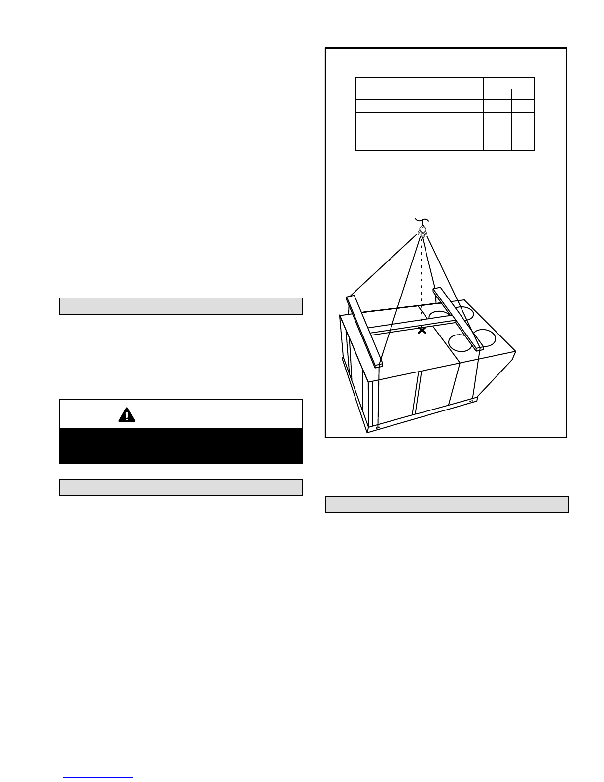
RIGGING
Unit
LG 156, LC 156, LC 180H
LG 180H, LC180U, LG 210
LC 210, LC 240, LC 300
LG 180U, LG 240, LG 300
*Maximum weight with all available factoryinstalled accessories.
LIFTING POINT SHOULD BE DIRECTLY
ABOVE CENTER OF GRAVITY
IMPORTANT - ALL PANELS MUST
BE IN PLACE FOR RIGGING.
*Weight
Lbs.
2855 1295
3000 1361
CAUTION - Do not
FIGURE 2
Kg.
10662350
walk on unit.
Rigging Unit For Lifting
Rig unit for lifting by attaching four cables to holes in unit
base rail. See figure 2.
1- Detach wooden base protection before rigging.
2- Connect rigging to the unit base using both holes in
each corner.
3- All panels must be in place for rigging.
4- Place field‐provided H‐style pick in place just above
top edge of unit. Frame must be of adequate
strength and length. (H-style pick prevents damage
to unit.)
LGH/LCH156, 180, 210, 240, 300S
Condensate Drains
Remove cap and make drain connection to the 1”
N.P.T. drain coupling provided on unit. A trap must be
installed between drain connection and an open vent
for proper condensate removal. See figure 3. It is
sometimes acceptable to drain condensate onto the
roof or grade; however, a tee should be fitted to the trap
to direct condensate downward. The condensate line
must be vented. Check local codes concerning
condensate disposal. Refer to pages 2, 3 and 4 for
condensate drain location.
Note - The drain pan is made with a glass reinforced
engineered plastic capable of withstanding typical joint
torque but can be damaged with excessive force. Tighten
pipe nipple hand tight and turn an additional quarter turn.
Page 8
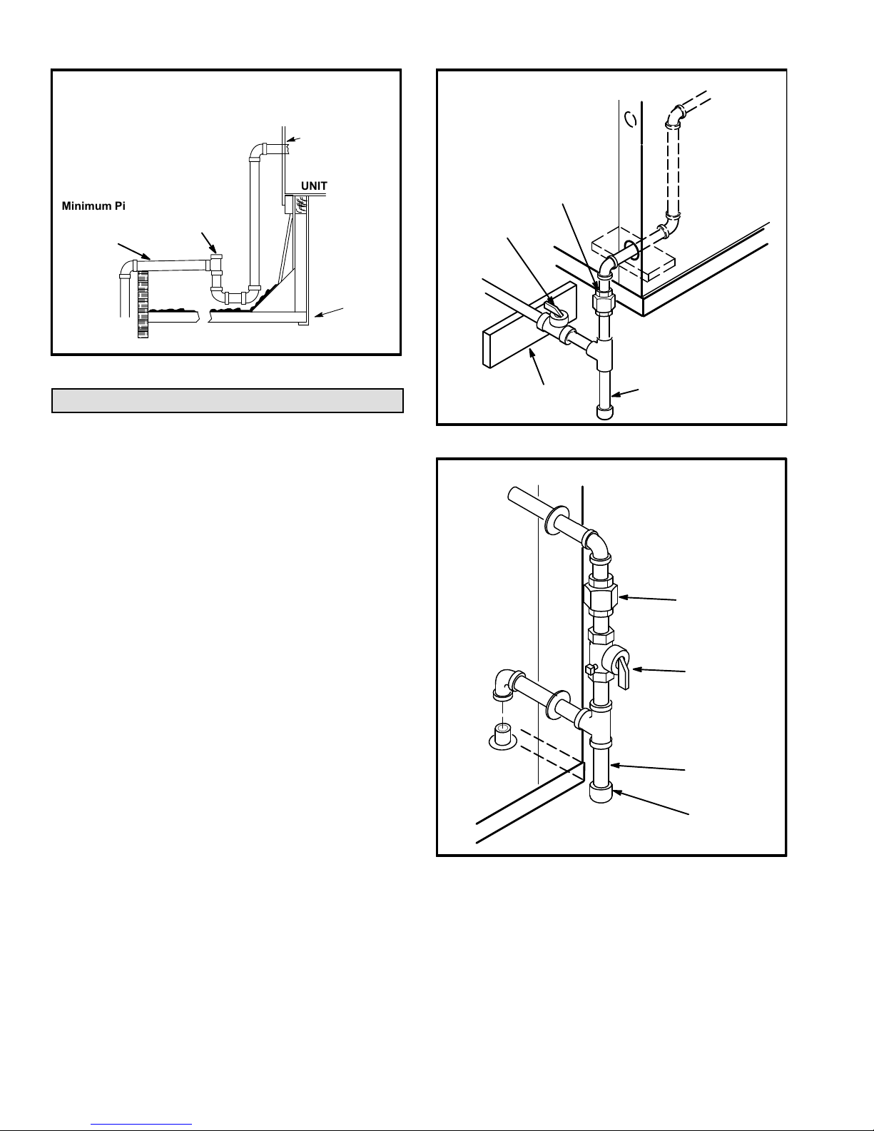
CONDENSATE DRAIN CONNECTION
OUTSIDE OF UNIT GAS PIPING
TO GAS
VALV E
NOTE - Allow clearance to
open doors when installing
condensate piping.
Minimum Pitch
1” (25 mm) per
10' (3 m) of line
OPEN VENT
CAULK AROUND
CONDENSATE
COUPLING
UNIT
MOUNTING
FRAME
FIGURE 3
Connect Gas Piping
Before connecting piping, check with gas company or
authorities having jurisdiction for local code
requirements. When installing gas supply piping, length
of run from gas meter must be considered in determining
pipe size for 0.5” w.c. (.12kPa) maximum pressure drop.
Do not use supply pipe smaller than unit gas connection.
For natural gas units, operating pressure at the unit gas
connection must be a minimum of 4.7” w.c. (1.17kPa)
and a maximum of 10.5” (2.60kPa) w.c. For LP/propane
gas units, operating pressure at the unit gas connection
must be a minimum of 11” w.c. (2.74kPa) and a maximum
of 13.5” w.c. (3.36kPa).
When making piping connections a drip leg should be
installed on vertical pipe runs to serve as a trap for
sediment or condensate. A 1/8” N.P.T. plugged tap is
located on gas valve for test gauge connection. Refer to
Heating Start-Up section for tap location. Install a ground
joint union between the gas control manifold and the
main manual shut-off valve. See figure 4 for gas supply
piping entering outside the unit. See figure 5 for gas
supply entering through bottom of unit.
Compounds used on threaded joints of gas piping shall be
resistant to the action of liquified petroleum gases.
MANUAL MAIN
SHUT-OFF VALVE
TO
GAS
SUPPLY
(REFER TO
LOCAL CODES)
BOTTOM ENTRY GAS PIPING
TO GAS
VALV E
EXISTING
SUPPLY
GROUND
JOINT UNION
GAS PIPING
SUPPORT
FIGURE 5
DRIP LEG
FIGURE 4
GROUND
JOINT UNION
MANUAL MAIN
SHUT-OFF VALVE
DRIP LEG
CAP
Page 9
507124-04 3/2016
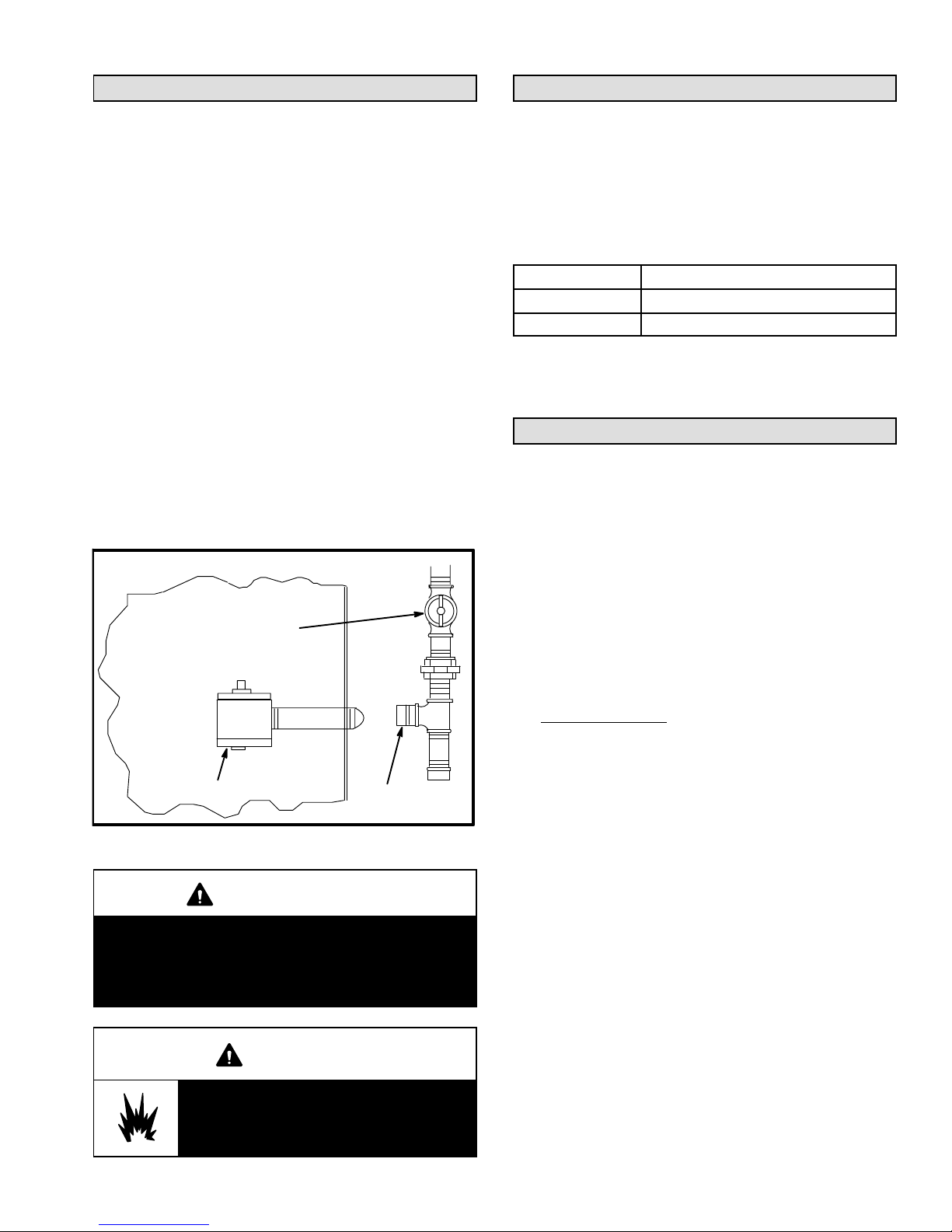
Pressure Test Gas Piping
High Altitude Derate
When pressure testing gas lines, the gas valve must
be disconnected and isolated. Gas valves can be
damaged if subjected to more than 0.5 psig (3.48kPa).
See figure 6.
NOTE-Codes may require that manual main shut-off
valve and union (furnished by installer) be installed in
gas line external to unit. Union must be of the ground
joint type.
After all connections have been made, check all piping
connections for gas leaks. Also check existing unit gas
connections up to the gas valve; loosening may occur
during installation. Use a leak detection solution or other
preferred means. Do not use matches candles or other
sources of ignition to check for gas leaks.
NOTE-In case emergency shut down is required, turn off
the main manual shut-off valve and disconnect main
power to unit. These devices should be properly labeled
by the installer.
PRESSURE TEST GAS LINE
MANUAL MAIN
SHUT-OFF VALVE
Locate the high altitude conversion sticker in the unit
literature bag. Fill out the conversion sticker and affix next
to the unit nameplate.
Refer to table 1 for high altitude adjustments.
TABLE 1
HIGH ALTITUDE DERATE
Altitude Ft.* Gas Manifold Pressure
2000-4500 See Unit Nameplate
4500 And Above Derate 2% / 1000 Ft. Above Sea Level
*Units installed at 0-2000 feet do not need to be modified.
NOTE ‐ This is the only permissible derate for these units.
Electrical Connections
POWER SUPPLY
Route field wiring in conduit between bottom power entry
disconnect. See figure 7. This does not supersede local
codes or authorities having jurisdiction.
Do not apply power or close disconnect switch until
installation is complete. Refer to start-up directions.
Refer closely to unit wiring diagram.
Refer to unit nameplate for minimum circuit ampacity
and maximum fuse size.
GAS VALVE
FIGURE 6
CAP
CAUTION
Some soaps used for leak detection are corrosive
to certain metals. Carefully rinse piping thoroughly
after leak test has been completed. Do not use
matches, candles, flame or othe sources of ignition
to check for gas leaks.
WARNING
Danger of explosion. Can cause injury
or product or property damage. Do not
use matches, candles, flame or other
sources of ignition to check for leaks.
LGH/LCH156, 180, 210, 240, 300S
Page 10
1- Units are factory-wired for 240/460/575 volt supply.
For 208V supply,
cover from the 208V terminal on the control
transformer. Move the wire from the transformer
240V terminal to the 208V terminal. Place the
insulated terminal cover on the unused 240V
terminal.
2- Route power through the bottom power entry area
and connect to line side of unit disconnect, circuit
breaker or terminal block. See unit wiring diagram.
3- Units With Optional 120v GFCI Outlet -
Route and connect separate 120v wiring to GFCI
outlets which do not have factory-installed wiring.
Route field wiring in conduit between bottom power
entry and GFCI. See figure 7.
4- Solar-Ready Units Only -
All solar-ready units are equipped with an S48
disconnect along with F54 and F56 fuse blocks
(located in the controls/compressor compartment).
Connect solar panel array wiring to the top of F54 and
F56 (one fuse block per solar array). Solar equipment
must be specified for use with this unit.
remove the insulated terminal
FIELD WIRE ROUTING
SIDE ENTRY
KNOCKOUTS
SEAL
WATERTIGHT
BOTTOM
POWER ENTRY
OPTIONAL
120V GFI
MAKE-
UP BOX
RUN FIELD
WIRING IN
FIELD PRO
VIDED CONDUIT
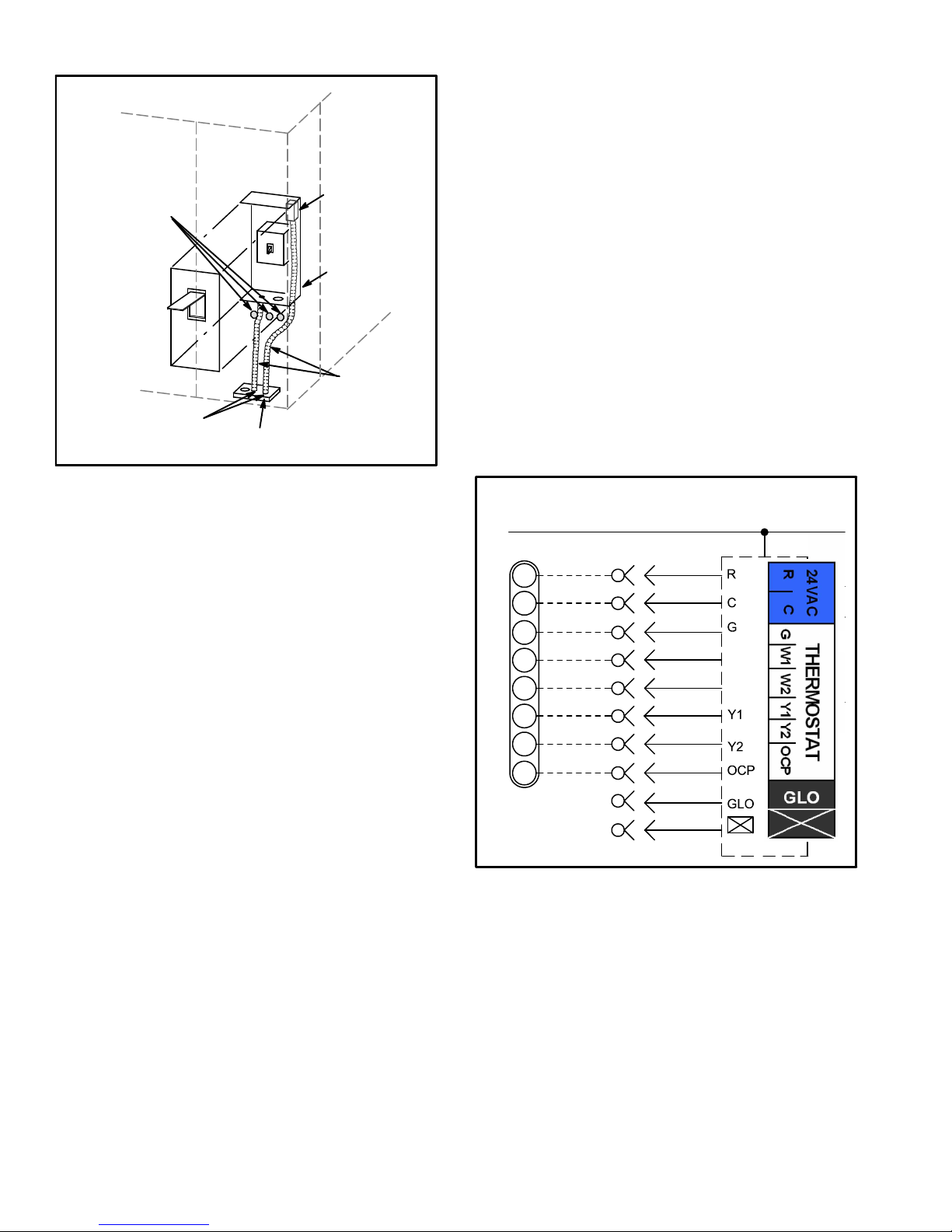
C-Wire Connections
The Unit Controller will operate the unit from a
thermostat or zone sensor based on the System Mode.
The default System Mode is the thermostat mode. Refer
to the Unit Controller Installation and Setup Guide to
change the System Mode. Use the menu navigation
arrows and select button; see SETTINGS > CONTROL.
1- Default Thermostat Mode -
The Unit Controller will operate two stages of heating
and cooling based on thermostat demands. Install
thermostat assembly in accordance with instructions
provided with thermostat. See figure 8 for field wiring
and and refer to wiring diagrams on unit.
IMPORTANT-Terminal connections at the wall plate or
subbase must be made securely. Loose control wire
connections may result in intermittent operation.
FIGURE 7
CONTROL WIRING
A-Thermostat Location
Room thermostat mounts vertically on a standard 2” X 4”
handy box or on any non-conductive flat surface.
Locate thermostat approximately 5 feet (1524mm)
above the floor in an area with good air circulation at
average temperature. Avoid locating the room
thermostat where it might be affected by:
-drafts or dead spots behind doors and in corners
-hot or cold air from ducts
-radiant heat from sun or appliances
-concealed pipes and chimneys
B-Wire Routing
Route thermostat cable or wires from subbase through
knockout provided in unit. Use 18 AWG wire for all
applications using remotely installed electro-mechanical
and electronic thermostats.
On hot gas reheat units, route wires from RH sensor or
remote switch through knockout provided in unit. For
sensor installations, use 22AWG stranded, two twisted
pairs, individually shielded, 100% aluminum shield with
drain wire and Teflon jacket.
IMPORTANT - Unless field thermostat wires are rated for
maximum unit voltage, they must be routed away from
line voltage wiring.
FIELD WIRING WITH ELECTRONIC AND
ELECTRO-MECHANICAL THERMOSTATS
(Thermostat Mode)
24 V POWER
J297A
R
C
G
W1
W2
Y1
Y2
OCP
P297
1
2
B
3
4
5
6
7
8
C
9
10
A55
W1
W2
FIGURE 8
2- Zone Sensor Mode -
The Unit Controller will operate heating and cooling
based on the Unit Controller internal setpoints and the
temperature from the A2 zone sensor. An optional
Network Control Panel (NCP) can also be used to provide
setpoints. A thermostat or return air sensor can be used
as a back-up mode. Make zone sensor wiring
connections as shown in figure 9.
Note - Install sensor and make communication wiring
connections as shown in literature provided with sensor.
Page 11
507124-04 3/2016
P262
10
11
12
J262C
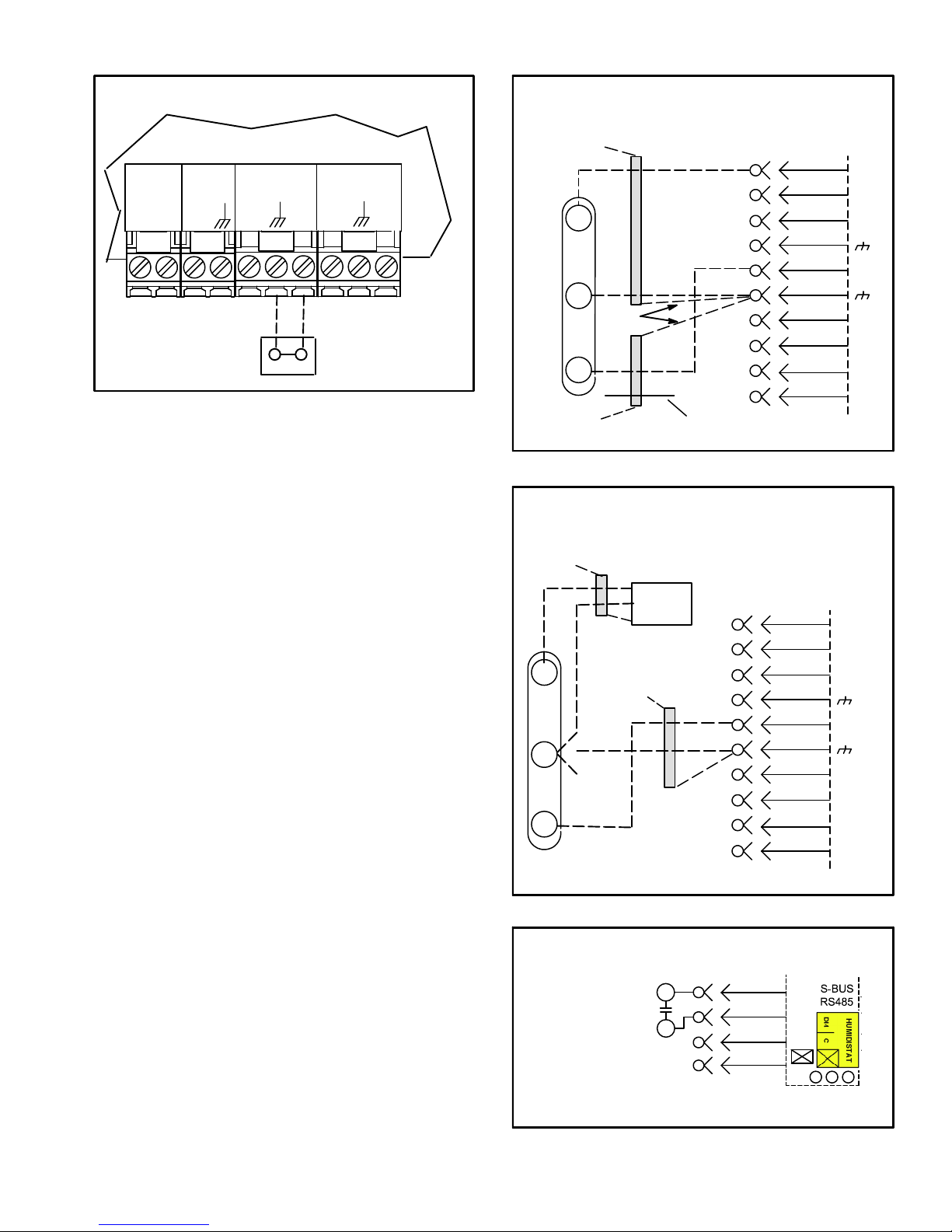
FIELD WIRING IN ZONE SENSOR MODE
(Zone Sensor Mode)
UNIT CONTROLLER
24VAC
RC
SENSOR
IAQ
AI1
SENSOR
HUM
A2 SENSOR
TMP
OUTPUTS
D01
D02
J298
FIGURE 9
D-Hot Gas Reheat Units Only
1- Install humidity sensor in accordance with instructions
provided with sensor. A DDC input may be used to
initiate dehumidification instead of a sensor.
2- Make wiring connections as shown in figure 8 for
Thermostat Mode and figure 9 for Zone Sensor
Mode. In addition, connect either a humidity sensor
or a dehumidification input. See figure 10 or 11 for
humidity sensor wiring and figure 12 for
dehumidification input wiring.
Humidity Sensor Cable Applications:
Wire runs of 50 feet (mm) or less:
Use two separate shielded cables containing 20AWG
minimum, twisted pair conductors with overall shield.
Belden type 8762 or 88760 (plenum) or equivalent.
Connect both cable shield drain wires to TB1-7 as shown
in figure 10.
Wire runs of 150 feet (mm) or less:
Use two separate shielded cables containing 18AWG
minimum, twisted pair conductors with overall shield.
Belden type 8760 or 88760 (plenum) or equivalent.
Connect both cable shield drain wires to TB1-7 as shown
in figure 10.
Wire runs over 150 feet (mm):
Use a local, isolated 24VAC transformer such as Lennox
cat #18M13 (20VA minimum) to supply power to RH
sensor as shown in figure 11. Use two shielded cables
containing 20AWG minimum, twisted pair conductors
with overall shield. Belden type 8762 or 88760 (plenum)
or equivalent.
Page 12
LGH/LCH156, 180, 210, 240, 300S
FIELD WIRING REHEAT UNITS (Using A Humidity
Sensor With Less Than 150 Ft. Wire Runs)
NOT
CONNECTED
A91
VIN
GND
VO
NOT
CONNECTED
DRAIN
J298A
UNUSED
WIRE
1
2
B
3
4
C
5
6
7
D
8
9
10
A55 UNIT
CONTROLLER
P298
FIGURE 10
FIELD WIRING REHEAT UNITS (Using A Humid
ity Sensor With More than 150 Ft. Wire Runs)
NOT
CONNECTED
A91
VIN
GND
ISOLATED 24V
TRANSFORMER
DRAIN
NOT
CONNECTED
J298A
A55 UNIT
CONTROLLER
P298
1
2
B
3
4
C
5
R
C
AI-1
HUM
6
7
TMP
D
VO
8
9
10
DO-1
C
DO-2
DI-1
FIGURE 11
FIELD WIRING REHEAT UNITS
(Using A Dehumidification Switch)
J299
R
DI−4
C
DEHUMIDIFICATION
SWITCH
Use 24 VAC (R) from any terminal
available on J299−2, −5, or −7.
7
8
9
10
FIGURE 12
R
C
AI-1
HUM
TMP
DO-1
C
DO-2
DI-1
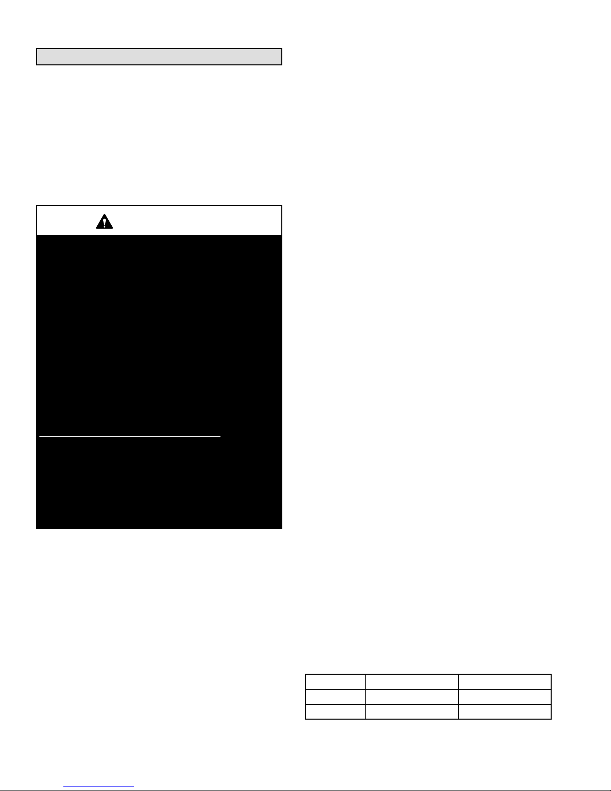
Blower Operation and Adjustments
B-Blower Access
Supply Air Inverter Units - The blower rotation will
always be correct on units equipped with an inverter.
Checking blower rotation is not a valid method of
determining voltage phasing for incoming power.
Supply Air Inverter Units and Units Equipped With
Optional Voltage or Phase Detection - The Unit
Controller checks the incoming power during start-up. If
the voltage or phase is incorrect, the Unit Controller will
display an alarm and the unit will not start.
IMPORTANT
Three Phase Scroll Compressor Voltage Phasing
Three phase scroll compressors must be phased se
quentially to ensure correct compressor and blower*
rotation and operation. Compressor and blower are
wired in phase at the factory. Power wires are colorcoded as follows: line 1-red, line 2-yellow, line 3-blue.
1-Observe suction and discharge pressures and blow
er* rotation on unit start-up.
2-Suction pressure must drop, discharge pressure must
rise and blower* rotation must match rotation marking.
If pressure differential is not observed or blower* rota
tion is not correct:
3-Disconnect all remote electrical power supplies.
4-Reverse any two field-installed wires connected to
the line side of S48 disconnect or TB13 terminal strip.
Do not reverse wires at blower contactor.
5-Make sure the connections are tight.
Discharge and suction pressures should operate at
their normal start‐up ranges.
*Supply air inverter blower motors should rotate in the
correct direction; verify scroll compressor rotation
separately. Contact technical support if the blower is
rotating incorrectly.
1- Disconnect jack/plug connector to blower motor. Also
disconnect jack/plug connector heating limit switches
on gas units.
2- Remove screws on either side of blower assembly
sliding base. See figure 13.
3- Pull base toward outside of unit.
C-Determining Unit CFM
IMPORTANT - Supply air inverter units are factory-set
to run the blower at full speed when there is a blower (G)
demand without a heating or cooling demand. Refer to
the field-provided, design specified CFM for all modes
of operation. Use the following procedure to adjust
motor pulley to deliver the highest CFM called for in the
design spec. See Inverter Start-Up section to set blower
CFM for all modes once the motor pulley is set.
1- The following measurements must be made with a
dry indoor coil. Run blower (G demand) without a
cooling demand. Measure the indoor blower shaft
RPM. Air filters must be in place when measurements
are taken.
2- With all access panels in place, measure static
pressure external to unit (from supply to return).
Blower performance data is based on static pressure
readings taken in locations shown in figure 14.
Note - Static pressure readings can vary if not taken
where shown.
3- Referring to page 17, use static pressure and RPM
readings to determine unit CFM. Use page 18 when
installing units with any of the optional accessories
listed.
A-Blower Operation
Initiate blower only (G) demand at thermostat according
to instructions provided with thermostat. Unit will cycle on
thermostat demand. The following steps apply to
applications using a typical electro-mechanical
thermostat.
1- Blower operation is manually set at the thermostat
subbase fan switch. With fan switch in ON position,
blowers will operate continuously.
2- With fan switch in AUTO position, the blowers will
cycle with demand. Blowers and entire unit will be off
when system switch is in OFF position.
4- The blower RPM can be adjusted at the motor pulley.
Loosen Allen screw and turn adjustable pulley
clockwise to increase CFM. Turn counterclockwise to
decrease CFM. See figure 13. Do not exceed
minimum and maximum number of pulley turns as
shown in table 2.
TABLE 2
MINIMUM AND MAXIMUM PULLEY ADJUSTMENT
Belt Minimum Turns Open Maximum Turns Open
A Section No minimum 5
B Section 1* 6
*No minimum number of turns open when B belt is used on
pulleys 6” O.D. or larger.
Page 13
507124-04 3/2016
TO INCREASE CFM
LOOSEN ALLEN SCREW &
TURN PULLEY CLOCKWISE
TO DECREASE CFM
TURN PULLEY
COUNTERCLOCKWISE
BLOWER
ASSEMBLY
SLIDING BASE
LOOSEN (4) SCREWS TO
ADJUST BELT TENSION
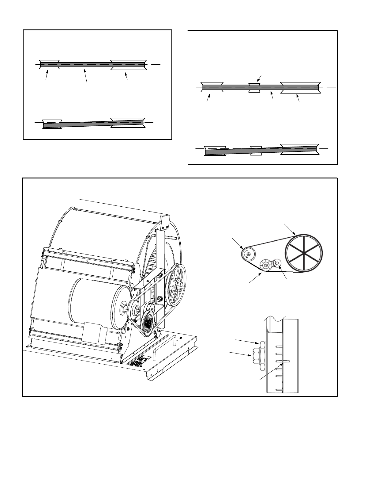
BLOWER ASSEMBLY - NO TENSIONER
TO INCREASE BELT TENSION
1-Loosen four screws securing blower motor to
2-Turn adjusting screw to the left, or counter
3-Tighten four screws.
BELT TENSION
ADJUSTING
SCREW
BLOWER
MOTOR
sliding base.
clockwise, to move the motor downward and
tighten the belt.
BLOWER
WHEEL
SIDE VIEW
MOTOR
ALLEN
SCREW
PULLEY
INSTALLATIONS WITH DUCTWORK
ROOFTOP UNIT
READING LOCATION
SUPPLY
MAIN
RE
TURN
FIRST BRANCH
OFF OF MAIN RUN
DUCT RUN
PULLEY
REMOVE SCREWS TO
SLIDE BLOWER
ASSEMBLY OUT OF UNIT
FIGURE 13
LOCATION OF STATIC PRESSURE READINGS
INSTALLATIONS WITH CEILING DIFFUSERS
ROOFTOP UNIT
RETURN AIR
SUPPLY
SUPPLY AIR
READING
LOCATION
SUPPLY AIR
READING
LOCATION
DIFFUSER
RE
TURN
RETURN AIR
READING
LOCATION
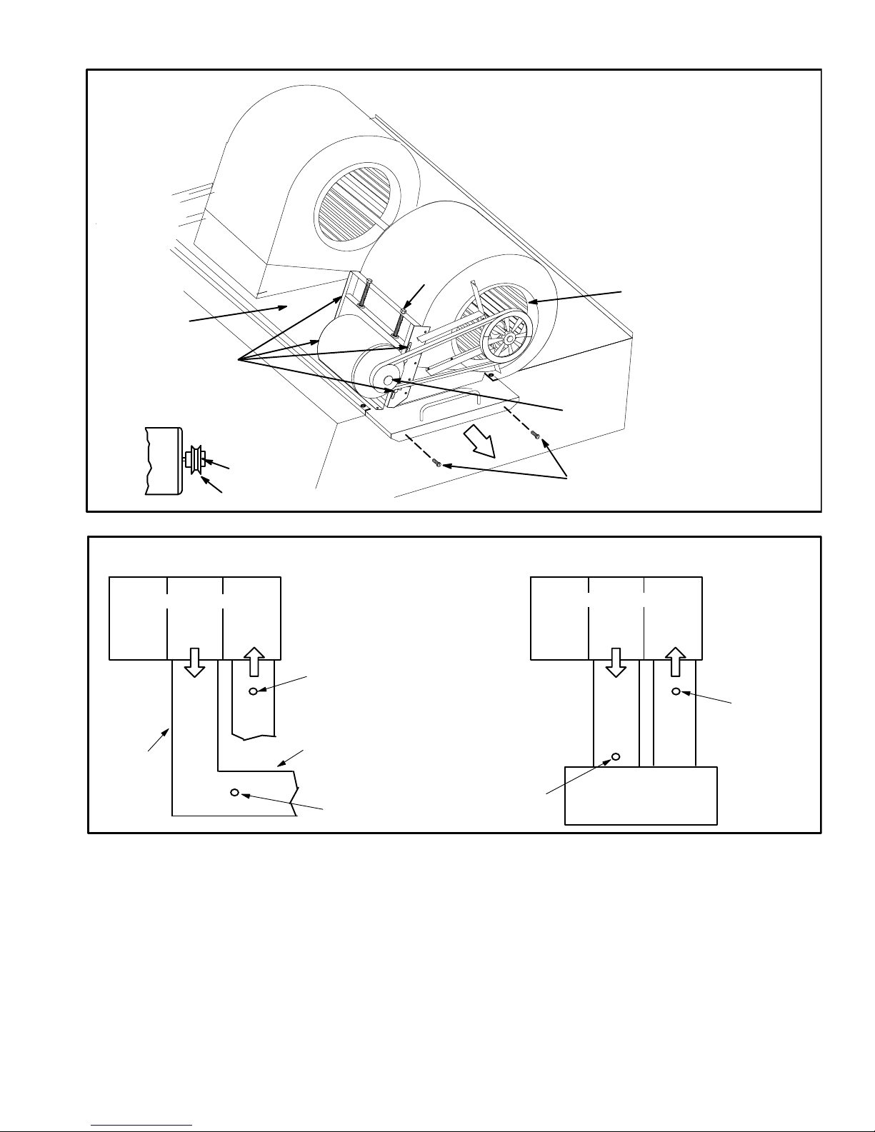
D-Blower Belt Adjustment
Maximum life and wear can be obtained from belts only if
proper pulley alignment and belt tension are maintained.
Tension new belts after a 24-48 hour period of operation.
This will allow belt to stretch and seat into pulley grooves.
Make sure blower and motor pulley are aligned. See figure
15 for blowers not equipped with a tensioner and figure 16
for units equipped with an optional belt tensioner.
Blowers Without Belt Tensioner
1- Loosen four screws securing blower motor to sliding
base. See figure 13.
LGH/LCH156, 180, 210, 240, 300S
FIGURE 14
2- To increase belt tension -
Turn belt tension adjusting screw to the left, or
counterclockwise, to tighten the belt. This increases
the distance between the blower motor and the
blower housing.
To loosen belt tension -
Turn the adjusting screw to the right, or clockwise to
loosen belt tension.
3- Tighten four screws securing blower motor to sliding
base once adjustments have been made.
Page 14
PULLEY ALIGNMENT - NO TENSIONER
PULLEY ALIGNMENT - WITH TENSIONER
MOTOR
PULLEY
ALIGNED
BELT
NOT ALIGNED
FIGURE 15
BLOWER
PULLEY
MOTOR
PULLEY
PULLEY ALIGNMENT - WITH TENSIONER
ADJUSTABLE
PULLEY
ALIGNED
TENSIONER
BELT
BLOWER
PULLEY
NOT ALIGNED
FIGURE 16
FIXED
PULLEY
FIGURE 17
NUT
BOLT
TENSIONER
ALIGN
TENSIONER
MARKS
TENSIONER BOLT AND
ADJUSTMENT NUT
Page 15
507124-04 3/2016
Blowers Equipped With Belt Tensioner
1- Loosen the bolt in the center of the tensioner. See
figure 17.
2- Place belt over all three pulleys.
3- Using a 15/16” wrench, turn the tensioner nut until
marks align as shown in figure 17.
4- Hold the tensioner with marks aligned and tighten the
bolt to 23 ft.lbs. using the 9/16” wrench.
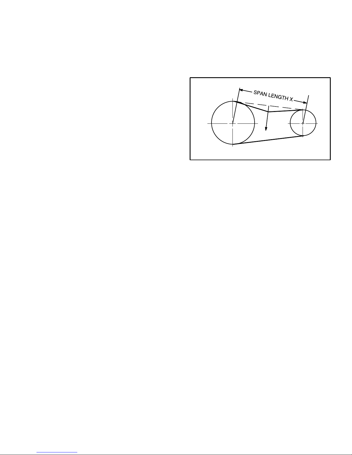
E-Check Belt Tension
Overtensioning belts shortens belt and bearing life.
Check belt tension as follows:
1- Measure span length X. See figure 18.
3- Measure belt deflection force. For a used belt, the
deflection force should be 5 lbs. (35kPa) . A new belt
deflection force should be 7 lbs. (48kPa).
A force below these values indicates and
undertensioned belt. A force above these values
indicates an overtensioned belt.
MEASURE BELT TENSION
FORCE
2- Apply perpendicular force to center of span (X) with
enough pressure to deflect belt 1/64” for every inch
of span length or 1.5mm per 100mm of span length.
Example: Deflection distance of a 40” span would be
40/64” or 5/8”.
Example: Deflection distance of a 400mm span
would be 6mm.
DEFLECTION 1/64” PER INCH OF SPAN
OR 1.5mm PER 100mm OF SPAN
FIGURE 18
F-Field-Furnished Blower Drives
For field-furnished blower drives, use page 17 or 18 to
determine BHP and RPM required. Reference table 3 to
determine the manufacturer's model number.
LGH/LCH156, 180, 210, 240, 300S
Page 16

TOTAL STATIC PRESSURE - Inches Water Gauge (Pa)
5 4.95 1160 5.35 1205 5.80 1250 6.25
100 8.25 1150 8.95 1195 9.60 1240 10.30 1285 11.05 - - - - - - - - - - - -
0.20 0.40 0.60 0.80 1.00 1.20 1.40 1.60 1.80 2.00 2.20 2.40 2.60
RPM BHP RPM BHP RPM BHP RPM BHP RPM BHP RPM BHP RPM BHP RPM BHP RPM BHP RPM BHP RPM BHP RPM BHP RPM BHP
Air
1 - Wet indoor coil air resistance of selected unit.
2 - Any factory installed options air resistance (electric heat, economizer, etc.)
BLOWER DATA
BLOWER TABLE INCLUDES RESISTANCE FOR BASE UNIT ONLY WITH DRY INDOOR COIL & AIR FILTERS IN PLACE
FOR ALL UNITS ADD:
3 - Any eld installed accessories air resistance (electric heat, duct resistance, diffuser, etc.)
Then determine from blower table blower motor output and drive required.
See page 18 for wet coil and option/accessory air resistance data.
See page 18 for factory installed drive kit specications.
MINIMUM AIR VOLUME REQUIRED FOR DIFFERENT GAS HEAT SIZES
Low (L), Standard (S) and Medium Heat (M) - 4500 cfm minimum
High Heat (H) - 5125 cfm minimum
cfm
Volume
2750 385 0.30 505 0.50 600 0.70 680 0.90 755 1.10 820 1.30 - - - - - - - - - - - - - - - - - - - - - - - - - - - - - - - - - - - - - - - - - -
3000 395 0.35 515 0.55 610 0.75 685 1.00 760 1.20 825 1.45 885 1.70 - - - - - - - - - - - - - - - - - - - - - - - - - - - - - - - - - - - -
3250 405 0.40 520 0.60 615 0.85 695 1.10 765 1.30 830 1.60 890 1.85 950 2.10 - - - - - - - - - - - - - - - - - - - - - - - - - - - - - -
3500 415 0.45 530 0.70 620 0.95 700 1.20 775 1.45 840 1.70 900 2.00 955 2.25 1005 2.55 - - - - - - - - - - - - - - - - - - - - - - - -
3750 425 0.50 540 0.75 630 1.05 710 1.30 780 1.60 845 1.85 905 2.15 960 2.45 1010 2.70 1060 3.00 1110 3.30 - - - - - - - - - - - -
4000 435 0.55 545 0.85 635 1.10 715 1.40 785 1.70 850 2.00 910 2.30 965 2.60 1020 2.90 1070 3.25 1115 3.55 1160 3.85 1205 4.15
4250 445 0.60 555 0.90 645 1.25 725 1.55 795 1.85 855 2.15 915 2.45 970 2.80 1025 3.10 1075 3.45 1120 3.75 1165 4.10 1210 4.45
4500 455 0.70 565 1.00 655 1.35 730 1.65 800 2.00 865 2.35 925 2.65 980 3.00 1030 3.30 1080 3.65 1130 4.05 1175 4.35 1215 4.70
4750 470 0.75 575 1.10 660 1.45 740 1.80 810 2.15 870 2.50 930 2.85 985 3.20 1040 3.55 1085 3.90 1135 4.25 1180 4.65 1225 5.00
Page 17
5000 480 0.85 585 1.25 670 1.60 750 1.95 815 2.30 880 2.70 940 3.05 995 3.40 1045 3.80 1095 4.15 1140 4.50 1185 4.90 1230 5.30
5250 495 0.95 595 1.35 680 1.70 755 2.10 825 2.50 890 2.90 945 3.25 1000 3.65 1050 4.00 1100 4.40 1150 4.80 1195 5.20 1235 5.60
5500 505 1.05 605 1.45 690 1.85 765 2.25 835 2.65 895 3.05 955 3.45 1010 3.85 1060 4.25 1110 4.70 1155 5.10 1200 5.50 1240 5.90
5750 520 1.15 615 1.60 700 2.00 775 2.45 840 2.85 905 3.25 960 3.65 1015 4.10 1065 4.50 111
6000 530 1.30 630 1.75 710 2.15 785 2.60 850 3.05 910 3.45 970 3.90 1025 4.35 1075 4.80 1120 5.20 1170 5.65 1215 6.10 1255 6.55
6250 545 1.40 640 1.90 720 2.35 795 2.80 860 3.25 920 3.70 975 4.15 1030 4.60 1080 5.05 1130 5.50 1175 5.95 1220 6.45 1265 6.90
6500 560 1.55 650 2.05 730 2.50 805 3.00 870 3.45 930 3.95 985 4.40 1040 4.85 1090 5.35 1140 5.85 1185 6.30 1225 6.75 1270 7.25
6750 570 1.70 665 2.20 745 2.70 815 3.20 880 3.70 940 4.20 995 4.65 1045 5.10 1095 5.60 1145 6.10 1190 6.60 1235 7.10 1275 7.60
7000 585 1.85 675 2.35 755 2.90 825 3.40 890 3.95 950 4.45 1005 4.95 1055 5.40 1105 5.95 1155 6.45 1200 6.95 1240 7.45 1285 8.00
7250 600 2.00 690 2.60 765 3.10 835 3.65 900 4.15 955 4.65 1015 5.25 1065 5.75 1115 6.25 1160 6.75 1205 7.30 1250 7.85 1290 8.35
7500 615 2.20 700 2.75 775 3.30 845 3.85 910 4.45 965 4.95 1020 5.50 1075 6.05 1125 6.60 1170 7.15 1215 7.65 1260 8.25 1300 8.75
7750 630 2.40 715 3.00 790 3.55 855 4.10 920 4.70 975 5.25 1030 5.80 1080 6.35 1130 6.90 1180 7.50 1225 8.05 1265 8.60 1305 9.15
8000 640 2.55 725 3.20 800 3.80 865 4.35 930 4.95 985 5.50 1040 6.10 1090 6.70 1140 7.25 1185 7.85 1230 8.40 1275 9.00 1315 9.60
8250 655 2.80 740 3.40 810 4.00 880 4.65 940 5.25 995 5.85 1050 6.45 1100 7.05 1150 7.65 1195 8.25 1240 8.85 1280 9.40 1325 10.05
8500 670 3.00 750 3.65 825 4.30 890 4.90 950 5.55 1005 6.15 1060 6.80 1110 7.40 1160 8.05 1205 8.65 1250 9.25 1290 9.85 1330 10.45
8750 685 3.25 765 3.90 835 4.55 900 5.20 960 5.85 1015 6.45 1070 7.15 1120 7.75 1165 8.35 1215 9.05 1255 9.65 1300 10.30 1340 10.90
9000 700 3.50 780 4.20 850 4.85 910 5.50 970 6.15 1025 6.80 1080 7.50 1130 8.15 1175 8.75 1220 9.40 1265 10.10 1310 10.80 1350 11.40
9250 715 3.75 790 4.45 860 5.15 925 5.85 985 6.55 1040 7.20 1090 7.85 1140 8.55 1185 9.20 1230 9.85 1275 10.55 1315 11.20 - - - - - -
9750 745 4.30 820 5.05 885 5.75 950 6.55 1005 7.20 1060 7.95 1110 8.65 1160 9.40 1205 10.05 1250 10.80 1295 11.50 - - - - - - - - - - - -
9500 730 4.00 805 4.75 875 5.45 935 6.15 995 6.90 1050 7.60 1
10,000 760 4.60 835 5.40 900 6.15 960 6.85 1015 7.60 1070 8.35 1120 9.05 1170 9.80 1215 10.50 1260 11.25 - - - - - - - - - - - - - - - - - -
10,250 775 4.90 845 5.65 910 6.45 970 7.20 1030 8.00 1080 8.75 1135 9.55 1180 10.25 1225 11.00 - - - - - - - - - - - - - - - - - - - - - - - -
10,500 790 5.20 860 6.00 925 6.85 985 7.65 1040 8.40 1095 9.20 1145 10.00 1190 10.70 1235 11.45 - - - - - - - - - - - - - - - - - - - - - - - -
10,750 805 5.55 875 6.40 940 7.25 1000 8.05 1055 8.85 1105 9.65 1155 10.45 1200 11.20 - - - - - - - - - - - - - - - - - - - - - - - - - - - - - -
11,000 820 5.90 890 6.80 950 7.60 1010 8.45 1065 9.30 111 5 10.05 1165 10.90 - - - - - - - - - - - - - - - - - - - - - - - - - - - - - - - - - - - -
BLOWER DATA
FACTORY INSTALLED BELT DRIVE KIT SPECIFICATIONS
Motor Efciency Nominal hp Maximum hp Drive Kit Number RPM Range
Standard or High 2 2.30 1 535 - 725
Standard or High 2 2.30 2 710 - 965
Standard 3 3.45 1 535 - 725
Standard 3 3.45 2 710 - 965
High 3 3.45 3 685 - 856
High 3 3.45 4 850 - 1045
Standard 5 5.75 3 685 - 856
Standard 5 5.75 4 850 - 1045
Standard 5 5.75 5 945 - 1185
Standard 7.5 8.63 6 850 - 1045
Standard 7.5 8.63 7 945 - 1185
Standard 7.5 8.63 8 1045 - 1285
Standard 10 11.50 7 945 - 1185
Standard 10 11.50 10 1045 - 1285
Standard 10 11.50 11 1135 - 1365
NOTE - Using total air volume and system static pressure requirements determine from blower performance tables rpm and motor output required. Maximum usable
output of motors furnished are shown. In Canada, nominal motor output is also maximum usable motor output. If motors of comparable output are used, be sure to keep
within the service factor limitations outlined on the motor nameplate.
NOTE – Units equipped with an inverter are limited to a motor service factor of 1.0.
FACTORY INSTALLED OPTIONS/FIELD INSTALLED ACCESSORY AIR RESISTANCE
Horizontal
Roof Curb
156
thru
240
300S
Air
Vol-
ume
CFM
Wet Indoor Coil
156H,
180H
180U, 240U,
210H, 240H,
300S
Condenser
Reheat
Coil
Gas Heat Exchanger
Low/
Standard
Heat
Medium
Heat
High
Heat
Electric
Heat
Econo
mizer
Filters
in. w.g. in. w.g. in. w.g. in. w.g. in. w.g. in. w.g. in. w.g. in. w.g. MERV 8 MERV 13 in. w.g. in. w.g.
2750 .01 .02 .01 .02 .04 .05 - - - - - - .01 .03 - - - - - 3000 .01 .02 .01 .03 .04 .05 - - - - - - .01 .03 - - - - - 3250 .01 .03 .01 .03 .05 .06 - - - - - - .01 .04 .01 - - 3500 .01 .03 .02 .03 .05 .06 - - - - - - .01 .04 .01 - - 3750 .01 .03 .02 .04 .06 .07 - - - - - - .01 .04 .01 - - 4000 .02 .04 .02 .04 .06 .07 - - - - - - .04 .06 .06 - - 4250 .02 .04 .02 .04 .06 .08 - - - - - - .04 .06 .07 - - 4500 .02 .05 .02 .05 .07 .09 - - - - - - .04 .07 .07 .02
4750 .02 .05 .02 .05 .08 .10 - - - - - - .04 .07 .08 .03
5000 .02 .05 .02 .05 .09 .11 - - - - - - .05 .07 .08 .03
5250 .02 .06 .03 .06 .10 .12 - - - - - - .05 .07 .09 .04
5500 .02 .07 .03 .06 .10 .13 - - - - - - .05 .07 .10 .04
5750 .03 .07 .03 .06 .11 .14 - - - - - - .05 .08 . 11 .05
6000 .03 .08 .03 .07 .12 .15 .01 - - - .05 .08 .11 .06
6250 .03 .08 .03 .07 .12 .16 .01 .01 .05 .08 .12 .07
6500 .03 .09 .04 .08 .13 .17 .01 .02 .05 .08 .13 .08
6750 .04 .10 .04 .08 .14 .18 .01 .03 .05 .08 .14 .08
7000 .04 .10 .04 .09 .15 .19 .01 .04 .06 .08 .15 .09
7250 .04 .11 .04 .09 .16 .20 .01 .05 .06 .09 .16 .10
7500 .05 .12 .05 .10 .17 .21 .01 .06 .06 .09 .17 .11
8000 .05 .13 .05 .11 .19 .24 .02 .09 .06 .09 .19 .13
8500 .06 .15 .05 .12 .20 .26 .02 .11 .06 .09 .21 .15
9000 .07 .16 .06 .13 .23 .29 .04 .14 .07 .10 .24 .17
9500 .08 .18 .07 .14 .25 .32 .05 .16 .07 .10 .26 .19
10,000 .08 .20 .07 .16 .27 .35 .06 .19 .07 . 11 .29 .21
10,500 .09 .22 .08 .17 .30 .38 .09 .22 .07 . 11 .31 .24
11,000 . 11 .24 .08 .18 .31 .40
.11 .25 .08 .
11 .34 .27
Page 18
 Loading...