

Litho U.S.A.
2015
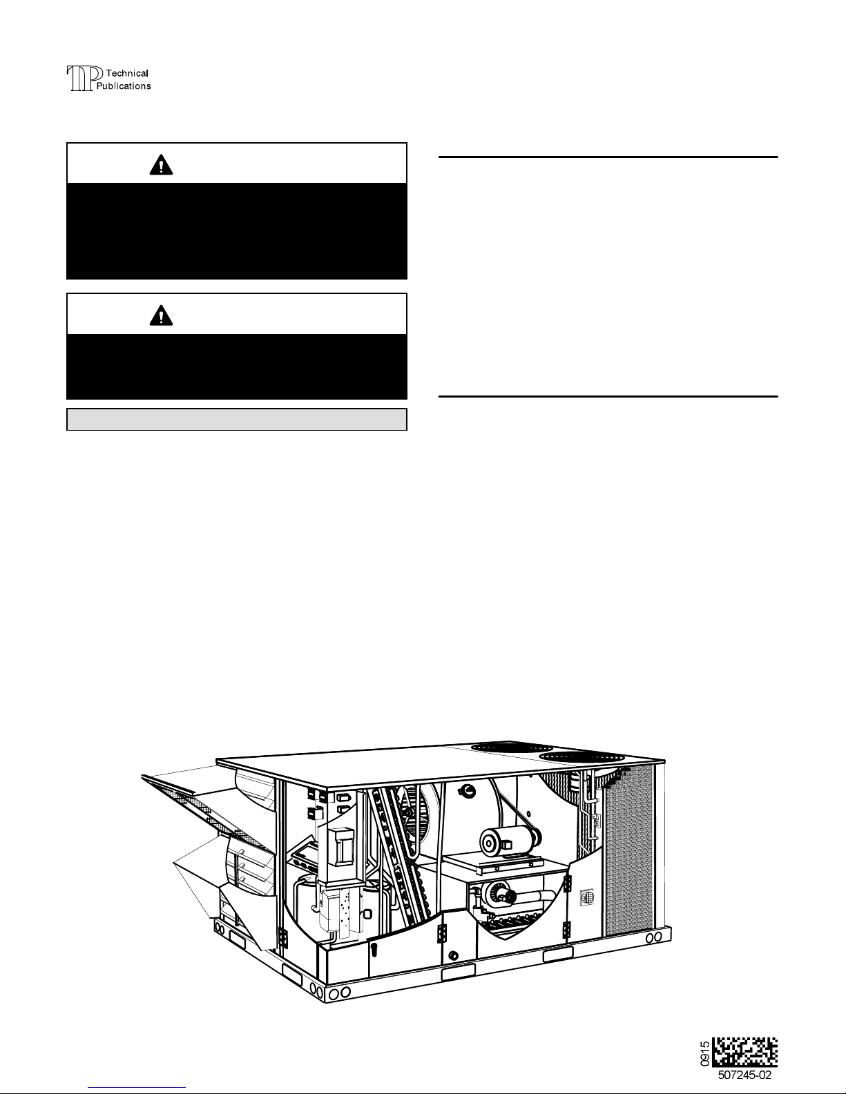
INSTALLATION
INSTRUCTIONS
WARNING
Improper installation, adjustment, alteration, ser
vice or maintenance can cause property damage,
personal injury or loss of life. Installation and ser
vice must be performed by a licensed professional
HVAC installer or equivalent, service agency, or the
gas supplier
CAUTION
Danger of sharp metallic edges. Can cause injury.
Take care and wear protective clothing when
servicing unit to avoid accidental contact with
sharp edges.
Table Of Contents
Dimensions Page 2.................................
Parts Arrangements Page 4.........................
Shipping and Packing List Page 5....................
General Page 5....................................
Safety Page 5.....................................
Unit Support Page 6................................
Duct Connection Page 7............................
Rigging Unit For Lifting Page 7.......................
Condensate Drains Page 7..........................
Gas Piping Page 9.................................
Pressure Test Gas Piping Page 10.....................
High Altitude Derate Page 11.........................
Electrical Connections Page 11.......................
Blower Operation and Adjustments Page 14............
LGH092H, LCH092H
LGH094U, LCH094U
LGH102H, LCH102H
LGH120H, LCH120H
LGH122U, LCH122U
LGH150S, LCH150S
LGH152U, LCH152U
PACKAGED UNITS
507245-02
9/2015
Supersedes 507245-01
Cooling Start-Up Page 22............................
Gas Heat Start-Up Page 34...........................
Heating Operation and Adjustments Page 35............
Electric Heat Start-Up Page 35........................
Supply Air Inverter Start-Up Page 36...................
Supply Air Inverter and Direct Drive Operation Page 38...
Direct Drive Start-Up Page 38.........................
Hot Gas Reheat Operation and Start-Up Page 40........
Service Page 41....................................
Unit Controller Parameter Settings Page 45.............
(7.5 Ton)
(7.5 Ton)
(8.5 Ton)
(10 Ton)
(10 Ton)
(12.5 Ton)
(12.5 Ton)
RETAIN THESE INSTRUCTIONS FOR FUTURE REFERENCE
3
3
LGH SHOWN
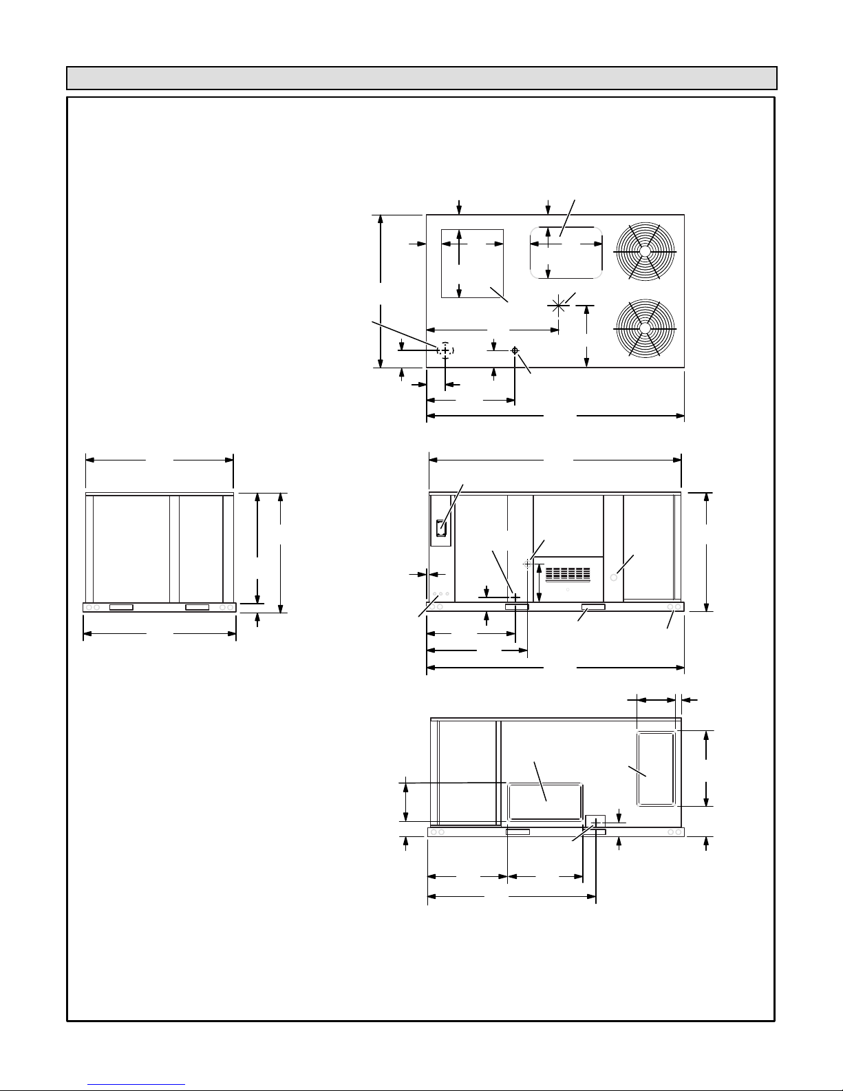
LGH/LCH092, 102, 120, & 150 DIMENSIONS - GAS HEAT SECTION SHOWN
58-1/8
(1476)
43-3/8
(1102)
46-7/8
(1191)
60-1/8 (1527)
BOTTOM
POWER ENTRY
5-1/2 (140) Dia.
BASE
AA
6-1/8
(156)
7 (178)
1
(25)
6-1/8
(156)
(610)
27
(686)
BOTTOM RETURN
6-5/8
(168)
DD
7 (178)
34-7/8
(886)
OPTIONAL DISCONNECT
(FACTORY INSTALLED)
CONDENSATE
DRAIN (FRONT)
24
10-3/4
(273)
AIR OPENING
EE
5-3/8
(137)
5-5/8
(143)
28
(711)
20
(508)
BOTTOM
CONDENSATE
101-1/4
(2572)
TOP VIEW
99-1/4
(2521)
GAS SUPPLY
INLET
18-1/2
(470)
BOTTOM SUPPLY
AIR OPENING
CENTER OF
GRAVITY
FF
BASE
OUTLET
FLUE
BB
CC
46-7/8
(1191)
60-1/8
(1527)
END VIEW
3-1/2
(89)
ELECTRIC
INLETS
15-1/2
(394)
6-1/8
(156)
34-7/8
(886)
31-1/2
(800)
FORKLIFT SLOTS
39-7/8
(1013)
(BOTH SIDES)
101-1/4
(2572)
SIDE VIEW
HORIZONTAL
SUPPLY AIR
OPENING
CONDENSATE
DRAIN (BACK)
30
66-3/8
(1686)
(762)
SIDE VIEW
(Horizontal Openings)
LIFTING HOLES
(FOR RIGGING)
15-1/2
(394)
HORIZONTAL
RETURN AIR
OPENING
5-3/8
(137)
1-5/8
(41)
30
(762)
12-1/8
(308)
Page 2

LGH/LCH094, 122, & 152 DIMENSIONS - GAS HEAT SECTION SHOWN
58-1/8
(1476)
43-3/8
(1102)
BOTTOM
POWER ENTRY
5-1/2 (140)
Diameter
46-7/8
(1191)
6-1/8
(156)
60-1/8 (1527)
BASE
7 (178)
6-1/8
(156)
AA
24
(610)
27
(686)
BOTTOM RETURN
AIR OPENING
6-5/8
(168)
5/8
(16)
DD
7 (178)
34-7/8
(886)
OPTIONAL DISCONNECT
(FACTORY OR FIELD INSTALLED)
CONDENSATE
DRAIN (FRONT)
5-3/8
(137)
10-3/4
(273)
CENTER OF
GRAVITY
EE
5-5/8
(143)
28
(711)
20
(508)
BOTTOM
CONDENSATE
TOP VIEW
GAS SUPPLY
INLET
18-1/2
(470)
BOTTOM SUPPLY
AIR OPENING
FF
BASE
124-3/8
(3159)
123-1/8
(3127)
FLUE
OUTLET
BB
CC
46-7/8
(1191)
60-1/8
(1527)
END VIEW
3-1/2
(89)
ELECTRIC
INLETS
34-7/8
(886)
39-7/8
(1013)
54-5/8
(1387)
124-3/8
(3159)
SIDE VIEW
HORIZONTAL
SUPPLY AIR
89-1/2
(2273)
OPENING
CONDENSATE
DRAIN (BACK)
15-1/2
(394)
6-1/8
(156)
SIDE VIEW
(Horizontal Openings)
FORKLIFT SLOTS
(BOTH SIDES)
HORIZONTAL
RETURN AIR
OPENING
30
(762)
LIFTING HOLES
(FOR RIGGING)
15-1/2
(394)
5-3/8
(137)
1-5/8
(41)
30
(762)
12-1/8
(308)
Page 3
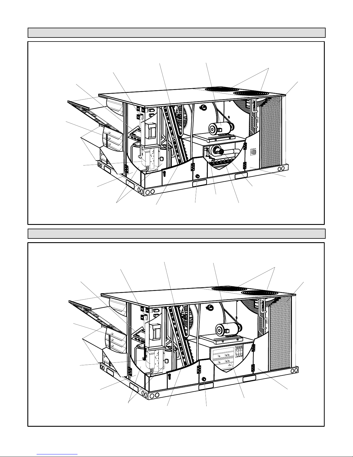
LGH092, 094, 102, 120, 122, 150 & 152 PARTS ARRANGEMENT
UNIT
CONTROLLER
ECONOMIZER
(OPTIONAL)
INVERTER (OPTIONAL)
OR INDOOR BLOWER
TRANSFORMER (575V
UNITS WITH DIRECT
DRIVE BLOWER)
OUTDOOR FAN
TRANSFORMER (094, 122,
152 460V OR 570V UNITS)
DISCONNECT /
CIRCUIT BREAKER
(FACTORY OR FIELD
INSTALLED OPTION)
COMPRESSORS
(FOUR - 20 X 25 X 2”)
EVAPORATOR
COIL
3
FILTERS
BLOWER MOTOR
(BELT DRIVE
SHOWN)
BLOWER
3
GAS VALVE
CONDENSATE
DRAIN
CONDENSER FANS
(2 FANS ON 092, 102, 120,
150 UNITS; 3 FANS ON
094, 122, 152 UNITS)
CONDENSER
COIL
HINGED
ACCESS PANEL
(OPTIONAL)
COMBUSTION
AIR INDUCER
BURNERS
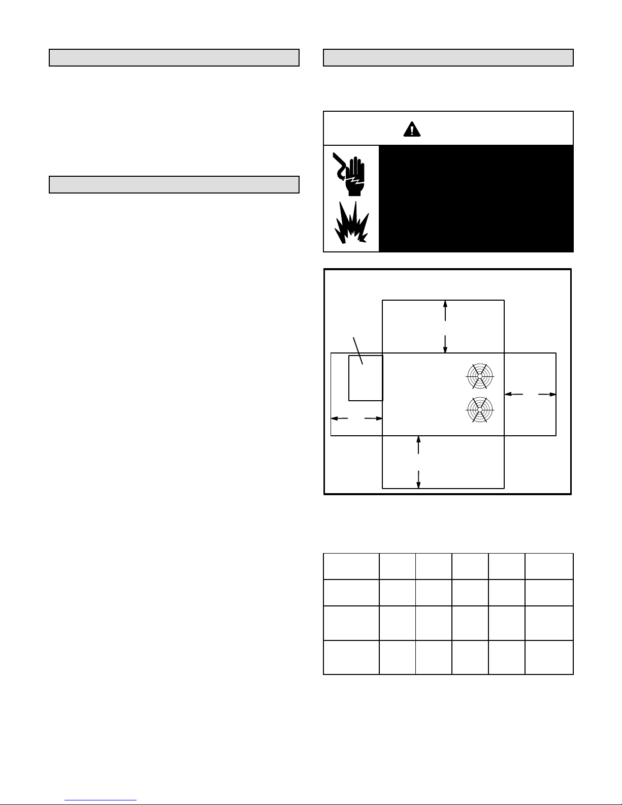
LCH092, 094, 102, 120, 122, 150 & 152 PARTS ARRANGEMENT
BLOWER MOTOR
(BELT DRIVE
SHOWN)
BLOWER
3
ELECTRIC HEAT
CONDENSATE
DRAIN
UNIT
CONTROLLER
ECONOMIZER
(OPTIONAL)
INVERTER (OPTIONAL)
OR INDOOR BLOWER
TRANSFORMER (575V
UNITS WITH DIRECT
DRIVE BLOWER)
OUTDOOR FAN
TRANSFORMER (094, 122,
152 460V OR 570V UNITS)
DISCONNECT /
CIRCUIT BREAKER
(FACTORY OR FIELD
INSTALLED OPTION)
COMPRESSORS
EVAPORATOR
COIL
3
FILTERS
(FOUR - 20 X 25 X 2”)
CONDENSER FANS
(2 FANS ON 092, 102, 120,
150 UNITS; 3 FANS ON
094, 122, 152 UNITS)
CONDENSER
COIL
HINGED
ACCESS PANEL
(OPTIONAL)
(Optional)
Page 4
Shipping and Packing List
Safety
Package 1 of 1 contains:
1- Assembled unit
IMPORTANT - Hot gas reheat units require a specific
field-provided and installed humidity sensor.
Check unit for shipping damage. Receiving party should
contact last carrier immediately if shipping damage is found.
General
These instructions are intended as a general guide
and do not supersede local codes in any way.
Authorities having jurisdiction should be consulted
before installation.
The LGH092, 094, 102, 120, 122, 150 & 152
gas/electric packaged rooftop unit is available in
130,000, 180,000, or 240,000 Btuh heating inputs.
The LCH092, 094, 102, 120, 122, 150 & 152 cooling
packaged rooftop unit is the same basic design as the
LGH unit except for the heating section. Optional
electric heat is factory- or field-installed in LCH units.
Ultra high efficiency units have a tandem refrigerant
circuit. High and standard efficiency units have two
typical circuits.
High and standard efficiency units are equipped with a
lightweight, all-aluminum condenser coil; an optional,
traditional fin/tube condenser coil is available. Ultra
high efficiency units are equipped with a traditional
fin/tube condenser coil.
High and standard efficiency units are available with an
optional hot gas reheat coil which provides a
dehumidifying mode of operation. Refer to Reheat
Operation section.
Ultra high efficiency units are available with an optional
direct drive blower or belt drive blower equipped with an
optional supply air inverter. Standard and high efficiency
units are available with a belt drive blower equipped with
an optional supply air inverter. The blower will operate at
lower speeds when demand is low and increase to higher
speeds when demand is high. Refer to Inverter and Direct
Drive Start−Up section.
The following examples show the model numbers of ten
ton units with blower options.
LGH/LCH120H4B Belt drive
LGH/LCH120H4M Belt drive with inverter
LGH/LCH122U4M Belt drive with inverter
LGH/LCH122U4E Direct drive
All units are available using R410A, an ozone-friendly HFC
refrigerant. Refer to the Cooling Start-Up section for
precautions when installing unit.
Page 5
See table 1 for unit clearances.
WARNING
Electric shock hazard and danger of
explosion. Can cause injury, death or
product or property damage. Turn off
gas and electrical power to unit before
performing any maintenance or
servicing operations on the unit. Follow
lighting instructions attached to unit
when putting unit back into operation
and after service or maintenance.
UNIT CLEARANCES
Optional
Outdoor
Air Hood
D
UNIT CLEARANCES
1
Unit
Clearance
Service
Clearance60(1524)36(914)36(914)60(1524)
Clearance to
Combus
tibles
Minimum
Operation
Clearance
Note - Entire perimeter of unit base requires support when elevated above
mounting surface.
1
Service Clearance - Required for removal of serviceable parts.
Clearance to Combustibles - Required clearance to combustible material
(gas units).
Minimum Operation Clearance - Required clearance for proper unit operation.
A
in.(mm)Bin.(mm)Cin.(mm)Din.(mm)
36
(914)
36
(914)36(914)36(914)36(914)
C
A
FIGURE 1
TABLE 1
1 (25) 1 (25) 1 (25)
B
To p
Clearance
Unob
structed
Unob
structed
Unob
structed
NOTICE
Roof Damage!
This system contains both refrigerant and oil.
Some rubber roofing material may absorb oil,
causing the rubber to swell. Bubbles in the rubber
roofing material can cause leaks. Protect the roof
surface to avoid exposure to refrigerant and oil
during service and installation. Failure to follow
this notice could result in damage to roof surface.
IMPORTANT
The Clean Air Act of 1990 bans the intentional vent
ing of refrigerant (CFC's and HCFC's) as of July 1,
1992. Approved methods of recovery, recycling or
reclaiming must be followed. Fines and/or incar
ceration may be levied for non-compliance.
Use of this unit as a construction heater or air conditioner
is not recommended during any phase of construction.
Very low return air temperatures, harmful vapors and
operation of the unit with clogged or misplaced filters will
damage the unit.
Unit Support
In downflow discharge installations, install the unit on a
non-combustible surface only. Unit may be installed on
combustible surfaces when used in horizontal discharge
applications or in downflow discharge applications when
installed on an C1CURB7*B roof mounting frame.
NOTE - Securely fasten roof frame to roof per local codes.
CAUTION
To reduce the likelihood of supply / return air by
pass and promote a proper seal with the RTU, duct
work / duct drops / diffuser assemblies must be
supported independently to the building structure.
A-Downflow Discharge Application
Roof Mounting with C1CURB7*B
1- The C1CURB7*B roof mounting frame must be
installed, flashed and sealed in accordance with the
instructions provided with the frame.
2- The C1CURB7*B roof mounting frame should be
square and level to 1/16” per linear foot (5mm per
linear meter) in any direction.
If this unit has been used for heating or cooling of
buildings or structures under construction, the following
conditions must be met or the warranty will be void:
A room thermostat must control the unit. The use of
fixed jumpers that will provide continuous heating or
cooling is not allowed.
A pre-filter must be installed at the entry to the return
air duct.
The return air duct must be provided and sealed to
the unit.
Return air temperature range between 55°F (13°C)
and 80°F (27°C) must be maintained.
Air filters must be replaced and pre-filters must be
removed upon construction completion.
The input rate and temperature rise must be set per
the unit rating plate.
The heat exchanger, components, duct system, air
filters and evaporator coil must be thoroughly
cleaned following final construction clean-up.
The unit operating conditions (including airflow,
cooling operation, ignition, input rate, temperature
rise and venting) must be verified according to these
installation instructions.
Page 6
3- Duct must be attached to the roof mounting frame
and not to the unit; supply and return plenums must
be installed before setting the unit.
Installer's Roof Mounting Frame
Many types of roof frames can be used to install the unit
depending upon different roof structures. Items to keep
in mind when using the building frame or supports are:
1- The base is fully enclosed and insulated, so an
enclosed frame is not required.
2- The frames or supports must be constructed with
non-combustible materials and should be square and
level to 1/16” per linear foot (5mm per linear meter)
in any direction.
3- Frame or supports must be high enough to prevent
any form of moisture from entering unit.
Recommended minimum frame height is 14”
(356mm).
4- Duct must be attached to the roof mounting frame
and not to the unit. Supply and return plenums must
be installed before setting the unit.
5- Units require support along all four sides of unit base.
Supports must be constructed of steel or suitably
treated wood materials.
NOTE-When installing a unit on a combustible surface for
downflow discharge applications, an C1CURB7*B roof
mounting frame is required.
B-Horizontal Discharge Applications
1- Units installed in horizontal airflow applications must
use a horizontal conversion kit K1HECK00.
2- Specified installation clearances must be maintained
when installing units. Refer to figure 1.
3- Top of support slab should be approximately 4”
(102mm) above the finished grade and located so no
run-off water from higher ground can collect around
the unit.
4- Units require support along all four sides of unit base.
Supports must be constructed of steel or suitably
treated wood materials.
Duct Connection
All exterior ducts, joints and openings in roof or building
walls must be insulated and weather-proofed with
flashing and sealing compounds in accordance with
applicable codes. Any duct passing through an
unconditioned space must be insulated.
A trap must be installed between drain connection and an
open vent for proper condensate removal. See figure 3 or
4. It is sometimes acceptable to drain condensate onto
the roof or grade; however, a tee should be fitted to the
trap to direct condensate downward. The condensate line
must be vented. Check local codes concerning
condensate disposal. Refer to pages 1 and 2 for
condensate drain location.
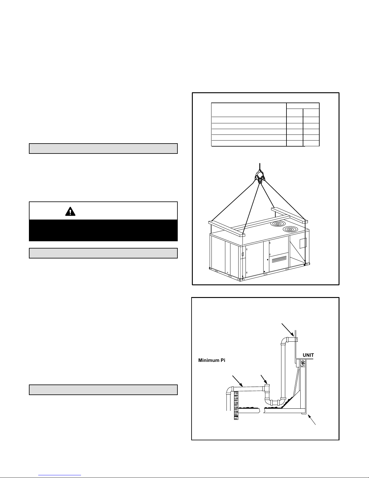
RIGGING
Unit
Gas Packaged (2 O.D. Fans)
Cooling Packaged (2 O.D. Fans)
Heat Pump Packaged
Gas Packaged (3 O.D. fans)
Cooling Packaged (3 O.D. Fans)
*Maximum weight with all available
factory-installed accessories.
CAUTION - Do not
walk on unit.
*Weight
Lbs. Kg.
1401
1366
1514
1551
1516
IMPORTANT - ALL
PANELS MUST BE IN
PLACE FOR RIGGING.
LIFTING POINT SHOULD
BE DIRECTLY ABOVE
CENTER OF GRAVITY
636
620
687
704
688
CAUTION
In downflow applications, do not drill or punch
holes in base of unit. Leaking in roof may occur if
unit base is punctured.
Rigging Unit For Lifting
Rig unit for lifting by attaching four cables to holes in unit
base rail. See figure 2.
1- Detach wooden base protection before rigging.
Note - Remove all 7 (5 brackets on units with three
outdoor fans) base protection brackets before
setting unit.
2- Connect rigging to the unit base using both holes in
each corner.
3- All panels must be in place for rigging.
4- Place field‐provided H‐style pick in place just above
top edge of unit. Frame must be of adequate
strength and length. (H-style pick prevents damage
to unit.)
FIGURE 2
CONDENSATE SIDE DRAIN CONNECTION
CAULK AROUND CONDENSATE COUPLING
NOTE - Allow clearance to
open doors when installing
condensate piping.
Minimum Pitch
1” (25 mm) per
10' (3 m) of line
OPEN VENT
UNIT
Condensate Drains
Make drain connection to the 1” N.P.T. drain coupling
provided on unit.
Note - The drain pan is made with a glass reinforced
engineered plastic capable of withstanding typical joint
torque but can be damaged with excessive force. Tighten
pipe nipple hand tight and turn an additional quarter turn.
MOUNTING
FRAME
FIGURE 3
Page 7

CONDENSATE BOTTOM DRAIN CONNECTION
UNIT
2- Remove six screws from filter access door. Refer to
figure 6.
UNITS WITH HINGED PANELS
FILTER DOOR
DRAIN PAN
CAULK AROUND
CONDENSATE COUPLING
OPEN VENT
MOUNTING
FRAME
Minimum Pitch
1” (25 mm) per 10'
(3 m) of line
FIGURE 4
Units are shipped with the drain coupling facing the front
of the unit. Condensate can be drained from the back or
bottom of the unit with the following modifications. The
unit can be installed in either downflow or horizontal air
discharge regardless of condensate drain location.
Rear Drain Connection
1- Open blower and heat access doors. See figure 5.
CONDENSATE
DRAIN MULLION
REMOVE
THREE
SCREWS
(PER HINGE)
FIGURE 6
3- Open filter access door hinges and carefully remove
door.
4- Remove eight screws holding condensate drain
mullion and remove mullion.
5- Lift front edge of the drain pan (to clear bottom drain
plug) and slide drain pan out of unit. See figure 7.
FILTER
ACCESS DOOR
BLOWER
ACCESS DOOR
CONDENSATE
DRAIN MULLION
FIGURE 5
HEAT
ACCESS DOOR
DRAIN PAN
FIGURE 7
6- Make sure the cap over the unit bottom drain hole is
secure.
7- Rotate the drain pan until the downward slope is
toward the back of the unit. Slide the drain pan back
into the unit. Be careful not to dislodge the cap over
the bottom drain hole.
8- From the back side of the unit, pull the drain pan
coupling through the rear condensate opening.
9- Replace the condensate drain mullion and reinstall
eight screws.
10- Reinstall filter door on hinges.
Page 8
Bottom Drain Connection
1- Open blower and heat access doors. See figure 5.
2- Remove six screws from filter access door. Refer to
figure 6.
3- Open filter access door hinges and carefully remove
door.
4- Remove eight screws holding condensate drain
mullion and remove mullion.
5- Lift front edge of the drain pan (to clear bottom drain
plug) and slide drain pan out of unit. See figure 7.
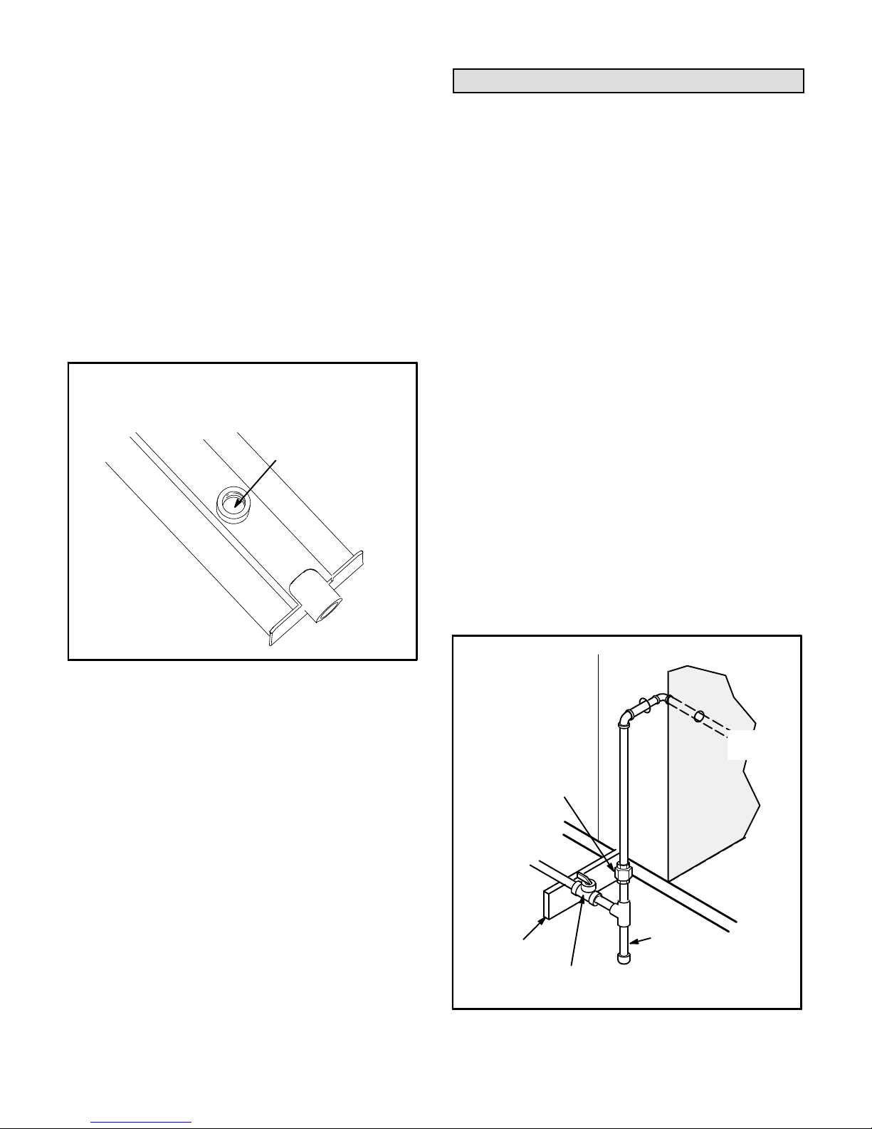
6- Turn the drain pan upside down and drill a pilot hole
through the bottom of the drain pan in the center of
the coupling. See figure 8.
BOTTOM CONDENSATE DRAIN
CAUTION: Be careful not to
damage the coupling threads
when drilling the hole.
DRILL A PILOT
HOLE IN CENTER
OF COUPLING
Connect Gas Piping (Gas Units)
Before connecting piping, check with gas company or
authorities having jurisdiction for local code
requirements. When installing gas supply piping, length
of run from gas meter must be considered in determining
pipe size for 0.5” w.c. (.12kPa) maximum pressure drop.
Do not use supply pipe smaller than unit gas connection.
For natural gas units, operating pressure at the unit gas
connection must be a minimum of 4.7” w.c. (1.17kPa)
and a maximum of 10.5” (2.60kPa) w.c. For LP/propane
gas units, operating pressure at the unit gas connection
must be a minimum of 10.5” w.c. (2.61kPa) and a
maximum of 13.0” w.c. (3.23kPa).
When making piping connections a drip leg should be
installed on vertical pipe runs to serve as a trap for
sediment or condensate. A 1/8” N.P.T. plugged tap is
located on gas valve for test gauge connection. Refer to
Heating Start-Up section for tap location. Install a ground
joint union between the gas control manifold and the main
manual shut-off valve. See figure 9 for gas supply piping
entering outside the unit. Figure 10 shows bottom gas
entry piping through the curb. Figure 11 shows bottom
gas entry piping through the unit.
After drilling the pilot
hole, drill a 7/8” hole from
the inside of the pan.
FIGURE 8
7- From the inside of the pan, use a Vari-Bit® bit to
enlarge the hole to 7/8”. Do not damage coupling
threads.
8- Remove the cap over the unit bottom drain hole.
9- Slide the drain pan back into the unit.
10- From the back side of the unit, pull the drain pan
coupling through the rear condensate opening.
11- From the front side of the unit, move the drain pan
until the bottom coupling settles into the unit bottom
drain opening. Once in place, check to make sure the
coupling is still positioned through the rear
condensate drain hole.
12- Use a field-provided 1” plug to seal side drain
connection.
13- Replace the condensate drain mullion and reinstall
eight screws.
14- Reinstall filter door on hinges.
Page 9
Compounds used on threaded joints of gas piping shall be
resistant to the action of liquified petroleum gases.
OUTSIDE OF UNIT GAS PIPE CONNECTION
TO GAS
VALV E
GROUND
JOINT UNION
TO GAS
SUPPLY
GAS PIPING
SUPPORT
MANUAL MAIN
SHUT-OFF VALVE
DRIP LEG
(REFER TO
LOCAL CODES)
FIGURE 9
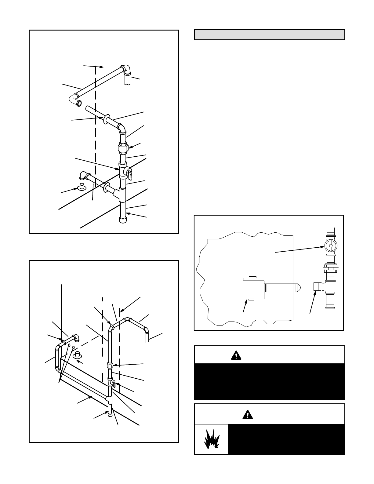
BOTTOM ENTRY GAS PIPING
THROUGH THE CURB
MULLION BETWEEN
HEAT AND COMPRES
SOR SECTIONS
4” NIPPLE
GROMMET
ALL ELBOWS ARE 3/4”
MANUAL MAIN
SHUT-OFF VALVE
TO GAS
VALV E
4” NIPPLE
5” NIPPLE
7-1/2” NIPPLE
GROUND
JOINT UNION
4” NIPPLE
Pressure Test Gas Piping (Gas Units)
When pressure testing gas lines, the gas valve must
be disconnected and isolated. Gas valves can be
damaged if subjected to more than 0.5 psig (3.48kPa).
See figure 12.
NOTE-Codes may require that manual main shut-off
valve and union (furnished by installer) be installed in
gas line external to unit. Union must be of the ground
joint type.
After all connections have been made, check all piping
connections for gas leaks. Also check existing unit gas
connections up to the gas valve; loosening may occur
during installation. Use a leak detection solution or other
preferred means. Do not use matches candles or other
sources of ignition to check for gas leaks.
TO GAS
SUPPLY
ROOF
MOUNTING
FRAME
ALL ELBOWS ARE 3/4”
10” NIPPLE
GROMMET
7”
NIPPLE
ALTERNATE
KNOCKOUTS
ROOF MOUNTING
FRAME
7-1/2” NIPPLE
10” NIPPLE
FIGURE 10
BOTTOM GAS ENTRY
THROUGH THE UNIT
MULLION BETWEEN
HEAT AND COMPRES
GROMMET
TO GAS
SUPPLY
DRIP LEG
5” NIPPLE
3” NIPPLE
FIGURE 11
3-1/2” NIPPLE
3” NIPPLE
DRIP LEG
SOR SECTIONS
4” NIPPLE
4” NIPPLE
TO GAS
VALV E
GROUND
JOINT UNION
4” NIPPLE
MANUAL MAIN
SHUT-OFF VALVE
3-1/2” NIPPLE
NOTE-In case emergency shut down is required, turn off
the main manual shut-off valve and disconnect main
power to unit. These devices should be properly labeled
by the installer.
PRESSURE TEST GAS LINE
MANUAL MAIN
SHUT-OFF VALVE
GAS VALVE
CAP
FIGURE 12
CAUTION
Some soaps used for leak detection are corrosive
to certain metals. Carefully rinse piping thoroughly
after leak test has been completed. Do not use
matches, candles, flame or othe sources of ignition
to check for gas leaks.
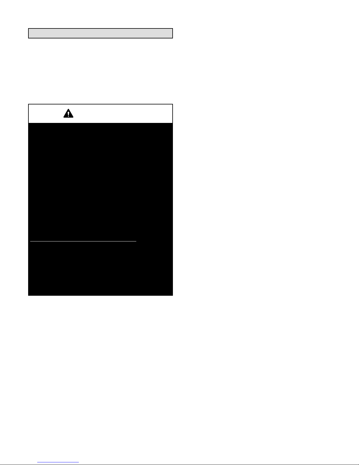
WARNING
Danger of explosion. Can cause injury
or product or property damage. Do not
use matches, candles, flame or other
sources of ignition to check for leaks.
Page 10
High Altitude Derate
CONTROL WIRING
Locate the high altitude conversion sticker in the unit
literature bag. Fill out the conversion sticker and affix next
to the unit nameplate.
Refer to table 2 for high altitude adjustments.
TABLE 2
HIGH ALTITUDE DERATE
Altitude Ft.* Gas Manifold Pressure
2000-4500 See Unit Nameplate
4500 And Above Derate 2% / 1000 Ft. Above Sea Level
*Units installed at 0-2000 feet do not need to be modified.
NOTE ‐ This is the only permissible derate for these units.
Electrical Connections
POWER SUPPLY
Do not apply power or close disconnect switch until
installation is complete. Refer to start-up directions.
Refer closely to unit wiring diagram.
Refer to unit nameplate for minimum circuit ampacity
and maximum fuse size.
1- 230/460/575 volt units are factory wired. For 208V
supply, disconnect the orange wire (230V) at all
control power transformer(s). Reconnect the red
wire (208V). Tape the exposed end of the 230V
orange wire.
2- Route power through the bottom power entry area.
On gas units or units with electric heat, connect
power wiring to TB2. On cooling only units,
connect power to F4. If unit contains an optional
factory-installed circuit breaker or disconnect
switch, connect line voltage to CB10 or S48. See
unit wiring diagram.
3- Connect separate 120v wiring to optional GFCI
outlet.
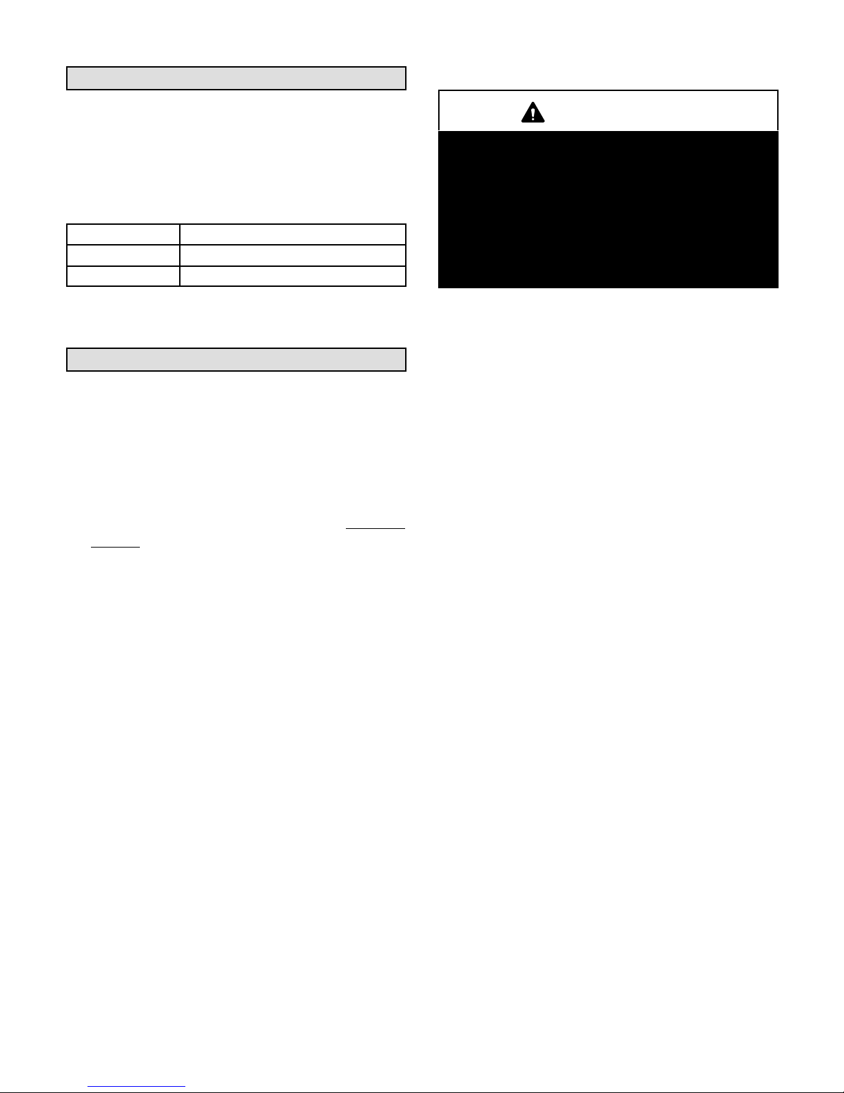
CAUTION
Electrostatic discharge can affect electronic com
ponents. Take precautions during unit installation
and service to protect the electronic controls. Pre
cautions will help to avoid control exposure to elec
trostatic discharge by putting the unit, the control
and the technician at the same electrostatic poten
tial. Neutralize electrostatic charge by touching
hands and all tools on an unpainted unit surface,
such as the gas valve or blower deck, before per
forming any service procedure.
A-Thermostat Location
Room thermostat mounts vertically on a standard 2” X 4”
handy box or on any non-conductive flat surface.
Locate thermostat approximately 5 feet (1524mm)
above the floor in an area with good air circulation at
average temperature. Avoid locating the room
thermostat where it might be affected by:
-drafts or dead spots behind doors and in corners
-hot or cold air from ducts
-radiant heat from sun or appliances
-concealed pipes and chimneys
B-Control Wiring
The Unit Controller will operate the unit from a
thermostat or room sensor based on the System
Mode. The default System Mode is the thermostat
mode. Refer to the Unit Controller Installation and
Setup Guide to change the System Mode. Use the
menu navigation arrows and select button; SETTINGS
> CONTROL. Options are: “WIRED THERMOSTAT”
and “NETWORK”.
Thermostat Mode
1- Route thermostat cable or wires from subbase to
control area above compressor (refer to unit
dimensions to locate bottom and side power entry).
IMPORTANT - Unless field thermostat wires are rated
for maximum unit voltage, they must be routed away
from line voltage wiring. Use wire ties located on the front
border of the control panel to secure thermostat cable.
Use18 AWG wire for all applications using remotely
installed electro-mechanical and electronic
thermostats.
Page 11
2- Install thermostat assembly in accordance with
instructions provided with thermostat.
3- Connect thermostat wiring to the bottom of the Unit
Controller.
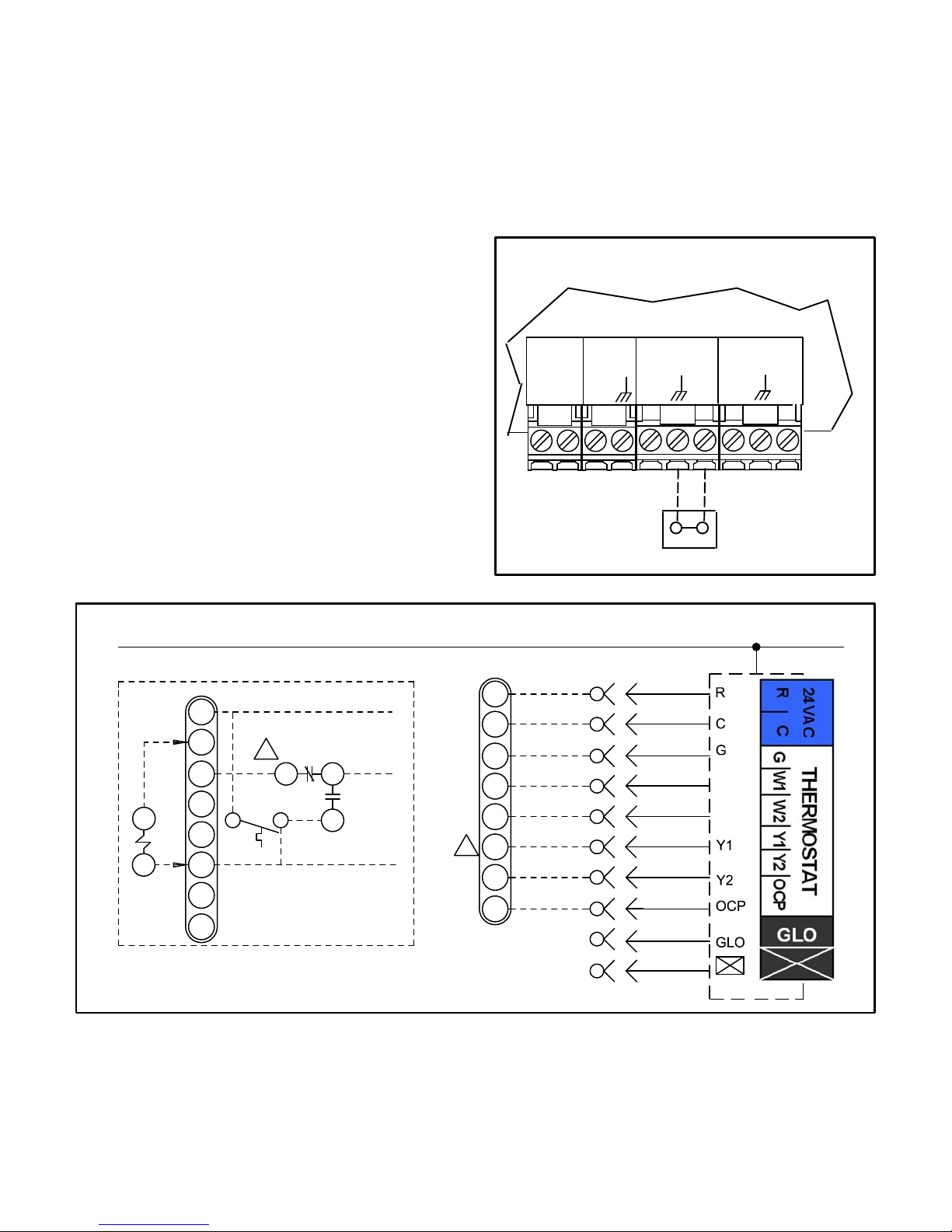
4- Wire as shown in figure 14 for electro-mechanical
and electronic thermostats. If using other
temperature control devices or energy management
systems see instructions and wiring diagram
provided by manufacturer.
IMPORTANT-Terminal connections at the Unit Controller
must be made securely. Loose control wire connections
may allow unit to operate but not with proper response to
room demand.
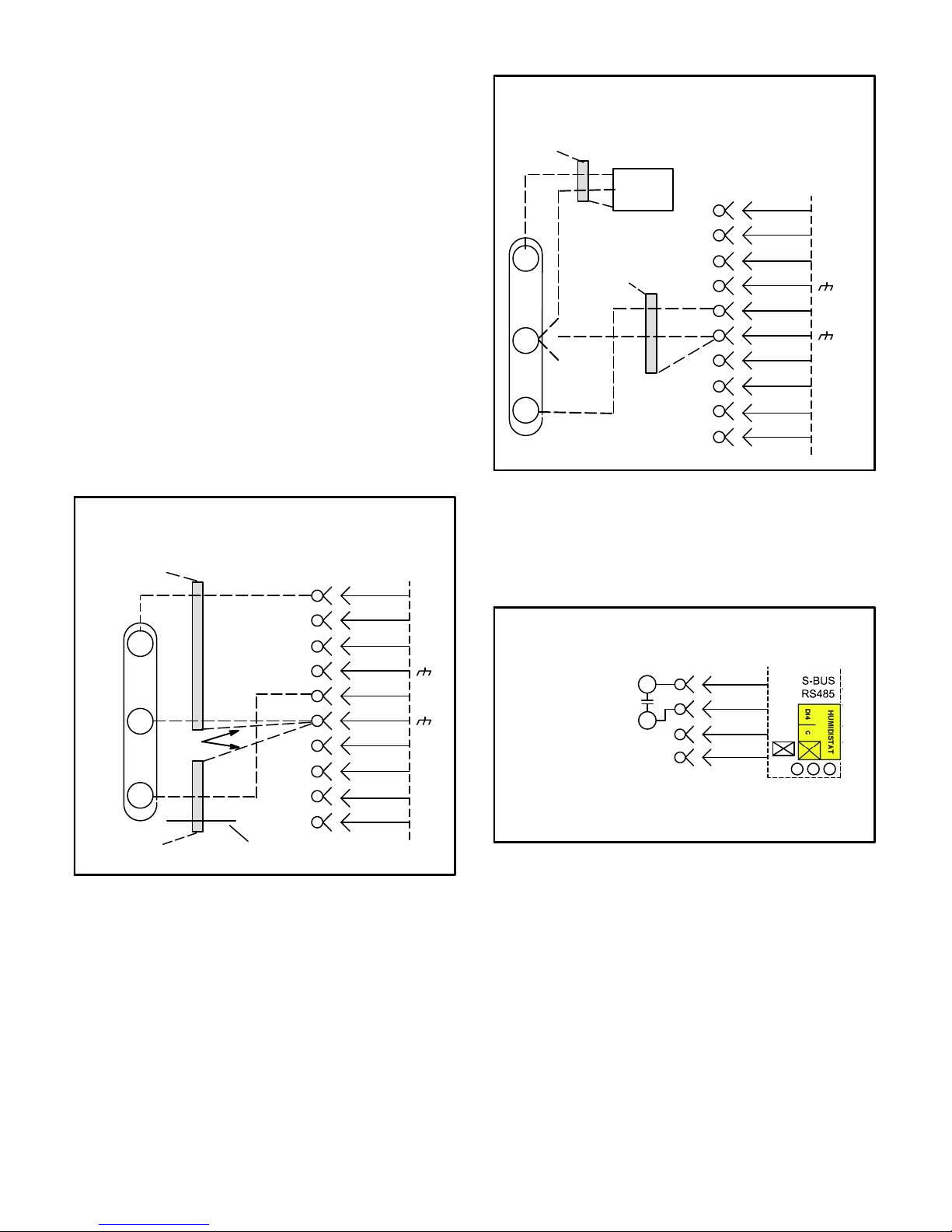
Room Sensor Mode
The Unit Controller will operate heating and cooling
based on the Unit Controller internal setpoints and the
temperature from the A2 room sensor. An optional
Network Control Panel (NCP) can also be used to provide
setpoints. A thermostat or return air sensor can be used
as a back-up mode. Make room sensor wiring
connections as shown in figure 13.
be used to initiate dehumidification instead of a
sensor.
2- Make wiring connections as shown in figure 14 for
thermostat mode or figure 13 for room sensor
mode. In addition, connect either a humidity
sensor or a dehumidification input. See figure 15
or 16 for humidity sensor wiring or figure 17 for
dehumidification input wiring.
FIELD WIRING IN ROOM SENSOR MODE
(Room Sensor Mode)
UNIT CONTROLLER
24VAC
RC
SENSOR
IAQ
AI1
SENSOR
HUM
TMP
OUTPUTS
D01
D02
J298
C-Hot Gas Reheat Units Only -
1- Install humidity sensor in accordance with
instructions provided with sensor. A DDC input may
24 VOLT FIELD WIRING IN THERMOSTAT MODE
24 V POWER
TO UNIT CONTROLLER
R
C
G
B
K55
A
TO PROVIDE SUPERMARKET REHEAT SCHEME
USE S86 DEHUMIDISTAT AND K55.
W1
W2
Y1
Y2
OCP
THERMOSTAT INPUTS
TO R
2
2
7
K55−1
TO G
S86
5
TO Y1
ALL OTHER THERMOSTAT
SIGNALS REMAIN CONNECTED
AS SHOWN ON THE RIGHT.
A2 SENSOR
FIGURE 13
J297A
R
C
G
W1
W2
Y1
2
Y2
OCP
P297
1
A55
P262
10
J262C
2
B
11
3
4
5
W1
W2
12
6
7
8
C
9
10
FIGURE 14
Page 12
Humidity Sensor Cable Applications:
Wire runs of 50 feet (mm) or less:
Use two separate shielded cables containing 20AWG
minimum, twisted pair conductors with overall shield.
Belden type 8762 or 88760 (plenum) or equivalent.
Connect both cable shield drain wires to the Unit
Controller as shown in figure 15.
Wire runs of 150 feet (mm) or less:
Use two separate shielded cables containing 18AWG
minimum, twisted pair conductors with overall shield.
Belden type 8760 or 88760 (plenum) or equivalent.
Connect both cable shield drain wires to the Unit
Controller as shown in figure 15.
Wire runs over 150 feet (mm):
Use a local, isolated 24VAC transformer such as Lennox
cat #18M13 (20VA minimum) to supply power to RH
sensor as shown in figure 16. Use two shielded cables
containing 20AWG minimum, twisted pair conductors
with overall shield. Belden type 8762 or 88760 (plenum)
or equivalent.
FIELD WIRING HOT GAS REHEAT UNITS (Using A
Humidity Sensor With Less Than 150 Ft. Wire Runs)
NOT
CONNECTED
A91
VIN
GND
VO
NOT
CONNECTED
DRAIN
J298A
UNUSED
WIRE
1
2
B
3
4
C
5
6
7
D
8
9
10
A55 UNIT
CONTROLLER
P298
R
C
AI-1
HUM
TMP
DO-1
C
DO-2
DI-1
FIGURE 15
FIELD WIRING HOT GAS REHEAT UNITS (Using A
Humidity Sensor With More than 150Ft. Wire Runs)
NOT
CONNECTED
A91
VIN
GND
ISOLATED 24V
TRANSFORMER
DRAIN
NOT
CONNECTED
J298A
A55 UNIT
CONTROLLER
P298
1
2
B
3
4
C
5
R
C
AI-1
HUM
6
7
TMP
D
VO
8
9
10
DO-1
C
DO-2
DI-1
FIGURE 16
FIELD WIRING HOT GAS REHEAT UNITS
(Using A Dehumidification Switch)
J299
R
DI−4
C
DEHUMIDIFICATION
SWITCH
Use 24 VAC (R) from any terminal
available on J299−2, −5, or −7.
7
8
9
10
FIGURE 17
Page 13
Blower Operation and Adjustments
Belt Drive With Supply Air Inverter or Direct Drive
Units - The blower rotation will always be correct on units
equipped with an inverter or a direct drive blower.
Checking blower rotation is not a valid method of
determining voltage phasing for incoming power.
IMPORTANT
Three Phase Scroll Compressor Voltage Phasing
Three phase scroll compressors must be phased se
quentially to ensure correct compressor and blower*
rotation and operation. Compressor and blower are
wired in phase at the factory. Power wires are colorcoded as follows: line 1-red, line 2-yellow, line 3-blue.
1-Observe suction and discharge pressures and blow
er* rotation on unit start-up.
2-Suction pressure must drop, discharge pressure must
rise and blower* rotation must match rotation marking.
If pressure differential is not observed or blower* rota
tion is not correct:
3-Disconnect all remote electrical power supplies.
4-Reverse any two field-installed wires connected to
the line side of S48 disconnect or TB13 terminal strip.
Do not reverse wires at blower contactor.
5-Make sure the connections are tight.
Discharge and suction pressures should operate at
their normal start‐up ranges.
*Supply air inverter driven motors should rotate in the
correct direction; verify scroll compressor rotation
separately. Contact technical support if the blower is
rotating incorrectly.
Units Equipped With Belt Drive Blowers Controlled
by an Inverter OR Direct Drive Blowers Equipped
With Optional Voltage or Phase Detection - The Unit
Controller checks the incoming power during start-up. If
the voltage or phase is incorrect, the Unit Controller will
display an alarm and the unit will not start.
A-Blower Operation
Note - On units with staged blowers, use the Unit
Controller to start the blower. Refer to the appropriate
start-up section.
Initiate blower only (G) demand at thermostat according
to instructions provided with thermostat. Unit will cycle on
thermostat demand. The following steps apply to
applications using a typical electro-mechanical
thermostat.
1- Blower operation is manually set at the thermostat
subbase fan switch. With fan switch in ON position,
blowers will operate continuously.
2- With fan switch in AUTO position, the blowers will
cycle with demand. Blowers and entire unit will be off
when system switch is in OFF position.
B-Blower Access
The blower assembly is secured to a sliding frame which
allows the blower motor assembly to be pulled out of the
unit. See figure 18, 19 or 20.
Belt Drive Blowers
1- Loosen the reusable wire tie which secures the
blower wiring to the blower motor mounting plate.
2- Remove and retain screws on either side of sliding
frame. Pull frame toward outside of unit.
3- Slide frame back into original position when finished
servicing. Reattach the blower wiring in the previous
location on the blower motor base using the wire tie.
4- Replace retained screws on either side of the sliding
frame.
Direct Drive Blowers
1- Loosen the reusable wire tie which secures the
controls and high voltage blower wiring to the blower
housing.
2- Remove and retain screws in front and on either side
of blower housing. Pull frame toward outside of unit.
3- Slide frame back into original position when finished
servicing. Reattach the blower wiring in the previous
location on the blower motor base using the wire tie.
4- Replace retained screws in front and on either side of
the blower housing.
Page 14
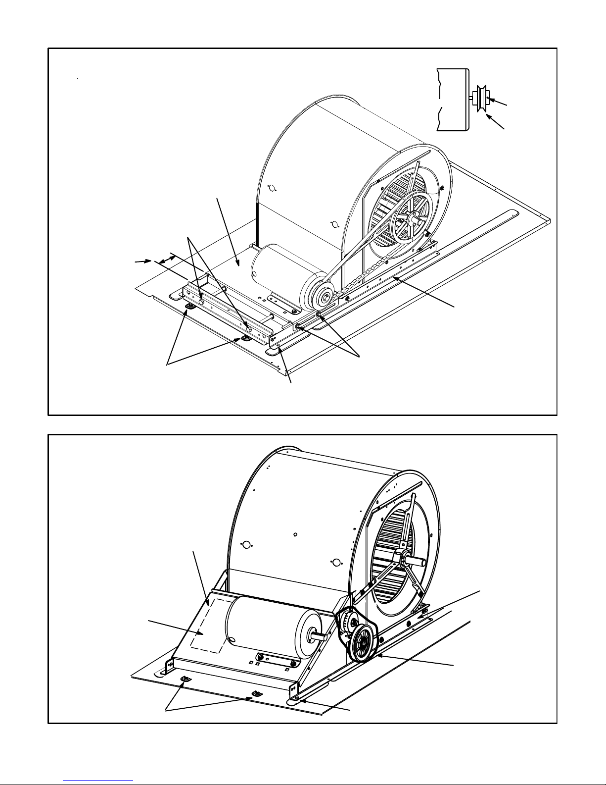
TO INCREASE BELT TENSION
1- Loosen four bolts securing motor mounting base
to frame.
2- Turn adjusting bolt to the right, or clockwise, to
move the motor away from the blower housing.
IMPORTANT - Gap between end of frame and motor
mounting base should be equal at both ends, i.e. par
allel along gap.
3- Tighten four bolts securing motor mounting base
to frame.
4- Relieve tension on two adjusting bolts.
MOTOR MOUNTING
BASE
BELT ADJUSTING BOLTS
- TURN CLOCKWISE
TO TIGHTEN BELT
GAP BETWEEN
EDGES SHOULD BE
PARALLEL ON BOTH
ENDS BEFORE
TIGHTENING MOTOR
MOUNTING BASE IN
PLACE
BELT DRIVE BLOWER ASSEMBLY
BLOWER
HOUSING
MOTOR
SIDE VIEW
MOTOR
BLOWER
FRAME
ALLEN
SCREW
PULLEY
REMOVE TWO SCREWS
TO COMPLETELY SLIDE
BLOWER OUT OF UNIT
BELT DRIVE BLOWER ASSEMBLY WITH TENSIONER (VIEW SHOWN WITHOUT BELT)
TO INCREASE OR
DECREASE BELT
TENSION, REFER TO
INSTALLATION LABEL
LOOSEN BEFORE
ADJUSTING BELT TENSION
(TWO EACH SIDE)
REMOVE TWO SCREWS ON EACH
SIDE TO SLIDE FRAME PARTIALLY
OUT OF UNIT FOR SERVICE ACCESS
FIGURE 18
BLOWER
HOUSING
MOTOR
MOUNTING
BASE
BLOWER
FRAME
MOTOR
TO COMPLETELY REMOVE
BLOWER ASSEMBLY FROM
UNIT, TWO ADDITIONAL
SCREWS MUST BE REMOVED
TENSIONER
REMOVE TWO SCREWS ON EACH
SIDE TO SLIDE FRAME PARTIALLY
OUT OF UNIT FOR SERVICE ACCESS
FIGURE 19
Page 15
 Loading...