

Lennox LGH 036, LGH 060, LGH 072, LCH 036, LCH 048 Installation Instructions Manual
...
USER'S INFORMATION
MANUAL
LGH/LCH036, 048, 060, 072
(3, 4, 5 & 6 Tons)
This book includes the following manuals:
UNIT INSTALLATION INSTRUCTIONS 507155-01
OWNER'S MANUAL 506372-01
AGENCY MANUAL 506373-01
IMC MANUAL 506215-01
ECONOMIZER INSTRUCTIONS 507030-01
IMC MODULE INSTRUCTIONS (LONTALK GATEWAY) 506217-01
IMC MODULE INSTRUCTIONS (LONTALK PRODIGY) 506693-01
WARRANTY W-022-L3

Litho U.S.A.
2013
WARNING
Improper installation, adjustment, alteration, ser
vice or maintenance can cause property damage,
personal injury or loss of life. Installation and ser
vice must be performed by a licensed professional
HVAC installer or equivalent, service agency, or the
gas supplier
INSTALLATION
INSTRUCTIONS
LGH/LCH036, 048,
060 & 072
3, 4, 5 and 6 Ton
GAS AND COOLING PACKAGED UNITS
507155-01
4/2013
Supersedes 507085-01
Table Of Contents
Dimensions Page 2.................................
Parts Arrangements Page 3.........................
Shipping and Packing List Page 4....................
General Page 4....................................
Requirements Page 4...............................
Unit Support Page 5................................
Duct Connection Page 5............................
Rigging Unit For Lifting Page 5.......................
Horizontal Air Discharge Page 6......................
Condensate Drains Page 6..........................
Gas Piping Page 8.................................
Pressure Test Gas Piping Page 9.....................
RETAIN THESE INSTRUCTIONS FOR FUTURE REFERENCE
High Altitude Derate Page 9.........................
Electrical Connections Page 9.......................
Blower Operation and Adjustments Page 12............
Cooling Start-Up Page 28............................
Gas Heat Start-Up Page 38...........................
Heating Operation and Adjustments Page 39............
Electric Heat Start-Up Page 39........................
Ventilation Control Board Start-Up Page 40.............
Hot Gas Reheat Startup Page 42......................
Service Page 43....................................
CAUTION
Danger of sharp metallic edges. Can cause injury.
Take care when servicing unit to avoid accidental
contact with sharp edges.
L
E
N
N
O
X
L
E
N
N
O
X
04/13
*2P0413*
LG SHOWN
LL
E
N
N
O
X
507155-01
*P507155-01*
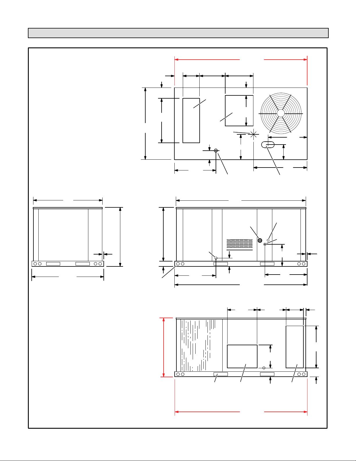
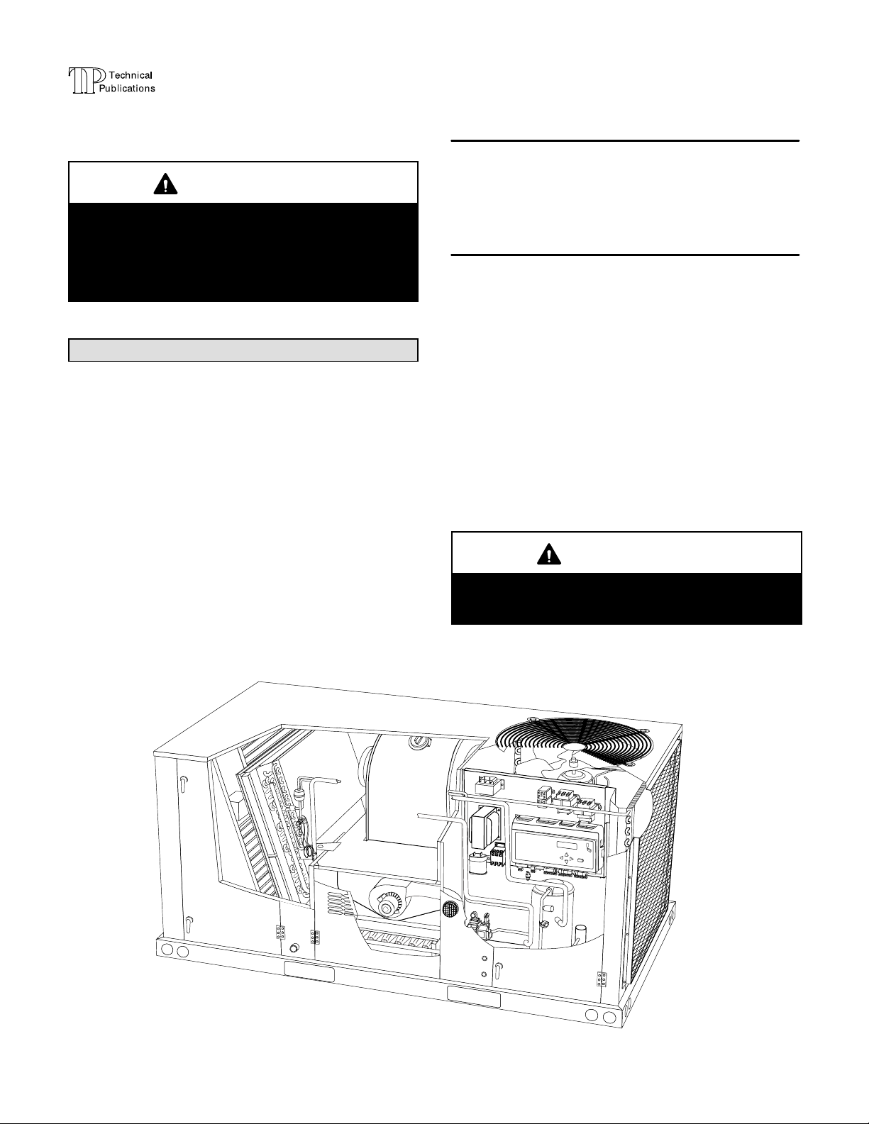
LGH/LCH036, 048, 060, & 072 DIMENSIONS in. - Gas heat section shown
85−1/4 (2165)
5−5/8
11
(143)
(279)
16−1/4
(413)
18
(457)
BASE
45
(1143)
47 (1192)
BASE
END VIEW
1 (25)
AA
7 (178)
29
(737)
47 (1192)
BASE
DD
35−3/8 (899) 036 thru 048
38−7/8 (987) 036 thru 048
46−7/8 (1191) 060 thru 072
LIFTING HOLES
(For rigging)
43−3/8 (1102) 060 thru 072
3−1/2 (89)
BOTTOM
RETURN
OPENING
BOTTOM
OPENING
6−5/8
(168)
26−1/2
(673)
CONDENSATE OUTLET
CONDENSATE
OUTLET
(EITHER SIDE)
26−1/2
(673)
AIR
SUPPLY
AIR
CENTER
OF
GRAVITY
BOTTOM
TOP VIEW (Base)
83−1/4
(2115)
FLUE/VENT
OUTLET
5−1/2
(140)
SIDE VIEW
19−1/2
5 (102)
20
(508)
FF
85−1/4 (2165)
BASE
(495)
25−3/4
(654)
9−1/2
(241)
EE
BOTTOM POWER ENTRY
3 X 8 (76 X 203)
ELECTRICAL
INLET
GAS
INLET
15 (381)
27
(686)
11
18−3/8
(467)
(279)
BB
CC
1 (25)
2 (51)
38−7/8 (987) 036 thru 048
46−7/8 (1191) 060 thru 072
FORKLIFT SLOTS
(Front, Back and
Blower End)
Page 2
HORIZONTAL
SUPPLY AIR
OPENING
BACK VIEW
85−1/4 (2165)
BASE
LGH/LCH036, 048, 060, 072
20
(508)
HORIZONTAL
5−1/2
RETURN AIR
(140)
OPENING
(Without Economizer)
29
(737)
5−1/2
(140)
LGH036, 048, 060, & 072 PARTS ARRANGEMENT
FILTERS (4)
036, 048:16 X 20 X 2”
060, 072: 20 X 20 X 2”
ECONOMIZER
(OPTIONAL)
CONDENSATE
DRAIN
EVAPORATOR
L
E
N
N
O
X
L
E
N
N
O
X
COMBUSTION
AIR INDUCER
COIL
BURNERS
REHEAD COIL
(OPTIONAL)
BLOWER
GAS VALVE
TXV
(DIRECT DRIVE SHOWN)
UNIT
CONTROLLER
BLOWER
MOTOR
LL
E
N
N
O
X
COMPRESSOR
CONDENSER
FAN
COIL
GUARDS
(OPTIONAL)
CONDENSER
COIL
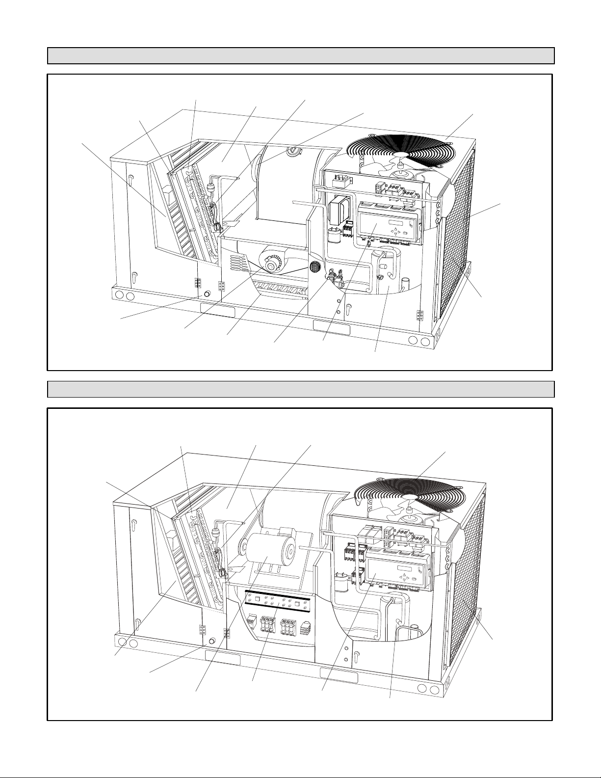
LCH036, 048, 060, & 072 PARTS ARRANGEMENT
REHEAT COIL
(OPTIONAL)
ELECTRIC HEAT
(Optional)
TXV
BLOWER
UNIT
CONTROLLER
FILTERS (4)
036, 048:16 X 20 X 2”
060, 072: 20 X 20 X 2”
ECONOMIZER
(OPTIONAL)
CONDENSATE
DRAIN
EVAPORATOR
COIL
L
E
N
N
O
X
L
E
N
N
O
X
BLOWER
MOTOR
(BELT DRIVE SHOWN)
LL
E
N
N
O
X
COMPRESSOR
CONDENSER
FAN
CONDENSER
COIL
LGH/LCH036, 048, 060, 072
Page 3
Shipping and Packing List
Package 1 of 1 contains:
1- Assembled unit
Check unit for shipping damage. Receiving party should
contact last carrier immediately if shipping damage is found.
General
These instructions are intended as a general guide
and do not supersede local codes in any way.
Authorities having jurisdiction should be consulted
before installation.
The LGH units are available in three heating inputs. The
LCH cooling packaged rooftop unit is the same basic
design as the LGH unit except for the heating section.
Optional electric heat is available for LCH units. LGH and
LCH units have identical refrigerant circuits with
respective 3, 4, 5, and 6 ton cooling capacities.
Units come standard with a lightweight, all-aluminum
condenser coil. Units are also available with an optional
fin/tube condenser coil.
In addition to standard heating and cooling, hot gas
reheat units provide a dehumidifying mode of operation.
Refer to Reheat Operation section.
An optional factory-installed ventilation control board
(VCB) is available. Units equipped with a VCB allow the
installer to enter the design-specified supply air and
outdoor air CFM into the Unit Controller. See VCB
Start-Up section.
Availability of units and options varies by brand.
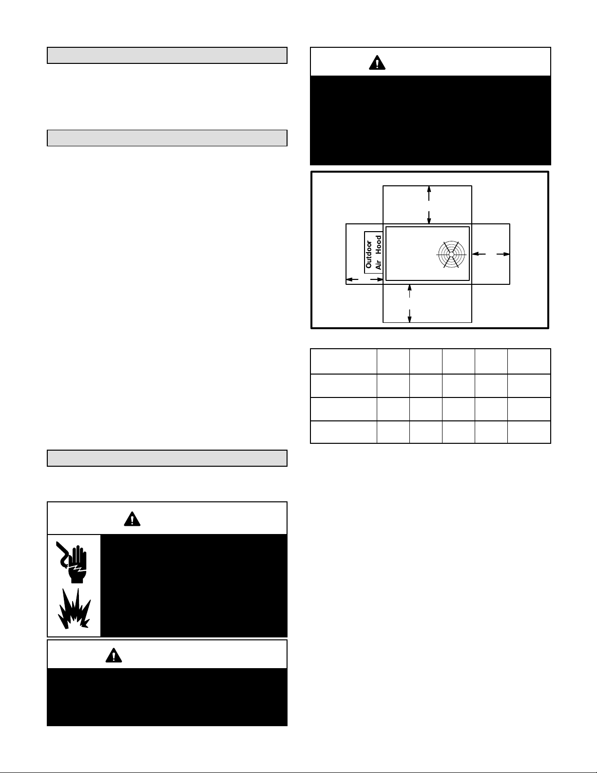
Requirements
See figure 1 for unit clearances.
WARNING
Electric shock hazard and danger of
explosion. Can cause injury, death or
product or property damage. Turn off
gas and electrical power to unit before
performing any maintenance or
servicing operations on the unit. Follow
lighting instructions attached to unit
when putting unit back into operation
and after service or maintenance.
IMPORTANT
The Clean Air Act of 1990 bans the intentional vent
ing of refrigerant (CFC's and HCFC's) as of July 1,
1992. Approved methods of recovery, recycling or
reclaiming must be followed. Fines and/or incar
ceration may be levied for non-compliance.
NOTICE
Roof Damage!
This system contains both refrigerant and oil.
Some rubber roofing material may absorb oil,
causing the rubber to swell. Bubbles in the rubber
roofing material can cause leaks. Protect the roof
surface to avoid exposure to refrigerant and oil
during service and installation. Failure to follow
this notice could result in damage to roof surface.
UNIT CLEARANCES
C
B
D
A
FIGURE 1
1
Unit
Clearance
Service
Clearance
Clearance to
Combustibles36(914)1(25)1(25)1(25)
Minimum Opera
tion Clearance36(914)36(914)36(914)36(914)
Note - Entire perimeter of unit base requires support when elevated above
mounting surface.
1
Service Clearance - Required for removal of serviceable parts.
Clearance to Combustibles - Required clearance to combustible material
(gas units).
Minimum Operation Clearance - Required clearance for proper unit operation.
Use of this unit as a construction heater or air conditioner
is not recommended during any phase of construction.
Very low return air temperatures, harmful vapors and
operation of the unit with clogged or misplaced filters will
damage the unit.
If this unit has been used for heating or cooling of
buildings or structures under construction, the following
conditions must be met or the warranty will be void:
A room thermostat must control the unit. The use of
fixed jumpers that will provide continuous heating or
cooling is not allowed.
A pre-filter must be installed at the entry to the return
air duct.
The return air duct must be provided and sealed to
the unit.
Return air temperature range between 55°F (13°C)
and 80°F (27°C) must be maintained.
Page 4
A
in.(mm)Bin.(mm)Cin.(mm)Din.(mm)
48
(1219)36(914)36(914)36(914)
LGH/LCH036, 048, 060, 072
To p
Clearance
Unob
structed
Unob
structed
Unob
structed

Air filters must be replaced and pre-filters must be
removed upon construction completion.
The input rate and temperature rise must be set per
the unit rating plate.
The heat exchanger, components, duct system, air
filters and evaporator coil must be thoroughly
cleaned following final construction clean-up.
The unit operating conditions (including airflow,
cooling operation, ignition, input rate, temperature
rise and venting) must be verified according to these
installation instructions.
Unit Support
In downflow discharge installations, install the unit on a
non-combustible surface only. Unit may be installed on
combustible surfaces when used in horizontal discharge
applications or in downflow discharge applications when
installed on an T1CURB / C1CURB / E1CURB roof
mounting frame.
NOTE - Securely fasten roof frame to roof per local codes.
A-Downflow Discharge Application
Roof Mounting with T1CURB / C1CURB / E1CURB
1- The roof mounting frame must be installed, flashed
and sealed in accordance with the instructions
provided with the frame.
2- The roof mounting frame should be square and level
to 1/16” per linear foot (5mm per linear meter) in any
direction.
5- Units require support along all four sides of unit base.
Supports must be constructed of steel or suitably
treated wood materials.
NOTE-When installing a unit on a combustible surface for
downflow discharge applications, a T1CURB / C1CURB /
E1CURB roof mounting frame is required.
B-Horizontal Discharge Applications
1- Units which are equipped with an optional
economizer and installed in horizontal airflow
applications must use a horizontal conversion kit.
2- Specified installation clearances must be maintained
when installing units. Refer to figure 1.
3- Top of support slab should be approximately 4”
(102mm) above the finished grade and located so no
run-off water from higher ground can collect around
the unit.
4- Units require support along all four sides of unit base.
Supports must be constructed of steel or suitably
treated wood materials.
Duct Connection
All exterior ducts, joints and openings in roof or building
walls must be insulated and weather-proofed with
flashing and sealing compounds in accordance with
applicable codes. Any duct passing through an
unconditioned space must be insulated.
3- Duct must be attached to the roof mounting frame
and not to the unit; supply and return plenums must
be installed before setting the unit.
Installer's Roof Mounting Frame
Many types of roof frames can be used to install the unit
depending upon different roof structures. Items to keep
in mind when using the building frame or supports are:
1- The base is fully enclosed and insulated, so an
enclosed frame is not required.
2- The frames or supports must be constructed with
non-combustible materials and should be square and
level to 1/16” per linear foot (5mm per linear meter)
in any direction.
3- Frame or supports must be high enough to prevent
any form of moisture from entering unit.
Recommended minimum frame height is 14”
(356mm).
4- Duct must be attached to the roof mounting frame
and not to the unit. Supply and return plenums must
be installed before setting the unit.
LGH/LCH036, 048, 060, 072
CAUTION
In downflow applications, do not drill or punch
holes in base of unit. Leaking in roof may occur if
unit base is punctured.
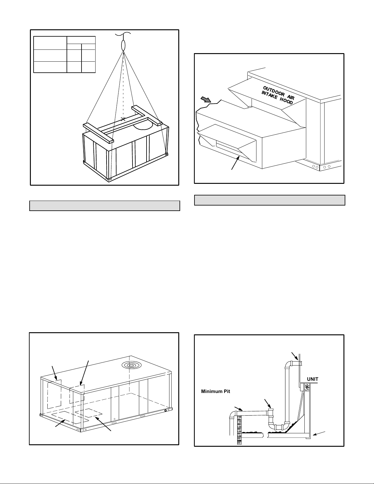
Rigging Unit For Lifting
Rig unit for lifting by attaching four cables to holes in unit
base rail. See figure 2.
1- Detach wooden base protection before rigging.
2- Remove all six base protection brackets before
setting unit.
3- Connect rigging to the unit base using both holes in
each corner.
4- All panels must be in place for rigging.
5- Place field‐provided H‐style pick in place just above
top edge of unit. Frame must be of adequate
strength and length. (H-style pick prevents damage
to unit.)
Page 5
Unit
LG
LC
*Maximum weight with all available
factory-installed accessories.
LIFTING POINT SHOULD
BE DIRECTLY ABOVE
CENTER OF GRAVITY
*Weight
Lbs. Kg.
435
960
423
933
IMPORTANT - ALL
PANELS MUST
BE IN PLACE
FOR RIGGING.
5- Install return air duct beneath outdoor air intake. See
figure 4. Install barometric relief damper in lower
hood and install in ductwork as shown in figure 4.
HORIZONTAL RETURN AIR DUCTWORK
WITH ECONOMIZER
UNITUNIT
HORIZONTAL
RETURN AIR
DUCT
CAUTION - Do
not walk on unit.
FIGURE 2
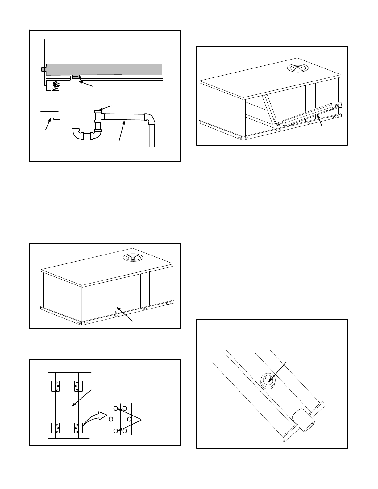
Horizontal Air Discharge
Unit is shipped with panels covering the horizontal supply
and return air openings. Remove horizontal covers and
place over downflow openings for horizontal air discharge.
See figure 3. Secure in place with sheet metal screws.
Units Equipped With An Optional Economizer
1- Remove the horizontal supply air cover and position
over the downflow supply air opening. Secure with
sheet metal screws.
2- Leave the horizontal return air cover in place.
3- Locate the separately ordered horizontal air
discharge kit. Place the kit panel over the downflow
return air opening.
4- Remove and retain the barometric relief dampers and
lower hood.
UNIT SUPPLY AND RETURN AIR OPENINGS
HORIZONTAL
HORIZONTAL
RETURN AIR
OPENING
SUPPLY AIR
OPENING
INSTALL BAROMETRIC RELIEF DAMPERS
AND HOOD IN RETURN AIR DUCT
FIGURE 4
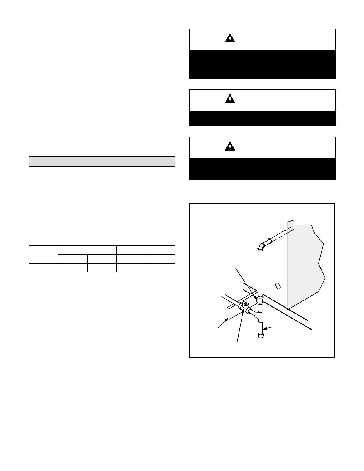
Condensate Drains
Make drain connection to the drain coupling provided on
unit. Older model units have a 3/4” N.P.T. coupling and
newer model units have a 1” N.P.T. coupling.
Note - The drain pan is made with a glass reinforced
engineered plastic capable of withstanding typical joint
torque but can be damaged with excessive force. Tighten
pipe nipple hand tight and turn an additional quarter turn.
A trap must be installed between drain connection and an
open vent for proper condensate removal. See figure 5 or
6. It is sometimes acceptable to drain condensate onto
the roof or grade; however, a tee should be fitted to the
trap to direct condensate downward. The condensate line
must be vented. Check local codes concerning
condensate disposal. Refer to pages 1 and 2 for
condensate drain location.
CONDENSATE SIDE DRAIN CONNECTION
CAULK AROUND CONDENSATE COUPLING
NOTE - Allow clearance to
open doors when installing
condensate piping.
Minimum Pitch
1” (25 mm) per
10' (3 m) of line
OPEN VENT
UNIT
DOWNFLOW
RETURN AIR
OPENING
DOWNFLOW
SUPPLY AIR
FIGURE 3
MOUNTING
FRAME
OPENING
FIGURE 5
Page 6
LGH/LCH036, 048, 060, 072
CONDENSATE BOTTOM DRAIN CONNECTION
2- Lift the front edge of the drain pan and slide pan out
of unit. See figure 9.
UNIT
DRAIN PAN
CAULK AROUND
CONDENSATE COUPLING
OPEN VENT
MOUNTING
FRAME
Minimum Pitch
1” (25 mm) per 10'
(3 m) of line
FIGURE 6
Units are shipped with the drain coupling facing the front
of the unit. Condensate can be drained from the back or
bottom of the unit with the following modifications. The
unit can be installed in either downflow or horizontal air
discharge regardless of condensate drain location.
Rear Drain Connection
1- Remove the condensate drain mullion. See figure 7.
Remove the two panels on each side of the mullion.
REMOVE DRAIN PAN
DRAIN PAN
FIGURE 9
3- Make sure the cap over the unit bottom drain hole is
secure.
4- Rotate the drain pan until the downward slope is
toward the back of the unit. Slide the drain pan back
into the unit. Be careful not to dislodge the cap over
the bottom drain hole.
5- From the back side of the unit, pull the drain pan
coupling through the rear condensate opening.
6- Replace the condensate drain mullion.
Bottom Drain Connection
CONDENSATE
DRAIN MULLION
FIGURE 7
Two hinge screws must be removed in addition to the
mullion screws. See figure 8.
UNITS WITH HINGED PANELS
CONDENSATE
DRAIN MULLION
REMOVE
TWO
SCREWS
FIGURE 8
1- Remove the condensate drain mullion. See figure 7.
2- Lift the front edge of the drain pan and slide pan out
of unit. See figure 9.
3- Turn the drain pan upside down and drill a pilot hole
through the bottom of the drain pan in the center of
the coupling. See figure 10.
BOTTOM CONDENSATE DRAIN
CAUTION: Be careful not to
damage the coupling threads
when drilling the hole.
After drilling the pilot
hole, drill a 7/8” hole from
the inside of the pan.
DRILL A PILOT
HOLE IN CENTER
OF COUPLING
FIGURE 10
LGH/LCH036, 048, 060, 072
Page 7
®
4- From the inside of the pan, use a Vari-Bit
bit to
enlarge the hole to 7/8”. Do not damage coupling
threads.
5- Remove the cap over the unit bottom drain hole.
6- Slide the drain pan back into the unit.
7- From the back side of the unit, pull the drain pan
coupling through the rear condensate opening.
8- From the front side of the unit, move the drain pan
until the bottom coupling settles into the unit bottom
drain opening. Once in place, check to make sure the
coupling is still positioned through the rear
condensate drain hole.
9- Use a field-provided 3/4” plug to seal side drain
connection.
10- Replace the condensate drain mullion.
CAUTION
If a flexible gas connector is required or allowed by
the authority that has jurisdiction, black iron pipe
shall be installed at the gas valve and extend out
side the furnace cabinet.
WARNING
Do not exceed 600 in-lbs (50 ft.-lbs) torque when at
taching the gas piping to the gas valve.
IMPORTANT
Connect Gas Piping (Gas Units)
Before connecting field-provided piping, check with gas
company or authorities having jurisdiction for local code
requirements. When installing gas supply piping, length
of run from gas meter must be considered in determining
pipe size for 0.5” w.c. (.12kPa) maximum pressure drop.
Do not use supply pipe smaller than unit gas connection.
Operating pressures at the unit gas connection must be
as shown in table 1.
TABLE 1
OPERATING PRESSURE AT GAS CONNECTION “w.c.
Natural Gas LP / Propane Gas
Min. Max. Min. Max.
036-072 4.5 10.5 11 13
When making piping connections a drip leg should be
installed on vertical pipe runs to serve as a trap for
sediment or condensate. A 1/8” N.P.T. plugged tap is
located on gas valve for test gauge connection. Refer to
Heating Start-Up section for tap location. Install a ground
joint union between the gas control manifold and the
main manual shut-off valve. See figure 11 for gas supply
piping entering outside the unit. Figure 12 shows
complete bottom gas entry piping.
Compounds used on threaded joints of gas piping shall be
resistant to the action of liquified petroleum gases.
Do not use Teflon® tape to seal gas piping. Use a
moderate amount of pipe compound on the gas pipe only.
Make sure the two end threads are bare.
Compounds used on threaded joints of gas piping
must be resistant to the actions of liquified petro
leum gases.
OUTSIDE OF UNIT GAS PIPE CONNECTION
TO GAS
VALV E
GROUND
JOINT UNION
TO GAS
SUPPLY
GAS PIPING
SUPPORT
MANUAL MAIN
SHUT-OFF VALVE
DRIP LEG
(REFER TO
LOCAL CODES)
FIGURE 11
Page 8
LGH/LCH036, 048, 060, 072
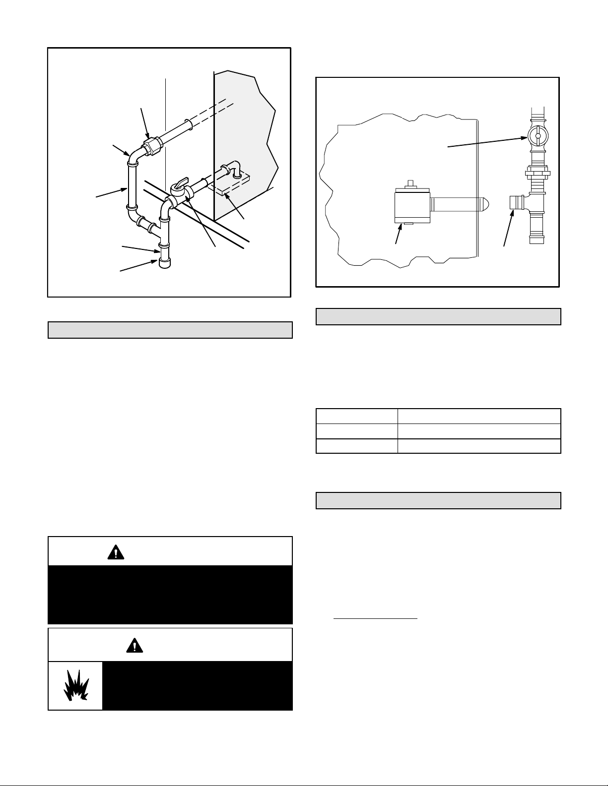
BOTTOM ENTRY GAS PIPING COMPLETED
power to unit. These devices should be properly labeled
by the installer.
GROUND
JOINT UNION
STREET
ELBOW
7” NIPPLE
2-1/2” NIPPLE
DRIP LEG
Grommets for both gas pipe openings are field provided.
TO GAS
VALV E
TO GAS
SUPPLY
MANUAL MAIN
SHUT-OFF VALVE
FIGURE 12
Pressure Test Gas Piping (Gas Units)
When pressure testing gas lines, the gas valve must
be disconnected and isolated. Gas valves can be
damaged if subjected to more than 0.5 psig (3.48kPa).
See figure 13.
NOTE-Codes may require that manual main shut-off
valve and union (furnished by installer) be installed in
gas line external to unit. Union must be of the ground
joint type.
PRESSURE TEST GAS LINE
MANUAL MAIN
SHUT-OFF VALVE
GAS VALVE
CAP
FIGURE 13
High Altitude Derate
Locate the high altitude conversion sticker in the unit
literature bag. Fill out the conversion sticker and affix next
to the unit nameplate.
Refer to table 2 for high altitude adjustments.
TABLE 2
HIGH ALTITUDE DERATE
Altitude Ft.* Gas Manifold Pressure
2000-4500 See Unit Nameplate
4500 And Above Derate 2% / 1000 Ft. Above Sea Level
After all connections have been made, check all piping
connections for gas leaks. Also check existing unit gas
connections up to the gas valve; loosening may occur
during installation. Use a leak detection solution or other
preferred means. Do not use matches candles or other
sources of ignition to check for gas leaks.
CAUTION
Some soaps used for leak detection are corrosive
to certain metals. Carefully rinse piping thoroughly
after leak test has been completed. Do not use
matches, candles, flame or othe sources of ignition
to check for gas leaks.
WARNING
Danger of explosion. Can cause injury
or product or property damage. Do not
use matches, candles, flame or other
sources of ignition to check for leaks.
NOTE-In case emergency shut down is required, turn off
the main manual shut-off valve and disconnect main
LGH/LCH036, 048, 060, 072
*Units installed at 0-2000 feet do not need to be modified.
NOTE ‐ This is the only permissible derate for these units.
Electrical Connections
POWER SUPPLY
Do not apply power or close disconnect switch until
installation is complete. Refer to start-up directions.
Refer closely to unit wiring diagram.
Refer to unit nameplate for minimum circuit ampacity
and maximum fuse size.
1- Units are factory-wired for 230,460,575 volt supply.
For 208V supply
cover from the 208V terminal on the control
transformer. Move the wire from the transformer
240V terminal to the 208V terminal. Place the
insulated terminal cover on the unused 240V
terminal.
2- Route power through the bottom power entry area
and connect to L1, L2, and L3 on the top of K1 in
control area above compressor. Secure power
wiring with factory-installed wire ties provided in
Page 9
, remove the insulated terminal

control box. Route power to TB2 on units equipped
with electric heat. Route power to S48 or CB10 If
unit is equipped with the optional disconnect
switch or circuit breaker. See unit wiring diagram.
3- Solar-Ready Units Only -
All solar-ready units are equipped with an S48 circuit
breaker and F54 solar fuse block. Connect power
wiring to the top of S48. Connect solar module wiring
to the pigtails provided on the bottom of F54. Solar
equipment must be specified for use with this unit.
CONTROL WIRING
CAUTION
Electrostatic discharge can affect electronic com
ponents. Take precautions during unit installation
and service to protect the electronic controls. Pre
cautions will help to avoid control exposure to elec
trostatic discharge by putting the unit, the control
and the technician at the same electrostatic poten
tial. Neutralize electrostatic charge by touching
hands and all tools on an unpainted unit surface,
such as the gas valve or blower deck, before per
forming any service procedure.
A-Thermostat Location
Room thermostat mounts vertically on a standard 2” X 4”
handy box or on any non-conductive flat surface.
Locate thermostat approximately 5 feet (1524mm)
above the floor in an area with good air circulation at
average temperature. Avoid locating the room
thermostat where it might be affected by:
-drafts or dead spots behind doors and in corners
-hot or cold air from ducts
-radiant heat from sun or appliances
-concealed pipes and chimneys
B-Control Wiring
The Unit Controller will operate the unit from a
thermostat or zone sensor based on the System Mode.
The default System Mode is the thermostat mode. Refer
to the Unit Controller Installation and Setup Guide to
change the System Mode. Use the menu navigation
arrows and select button; see Settings - Install.
Thermostat Mode
1- Route thermostat cable or wires from subbase to
control area above compressor (refer to unit
dimensions to locate bottom and side power entry).
IMPORTANT - Unless field thermostat wires are rated
for maximum unit voltage, they must be routed away
from line voltage wiring. Use wire ties located near the
lower left corner of the controls hat section to secure
thermostat cable.
Use18 AWG wire for all applications using remotely
installed electro-mechanical and electronic
thermostats.
2- Install thermostat assembly in accordance with
instructions provided with thermostat.
3- Connect thermostat wiring to Unit Controller on the
lower side of the controls hat section.
4- Wire as shown in figure 14 for electro-mechanical
and electronic thermostats. If using other
temperature control devices or energy management
systems see instructions and wiring diagram
provided by manufacturer.
IMPORTANT-Terminal connections at the wall plate or
subbase must be made securely. Loose control wire
connections may allow unit to operate but not with proper
response to room demand.
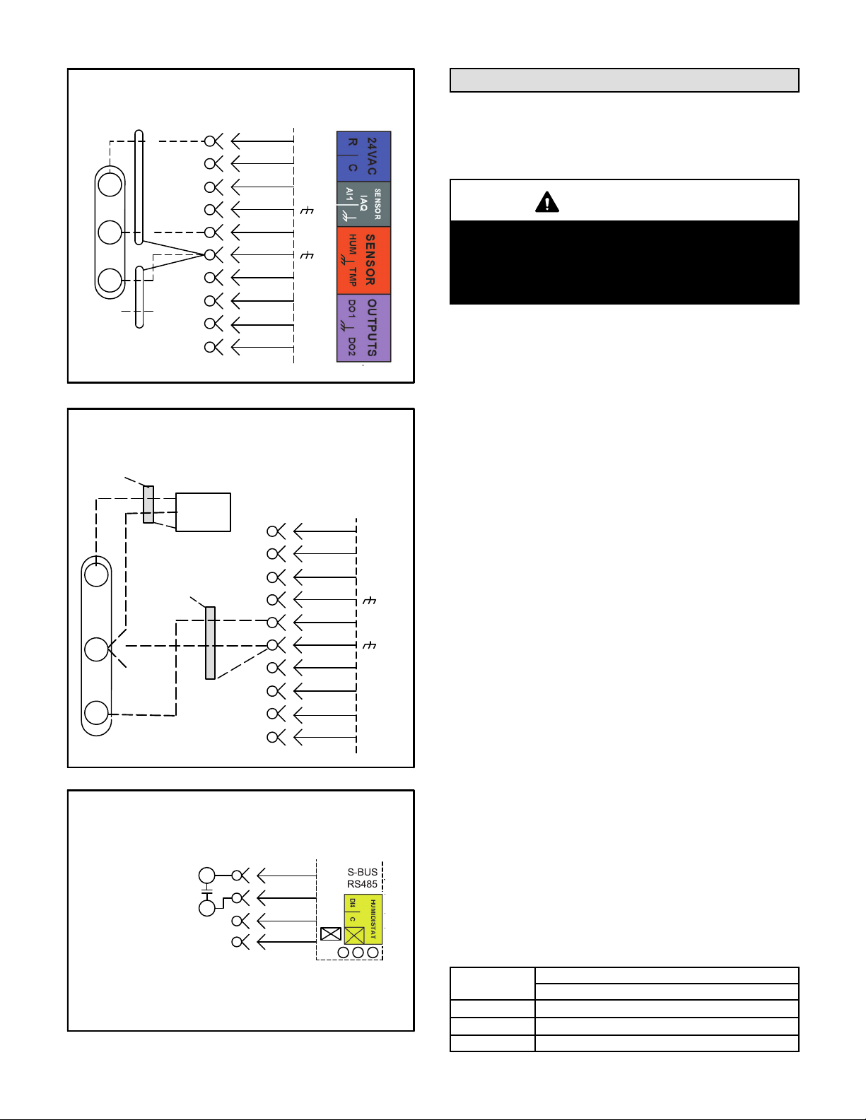
Zone Sensor Mode
The Unit Controller will operate heating and cooling
based on the Unit Controller internal setpoints and the
temperature from the A2 zone sensor. An optional
Network Control Panel (NCP) can also be used to provide
setpoints. A thermostat or return air sensor can be used
as a back-up mode. Make zone sensor wiring
connections as shown in figure 15.
Page 10
LGH/LCH036, 048, 060, 072
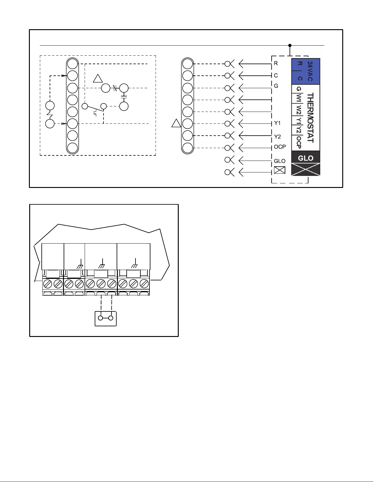
FIELD WIRING WITH ELECTRONIC AND ELECTRO-MECHANICAL THERMOSTATS
24 V POWER
TO M2 THERMOSTAT INPUTS
R
C
G
B
K55
A
TO PROVIDE SUPERMARKET REHEAT SCHEME
USE S86 DEHUMIDISTAT AND K55.
W1
W2
Y1
Y2
OCP
2
2
K55−1
S86
ALL OTHER THERMOSTAT
SIGNALS REMAIN CONNECTED
AS SHOWN ON THE RIGHT.
TO R
7
TO G
5
TO Y1
(Thermostat Mode)
R
C
G
W1
W2
Y1
2
Y2
OCP
FIGURE 14
J297A
B
C
10
P297
1
A55
P262
10
J262C
2
11
3
4
5
W1
W2
12
6
7
8
9
FIELD WIRING IN ZONE SENSOR MODE
(Zone Sensor Mode)
UNIT CONTROLLER
24VAC
RC
SENSOR
IAQ
AI1
SENSOR
HUM
TMP
OUTPUTS
D01
D02
J298
A2 SENSOR
FIGURE 15
C-Hot Gas Reheat Units Only -
1- Install humidity sensor in accordance with
instructions provided with sensor. A DDC input may
be used to initiate dehumidification instead of a
sensor.
2- Make wiring connections as shown in figure 14 for
Thermostat Mode or figure 15 for Zone Sensor
Mode. In addition, connect either a humidity
sensor or a dehumidification input. See figure 16
or 17 for humidity sensor wiring or figure 18 for
dehumidification input wiring.
Humidity Sensor Cable Applications:
Wire runs of 50 feet (mm) or less:
Use two separate shielded cables containing 20AWG
minimum, twisted pair conductors with overall shield.
Belden type 8762 or 88760 (plenum) or equivalent.
Connect both cable shield drain wires to TB1-7 as shown
in figure 16.
Wire runs of 150 feet (mm) or less:
Use two separate shielded cables containing 18AWG
minimum, twisted pair conductors with overall shield.
Belden type 8760 or 88760 (plenum) or equivalent.
Connect both cable shield drain wires to TB1-7 as shown
in figure 16.
Wire runs over 150 feet (mm):
Use a local, isolated 24VAC transformer such as Lennox
cat #18M13 (20VA minimum) to supply power to RH
sensor as shown in figure 17. Use two shielded cables
containing 20AWG minimum, twisted pair conductors
with overall shield. Belden type 8762 or 88760 (plenum)
or equivalent.
LGH/LCH036, 048, 060, 072
Page 11
FIELD WIRING REHEAT UNITS (Using A Humidity
Sensor With Less Than 150 Ft. Wire Runs)
P298
1
2
B
3
4
C
5
6
7
D
8
9
10
R
C
AI−1
HUM
TMP
DO−1
C
DO−2
DI−1
10
11
12
P262
J262B
5
6
A91
VIN
VO
GND
J298A
2
FIGURE 16
FIELD WIRING REHEAT UNITS (Using A Humidity
Sensor With More than 150 Ft. Wire Runs)
NOT
CONNECTED
A91
VIN
GND
VO
ISOLATED 24V
TRANSFORMER
DRAIN
NOT
CONNECTED
J298A
A55 UNIT
CONTROLLER
P298
1
2
B
3
4
C
5
6
7
D
8
9
10
R
C
AI-1
HUM
TMP
DO-1
C
DO-2
DI-1
FIGURE 17
FIELD WIRING REHEAT UNITS
(Using A Dehumidification Switch)
J299
R
DI−4
C
DEHUMIDIFICATION
SWITCH
Use 24 VAC (R) from any terminal
available on J299−2, −5, or −7.
7
8
9
10
FIGURE 18
Page 12
Blower Operation and Adjustments
Three-, four- and five-ton units are equipped with either
direct drive or multi-pole belt drive blowers. 6-ton units
are available with belt drive blowers only.
IMPORTANT
Three phase scroll compressors must be phased
sequentially for correct compressor and blower
rotation. Follow “COOLING START-UP” section of
installation instructions to ensure proper compres
sor and blower operation.
A-Blower Operation
Refer to the Unit Controller Installation and Setup Guide
to energize blower. Use the menu navigation arrows and
select button; see Service - Test.
B-Determining Unit CFM
1- The following measurements must be made with air
filters in place.
IMPORTANT - On units equipped with direct drive
blowers, determine and adjust high speed CFM before
low speed CFM. Low speed CFM should be adjusted to
2/3 of high speed CFM. A low speed adjustment less than
2/3 of high speed will improve humidity removal; refer to
product data for more information.
2- With all access panels in place, measure static
pressure external to unit (from supply to return).
Blower performance data is based on static pressure
readings taken in locations shown in figure 19.
Note - Static pressure readings can vary if not taken
where shown.
3- Measure the indoor blower wheel RPM.
4- Referring to Page 16 through Page 26, use static
pressure and RPM readings to determine unit CFM.
Use Page 27 when installing units with any of the
options or accessories listed. Refer to table 3 for
minimum airflow when electric heat is installed.
TABLE 3
MINIMUM AIRFLOW-LC UNITS WITH ELECTRIC HEAT
(BELT DRIVE)
Kw
LCH036HE
LCH048HE
LCH060HE
Downflow & Horizontal Airflow
LGH/LCH036, 048, 060, 072
CFM
1080
1280
1600
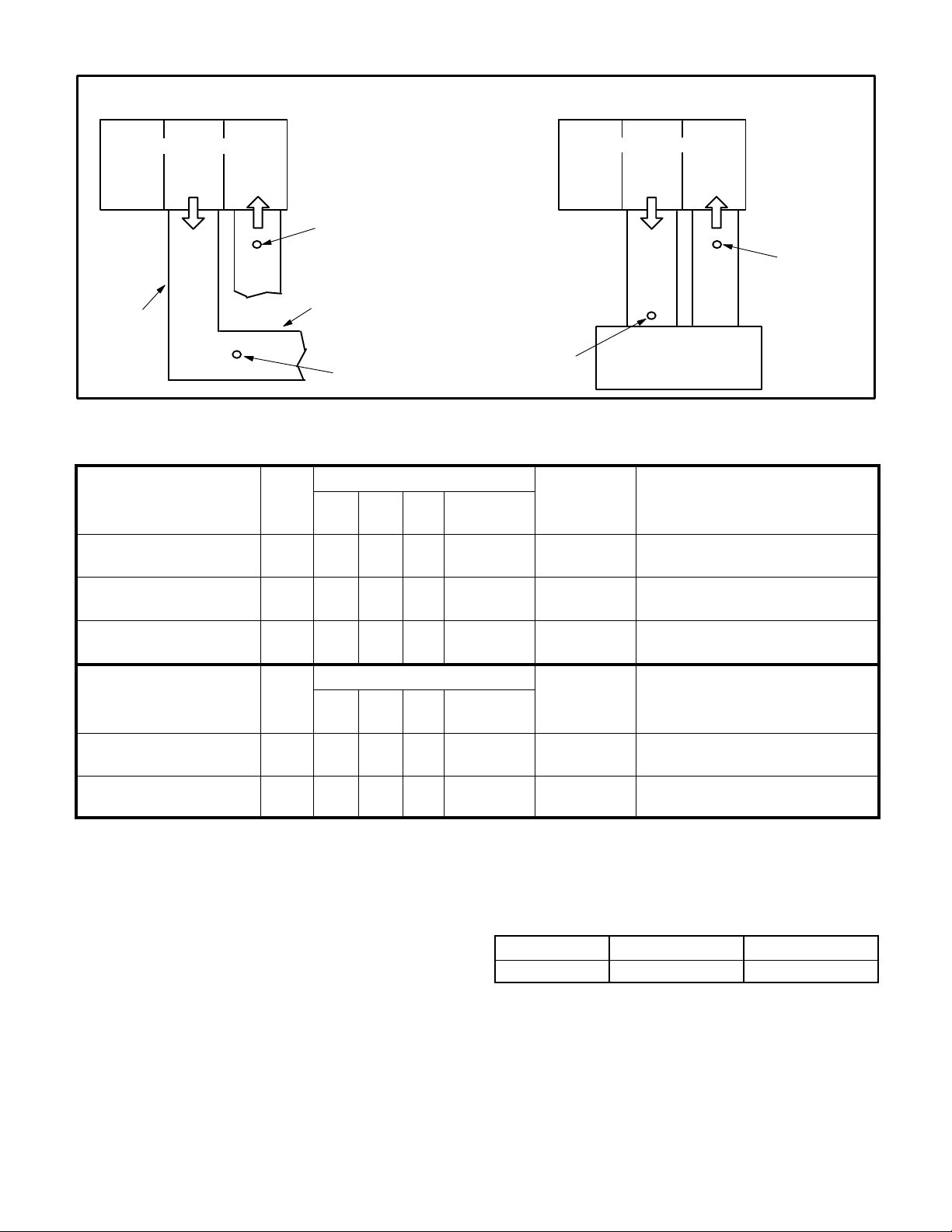
LOCATION OF STATIC PRESSURE READINGS
INSTALLATIONS WITH DUCTWORK
INSTALLATIONS WITH CEILING DIFFUSERS
ROOFTOP UNIT
RETURN AIR
READING LOCATION
SUPPLY
MAIN
DUCT RUN
RE
TURN
FIRST BRANCH
OFF OF MAIN RUN
SUPPLY AIR
READING
LOCATION
ECTO SETTINGS
Unit Controller “SET
TINGS-CONTROL-MSAV”
Menu
SMOKE SPEED 0.02 55 80 59
HIGH SPEED 0.04 55 80 59
ECTO
LGH/LCH Unit Factory Settings
036
048
060
H4E
H4E
H4E
SUPPLY AIR
LOCATION
FIGURE 19
TABLE 4
036-060
S4T
Not Applica
ble
Not Applica
ble
ROOFTOP UNIT
SUPPLY
READING
Field Setting Description
DIFFUSER
% torque for indoor blower smoke
speed.
% torque for indoor blower high
speed.
RE
TURN
RETURN AIR
READING
LOCATION
060
H4E
Not Applica
ble
036-060
S4T
Not Applica
ble
Field Setting Description
LOW SPEED 0.05 28 40 36
Unit Controller “SET
TINGS-SETPOINTSDAMPER” Menu
MIN OCP BLOWER LOW 0.09 15 15 15
MIN OCP BLOWER HIGH 5.24 10 10 10 10
Installer: Circle applicable unit model number and record any ECTO changes under “Field Setting” column. Settings need to be recorded by
installer for use when unit controller is replaced or reprogrammed. Refer to unit controller guide “Setting” menu path or use optional software to
change settings.
ECTO
LGH/LCH Unit Factory Settings
036
048
H4E
H4E
C-Adjusting Unit CFM - Direct Drive Blowers
The supply CFM can be adjusted by changing Unit
Controller settings; see Settings - Control - MSAV menu.
Refer to table 4. Adjustments can also be made by using
optional software. Record any CFM changes on the
MINIMUM AND MAXIMUM PULLEY ADJUSTMENT
Belt Min. Turns Open Maxi. Turns Open
A Section No minimum 5
% torque for indoor blower low
speed.
Damper minimum position during
low indoor blower.
Damper minimum position during
high indoor blower.
TABLE 5
ECTO Settings label located on the inside of the
compressor access panel.
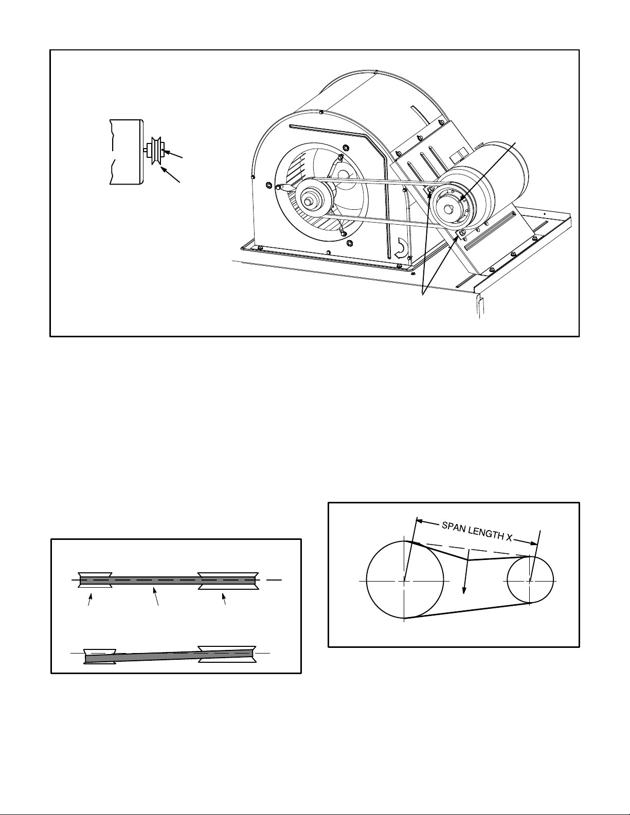
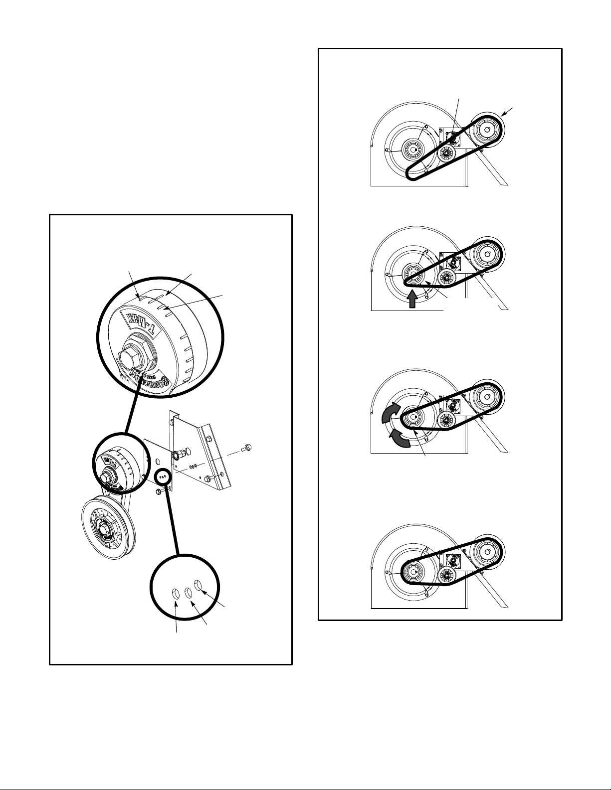
D-Adjusting Unit CFM - Belt Drive Blowers
The blower RPM can be adjusted at the motor pulley.
Loosen Allen screw and turn adjustable pulley clockwise
to increase CFM. Turn counterclockwise to decrease
CFM. See figure 20. Do not exceed minimum and
maximum number of pulley turns as shown in table 5.
E-Blower Belt Adjustment - Belt Drive
Maximum life and wear can be obtained from belts only
if proper pulley alignment and belt tension are
maintained. Tension new belts after a 24-48 hour
period of operation. This will allow belt to stretch and
seat grooves. Make sure blower and motor pulley are
aligned as shown in figure 21.
Page 13
LGH/LCH036, 048, 060, 072
TO INCREASE CFM
LOOSEN ALLEN SCREW &
TURN PULLEY CLOCKWISE
BLOWER ASSEMBLY
TO DECREASE CFM
TURN PULLEY
COUNTERCLOCKWISE
SIDE VIEW
MOTOR
TO INCREASE BELT TENSION
1-Loosen four bolts securing motor base to mounting
frame.
2-Slide the motor downward to tighten the belt.
3-Tighten four bolts on motor base.
ALLEN
SCREW
PULLEY
FIGURE 20
1- Loosen four bolts securing motor base to mounting
frame. See figure 20.
2- To increase belt tension -
Slide blower motor downward to tighten the belt. This
increases the distance between the blower motor and
the blower housing.
3- To loosen belt tension -
Slide blower motor upward to loosen the belt. This
decreases the distance between the blower motor
and the blower housing.
LOOSEN ALLEN
SCREW TO
ADJUST CFM
LOOSEN FOUR BOLTS AND
SLIDE BLOWER MOTOR
DOWNWARD TO TIGHTEN BELT
3- Remove the screw from the back side of the bracket.
4- Move the tensioner to the appropriate adjustment
hole and reinstall screw.
5- Replace bracket.
6- Replace blower belt. See figure 24.
G-Check Belt Tension
Overtensioning belts shortens belt and bearing life.
Check belt tension as follows:
1- Measure span length X. See figure 22.
4- Tighten four bolts securing motor base to the
mounting frame.
PULLEY ALIGNMENT
ALIGNED
MOTOR
PULLEY
BELT
NOT ALIGNED
BLOWER
PULLEY
FIGURE 21
F-Blower Belt Adjustment - Units Equipped With An
Optional Belt Tensioner
1- Remove blower belt.
2- Remove bracket from blower housing. See figure 23.
MEASURE BELT TENSION
FORCE
DEFLECTION 1/64” PER INCH OF SPAN
OR 1.5mm PER 100mm OF SPAN
FIGURE 22
2- Apply perpendicular force to center of span (X) with
enough pressure to deflect belt 1/64” for every inch
of span length or 1.5mm per 100mm of span length.
Example: Deflection distance of a 40” span would be
40/64” or 5/8”.
Example: Deflection distance of a 400mm span
would be 6mm.
Page 14
LGH/LCH036, 048, 060, 072
3- Measure belt deflection force. For a used belt, the
deflection force should be 5 lbs. (35kPa). A new belt
deflection force should be 7 lbs. (48kPa).
A force below these values indicates an
undertensioned belt. A force above these values
indicates an overtensioned belt.
H-Field-Furnished Blower Drives
For field-furnished blower drives, use page 19 through 26
to determine BHP and RPM required. Reference Page 27
to determine the drive kit number. Reference table 6 for
manufacturer's drive numbers.
INSTALL BELT
TENSIONER
1
DRIVER
PULLEY
ADJUST BELT TENSIONER
MAXIMUM
TENSION
INDICATOR SHOULD BE
BETWEEN MINIMUM AND
MAXIMUM TENSION LINES
BRACKET
MINIMUM
TENSION
2
DRIVEN
PULLEY
3
ROTATE DRIVEN
PULLEY TO SEAT BELT
TENSIONER
FACTORY-SET
POSITION
FIGURE 23
LGH/LCH036, 048, 060, 072
TIGHTEST
POSITION
TIGHTER
BELT
POSITION
4
BELT
FIGURE 24
Page 15

189 1373 495 1207 1494 558 1225
166 434 1222 1265 481 1234 1364 527 1246
70% 80% 90% 100%
Percentage of Total Motor Torque
Cfm Watts RPM Cfm Watts RPM Cfm Watts RPM Cfm Watts RPM
70% 80% 90% 100%
Cfm Watts RPM Cfm Watts RPM Cfm Watts RPM Cfm Watts RPM
Percentage of Total Motor Torque
BLOWER DATA - DIRECT DRIVE - 3 TON
BLOWER TABLE INCLUDES RESISTANCE FOR BASE UNIT ONLY WITH DRY INDOOR COIL AND AIR FILTERS IN PLACE.FOR ALL UNITS ADD:
1 - Any factory installed options air resistance (heat section, economizer, etc.).
20% 30% 40% 50% 60%
Cfm Watts RPM Cfm Watts RPM Cfm Watts RPM Cfm Watts RPM Cfm Watts RPM
Press.
in. w.g.
0 796 39 407 975 69 451 1154 98 494 1298 140 567 1442 181 639 1570 236 692 1697 292 744 1807 357 785 1917 422 825
2 - Any eld installed accessories air resistance (duct resistance, diffuser, etc.).
See page 27 for wet coil and options/accessory air resistance data.
Static
DOWNFLOW
External
0.1 719 44 482 915 76 523 1110 108 564 1257 151 626 1404 193 687 1537 248 733 1670 304 779 1784 369 815 1898 433 850
0.2 663 49 538 864 83 585 1064 117 633 1220 160 679 1375 203 725 1508 259 770 1641 316 815 1754 384 853 1866 452 891
0.3 593 55 607 806 91 651 1018 126 695 1174 171 737 1330 216 780 1471 272 815 1612 328 850 1724 398 890 1835 469 930
0.4 527 60 665 749 97 708 971 135 751 1136 180 783 1300 225 815 1435 285 858 1569 344 900 1689 413 930 1809 481 959
0.5 460 65 722 692 104 761 924 143 801 1090 190 833 1256 238 866 1398 296 899 1540 355 932 1662 424 960 1784 493 988
0.6 - - - - - - - - - - - - - - - - - - 855 154 864 1033 202 889 1211 250 914 1361 308 939 1511 365 963 1629 437 995 1746 508 1028
0.7 - - - - - - - - - - - - - - - - - - 808 161 898 995 209 922 1181 258 946 1325 319 976 1468 379 1007 1588 450 1036 1708 522 1065
0.8 - - - - - - - - - - - - - - - - - - 743 170 942 940 220 966 1137 269 991 1281 331 1020 1425 392 1049 1548 463 1074 1670 533 1100
0.9 - - - - - - - - - - - - - - - - - - 676 178 979 884 229 1006 1092 280 1033 1237 342 1061 1381 404 1088 1513 472 1105 1645 539 1121
1.0 - - - - - - - - - - - - - - - - - - 605 187 1011 819 240 1049 1032 294 1087 1192 353 1100 1352 4 11 1112 1474 480 1137 1595 549 1161
1.1 - - - - - - - - - - - - - - - - - - - - - - - - - - - - - - - - - - - - 988 304 1124 1142 364 1141 1295 424 1158 1420 490 1177 1544 555 1195
1.2 - - - - - - - - - - - - - - - - - - - - - - - - - - - - - - - - - - - - - - - - - - - - - - - - - - - - - - 1251 433 1
Page 16
HORIZONTAL
20% 30% 40% 50% 60%
Static
Press.
External
Cfm Watts RPM Cfm Watts RPM Cfm Watts RPM Cfm Watts RPM Cfm Watts RPM
in. w.g.
0 807 44 372 982 65 431 1157 86 490 1299 126 546 1441 167 602 1565 214 647 1688 262 692 1795 328 734 1901 393 776
0.1 708 50 468 906 77 513 1103 104 559 1247 143 612 1391 183 666 1522 231 704 1652 280 742 1766 346 779 1879 413 815
0.2 634 56 541 841 88 583 1048 120 625 1206 156 663 1363 192 701 1491 243 742 1619 294 783 1731 361 820 1843 429 857
0.3 523 63 648 759 98 669 994 134 690 1150 171 729 1306 209 769 1446 258 796 1585 307 823 1696 376 860 1807 444 896
0.4 437 69 732 688 107 742 939 146 752 1101 183 785 1263 221 818 1399 273 849 1535 326 881 1653 392 908 1771 458 935
0.5 344 75 823 615 11 6 817 885 156 812 1053 194 838 1220 232 865 1361 285 892 1502 339 918 1614 406 949 1725 473 980
0.6 - - - - - - - - - - - - - - - - - - 817 167 883 990 207 905 1162 246 927 1307 301 949 1451 356 971 1570 420 993 1689 484 1014
0.7 - - - - - - - - - - - - - - - - - - 762 174 938 941 215 954 111 9 256 971 1269 312 988 1418 367 1005 1536 430 1026 1653 494 1047
0.8 - - - - - - - - - - - - - - - - - - 708 178 991 892 222 1002 1076 266 1013 1222 324 1034 1368 383 1054 1484 444 1073 1599 506 1092
0.9 - - - - - - - - - - - - - - - - - - 645 182 1050 832 230 1059 1019 277 1068 1168 337 1084 1317 397 1100 1431 456 1117 1545 516 1134
1.0 - - - - - - - - - - - - - - - - - - 584 184 1105 780 235 1106 976 285 1107 1122 348 1125 1267 4 11 1144 1379 467 1158 1491 522 1172
1.1 - - - - - - - - - - - - - - - - - - - - - - - - - - - - - - - - - - - - 923 295 1155 1070 359 1169 1217 423 1184 1327 475 1195 1436 526 1207
1.2 - - - - - - - - - - - - - - - - - - - - - - - - - - - - - - - - - - - - - - - - - - - - - - - - - - - - - - 1

Percentage of Total Motor Torque
Percentage of Total Motor Torque
BLOWER DATA - DIRECT DRIVE - 4 TON
BLOWER TABLE INCLUDES RESISTANCE FOR BASE UNIT ONLY WITH DRY INDOOR COIL AND AIR FILTERS IN PLACE.FOR ALL UNITS ADD:
1 - Any factory installed options air resistance (heat section, economizer, etc.).
20% 30% 40% 50% 60% 70% 80% 90% 100%
Cfm Watts RPM Cfm Watts RPM Cfm Watts RPM Cfm Watts RPM Cfm Watts RPM Cfm Watts RPM Cfm Watts RPM Cfm Watts RPM Cfm Watts RPM
0 1048 80 507 1261 135 582 1473 190 657 1655 274 729 1836 359 801 1987 461 863 2137 563 924 2291 698 975 2445 832 1025
0.1 1000 88 560 1218 146 633 1436 204 706 1624 289 771 1812 374 836 1965 479 896 2118 583 956 2261 716 1004 2403 849 1052
0.2 944 97 624 1177 156 683 1409 214 743 1595 304 812 1781 393 881 1940 497 934 2098 602 986 2235 729 1032 2372 856 1077
0.3 906 104 666 1139 166 728 1372 228 790 1561 320 858 1750 412 925 1915 515 970 2079 619 1015 2210 741 1058 2341 863 1100
0.4 849 11 3 728 1093 177 783 1336 241 837 1531 333 897 1726 425 957 1889 532 1004 2052 639 1051 2177 754 1090 2302 869 1129
0.5 793 121 790 1047 188 837 1300 254 883 1501 346 935 1702 438 987 1864 548 1036 2026 657 1085 2145 766 1120 2263 874 1155
0.6 - - - - - - - - - - - - - - - - - - 1263 267 929 1467 361 978 1671 454 1027 1836 564 1071 2000 673 111 6 2116 775 1145 2232 876 1175
0.7 - - - - - - - - - - - - - - - - - - 1226 280 974 1433 375 1019 1639 470 1065 1807 578 1104 1974 686 1144 2080 782 1173 2186 878 1203
0.8 - - - - - - - - - - - - - - - - - - 1195 291 1012 1402 388 1057 1608 485 1101 1778 591 1135 1948 697 1169 2052 787 1195 2155 878 1220
0.9 - - - - - - - - - - - - - - - - - - 1162 304 1060 1367 401 1097 1572 498 1134 1741 603 1168 1909 708 1202 2009 792 1223 2109 875 1244
1.0 - - - - - - - - - - - - - - - - - - 1133 316 1104 1333 414 1136 1533 511 1167 1702 612 1198 1870 714 1229 1959 791 1251 2047 868 1272
1.1 - - - - - - - - - - - - - - - - - - - - - - - - - - - - - - - - - - - - 1490 524 1200 1654 618 1228 1817 713 1256 1909 786 1273 2000 859 1289
Static
Press.
2 - Any eld installed accessories air resistance (duct resistance, diffuser, etc.).
See page 27 for wet coil and options/accessory air resistance data.
DOWNFLOW
External
in. w.g.
1.2 - - - - - - - - - - - - - - - - - - - - - - - - - - - - - - - - - - - - - - - - - - - - - - - - - - - - - - 1765 701 1272 1844 771 1293 1923 840 1314
Page 17
HORIZONTAL
20% 30% 40% 50% 60% 70% 80% 90% 100%
Static
Press.
External
Cfm Watts RPM Cfm Watts RPM Cfm Watts RPM Cfm Watts RPM Cfm Watts RPM Cfm Watts RPM Cfm Watts RPM Cfm Watts RPM Cfm Watts RPM
in. w.g.
0 1025 80 472 1238 131 552 1450 182 632 1626 254 702 1802 326 771 1936 414 824 2071 502 878 2231 634 931 2391 767 983
0.1 978 85 546 1199 138 610 1420 191 675 1601 265 738 1781 339 801 1930 441 862 2079 544 923 2222 663 968 2365 783 1013
0.2 927 89 602 1157 145 661 1387 201 720 1568 279 783 1749 357 845 1906 458 897 2062 559 949 2205 679 993 2348 798 1038
0.3 851 98 684 1098 156 731 1344 214 777 1531 295 833 1717 375 888 1876 478 938 2035 581 988 2166 694 1030 2297 807 1072
0.4 801 105 738 1051 166 785 1300 227 832 1493 309 881 1685 392 930 1847 496 977 2009 600 1023 2128 707 1064 2247 813 1105
0.5 725 11 8 817 991 179 850 1256 239 883 1455 324 926 1653 408 970 1814 516 1019 1974 623 1068 2091 720 1099 2207 817 1130
0.6 - - - - - - - - - - - - - - - - - - 1212 251 931 1417 337 969 1621 423 1008 1784 531 1053 1947 638 1098 2057 729 1126 2166 820 1154
0.7 - - - - - - - - - - - - - - - - - - 1169 263 975 1380 350 1010 1590 437 1045 1756 544 1086 1921 651 1127 2014 736 1157 2106 821 1187
0.8 - - - - - - - - - - - - - - - - - - 1114 277 1027 1331 366 1059 1547 454 1091 1717 560 1126 1886 666 1161 1976 743 1184 2066 821 1207
0.9 - - - - - - - - - - - - - - - - - - 1062 290 1077 1283 380 1106 1504 470 1135 1669 575 1170 1833 680 1204 1919 749 1220 2005 817 1236
1.0 - - - - - - - - - - - - - - - - - - 1007 304 1127 1240 392 1147 1473 481 1166 1627 584 1202 1780 687 1238 1853 748 1253 1925 809 1269
1.1 - - - - - - - - - - - - - - - - - - - - - - - - - - - - - - - - - - - - 1429 497 1211 1569 590 1240 1709 683 1269 1787 741 1280 1864 799 1291
1.2 - - - - - - - - - - - - - - - - - - - - - - - - - - - - - - - - - - - - - - - - - - - - - - - - - - - - - - 1604 651 1284 1684 714 1303 1763 777 1321

175 2137 984 1202 2290 1124 1230
163 2165 993 1185 2336 1125 1206
Percentage of Total Motor Torque
20% 30% 40% 50% 60% 70% 80% 90% 100%
Cfm Watts RPM Cfm Watts RPM Cfm Watts RPM Cfm Watts RPM Cfm Watts RPM Cfm Watts RPM Cfm Watts RPM Cfm Watts RPM Cfm Watts RPM
Percentage of Total Motor Torque
20% 30% 40% 50% 60% 70% 80% 90% 100%
Cfm Watts RPM Cfm Watts RPM Cfm Watts RPM Cfm Watts RPM Cfm Watts RPM Cfm Watts RPM Cfm Watts RPM Cfm Watts RPM Cfm Watts RPM
BLOWER DATA - DIRECT DRIVE - 5 TON
BLOWER TABLE INCLUDES RESISTANCE FOR BASE UNIT ONLY WITH DRY INDOOR COIL AND AIR FILTERS IN PLACE.FOR ALL UNITS ADD:
0 1132 79 438 1353 146 524 1575 212 610 1765 300 670 1954 388 730 2126 513 796 2298 638 861 2445 792 913 2591 946 965
in. w.g.
0.1 1061 86 494 1305 155 568 1548 223 641 1743 315 702 1937 407 764 2110 531 823 2282 654 883 2426 808 935 2570 963 987
Static
Press.
1 - Any factory installed options air resistance (heat section, economizer, etc.).
2 - Any eld installed accessories air resistance (duct resistance, diffuser, etc.).
See page 27 for wet coil and options/accessory air resistance data.
External
DOWNFLOW
0.2 990 94 550 1253 165 614 1516 236 678 1716 330 735 1916 423 793 2088 549 851 2260 675 910 2405 827 959 2549 979 1009
0.3 920 102 606 1202 175 659 1484 248 713 1687 345 770 1890 442 828 2065 568 882 2239 694 937 2384 844 983 2528 994 1030
0.4 849 111 662 1151 185 705 1452 260 747 1658 360 804 1863 460 861 2041 586 911 2218 713 962 2363 861 1006 2508 1009 1050
0.5 779 121 718 1094 198 754 1410 275 790 1626 374 838 1842 473 886 2020 601 936 2197 730 987 2342 876 1028 2487 1023 1070
0.6 - - - - - - - - - - - - - - - - - - 1368 289 830 1589 390 876 1810 492 921 1993 619 966 2176 746 1010 2316 895 1054 2456 1043 1099
0.7 - - - - - - - - - - - - - - - - - - 1325 303 868 1552 406 911 1778 509 954 1966 635 993 2154 761 1033 2295 908 1075 2435 1055 111 7
0.8 - - - - - - - - - - - - - - - - - - 1261 321 920 1504 423 952 1746 524 984 1934 653 1024 2122 782 1064 2268 925 1100 2414 1067 1135
0.9 - - - - - - - - - - - - - - - - - - 1211 337 964 1462 437 988 1714 538 1012 1902 669 1053 2090 801 1094 2237 942 1127 2383 1084 1161
1.0 - - - - - - - - - - - - - - - - - - 1151 354 1013 1412 454 1029 1672 553 1045 1871 682 1078 2069 8 11 1112 2211 955 1149 2352 1099 1185
Page 18
1.1 - - - - - - - - - - - - - - - - - - - - - - - - - - - - - - - - - - - - 1629 566 1073 1828 698 1109 2027 830 1146 2174 971 1177 2321 1112 1208
1.2 - - - - - - - - - - - - - - - - - - - - - - - - - - - - - - - - - - - - - - - - - - - - - - - - - - - - - - 1984 844 1
External
HORIZONTAL
Static
Press.
in. w.g.
0 1127 82 426 1367 141 504 1607 200 582 1806 296 644 2005 391 706 2167 495 764 2328 599 822 2463 749 872 2598 899 922
0.1 1071 86 476 1326 148 543 1580 210 610 1781 311 675 1981 4 11 740 2145 516 795 2309 620 849 2456 775 898 2602 931 947
0.2 1010 91 529 1268 160 598 1525 229 668 1735 332 724 1945 434 781 2117 537 828 2289 640 875 2438 795 921 2587 949 967
0.3 930 100 597 1214 169 647 1497 239 696 1707 345 755 1917 452 814 2093 556 857 2269 660 900 2417 817 948 2565 975 995
0.4 869 109 646 1156 184 699 1442 258 751 1665 364 798 1888 469 845 2066 577 889 2243 685 933 2393 842 978 2543 998 1022
0.5 813 119 689 111 4 193 734 1414 267 778 1637 376 827 1860 485 876 2039 597 920 2217 709 963 2373 861 1002 2528 1013 1040
0.6 - - - - - - - - - - - - - - - - - - 1358 286 831 1595 394 868 1832 501 905 2012 616 949 2191 731 993 2349 882 1028 2506 1033 1064
0.7 - - - - - - - - - - - - - - - - - - 1330 296 857 1560 409 903 1789 523 949 1977 638 985 2164 753 1020 2324 902 1054 2484 1052 1088
0.8 - - - - - - - - - - - - - - - - - - 1275 315 908 1518 426 942 1761 536 977 1950 655 1011 2138 773 1046 2296 923 1081 2454 1073 1116
0.9 - - - - - - - - - - - - - - - - - - 1233 329 946 1483 439 975 1732 549 1004 1922 670 1037 2112 792 1071 2272 939 1104 2432 1087 1136
1.0 - - - - - - - - - - - - - - - - - - 1192 343 982 1441 455 1012 1690 567 1043 1881 692 1074 2072 818 1105 2237 960 1133 2402 1102 1161
1.1 - - - - - - - - - - - - - - - - - - - - - - - - - - - - - - - - - - - - 1662 578 1068 1854 706 1097 2046 833 1126 2206 975 1157 2365 111 7 1188
1.2 - - - - - - - - - - - - - - - - - - - - - - - - - - - - - - - - - - - - - - - - - - - - - - - - - - - - - - 1994 861 1

BLOWER DATA - BELT DRIVE - 3 TON
BLOWER TABLE INCLUDES RESISTANCE FOR BASE UNIT ONLY WITH DRY INDOOR COIL AND AIR FILTERS IN PLACE.
FOR ALL UNITS ADD:
1 - Any factory installed options air resistance (heat section, economizer, etc.).
2 - Any eld installed accessories air resistance (duct resistance, diffuser, etc.).
See page 27 for blower motors and drives and wet coil and options/accessory air resistance data.
DOWNFLOW
External Static (in.w.g.)
Air
Volume
(cfm)
700 453 0.07 523 0.11 596 0.14 679 0.17 762 0.18 828 0.21 878 0.24 927 0.26 979 0.29 1029 0.31
800 471 0.09 542 0.13 614 0.16 696 0.19 777 0.21 841 0.23 889 0.26 938 0.29 990 0.31 1042 0.34
900 493 0.11 563 0.15 634 0.19 715 0.21 793 0.23 854 0.26 902 0.29 950 0.32 1002 0.34 1054 0.36
1000 517 0.14 587 0.18 657 0.21 736 0.24 811 0.26 869 0.29 916 0.32 964 0.35 1015 0.37 1067 0.4
1100 544 0.17 613 0.21 683 0.24 759 0.27 831 0.3 886 0.32 931 0.36 978 0.38 1028 0.41 1078 0.43
1200 574 0.2 643 0.24 711 0.27 784 0.3 852 0.33 904 0.36 947 0.39 993 0.42 1042 0.45 1091 0.47
0.10 0.20 0.30 0.40 0.50 0.60 0.70 0.80 0.9 1.0
RPM BHP RPM BHP RPM BHP RPM BHP RPM BHP RPM BHP RPM BHP RPM BHP RPM BHP RPM BHP
1300 608 0.24 676 0.28 743 0.31 812 0.34 875 0.37 923 0.4 964 0.44 1010 0.46 1057 0.49 1104 0.51
1400 645 0.28 711 0.31 776 0.35 842 0.38 898 0.41 942 0.44 983 0.48 1028 0.51 1074 0.53 1120 0.56
External Static (in.w.g.)
Air
Volume
(cfm)
700 1078 0.33 1124 0.36 - - - - - - - - - - - - - - - - - - - - - - - - - - - - - - - - - - - - - - - - - - - - - - - -
800 1091 0.36 1137 0.39 1180 0.41 1221 0.44 1260 0.47 - - - - - - - - - - - - - - - - - - - - - - - - - - - - - -
900 1105 0.39 1150 0.42 1192 0.45 1232 0.47 1270 0.5 1307 0.53 1345 0.56 1382 0.59 1420 0.62 - - - - - -
1000 1117 0.42 1162 0.45 1203 0.48 1242 0.51 1279 0.54 1316 0.57 1353 0.6 1390 0.63 1427 0.66 1465 0.7
1100 1126 0.46 1171 0.49 1212 0.52 1251 0.56 1288 0.59 1325 0.62 1361 0.65 1397 0.68 1433 0.71 1470 0.75
1200 1137 0.5 1180 0.54 1222 0.57 1260 0.6 1298 0.64 1334 0.67 1369 0.7 1404 0.73 1440 0.77 1477 0.8
1300 1149 0.55 1191 0.58 1232 0.62 1270 0.65 1307 0.69 1343 0.72 1378 0.76 1413 0.79 1449 0.82 1486 0.86
1400 1163
1.1 1.2 1.3 1.4 1.5 1.6 1.7 1.8 1.9 2.0
RPM BHP RPM BHP RPM BHP RPM BHP RPM BHP RPM BHP RPM BHP RPM BHP RPM BHP RPM BHP
0.6 1204 0.63 1243 0.67 1281 0.71 1317 0.74 1353 0.78 1388 0.82 1423 0.85 1459 0.89 1496 0.92
Page 19

BLOWER DATA - BELT DRIVE - 3 TON
BLOWER TABLE INCLUDES RESISTANCE FOR BASE UNIT ONLY WITH DRY INDOOR COIL AND AIR FILTERS IN PLACE.
FOR ALL UNITS ADD:
1 - Any factory installed options air resistance (heat section, economizer, etc.).
2 - Any eld installed accessories air resistance (duct resistance, diffuser, etc.).
See page 27 for blower motors and drives and wet coil and options/accessory air resistance data.
HORIZONTAL
Air
Volume
(cfm)
700 440 0.07 510 0.1 585 0.12 657 0.14 726 0.17 793 0.2 856 0.23 915 0.25 967 0.28 1016 0.31
800 456 0.08 526 0.11 600 0.14 672 0.16 739 0.19 804 0.22 866 0.25 923 0.28 975 0.31 1025 0.34
900 474 0.1 544 0.13 617 0.16 688 0.18 754 0.21 818 0.24 877 0.27 932 0.3 984 0.33 1034 0.36
1000 495 0.12 565 0.15 637 0.18 707 0.21 771 0.23 832 0.27 889 0.3 943 0.33 993 0.36 1043 0.39
1100 518 0.14 588 0.18 659 0.21 727 0.23 789 0.26 848 0.3 903 0.33 954 0.37 1003 0.4 1052 0.43
1200 544 0.17 613 0.21 682 0.24 748 0.27 809 0.29 866 0.33 918 0.37 967 0.4 1014 0.43 1062 0.46
1300 572 0.21 640 0.24 707 0.27 771 0.3 830 0.33 884 0.37 934 0.41 981 0.44 1027 0.47 1073 0.5
1400 602 0.24 669 0.28 733 0.31 795 0.34 851 0.37 903 0.41 950 0.45 995 0.49 1040 0.52 1086 0.55
Air
Volume
(cfm)
0.10 0.20 0.30 0.40 0.50 0.60 0.70 0.80 0.9 1.0
RPM BHP RPM BHP RPM BHP RPM BHP RPM BHP RPM BHP RPM BHP RPM BHP RPM BHP RPM BHP
1.1 1.2 1.3 1.4 1.5 1.6 1.7 1.8 1.9 2.0
RPM BHP RPM BHP RPM BHP RPM BHP RPM BHP RPM BHP RPM BHP RPM BHP RPM BHP RPM BHP
External Static (in.w.g.)
External Static (in.w.g.)
700 1065 0.33 - - - - - - - - - - - - - - - - - - - - - - - - - - - - - - - - - - - - - - - - - - - - - - - - - - - - - -
800 1075 0.36 1122 0.39 1164 0.42 1203 0.45 1241 0.47 - - - - - - - - - - - - - - - - - - - - - - - - - - - - - -
900 1086 0.39 1133 0.42 1174 0.45 1213 0.48 1250 0.51 1286 0.54 1322 0.57 1357 0.6 1392 0.64 - - - - - -
1000 1094 0.43 1142 0.46 1183 0.49 1222 0.52 1259 0.55 1295 0.58 1330 0.62 1365 0.65 1400 0.68 1435 0.71
1100 1102 0.46 1148 0.49 1191 0.53 1230 0.56 1267 0.6 1303 0.63 1338 0.66 1373 0.69 1408 0.73 1444 0.76
1200 1110 0.5 1156 0.53 1198 0.57 1238 0.61 1275 0.64 1311 0.68 1346 0.71 1381 0.74 1416 0.78 1452 0.81
1300 1120 0.54 1164 0.58 1207 0.62 1246 0.65 1283 0.69 1319 0.73 1354 0.76 1389 0.79 1424 0.83 1460 0.86
175 0.63 1216 0.67 1255 0.7 1292 0.74 1327 0.78 1362 0.81 1397 0.84 1432 0.88 1468 0.91
1400 1131
0.59 1
Page 20

BLOWER DATA - BELT DRIVE - 4 TON
BLOWER TABLE INCLUDES RESISTANCE FOR BASE UNIT ONLY WITH DRY INDOOR COIL AND AIR FILTERS IN PLACE.
FOR ALL UNITS ADD:
1 - Any factory installed options air resistance (heat section, economizer, etc.).
2 - Any eld installed accessories air resistance (duct resistance, diffuser, etc.).
See page 27 for blower motors and drives and wet coil and options/accessory air resistance data.
DOWNFLOW
External Static (in.w.g.)
Air
Volume
(cfm)
900 502 0.12 573 0.15 644 0.19 725 0.22 802 0.24 861 0.26 908 0.29 957 0.32 1009 0.34 1061 0.37
1000 528 0.14 598 0.18 668 0.22 747 0.24 821 0.27 877 0.3 923 0.33 971 0.35 1022 0.38 1074 0.4
1100 557 0.17 626 0.21 695 0.25 772 0.28 841 0.3 894 0.33 939 0.36 986 0.39 1037 0.41 1087 0.44
1200 589 0.21 657 0.25 725 0.28 798 0.31 864 0.33 913 0.37 956 0.4 1003 0.43 1052 0.45 1100 0.48
1300 625 0.25 692 0.28 759 0.32 827 0.34 887 0.37 933 0.41 975 0.44 1021 0.47 1068 0.49 1115 0.52
1400 665 0.29 730 0.32 794 0.35 857 0.38 911 0.42 953 0.45 995 0.49 1040 0.52 1086 0.54 1131 0.57
1500 706 0.33 768 0.36 829 0.39 886 0.43 934 0.46 974 0.5 1015 0.54 1060 0.56 1105 0.59 1149 0.62
0.10 0.20 0.30 0.40 0.50 0.60 0.70 0.80 0.9 1.0
RPM BHP RPM BHP RPM BHP RPM BHP RPM BHP RPM BHP RPM BHP RPM BHP RPM BHP RPM BHP
1600 746 0.37 805 0.4 862 0.44 914 0.48 957 0.52 996 0.55 1037 0.59 1081 0.62 1126 0.64 1167 0.68
1700 784 0.42 840 0.45 893 0.49 940 0.53 980 0.57 1019 0.61 1060 0.64 1104 0.67 1147 0.7 1187 0.74
1800 821 0.47 874 0.51 923 0.55 967 0.59 1006 0.63 1044 0.67 1085 0.7 1128 0.73 1170 0.77 1208 0.82
1900 857 0.53 906 0.57 952 0.62 994 0.66 1032 0.7 1071 0.73 111 2 0.76 1154 0.8 1194 0.85 1230 0.9
External Static (in.w.g.)
Air
Volume
(cfm)
900 1111 0.39 1156 0.42 1197 0.45 1236 0.48 1275 0.51 1312 0.54 1349 0.56 1387 0.59 1424 0.62 - - - - - -
1000 1124 0.43 1168 0.46 1209 0.49 1247 0.52 1285 0.55 1322 0.58 1358 0.61 1395 0.64 1432 0.67 1470 0.7
1100 1134 0.47 1178 0.5 1219 0.53 1258 0.56 1295 0.6 1331 0.63 1367 0.66 1403 0.69 1439 0.72 1477 0.75
1200 1146 0.51 1189 0.54 1230 0.58 1268 0.61 1305 0.65 1341 0.68 1376 0.71 1411 0.74 1447 0.77 1485 0.81
1300 1159
1400 1
1500 1189 0.66 1228 0.7 1266 0.74 1303 0.78 1339 0.81 1374 0.85 1409 0.89 1445 0.92 1481 0.96 1519 1
1600 1206 0.72 1244 0.76 1281 0.8 1317 0.84 1353 0.88 1388 0.92 1423 0.96 1459 1 1496 1.04 1535 1.08
1.1 1.2 1.3 1.4 1.5 1.6 1.7 1.8 1.9 2.0
RPM BHP RPM BHP RPM BHP RPM BHP RPM BHP RPM BHP RPM BHP RPM BHP RPM BHP RPM BHP
0.55 1201 0.59 1241 0.63 1279 0.66 1315 0.7 1351 0.73 1386 0.77 1421 0.8 1457 0.83 1495 0.87
173 0.61 1214 0.64 1253 0.68 1290 0.72 1327 0.75 1362 0.79 1397 0.82 1432 0.86 1468 0.89 1506 0.93
1700 1224 0.79 1261 0.83 1298 0.87 1334 0.91 1369 0.95 1404 0.99 1440 1.03 1476 1.07 1513 1.12 1552 1.16
1800 1244 0.86 1280 0.91 1316 0.95 1352 0.99 1387 1.03 1422 1.07 1457 1.11 1494 1.16 1532 1.2 1570 1.24
1900 1265 0.95 1301 1 1336 1.04 1371 1.08 1406 1.12 1441 1.16 1477 1.2 1515 1.24 1553 1.29 1592 1.33
Page 21

BLOWER DATA - BELT DRIVE - 4 TON
BLOWER TABLE INCLUDES RESISTANCE FOR BASE UNIT ONLY WITH DRY INDOOR COIL AND AIR FILTERS IN PLACE.
FOR ALL UNITS ADD:
1 - Any factory installed options air resistance (heat section, economizer, etc.).
2 - Any eld installed accessories air resistance (duct resistance, diffuser, etc.).
See page 27 for blower motors and drives and wet coil and options/accessory air resistance data.
HORIZONTAL
External Static (in.w.g.)
Air
Volume
(cfm)
900 483 0.1 554 0.13 627 0.16 699 0.19 765 0.22 826 0.24 882 0.27 935 0.3 986 0.33 1039 0.36
1000 505 0.12 576 0.16 648 0.19 719 0.21 784 0.24 842 0.27 896 0.3 947 0.33 998 0.37 1050 0.4
1100 530 0.15 601 0.18 671 0.21 741 0.24 804 0.27 860 0.3 912 0.34 961 0.37 1010 0.4 1060 0.43
1200 558 0.18 627 0.22 696 0.25 764 0.28 824 0.3 878 0.34 928 0.37 975 0.41 1023 0.44 1072 0.47
1300 588 0.22 656 0.25 723 0.28 788 0.31 846 0.34 897 0.38 945 0.42 990 0.45 1037 0.48 1084 0.51
1400 621 0.25 687 0.29 752 0.32 814 0.35 868 0.38 916 0.42 962 0.46 1006 0.5 1052 0.53 1098 0.56
1500 655 0.29 719 0.33 781 0.36 839 0.39 890 0.43 936 0.47 979 0.51 1023 0.55 1068 0.58 1113 0.61
0.10 0.20 0.30 0.40 0.50 0.60 0.70 0.80 0.9 1.0
RPM BHP RPM BHP RPM BHP RPM BHP RPM BHP RPM BHP RPM BHP RPM BHP RPM BHP RPM BHP
1600 690 0.33 751 0.37 810 0.4 865 0.44 912 0.48 955 0.52 997 0.56 1041 0.6 1086 0.63 1129 0.66
1700 725 0.38 784 0.41 839 0.45 891 0.49 935 0.53 975 0.58 1017 0.62 1060 0.65 1104 0.68 1147 0.72
1800 761 0.42 816 0.46 868 0.5 916 0.55 957 0.59 997 0.64 1038 0.68 1081 0.71 1124 0.74 1165 0.79
1900 795 0.48 848 0.52 897 0.56 942 0.61 981 0.66 1020 0.7 1060 0.74 1103 0.77 1145 0.81 1183 0.85
External Static (in.w.g.)
Air
Volume
(cfm)
900 1091 0.4 1138 0.43 1180 0.46 1220 0.49 1257 0.53 1293 0.56 1329 0.59 1364 0.62 1400 0.65 1435 0.69
1000 1101 0.43 1149 0.46 1190 0.5 1229 0.53 1266 0.57 1302 0.6 1338 0.63 1373 0.66 1408 0.7 1444 0.73
1100 1110 0.46 1156 0.5 1199 0.54 1238 0.57 1275 0.61 1311 0.64 1346 0.67 1381 0.71 1416 0.74 1452 0.78
1200 111 9 0.5 1165 0.54 1207 0.58 1247 0.62 1284 0.65 1319 0.69 1355 0.72 1389 0.75 1425 0.79 1460 0.82
1300 1130
1400 1143 0.6 1186 0.63 1226 0.67 1265 0.71 1302 0.75 1337 0.79 1372 0.82 1406 0.85 1441 0.89 1477 0.93
1500 1156 0.65 1198 0.69 1237 0.73 1275 0.77 1311 0.8 1346 0.84 1381 0.88 1415 0.91 1450 0.95 1486 0.98
1600 1171 0.7 1211 0.74 1249 0.78 1286 0.82 1321 0.86 1356 0.9 1390 0.93 1425 0.97 1460 1.01 1496 1.05
1.1 1.2 1.3 1.4 1.5 1.6 1.7 1.8 1.9 2.0
RPM BHP RPM BHP RPM BHP RPM BHP RPM BHP RPM BHP RPM BHP RPM BHP RPM BHP RPM BHP
175 0.59 1216 0.63 1255 0.66 1292 0.7 1328 0.74 1363 0.77 1398 0.8 1433 0.84 1469 0.87
0.55 1
1700 1186 0.76 1225 0.8 1262 0.84 1298 0.88 1333 0.92 1367 0.96 1401 1 1436 1.03 1471 1.07 1507 1.12
1800 1202 0.83 1240 0.87 1276 0.91 1311 0.95 1345 0.99 1380 1.03 1413 1.07 1448 1.11 1483 1.15 1520 1.19
1900 1220 0.9 1256 0.94 1291 0.99 1326 1.03 1360 1.07 1393 1.1 1427 1.14 1462 1.18 1497 1.22 1534 1.27
Page 22

BLOWER DATA - BELT DRIVE - 5 TON
BLOWER TABLE INCLUDES RESISTANCE FOR BASE UNIT ONLY WITH DRY INDOOR COIL AND AIR FILTERS IN PLACE.
FOR ALL UNITS ADD:
1 - Any factory installed options air resistance (heat section, economizer, etc.).
2 - Any eld installed accessories air resistance (duct resistance, diffuser, etc.).
See page 27 for blower motors and drives and wet coil and options/accessory air resistance data.
DOWNFLOW
Air
Volume
(cfm)
1100 529 0.17 591 0.21 653 0.24 724 0.26 810 0.26 886 0.26 942 0.28 982 0.32 1022 0.36 1064 0.40
1200 553 0.20 615 0.24 677 0.27 747 0.30 829 0.30 902 0.30 955 0.33 994 0.36 1034 0.40 1075 0.44
1300 579 0.23 640 0.27 701 0.31 770 0.33 850 0.34 918 0.35 969 0.37 1007 0.41 1047 0.45 1088 0.49
1400 609 0.27 669 0.31 729 0.34 796 0.37 871 0.38 936 0.39 983 0.41 1022 0.45 1061 0.49 1102 0.53
1500 658 0.28 715 0.32 771 0.36 832 0.39 898 0.41 955 0.43 999 0.46 1037 0.50 1077 0.54 111 7 0.58
1600 720 0.28 769 0.33 819 0.37 871 0.41 926 0.44 975 0.47 1016 0.51 1054 0.55 1093 0.60 1133 0.63
1700 779 0.30 822 0.35 864 0.39 908 0.44 953 0.48 995 0.52 1034 0.57 1072 0.61 1111 0.65 1150 0.69
1800 828 0.34 864 0.39 901 0.43 938 0.48 977 0.53 1015 0.58 1053 0.63 1091 0.67 1130 0.71 1169 0.75
1900 857 0.41 892 0.45 927 0.50 962 0.55 999 0.60 1036 0.65 1074 0.69 111 2 0.73 1150 0.77 1188 0.81
2000 879 0.47 913 0.52 948 0.56 984 0.61 1020 0.67 1058 0.72 1096 0.76 1134 0.80 1172 0.84 1210 0.88
2100 900 0.53 935 0.58 970 0.63 1007 0.69 1044 0.74 1081 0.79 1119 0.84 1157 0.88 1195 0.91 1233 0.95
2200 922 0.60 958 0.65 994 0.71 1031 0.76 1068 0.82 1106 0.87 1143 0.91 1180 0.95 1218 0.99 1255 1.03
2300 947 0.67 983 0.73 1020 0.79 1057 0.85 1094 0.90 1131 0.95 1168 1.00 1205 1.03 1242 1.07 1277 1.13
0.10 0.20 0.30 0.40 0.50 0.60 0.70 0.80 0.9 1.0
RPM BHP RPM BHP RPM BHP RPM BHP RPM BHP RPM BHP RPM BHP RPM BHP RPM BHP RPM BHP
External Static (in.w.g.)
2400 974 0.76 1010 0.82 1047 0.88 1084 0.94 1120 0.99 1157 1.04 1193 1.08 1230 1.12 1267 1.16 1300 1.23
Air
Volume
(cfm)
1100 1106 0.44 1151 0.47 1197 0.49 1238 0.52 1272 0.56 - - - - - - - - - - - - - - - - - - - - - - - - - - - - - -
1200 111
1300 1129 0.52 1172 0.55 1216 0.58 1254 0.61 1287 0.65 1320 0.69 1354 0.72 1388 0.76 1421 0.79 1455 0.82
1400 1143 0.57 1185 0.60 1227 0.63 1264 0.66 1296 0.70 1329 0.74 1363 0.77 1397 0.81 1430 0.85 1464 0.88
1500 1157 0.62 1199 0.65 1239 0.68 1275 0.71 1306 0.75 1339 0.79 1373 0.83 1406 0.87 1440 0.90 1473 0.94
1600 1173 0.67 1214 0.70 1253 0.73 1288 0.77 1318 0.81 1351 0.85 1384 0.89 1417 0.93 1451 0.96 1484 1.00
1700 1190 0.72 1230 0.76 1268 0.79 1301 0.83 1331 0.87 1363 0.92 1396 0.95 1429 0.99 1462 1.03 1495 1.07
1800 1208 0.78 1247 0.82 1285 0.86 1317 0.90 1345 0.94 1377 0.98 1410 1.02 1442 1.06 1475 1.10 1508 1.14
1900 1227 0.85 1267 0.88 1303 0.92 1333 0.97 1360 1.02 1392 1.06 1424 1.10 1457 1.14 1489 1.18 1522 1.22
2000 1248 0.92 1286 0.96 1321 1.00 1350 1.05 1377 1.10 1409 1.14 1441 1.18 1473 1.22 1505 1.26 1537 1.30
2100 1269 1.00 1306 1.04 1339 1.09 1367 1.14 1395 1.19 1426 1.23 1458 1.27 1490 1.31 1522 1.35 1554 1.39
2200 1290 1.09 1324 1.14 1356 1.19 1385 1.24 1413 1.28 1444 1.32 1476 1.36 1508 1.41 1540 1.45 1572 1.49
1.1 1.2 1.3 1.4 1.5 1.6 1.7 1.8 1.9 2.0
RPM BHP RPM BHP RPM BHP RPM BHP RPM BHP RPM BHP RPM BHP RPM BHP RPM BHP RPM BHP
7 0.48 1161 0.51 1206 0.53 1245 0.57 1278 0.60 1312 0.64 1346 0.67 1380 0.71 - - - - - - - - - - - -
External Static (in.w.g.)
2300 1310 1.20 1343 1.26 1374 1.30 1403 1.34 1432 1.38 1464 1.42 1495 1.46 1527 1.51 1559 1.55 1591 1.59
2400 1332 1.31 1364 1.37 1394 1.41 1423 1.45 1453 1.48 1484 1.53 1516 1.57 1547 1.61 1579 1.65 1612 1.70
Page 23

BLOWER DATA - BELT DRIVE - 5 TON
BLOWER TABLE INCLUDES RESISTANCE FOR BASE UNIT ONLY WITH DRY INDOOR COIL AND AIR FILTERS IN PLACE.
FOR ALL UNITS ADD:
1 - Any factory installed options air resistance (heat section, economizer, etc.).
2 - Any eld installed accessories air resistance (duct resistance, diffuser, etc.).
See page 27 for blower motors and drives and wet coil and options/accessory air resistance data.
HORIZONTAL
Air
Volume
(cfm)
1100 503 0.14 569 0.17 636 0.20 703 0.23 769 0.26 842 0.28 909 0.30 964 0.33 1008 0.36 1049 0.40
1200 525 0.16 590 0.20 657 0.23 722 0.26 787 0.29 857 0.31 921 0.34 974 0.37 1016 0.40 1056 0.43
1300 548 0.19 613 0.23 679 0.26 743 0.29 806 0.32 873 0.35 934 0.37 984 0.41 1026 0.44 1065 0.47
1400 574 0.22 638 0.26 702 0.30 765 0.33 827 0.36 891 0.39 949 0.41 996 0.45 1037 0.48 1076 0.51
1500 609 0.25 671 0.29 733 0.33 793 0.36 851 0.39 911 0.42 965 0.46 1010 0.49 1049 0.53 1088 0.56
1600 654 0.28 712 0.32 769 0.36 825 0.39 879 0.43 933 0.47 982 0.50 1024 0.54 1063 0.58 1101 0.61
1700 703 0.31 756 0.35 807 0.39 858 0.43 906 0.47 955 0.51 999 0.55 1039 0.59 1078 0.63 111 7 0.66
1800 752 0.34 798 0.38 844 0.43 889 0.48 933 0.52 977 0.57 1017 0.61 1056 0.65 1094 0.68 1133 0.72
1900 796 0.38 837 0.43 878 0.48 918 0.53 958 0.58 997 0.62 1036 0.67 1074 0.71 1112 0.74 1151 0.77
2000 833 0.43 870 0.48 907 0.54 943 0.59 980 0.64 1018 0.69 1055 0.73 1093 0.77 1131 0.80 1170 0.83
2100 864 0.50 897 0.55 931 0.60 966 0.65 1002 0.71 1038 0.76 1075 0.80 1113 0.83 1151 0.87 1189 0.90
2200 887 0.57 920 0.62 953 0.67 988 0.73 1024 0.78 1060 0.83 1097 0.87 1135 0.90 1173 0.94 1210 0.98
2300 909 0.64 942 0.70 976 0.75 1011 0.81 1046 0.86 1083 0.91 1120 0.95 1157 0.98 1195 1.02 1231 1.06
0.10 0.20 0.30 0.40 0.50 0.60 0.70 0.80 0.9 1.0
RPM BHP RPM BHP RPM BHP RPM BHP RPM BHP RPM BHP RPM BHP RPM BHP RPM BHP RPM BHP
External Static (in.w.g.)
2400 931 0.72 965 0.78 999 0.83 1035 0.89 1071 0.94 1108 0.99 1144 1.03 1181 1.07 1217 1.10 1252 1.15
Air
Volume
(cfm)
1100 1090 0.42 1132 0.45 1175 0.47 1216 0.50 1257 0.53 1296 0.56 1334 0.59 1370 0.62 1405 0.65 1439 0.69
1200 1097 0.46 1
1300 1106 0.50 1147 0.53 1189 0.55 1230 0.58 1270 0.61 1307 0.65 1344 0.68 1379 0.72 1414 0.75 1447 0.79
1400 1116 0.54 1157 0.57 1198 0.60 1239 0.63 1278 0.66 1315 0.70 1351 0.74 1385 0.77 1419 0.81 1452 0.85
1500 1128 0.59 1168 0.62 1209 0.64 1249 0.68 1287 0.71 1323 0.75 1358 0.79 1393 0.83 1426 0.87 1458 0.91
1600 1141 0.64 1181 0.67 1222 0.70 1261 0.73 1298 0.77 1333 0.81 1367 0.85 1401 0.89 1433 0.93 1465 0.97
1700 1156 0.69 1196 0.72 1235 0.75 1273 0.79 1309 0.83 1344 0.87 1377 0.91 1410 0.96 1442 1.00 1473 1.04
1800 1172 0.75 1211 0.78 1250 0.81 1287 0.85 1322 0.90 1355 0.94 1388 0.98 1420 1.02 1451 1.07 1482 1.11
1900 1190 0.81 1228 0.84 1265 0.88 1301 0.92 1335 0.97 1367 1.01 1399 1.05 1431 1.10 1462 1.14 1492 1.18
2000 1208 0.87 1245 0.91 1281 0.96 1316 1.00 1349 1.04 1380 1.09 1412 1.13 1443 1.18 1473 1.22 1503 1.26
2100 1227 0.94 1263 0.99 1298 1.04 1331 1.08 1363 1.13 1394 1.17 1425 1.22 1455 1.26 1485 1.31 1515 1.35
2200 1246 1.02 1281 1.07 1315 1.12 1347 1.17 1379 1.22 1409 1.26 1439 1.31 1469 1.36 1499 1.40 1529 1.45
1.1 1.2 1.3 1.4 1.5 1.6 1.7 1.8 1.9 2.0
RPM BHP RPM BHP RPM BHP RPM BHP RPM BHP RPM BHP RPM BHP RPM BHP RPM BHP RPM BHP
139 0.49 1181 0.51 1222 0.54 1263 0.57 1301 0.60 1338 0.63 1374 0.67 1409 0.70 1443 0.74
External Static (in.w.g.)
2300 1266 1.11 1300 1.16 1333 1.22 1364 1.27 1395 1.32 1424 1.36 1454 1.41 1484 1.46 1513 1.50 1543 1.55
2400 1286 1.20 1319 1.26 1351 1.32 1382 1.38 1411 1.43 1440 1.48 1470 1.52 1499 1.57 1528 1.61 1558 1.66
Page 24

BLOWER DATA - BELT DRIVE - 6 TON
BLOWER TABLE INCLUDES RESISTANCE FOR BASE UNIT ONLY WITH DRY INDOOR COIL AND AIR FILTERS IN PLACE.
FOR ALL UNITS ADD:
1 - Any factory installed options air resistance (heat section, economizer, etc.).
2 - Any eld installed accessories air resistance (duct resistance, diffuser, etc.).
See page 27 for blower motors and drives and wet coil and options/accessory air resistance data.
DOWNFLOW
External Static (in.w.g.)
Air
Volume
(cfm)
1900 510 0.45 544 0.5 579 0.55 614 0.6 649 0.65 684 0.7 718 0.74 752 0.79 784 0.83 812 0.88
2000 526 0.49 560 0.55 595 0.6 629 0.65 663 0.7 697 0.75 730 0.79 763 0.84 794 0.88 820 0.93
2100 542 0.54 576 0.59 610 0.65 644 0.7 678 0.75 711 0.8 743 0.84 775 0.89 804 0.94 830 0.98
2200 560 0.59 593 0.64 627 0.7 660 0.75 693 0.8 725 0.85 757 0.9 787 0.94 814 0.99 840 1.03
2300 578 0.64 610 0.7 644 0.75 676 0.81 709 0.86 740 0.91 770 0.95 799 1 826 1.05 851 1.09
2400 597 0.7 629 0.75 661 0.81 693 0.86 725 0.91 755 0.96 784 1.01 812 1.06 838 1.11 862 1.15
0.10 0.20 0.30 0.40 0.50 0.60 0.70 0.80 0.9 1.0
RPM BHP RPM BHP RPM BHP RPM BHP RPM BHP RPM BHP RPM BHP RPM BHP RPM BHP RPM BHP
2500 617 0.76 648 0.81 679 0.87 710 0.92 741 0.97 770 1.03 799 1.08 825 1.13 850 1.17 875 1.22
2600 637 0.82 667 0.87 698 0.93 728 0.98 758 1.04 786 1.09 814 1.15 839 1.2 864 1.24 887 1.28
2700 658 0.88 687 0.94 717 1 746 1.05 775 1.11 802 1.16 829 1.22 853 1.27 877 1.31 901 1.36
2800 679 0.95 708 1.01 736 1.07 764 1.12 792 1.18 819 1.24 844 1.3 868 1.35 892 1.39 915 1.43
2900 701 1.02 728 1.08 756 1.14 783 1.2 809 1.26 835 1.32 860 1.38 884 1.43 907 1.47 930 1.52
External Static (in.w.g.)
Air
Volume
(cfm)
1900 837 0.92 861 0.96 886 1 913 1.04 939 1.07 966 1.11 992 1.16 1017 1.21 1041 1.27 1065 1.33
2000 845 0.97 870 1.01 895 1.05 921 1.09 948 1.12 974 1.17 999 1.22 1023 1.27 1047 1.33 1070 1.39
2100 855 1.02 879 1.06 904 1.1 930 1.14 956 1.18 982 1.22 1006 1.28 1030 1.34 1053 1.4 1075 1.46
2200 865 1.08 889 1.12 914 1.15 940 1.19 966 1.24 990 1.29 1014 1.34 1037 1.41 1059 1.47 1081 1.54
2300 875
2400 887 1.19 912 1.23 936 1.27 961 1.32 986 1.37 1009 1.43 1031 1.49 1052 1.57 1073 1.64 1094 1.71
1.1 1.2 1.3 1.4 1.5 1.6 1.7 1.8 1.9 2.0
RPM BHP RPM BHP RPM BHP RPM BHP RPM BHP RPM BHP RPM BHP RPM BHP RPM BHP RPM BHP
1.13 900 1.17 925 1.21 951 1.25 976 1.3 999 1.35 1022 1.41 1044 1.48 1066 1.55 1087 1.62
2500 899 1.25 923 1.29 948 1.34 973 1.39 996 1.44 1018 1.51 1039 1.58 1060 1.65 1080 1.73 1
2600 912 1.32 936 1.36 960 1.41 984 1.46 1007 1.52 1028 1.59 1049 1.67 1069 1.75 1089 1.82 1109 1.89
2700 925 1.4 949 1.44 973 1.49 996 1.55 1018 1.61 1038 1.69 1058 1.76 1078 1.84 1098 1.92 1118 1.99
2800 939 1.47 962 1.52 985 1.57 1008 1.64 1029 1.71 1049 1.79 1069 1.87 1088 1.94 1107 2.02 1127 2.09
2900 953 1.56 976 1.61 998 1.67 1020 1.73 1041 1.81 1060 1.89 1079 1.98 1098 2.06 1117 2.13 1137 2.21
101 1.8
Page 25

BLOWER DATA - BELT DRIVE - 6 TON
BLOWER TABLE INCLUDES RESISTANCE FOR BASE UNIT ONLY WITH DRY INDOOR COIL AND AIR FILTERS IN PLACE.
FOR ALL UNITS ADD:
1 - Any factory installed options air resistance (heat section, economizer, etc.).
2 - Any eld installed accessories air resistance (duct resistance, diffuser, etc.).
See page 27 for blower motors and drives and wet coil and options/accessory air resistance data.
HORIZONTAL
External Static (in.w.g.)
Air
Volume
(cfm)
1900 485 0.55 516 0.57 549 0.59 583 0.62 618 0.65 654 0.69 689 0.73 724 0.77 758 0.82 790 0.86
2000 499 0.59 531 0.61 563 0.63 597 0.66 631 0.7 666 0.73 701 0.77 734 0.82 767 0.86 798 0.91
2100 514 0.63 546 0.65 578 0.68 6 11 0.71 645 0.74 679 0.78 712 0.82 745 0.86 777 0.91 806 0.96
2200 530 0.68 562 0.7 594 0.73 627 0.76 660 0.79 693 0.83 725 0.87 757 0.92 787 0.96 816 1.01
2300 548 0.73 579 0.75 610 0.78 643 0.81 675 0.85 707 0.88 738 0.93 769 0.97 798 1.02 826 1.06
2400 566 0.78 596 0.81 628 0.84 659 0.87 691 0.9 722 0.94 752 0.98 782 1.03 810 1.08 837 1.12
0.10 0.20 0.30 0.40 0.50 0.60 0.70 0.80 0.9 1.0
RPM BHP RPM BHP RPM BHP RPM BHP RPM BHP RPM BHP RPM BHP RPM BHP RPM BHP RPM BHP
2500 585 0.84 615 0.86 645 0.9 676 0.93 707 0.96 737 1 767 1.05 795 1.09 822 1.14 848 1.19
2600 604 0.9 634 0.93 664 0.96 694 0.99 724 1.03 753 1.07 781 1.11 809 1.15 835 1.2 861 1.25
2700 624 0.96 653 0.99 682 1.02 712 1.06 741 1.09 769 1.13 796 1.18 823 1.22 849 1.27 873 1.32
2800 645 1.02 673 1.05 701 1.09 730 1.12 758 1.16 785 1.2 812 1.25 838 1.29 862 1.34 886 1.39
2900 665 1.09 693 1.12 721 1.16 748 1.19 775 1.23 802 1.27 827 1.32 852 1.36 877 1.41 900 1.46
External Static (in.w.g.)
Air
Volume
(cfm)
1900 819 0.9 846 0.94 871 0.98 897 1.02 922 1.05 948 1.09 974 1.13 999 1.18 1025 1.23 1050 1.28
2000 826 0.95 852 0.99 877 1.03 902 1.06 928 1.1 953 1.14 979 1.18 1004 1.23 1029 1.28 1054 1.34
2100 834 1 859 1.04 884 1.08 909 1.12 934 1.15 960 1.2 985 1.24 1010 1.29 1034 1.35 1058 1.4
2200 842 1.05 868 1.1 892 1.13 917 1.17 942 1.21 967 1.26 992 1.3 1016 1.36 1040 1.41 1063 1.47
2300 852
2400 862 1.17 887 1.21 9
1.1 1.2 1.3 1.4 1.5 1.6 1.7 1.8 1.9 2.0
RPM BHP RPM BHP RPM BHP RPM BHP RPM BHP RPM BHP RPM BHP RPM BHP RPM BHP RPM BHP
1.11 877 1.15 901 1.19 926 1.23 950 1.27 975 1.32 999 1.37 1023 1.42 1046 1.48 1069 1.54
11 1.25 935 1.3 959 1.34 983 1.39 1007 1.44 1030 1.5 1053 1.56 1075 1.62
2500 873 1.23 897 1.28 921 1.32 945 1.36 969 1.41 992 1.46 1016 1.52 1038 1.58 1060 1.64 1082 1.7
2600 885 1.3 909 1.34 932 1.39 955 1.43 979 1.49 1002 1.54 1025 1.6 1047 1.66 1069 1.73 1090 1.79
2700 897 1.37 920 1.41 944 1.46 967 1.51 990 1.57 1012 1.62 1034 1.69 1056 1.75 1077 1.82 1098 1.89
2800 910 1.44 933 1.49 955 1.54 978 1.6 1001 1.65 1023 1.72 1044 1.78 1066 1.85 1086 1.92 1107 1.99
2900 923 1.52 945 1.57 968 1.63 990 1.68 1012 1.75 1034 1.81 1055 1.88 1076 1.95 1096 2.02 1116 2.09
Page 26
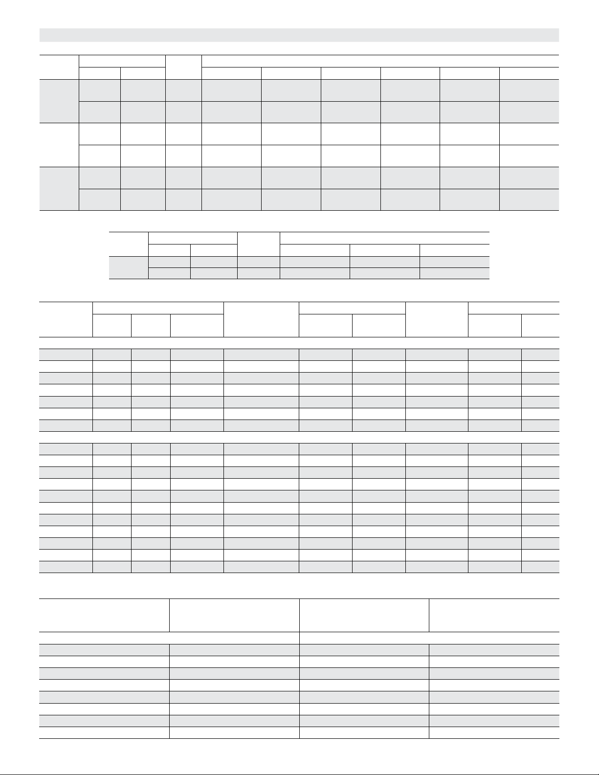
BLOWER DATA
BELT DRIVE KIT SPECIFICATIONS - 036-060
Model
No.
036 0.75 0.86 2 low 449-673
048 0.75 0.86 2 - - - low 497-673
060 1 1.15 2 - - - - - - low 555-833
FACTORY INSTALLED OPTIONS/FIELD INSTALLED ACCESSORY AIR RESISTANCE - in. w.g.
Air
Volume
cfm
036-048 MODELS
800 0.01 0.01 - - - 0.00 0.02 0.02 0.04 0.04 0.05
1000 0.02 0.02 - - - 0.00 0.02 0.02 0.04 0.04 0.07
1200 0.03 0.04 - - - 0.01 0.02 0.02 0.04 0.04 0.07
1400 0.04 0.05 - - - 0.02 0.02 0.03 0.04 0.04 0.07
1600 0.05 0.06 - - - 0.03 0.03 0.04 0.04 0.04 0.07
1800 0.06 0.07 - - - 0.04 0.04 0.05 0.05 0.04 0.07
2000 0.08 0.09 - - - 0.04 0.04 0.06 0.05 0.05 0.08
060-072 MODELS
1000 - - - - - - 0.02 0.00 0.02 0.02 0.04 0.03 0.05
1200 - - - - - - 0.04 0.00 0.02 0.02 0.04 0.03 0.07
1400 - - - - - - 0.05 0.01 0.02 0.03 0.04 0.04 0.07
1600 - - - - - - 0.07 0.02 0.03 0.04 0.04 0.04 0.07
1800 - - - - - - 0.08 0.02 0.03 0.05 0.05 0.05 0.07
2000 - - - - - - 0.10 0.03 0.04 0.06 0.05 0.05 0.07
2200 - - - - - - 0.11 0.04 0.04 0.07 0.05 0.05 0.08
2400 - - - - - - 0.13 0.04 0.05 0.08 0.05 0.05 0.08
2600 - - - - - - 0.15 0.05 0.05 0.09 0.06 0.05 0.08
2800 - - - - - - 0.16 0.05 0.06 0.10 0.06 0.05 0.08
3000 - - - - - - 0.18 0.06 0.07 0.11 0.06 0.05 0.08
Motor HP No. of
Nominal Maximum A01 A02 A03 A05 A06 A07
1 1.15 2 - - - - - - - - - low 598-897
2 2.3 2 - - - - - - - - - - - - low 714-953
2 2.3 2 - - - - - - - - - - - - - - - low 808-1032
Speeds
- - - - - - - - - - - - - - -
high 673-1010
high 745-1117
Drive Kits and RPM Range
- - - - - -
high 897-1346
- - - - - - - - - - - -
hi gh 1071-1429
- - - - - - - - -
high 833-1250
high 1212-1548
BELT DRIVE KIT SPECIFICATIONS - 072
Model
No.
072 1 1.15 1 522-784 - - - - - -
Wet Indoor Coil
036 048 060, 072
Motor HP No. of
Nominal Maximum AA01 AA02 AA03
2 2.3 1 - - - 632-875 798-1105
Speeds
Humiditrol
Dehumidication
Coil
Gas Heating
Medium
Heat
High Heat MERV 8
Economizer
Filters
- - -
MERV
13
POWER EXHAUST FAN PERFORMANCE
Return Air System Static
Pressure
in. w.g.
036-048 MODELS 060-072 MODELS
0.00 2000 0.00 3175
0.05 1990 0.05 2955
0.10 1924 0.10 2685
0.15 1810 0.15 2410
0.20 1664 0.20 2165
0.25 1507 0.25 1920
0.30 1350 0.30 1420
0.35 1210 0.35 1200
Air Volume Exhausted
cfm
Return Air System Static
Pressure
in. w.g.
Page 27
Air Volume Exhausted
cfm
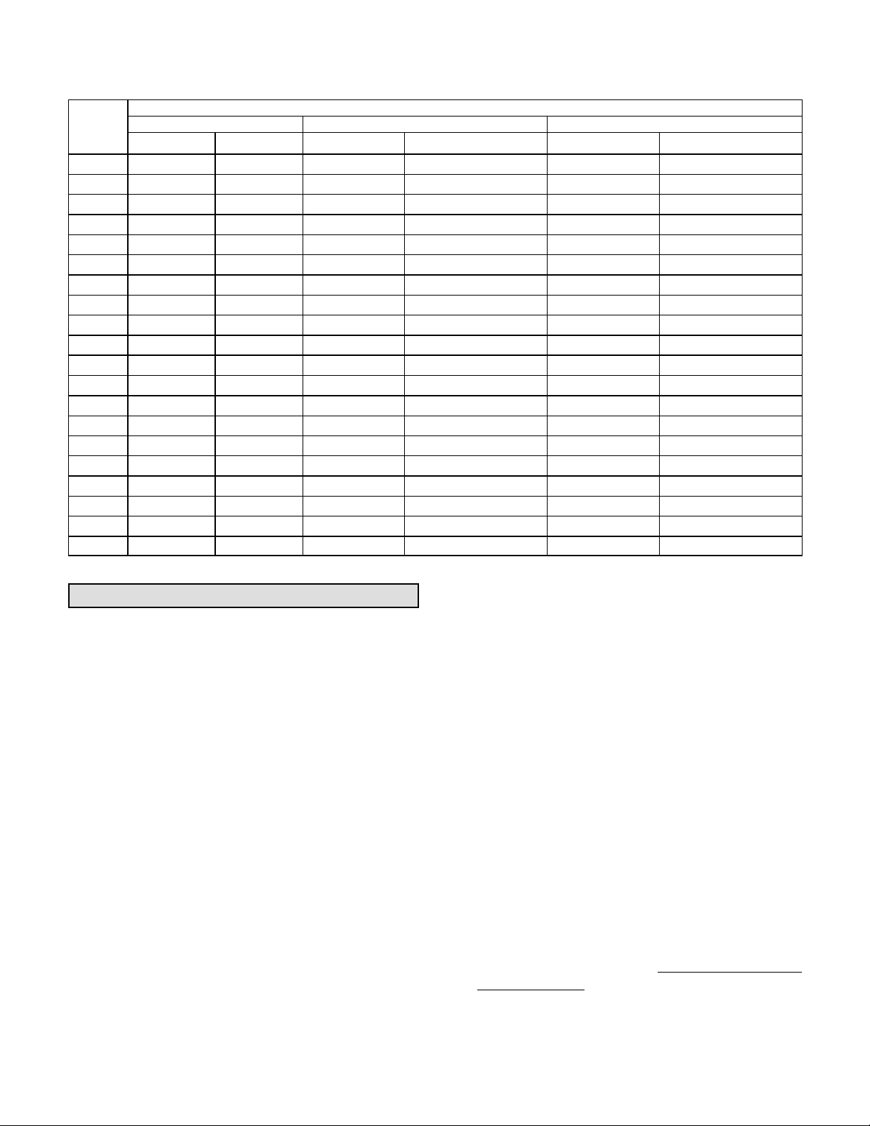
TABLE 6
MANUFACTURER'S DRIVE COMPONENT NUMBERS
DRIVE COMPONENTS
Drive No.
Supplier No. OEM Part No. Supplier No. OEM Part No. Supplier No. OEM Part No.
A01 1VP34x7/8 31K6901 AK54 x 1 100244-19 A40 100245-17
A02 1VP34x7/8 31K6901 AK49 x 1 100244-18 A39 100245-16
A03 1VP34x7/8 31K6901 AK44 x 1 100244-16 A39 100245-16
A05 1VP34x7/8 31K6901 AK41 x 1 100244-15 A39 100245-16
A06 1VP44x7/8 P-8-1488 AK51 x 1 18L2201 A41 100245-18
A07 1VP50x7/8 P-8-2187 AK54 x 1 100244-19 AX43 73K8201
AA01 1VP34x7/8 31K6901 AK69 x 1 37L4701 AX51 13H0101
AA02 1VP40x7/8 79J0301 BK80H
AA03 1VP40x7/8 79J0301 AK59 x 1 31K6801 A50 100245-29
AA04 1VP44x7/8 P-8-1488 AK59 x 1 31K6801 AX51 13H0101
2
A01T
2
A02T
2
A03T
2
A05T
2
A06T
2
A07T
2
AA01T
2
AA02T
2
AA03T
2
AA04T
NOTES: 1 Requires split taper bushing, Browning no. H1; OEM no. 100073-04
Cooling Start-Up
Motor Pulley Blower Pulley bELT
1
1VP34x7/8 31K6901 AK54 x 1 100244-19 A41 100245-18
1VP34x7/8 31K6901 AK49 x 1 100244-18 A40 100245-17
1VP34x7/8 31K6901 AK44 x 1 100244-16 A40 100245-17
1VP34x7/8 31K6901 AK41 x 1 100244-15 A41 100245-18
1VP44x7/8 P-8-1488 AK51 x 1 18L2201 A41 100245-18
1VP50x7/8 P-8-2187 AK54 x 1 100244-19 AX43 73K8201
1VP34x7/8 31K6901 AK69 x 1 37L4701 A50 100245-29
1VP40x7/8 79J0301 BK80H* 100788-03 A52 100245-30
1VP40x7/8 79J0301 AK59 x 1 31K6801 A49 100245-32
1VP44x7/8 P-8-1488 AK59 x 1 31K6801 A50 100245-29
100788-03 A53 P-8-4951
2
Includes tension assembly, Fenner no. FS0590; OEM no. 101994-02
5- Refer to Cooling Operation and Adjustment section for
proper method to check refrigerant charge.
A-Operation
1- Initiate first and second stage cooling demands
according to instructions provided with Unit
Controller Installation and Setup Guide. Use the
menu navigation arrows and select button; see
Service - Test.
2- No Economizer Installed in Unit -
A first-stage cooling demand (Y1) will energize the
compressor and blower in low speed along with the
condenser fan. An increased cooling demand (Y2)
will increase the blower and compressor to high
speed.
Units Equipped With Economizer -
When outdoor air is acceptable, a first-stage
cooling demand (Y1) will energize the economizer.
An increased cooling demand (Y2) will energize
the compressor and low speed blower along with
the condenser fan. When outdoor air is not
acceptable unit will operate as though no
economizer is installed.
3- Units contain one refrigerant circuit or stage.
4- Unit is charged with R-410A refrigerant. See unit
rating plate for correct amount of charge.
B-Three Phase Scroll Compressor Voltage Phasing
Three phase scroll compressors must be phased
sequentially to ensure correct compressor and blower
rotation and operation. Compressor and blower are
wired in phase at the factory. Power wires are
color-coded as follows: line 1-red, line 2-yellow, line
3-blue.
1- Observe suction and discharge pressures and
blower rotation on unit start-up.
2- Suction pressure must drop, discharge pressure
must rise, and blower rotation must match rotation
marking.
If pressure differential is not observed or blower rotation is
not correct:
3- Disconnect all remote electrical power supplies.
4- Reverse any two field-installed wires connected to
the line side of K1 contactor. Do not reverse wires at
blower contactor.
5- Make sure the connections are tight.
Discharge and suction pressures should operate at
their normal start‐up ranges.
Page 28
LGH/LCH036, 048, 060, 072
 Loading...