

CONTENTS
1
Page
Compact Waterside Fan Coil Specification 2
Mounting 3
Pipework Connections 3
Duct Connections 3
Electrical Connections 4
Controls 4
Fan Speed Settings 5
Periodic Maintenance 6
Electrical Data 7
Coil Water Content 7
Weights 7
Minimum No. Spigots 7
Coil Connections 7
General Arrangement Drgs
Unit Ref: Drg Ref:
LC22 Z304255 (2 pages) 13-14
LC31 Z304256
LC45 Z304257
LC60 Z304258
LC76 Z304259
Example Wiring Diagrams 8-12
(2 pages) 15-16
(2 pages) 17-18
(2 pages) 19-20
(2 pages) 21-22
R
LENN X
EUROVENT
CERTIFIED PERFORMANCE
Manufacturer reserves the right to change any product specifications without notice.
CASINGS
The casings shall consist of durable 1.2mm (18 gauge)
galvanised steel reinforced to form a rigid monoque
structure. All edges to be radiused and access panels to
be fixed with easy release self retaining fasteners.
DISCHARGE PLENUM
The discharge plenum shall be wholly lined with Class O
acoustic insulation. The plenum shall be provided with
200mm diameter spigots for duct connection.
DRIP TRAY
The drip tray shall be manufactured such that when the
unit is mounted level there shall be a positive fall for the
condensate water to the drain connection from all areas
of the drip tray. There shall be no areas where the water
can collect in pools. The drip tray shall be of single
component construction and be located under the coil
assembly and extend to include the valve pack
arrangement. The tray shall be fully insulated.
FANS
Double inlet double width fans shall be used, driven by a
motor using cradle type resilient mountings. The fan
impellers shall be 160mm diameter and of 'Tablock'
construction to ensure good performance and low noise.
Each impeller shall be dynamically balanced.
MOTORS
Motors shall be single speed permanent split capacitor
type. The motors used shall comply with BS5000 Part 11
1973 (revised 1 989). Speed control shall be achieved by
applying a variable voltage to the motor winding. Motors
are to have maintenance free sealed f or life bearings and
built in thermal overload protection.
INSULATION
Dual function thermal and acoustic insulation shall be
used and shall be to Class 0 specification.
COILS
All heat exchangers shall be tested at a minimum of 25
bar pressure. The coils shall be manufactured using
solid drawn copper tubes and aluminium fins. Each coil
shall be fitted with an air vent and drain cock.
COIL CONNECTIONS
All are to be BS2871 Part 1: 1971 and suitable for brazed
and compression fittings. Coil connections shall be at
40mm centres to enable easy fitment of industry
standard water control valves.
FILTERS
Standard filters shall be of washable type. They shall
have a performance classification of G2 in accordance
with EN779 (EU2) and flame resistance to DIN 53438:
Class 1
CONTROLS
All units shall be fitted with an illuminated On/Off switch
and three speed selector switch. Adjacent to this switch
are two additional switches that provide a fine tuning
capability. In total a selection of 27 speeds are available
with design settings factory set, and dependant on
transformer tapping connections. The unit is supplied
with a 24 volt AC transformer output to drive controllers
and actuators. The control box shall be of a hinge
arrangement with a single screw access to terminal strips
for customer connection.
PACKAGING
Units shall be supplied with shrink wrapped packaging to
prevent damage and dust contamination. Units shall be
clearly marked with the model identification and site
reference and supplied with installation instructions.
The units will be despatched on pallets with 5 or 6 units
per pallet dependant on unit sizes.
CERTIFICATION
Units shall be supplied with a CE label designating that
they comply with CE requirements for safety .
COMPACT WATERSIDE FAN COIL SPECIFICATION
2
R
LENN X
Thank you for choosing the Lennox Quantum Compact
Fan Coil Unit. Please read the following information
carefully prior to installation. These instructions should
be kept in a safe place for future reference.
WARNING:
ISOLATE FROM THE ELECTRICAL SUPPLY
BEFORE COMMENCING WORK.
These units can be installed virtually as delivered. They
are intended for fitting behind a suspended ceiling or a
similar ceiling void and have circular spigots for
connecting to ducting. Similarly, they can have a fresh air
spigot fitted when specified.
MOUNTING
In all cases, the units are fixed to the mounting face by
means of four slots in the end flanges. Down rods, 10mm
in diameter, should be used t o support units
1. Unistrut should be mounted to the slab (see
dimensional data) and four 10mm down rods fix ed to
the unistrut.
2. The down rods should have two nuts and two w ashers
to lock the unit in position. The unit can then be lifted
into location, hooking the slots (in the top panel) over
the washers. The nuts must then be securely
tightened.
3. Check to ensure the unit is level and adjust if
necessary.
4. Check that water runs into the waste from the drain
tray, by pouring wat er into it.
NOTE: To allow f or Service Clearances it is recommended
that a minimum space of 50mm is provided from top of
the unit to underside of slab.
Sufficient space should be provided to allow for clear and
safe access to the control panel.
PIPEWORK CONNECTIONS
1. Water flow and return connection
Plain pipe connection tails are all to BS 2871, Part 1:
1971 and are suitable for brazed or compression fittings.
Connection sizes are 22mm outside diameter on the
cooling coil and 15mm on the heating coil. Actual final
connection pipesizes will vary depending on valve
configuration where fitted.
2. Condensate Tray Connection
An end facing 22mm outside diameter copper
condensate drain connection tube to BS 2871, Part 1:
1971 is fitted as standard to the condensate tray on all
units.
3. Air Vents and Drains
Brass air vent and drain tapping points are fitted as
standard to all coils. These are positioned at the top and
bottom of the header tubes.
DUCT CONNECTIONS
1. Discharge Air Side
An integral discharge plenum is fitted as standard
complete with 19 7mm outside diameter circular spigots.
These are to accept standard 200mm diameter flexible
ducting. Blanking caps are available to order .
2. Inlet Air Side
When specified, units will be fitted with an Air Inlet
Plenum, this will have the same number, size and
position of circular spigots as on the discharge air side.
Blanking caps are available subject to order .
3. Fresh Air Spigot
The fresh air spigot is available in a size of 100mm
diameter.
4. Condensate pump
Condensate pump kits are available as an optional
factory fitted option. Refer to diagrams indicating
electrical wiring details.
5. Electrical heating element
LC22 2KW LC31 2KW
LC45 2KW LC60 4KW
LC76 4KW
Refer to diagrams indicating electrical wiring details.
MOUNTING / CONNECTIONS
3
R
LENN X

ELECTRICAL CONNECTIONS
ISOLATE ELECTRICAL SUPPLY BEFORE
ATTEMPTING SERVICE WORK.
A 230V, 50Hz, single phase supply is required. Wiring
must be installed by a qualified electrician and conform
to current local and national regulations.
1. Wire mains to unit via a double pole isolating switch,
fused at 3 amp. Refer to diagrams indicating
electrical wiring details.
2. The electrical connection is via a 2m flying lead with
factory fitted connector into socket on control box
where an electric heater is NOT fitted. If an electric
heater is fitted, to connect mains supply to unit,
slacken off the screw holding the control box front
cover. Carefully pivot the cover to support it, making
sure the wires connecting the cover to the unit are not
strained. Connect the mains lead via grommet hole
in the side panel to the LIVE, NEUTRAL and EARTH
positions on the 12-way terminal block. Replace
cover and tighten screw .
3. If a Condensate Lift Pump is specified, this will be
pre-wired back to the control box, but the pump
assembly will be taped to the unit and must be fixed to
the end of the drip tray before installing the unit, using
the screws supplied.
4. The fan motors are of the permanent split capacitor
type and have a capacitor fixed to the outside of the
motor. All motors have thermal overload protection
as standard. Access to the fan tray is via removable
panels on the bottom face of the unit.
CONTROLS
All units are fitted as standard with an ON/OFF switch and
a FAN SPEED selector switch for three speeds.
When specified, the water control valves will have a
controller that will be fitted to the exterior of the control
box.
These are all fitted into the control box and pre-wired.
1. Fan Speed
Out of 6 speeds available, SL (Super Low), EL(Extra Low),
L(Low), ML(Med/Low), M(Med), and H(High), the fan
speed selector switch will be wired for three speeds.
Speed adjustment and fine tuning is achieved by
following the instructions indicated on the label that is
positioned on the underside of the unit, adjacent to the
control box.
Each model size has its specific settings, examples as
detailed on page 5 of this document.
An example of adjusting the speed setting is described
below:-
E.g.: If unit is selected for Medium/Low (ML) speed,
then the speed selector switch is set at position II and
other positions L and M, as below:
Position I = L (Low Speed)
Position II = ML(Med/LowSpeed)
Position III = M (Medium Speed)
If selected speed is EL then this would be Position II with
SL and L other positions. If selected speed is H then this
would be posiition III with M and ML other positions.
ELECTRICAL CONNECTIONS / CONTROLS
R
LENN X
4
FAN SPEED SETTINGS
5
R
LENN X
III
II
I
I I I
O O O
ON +5v +10v 3 spd
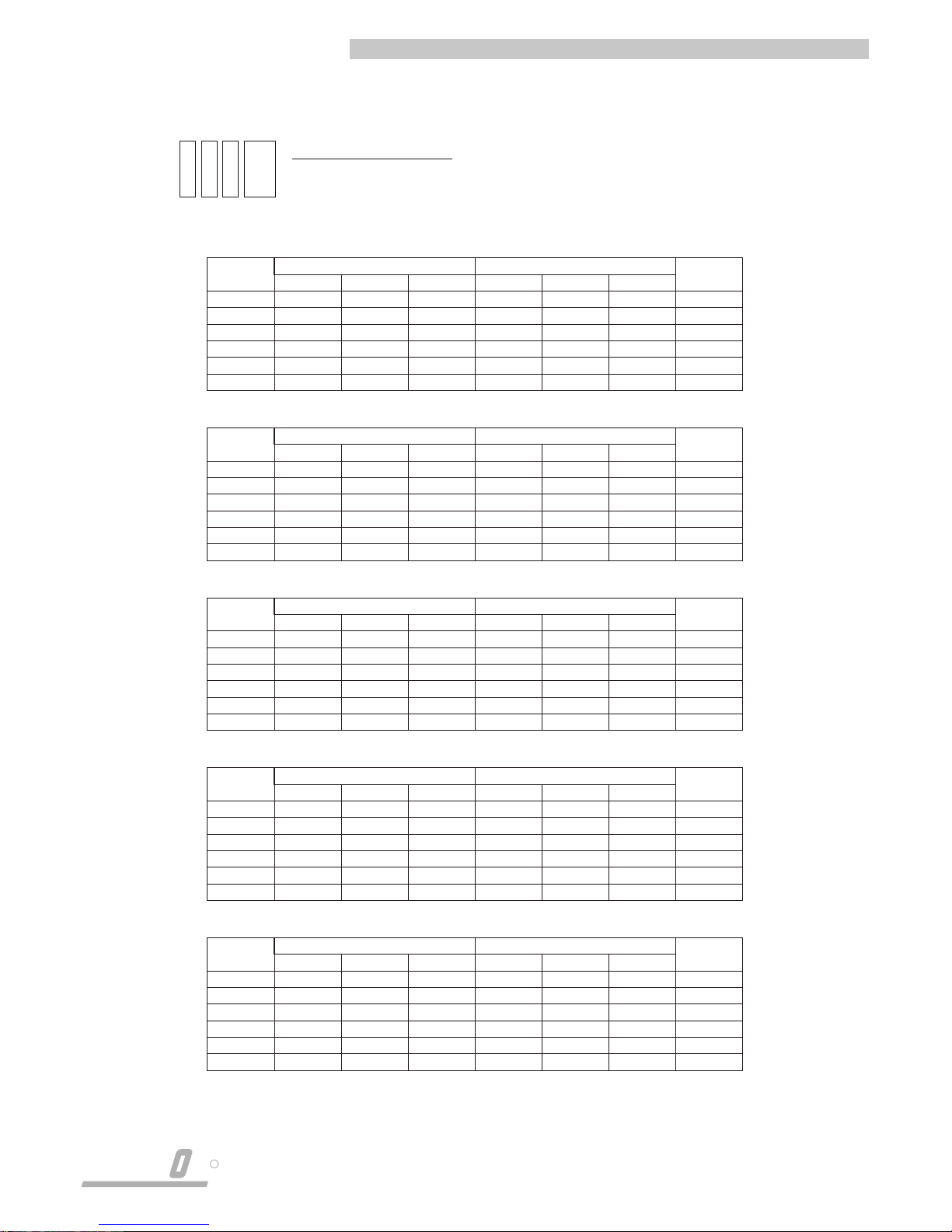
FAN SPEED SETTINGS
To achieve the design speed use a combination of main tappings on
the transformer and switch positions on the outside of the control box.
LC22
SL
EL
L
ML
M
H
Wh
120
120
135
135
150
150
Yel
135
135
150
150
165
165
Rd
150
150
165
165
180
180
3 spd
I
II
II
II
II
III
+ 10v
I
O
O
I
O
I
+ 5v
O
I
O
O
I
O
OUTPUT
VOLTS
130
140
150
160
170
190
SWITCH POSITIONS
MAIN TAPPINGS
LC31
LC45
LC60
LC76
SL
EL
L
ML
M
H
SL
EL
L
ML
M
H
SL
EL
L
ML
M
H
SL
EL
L
ML
M
H
Wh
120
120
135
135
150
150
Wh
120
120
135
150
165
165
Wh
120
120
135
135
150
150
Wh
120
120
135
150
165
165
Yel
135
135
150
150
165
165
Yel
135
135
150
165
180
180
Yel
135
135
150
150
165
165
Yel
135
135
150
165
180
180
Rd
150
150
165
165
180
180
Rd
150
150
165
180
195
195
Rd
150
150
165
165
180
180
Rd
150
150
165
180
195
195
3 spd
I
II
II
II
II
III
3 spd
I
II
II
II
II
III
3 spd
I
II
II
II
II
III
3 spd
I
II
II
II
II
III
+ 10v
I
O
O
I
O
0
+ 10v
I
O
O
O
I
I
+ 10v
I
O
O
I
O
I
+ 10v
I
I
O
O
O
O
+ 5v
O
I
O
O
I
O
+ 5v
O
I
I
I
O
O
+ 5v
O
I
O
O
I
O
+ 5v
O
O
I
I
O
I
OUTPUT
VOLTS
130
140
150
160
170
180
OUTPUT
VOLTS
130
140
155
170
190
205
OUTPUT
VOLTS
130
140
150
160
170
190
OUTPUT
VOLTS
130
145
155
170
180
200
SWITCH POSITIONS
SWITCH POSITIONS
SWITCH POSITIONS
SWITCH POSITIONS
MAIN TAPPINGS
MAIN TAPPINGS
MAIN TAPPINGS
MAIN TAPPINGS

PERIODIC MAINTENANCE PROCEDURE
The following routine maintenance operations should be
carried out twice a year or at such shorter intervals as
may be dictated by climatic conditions or cleanliness of
conditioned space.
1. Routine Precautions
SWITCH OFF POWER SUPPLY AT THE MAINS OUTLET
BEFORE COMMENCING ANY WORK ON THE
EQUIPMENT.
DO NOT OPERATE FAN FOR LONG PERIODS (OVER 2
HOURS) UNDER FREE AIR CONDITIONS. I.E WITHOUT
DUCTWORK CONNECTED.
DO NOT USE STEAM JET OR HIGH PRESSURE HOT
WATER TO CLEAN COIL SURFACES.
2. General
!
Thoroughly clean chassis, baseplate, drain tray .
!
Clean casing. The unit exterior surfaces should be
inspected monthly and any signs of corrosion or
scratches should be treated immediately.
3. Routine Checks
!
Check voltage at supply point with unit running.
4. Condensate Trays
!
Check condensate drains are clean and free running.
! Check condensate hose connections are secure
and leak free.
!
Clean the condensate tray thoroughly .
!
Check and clean condensate pump if fitted.
!
Check operation of tray, drains or pump by
introducing water into tray .
5. Controls
!
Check all connections for burning or wear . Replace if
necessary.
!
Ensure all electrical connections are secure.
!
Check functions of controls according to operating
procedures.
6. Fan Motor and Fan
A regular check on the fan/motor assembly is
advisable to ascertain if any overheating of the motor
is occurring and that the fan impeller is free running
and has not sustained any damage.
Check that fans and fan motor are properly
aligned.
Check all securing screws, bolts and nuts are tight.
7. Coil
The coil should be inspected every six months to
ascertain if any foreign matter has accumulated
between the fins and that the coil connections are
free from leaks.
Should the fins become contaminated too frequently,
it is advisable to check that the air filter is functioning
correctly.
Use a soft brush and vacuum cleaner to remove any
dust between fins. Comb fins if required.
DO NOT RUN UNIT WITHOUT FILTER FITTED.
8. Filter
Regular cleaning of return air filter is essential, every
three to six months depending on the working
environment of the unit. Dirty filters will reduce the
air volume handled by the unit, thus adversely
affecting its performance.
Clean the filter using a vacuum cleaner OR remove
the filter from the unit and fully immerse in warm
water with a mild detergent. Rinse in clear water,
allow to dry before replacing.
PERIODIC MAINTENANCE
R
LENN X
6
H
M
ML
L
EL
SL
H
M
ML
L
EL
SL
H
M
ML
L
EL
SL
H
M
ML
L
EL
SL
H
M
ML
L
EL
SL
190
170
160
150
140
130
180
170
160
150
140
130
205
190
170
155
140
130
190
170
160
150
140
130
200
180
170
155
145
130
75
66
61
56
51
47
132
118
110
100
90
82
158
144
127
112
96
85
213
187
176
157
148
130
271
252
238
220
200
171
0.37
0.33
0.31
0.29
0.28
0.27
0.67
0.62
0.58
0.53
0.48
0.45
0.84
0.77
0.68
0.61
0.53
0.48
1.01
0.89
0.85
0.76
0.72
0.65
1.35
1.24
1.18
1.08
1.00
0.86
0.52
0.47
0.44
0.41
0.39
0.37
0.94
0.86
0.81
0.74
0.68
0.63
1.18
1.08
0.95
0.85
0.75
0.67
1.41
1.25
1.18
1.06
1.01
0.90
1.89
1.73
1.65
1.52
1.40
1.21
MODEL
LC22
LC31
LC45
LC60
LC76
MODEL
LC22
LC31
LC45
LC60
LC76
WEIGHT
kg
MINIMUM No. SPIGOTS COIL CONNECTIONS (mm)
Total CWFront LPHW
30
39
49
54
73
2
2
2
3
3
1
1
1
2
2
22
22
22
22
22
15
15
15
15
15
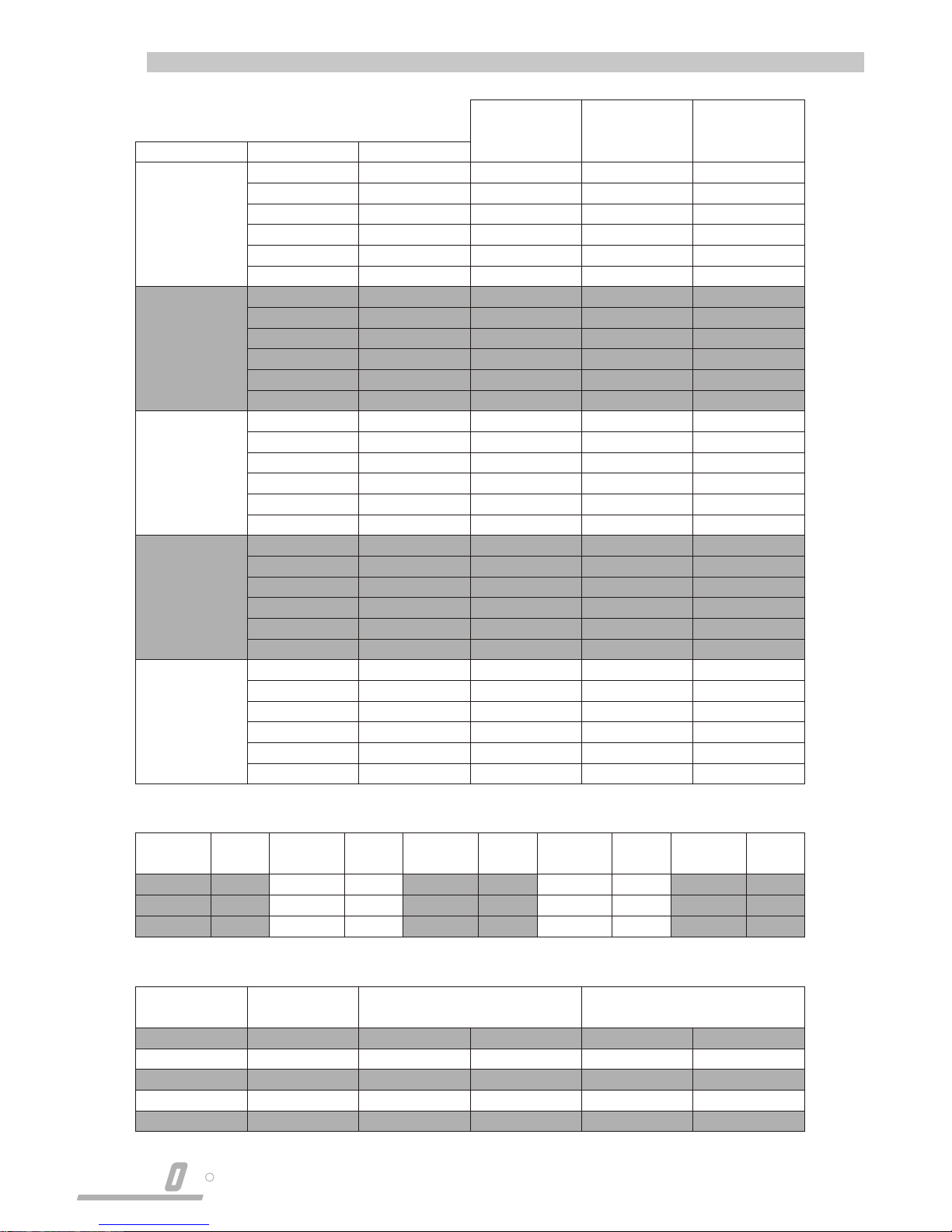
FAN SPEED VOLTS
MOTOR
POWER
W
FULL LOAD
CURRENT
A
START
CURRENT
A
MODEL
WATER
CONTENT
(LITRES)
LC22 HEATING
LC22/3 ROW
LC22/4 ROW
0.19
1.32
1.50
MODEL
WATER
CONTENT
(LITRES)
LC31 HEATING
LC31/3 ROW
LC31/4 ROW
0.25
1.72
1.97
MODEL
WATER
CONTENT
(LITRES)
LC45 HEATING
LC45/3 ROW
LC45/4 ROW
0.35
2.47
2.83
MODEL
WATER
CONTENT
(LITRES)
LC60 HEATING
LC60/3 ROW
LC60/4 ROW
0.41
2.84
3.25
MODEL
WATER
CONTENT
(LITRES)
LC76 HEATING
LC76/3 ROW
LC76/4 ROW
0.53
3.73
4.27
7
R
LENN X
DATA
ELECTRICAL DATA
COIL WATER CONTENT
WEIGHTS, MINIMUM No. SPIGOTS, COIL CONNECTIONS
 Loading...