

Page 1
HEAT PUMP KITS AND ACCESSORIES
Litho U,S,A.
©1993 LennoxIndustries Inc.
Dallas,Texas 9/93
502,673M
Supersedes 3/92
SOLID STATE DEFROST
REPLACEMENT BOARD
INSTALLATION INSTRUCTIONS FOR SOLID STATE DEFROST REPLACEMENT BOARD
LB-83114C (61H42) USED ON HP7-1, -2, HP8, CliP9 AND CliP10 SERIES UNITS
,/SHIPPINGANDPACKING _ : : :: : ]
Package 1 of 1 contains:
1- Control board on mounting bracket
1- Defrost thermostat
1- Outdoor fan/defrost relay
8- Wires with 3/16" terminals
1- Screw
2- Wire nuts
/tNSTA_TiON: :
1- Turn off power supply to unit.
2- Remove compressor access panel and control
box cover.
A- Defrost Thermostat
3- Disconnect coil thermistor from coil return bend
and air thermistor from fan section. Replace coil
thermistor with provided defrost thermostat.
Secure to liquid line as close as possible to the
outdoor coil.
NOTE-/t may be necessary to remove the front corner
panel for access to coil thermistor,
B-Defrost Board
4- Remove and retain screwfrom existing solid state
defrost board located in control box. Note
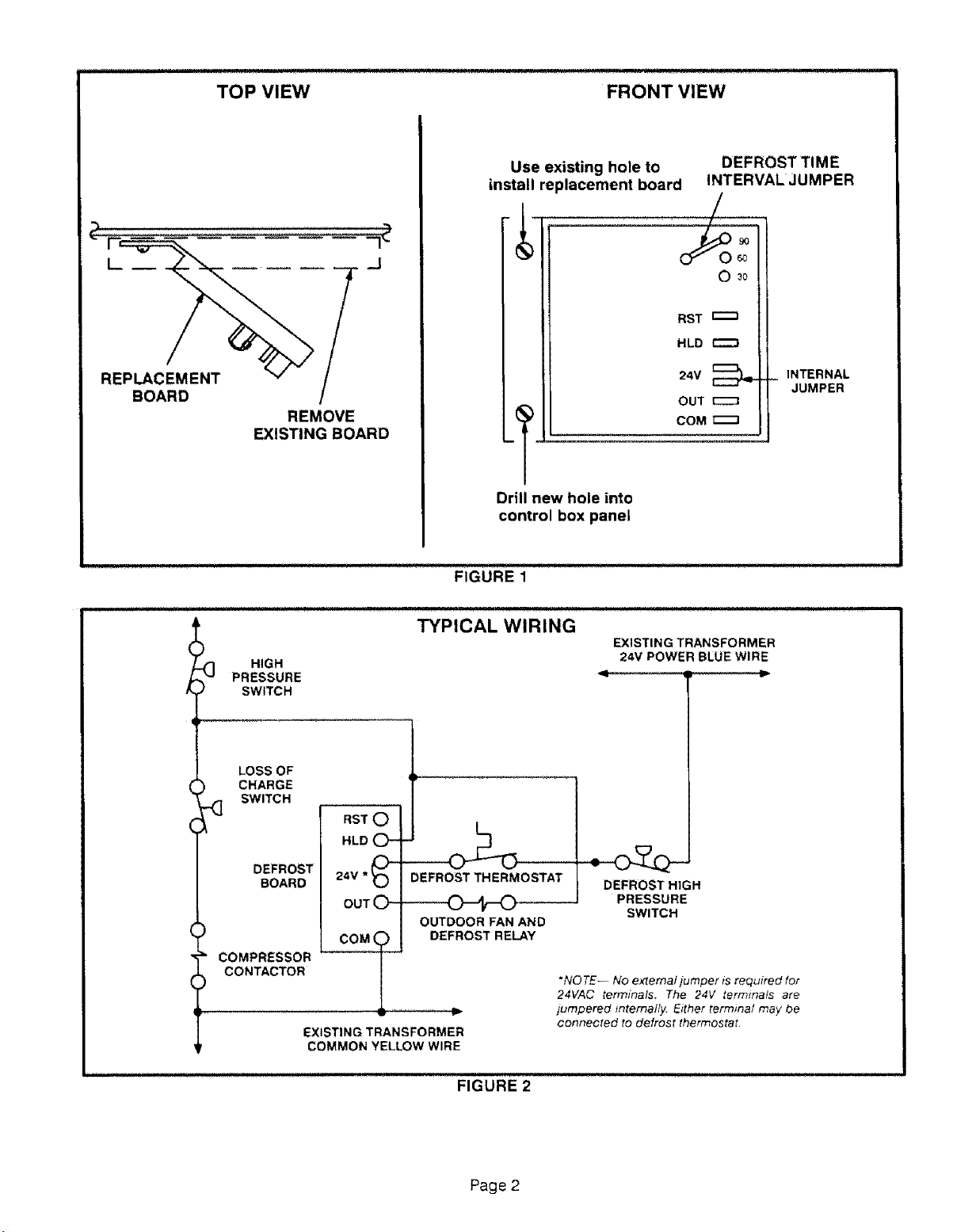
existing wiring. See figure 1.
5- Install newcontrol board assembly using existing
screw and hole.
6- Drill new hole into control panel and secure with
screw provided in kit.
C-Outdoor Fan/Defrost Relay
7- Remove outdoor fan/defrost relay. Install
replacement outdoor fan/defrost relay.
1- Connect one end of long wire (provided) to "HLD"
terminal on the defrost board. Disconnect defrost
high pressure switch from between high pressure
switch and loss of charge switch.
2-Splice remaining end of long wire to wire
between high pressure switch and toss of charge
switch where high pressure switch was originally
connected.
3- Connect onewire from defrost relaycoitto "OUT"
terminal of defrost board.
4- Cut off terminal of remaining wire from defrost
relay coil and strip wire 5/8 inch. At a convenient
location, splice wire to long wire from "HLD"
terminal using a wire nut.
5- Connect wire from defrost thermostat to one of
the "24V" terminals on defrost board.
IMPORTANT-Make sure defrost thermostat is securely
fastened to the fiquid line.
6- Cut off terminal from remaining defrost
thermostat wire and strip wire 5/8 inch. Splice
with one of the defrost pressure switch wires
using a wire nut.
7- Locate blue transformer wire and splice with
remaining defrost high pressure switch wire
using a wire nut.
8- Connect the remaining existing wire to "COM"
terminal on defrost board.
9- Defrost time interval can be selected to defrost
every 30, 60 or 90 minutes. This is selected using
the jumper on the defrost board.
10-Replace all panels and restore power to unit.
Page 1
Page 2
TOP VIEW FRONT VIEW
REPLACEMENT
BOARD
_J
f
REMOVE
EXISTING BOARD
Use existing hole to
install replacement board
I
®1
Drill new hole into
control box panel
FIGURE 1
DEFROST TIME
INTERVAL JUMPER
9O
6O
0 _o
RST
HLD
24V
OUT
COM
_ INTERNAL
JUMPER
_] HIGH
PRESSURE
SWITCH
LOSS OF
, CHARGE
._ SWITCH
DEFROST
BOARD
COMPRESSOR
CONTACTOR
TYPICAL WIRING
RST 0
HLD
24V * _)-
OUT (_
tOM9
EXISTING TRANSFORMER
COMMON YELLOW WIRE
DEFROST THERMOSTAT
OUTDOOR FAN AND
DEFROST RELAY
EXISTING TRANSFORMER
24V POWER BLUE WIRE
DEFROST HIGH
PRESSURE
SWITCH
*NO TE-- No external/umper tsrequtred for
24VAC terminals. The 2,4V terminals are
jumpered lnternal/}z Either termina/ may be
connected to defrost thermostat•
Page 2
Page 3

The defrost control is a solid state control
manufacturedby HamiltonStandard.The control
providesautomaticswitchingfrom normalheating
operationto defrostmode and back.The defrost
controlcontainsasolidstatetimerwhichswitchesan
externa] defrost relay through 1/4" male spades
mountedonthecontrol'scircuitboard.Thecontrol
energizesthedefrostrelayat regular timed intervals.
On some units, anormally open defrost switch placed
in series between the defrost relay and the control
initiates defrost only when needed at the end of the
timed intervals. On other units, the control initiates
defrost on demand from the defrost thermostat,
Defrost Control Components:
1- 24V Terminal
Terminat 24V receives 24VAC from the control
transformer. This terminal powers the control's
internal timer and relays. Terminal 24V must be
powered at all times to provide HOLD between
thermostat demands.
2 COM Terminal
Terminal COM provides 24VAC common.
3- HLD Terminal
Terminal HLD hold the internal timer in place
between thermostat demands and altows the unit
to continue timing upon resumption of
thermostat demand, tn most units, terminal HLD
is connected directly to thermostat demand.
4- OUT Terminal
Terminal OUT controls unit defrost when
connected to one side of the defrost relay coil. An
internal relay connected to terminal OUT closes
to allow external defrost relay to energize and
initiate defrost. At the end of the defrost period,
the internal relay connected to terminal OUT
opens to de-energize the external defrost relay.
5- RST Terminal
This terminal is not functional for the specified
application.
6- Timing Pins (T1,T2,T3)
Each of these pins provides a different timed
interval between defrosts (30, 60 or 90 seconds).
A jumper connects the pins to circuit board
terminal Wl. To change the interval between
defrosts, remove the jumper from the pin it is
connected to and reconnect the jumper to one of
the other available pins.
7- Timing Jumper
A factory installed jumper on the circuit board
connects terminal Wl on the circuit board to one
of the three timing pins.
8- TST Pins
Each board is equipped with a test pins for use in
troubleshooting the unit. When jumpered
together, these pins reduce the control timing to
about 1/256 original time.
A CAUTION
To Place Control in Test Mode:
1- Turn off all power to avoid damaging the circuit
board.
2- Make sure all control terminats are connected as
shown on unit wiring diagram before attempting
to place control in test mode.
IMPORTANT
3- Connect jumper to "TST" pins,
4- Turn indoor thermostat to heat mode and adjust
to highest temperature setting.
5- See table 1 for control timings in "TST" mode,
6- Turn on power to unit and re-adjust thermostat.
Be sure to remove jumper when test is complete.
TABLE 1
TEST MODE CONTROL TIMINGS
NORMAL !_ 30+3 60±6 : 90_9 _ 14+1,4
OPERATION MIN MIN i MIN. MIN.
"TST" PINS
JUMPERED SEC. i SEC i SEC* i SEC
TOGETHER !
1!7+0r7 14+1A i 21_+21 3-3_0.3
Page 3
Page 4

DEFROST CONTROL TROUBLESHOOTING FLOWCHART
START HERE
I
Check control transformer primary
and secondary voltages. Repair or
replace as necessary.
I
Turn off power to unit.
I
Check defrost sensor. Is sensor
temperature or pressure acti-
vated? For help in determining, re-
fer to operation of control in unit
installation instructions and unit
wiring diagram.
I
I I
Pressure Temperatu re
Is sensor making good
Yes _ No
Check all electrical connections
at the defrost control. Defrost
sensor and defrost relay.
I
Connect a jumper across
the defrost relay.
I
Connect a jumper across the two
"TST" pins on the delrost Control,
I
Turn indoor thermostat to
heat mode and adjust to high-
est temperature setting.
1
Turn on power to unit.
I
Check voltage across "HLD"
terminal and "COM" termi-
nal, Is voltage 24 + 6VAC?
1
ls solenoid engaging?
Yes _t No
i 1
Replace reversing Replace solenoid.
valve. Repeat Repeat troubleshoot-
troubleshooting ing procedure,
procedure.
I
contact with coil?
Repair or
replace sensor
bracket.
I
............i .... 1 .o___1
Is defrost control set for Is compressor contactor
30, 60 or 90 minute de = energized?
frost intervals?
i---No ................I Yes
Check thermostat and
thermostat widng. Repair
or replace as necessary
I
Repeat troubleshooting
procedure.
Does un_ go into defrost
within appropriate time? I
Yes No _ procedure.
Check circuit from "HLD"
terminal back to thermo-
stat, Repair or replace as
necessary.
t
|
Repeat troubleshooting
i ]
Unit is operating properly. Check voltage across "OUT"
Turn off power to unit, terminal and "COM" terminal.
Remove all test jumpers. Is voltage 24 ± 6VAC?
I
Yes
Check and repair circuit
through defrost relay to
Repeat troubleshooting
Reassemble unit.
Connect a jumper between "OUT" terminal
and "COM" terminal. CAUTION-Be careful
not to short "OUT" terminal to "24v" terminal,
Permanent controt damage could result.
Does unit go immediately into defrost?
Yes t
I
Turn off power to unit.
Remove all test jumpers.
Replace defrost control with new
control board,
Repeat troubleshooting procedure.
Check voltage across re=
versing valve coil. Is volt-
age 24 ÷ 6VAC?
I
I
No
I
Turn off power to unit.
from reversing valve
control transformer.
procedure.
Yes
I
I
["-_ Yes _ No
Is defrost relay
energized?
Yes
Turn off power to unit.
Check circuit from defrost
switch back to control
transformer. Repair of re-
place as necessary,
Repeat troubleshooting
procedure,
I No
Check voltage across "24Y"
terminal and "COM" terminal. Is
NO ,,,, ,,,,,,
I
No
Check voltage across de-
frost relay coil. Is voltage
24 ± 6VAC?
I
voltage 24 ± 6VAC?
I
_ ..... Yes
I
Turn off power to unit.
Replace defrost relay,
Repeat troubleshooting
procedure.
Page 4
 Loading...