

Lennox LB57113BM Installation Insrtuctions
Page 1
INSTALLATION INSTRUCTIONS FOR LOW AMBIENT CONTROL KIT LB-57113BM (27J00)
USED WITH SINGLE-COMPRESSOR HEAT PUMP UNITS
Litho U.S.A.
502,818M
11/98
Supersedes 3/96
®
E1998 Lennox Industries Inc.
Dallas, Texas
LOW AMBIENT CONTROL KIT
KITS COMMON TO HEATING
AND COOLING EQUIPMENT
INSTALLATION INSTRUCTIONS
SHIPPING AND PACKING LIST
Package 1 of 1 contains:
1- Low ambient pressure switch assembly (S11)
1- 36" (914 mm) length of 1/4" (6.35 mm) copper tube
with flare nuts
1- Relay
1- 20ĆFoot length of wire
4- 20" Lengths of wire
1- Bag assembly each containing:
8-Wire nuts
2-Saddle valves
4-#10-16 X 5/8" S.D.S.T. screws
1-Schrader depressor tee with seal cap
APPLICATION
The low ambient pressure switch (S11) cycles the
outdoor fan while allowing compressor operation in the
cooling cycle. This intermittent fan operation results in
a high evaporating temperature which allows the
system to operate without icing the evaporator coil and
losing capacity. This kit is designed for use in ambient
temperatures no lower than 30°F.
Lennox recommends a belly-band style crankcase heater
(P-8-8852, 240v, 45w) be added to compressors which
do not have one. A freezestat (LB-62858CA) should also
be added to any system using a low ambient kit.
NOTE - Do not use this low ambient kit on units with
capillary tube metering devices. Install an expansion
valve metering device if using this kit.
INSTALLATION
A-Pressure Switch Assembly
1- Disconnect power to unit.
2- Remove compressor compartment access panel.
3- Install valve depressor tee discharge line gauge port.
4- Install pressure switch in compressor compartment
with screws provided. Switch should be installed in a
vertical position higher than mid-point of compressor.
See figure 1.
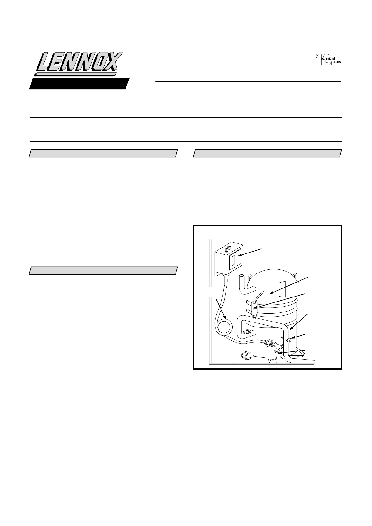
FIGURE 1
TYPICAL INSTALLATION
S11 LOW AMBIENT
PRESSURE SWITCH
HIGH
PRESSURE
SWITCH
COMPRESSOR
DISCHARGE
LINE
S24 LOSS
OF CHARGE
SWITCH
VALV E
DEPRESSOR
TEE
SHOCK
LOOP
5- Connect copper line to low ambient pressure
switch and open side of depressor tee (provided).
Provide a shock loop in copper tubing to prevent
breakage from vibration. Tighten connections.
Depressor tee port with valve core is used as
service port. If necessary, valve core can be moved
to other leg of tee.
B-Low Ambient Pressure Switch Setting (S11)
One of two types of pressure switches are provided. The
Ranco switch has one square and one round adjustment
knob and the Alco switch has two square adjustment
knobs.
Ranco Model
The low ambient pressure switch provided in the kit is
factory set for 285 psig (1965 kPa) cut-in and 140 psig
(965 kPa) cut-out.
If necessary, adjust low ambient pressure switch as
follows:
1-Rotate round knob to set cut-in pressure. Refer to right
set of indicating numbers on face of control. See
figure 3.
2- Rotate square knob to set differential indicator to 145
psig (999 kPa). Refer to left set of indicating numbers.
Alco Model
If necessary, adjust low ambient pressure switch as
follows:
1-Rotate the square knob located on the left to set cut-in
pressure. Refer to left set of indicating numbers on
face of control. See figure 2.
2- Rotate the square knob located on the right to set
differential indicator to 145 psig (999 kPa). Refer to
right set of indicating numbers.
3- Use only terminals 1 and 4 when connecting wiring.
NOTE - Disregard Cut out minus Diff. is Cut In"
statement on face of control. This does not apply in this
application.
C-Low Ambient Relay (K58)
1- Install low ambient relay in control box.
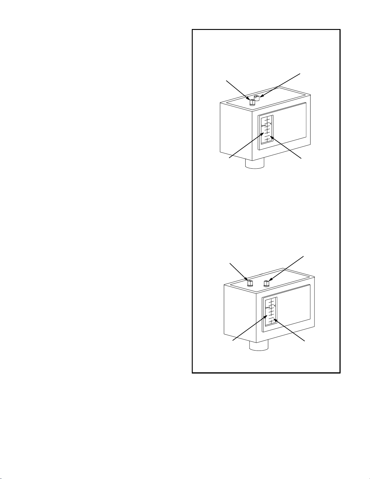
LOW AMBIENT PRESSURE SWITCH S11 DETAIL
RANCO MODEL
ROUND CUT-IN
SQUARE DIFFERENTIAL
ADJUSTMENT KNOB
DIFFERENTIAL
PRESSURE READĆ
OUT ON LEFT
PRESSURE SWITCH IS FACTORY-SET AT 285 PSIG CUT-IN
AND 145 PSIG DIFFERENTIAL (140 PSIG CUT-OUT)
ALCO MODEL
ROUND CUT-IN
ADJUSTMENT
KNOB
SQUARE DIFFERENTIAL
ADJUSTMENT KNOB
ADJUSTMENT
KNOB
CUT-IN PRESSURE
READOUT ON
RIGHT
Page 2
CUT-IN PRESSURE
READOUT ON LEFT
DIFFERENTIAL
PRESSURE READĆ
OUT ON RIGHT
FIGURE 2
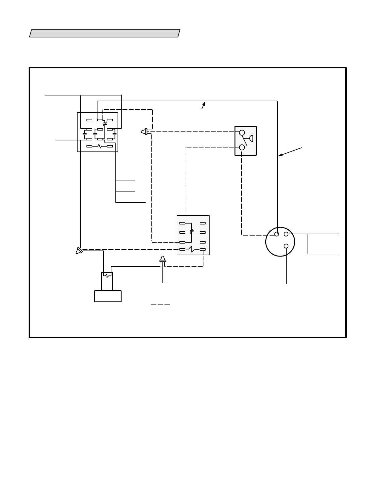
WIRING
Low ambient pressure switch S11 is wired in series with
outdoor fan relay or compressor contactor (single-stage
or speed units).
S11 LOW AMBIENT CONTROL SWITCHES
OUTDOOR FAN DIRECTLY (LINE VOLTAGE)
TO R" LOW
VOLT
TERM STRIP
K4
DEFROST
RELAY
TO O" LOW
VOLT TERM
STRIP
D
2 31
5 64
8
97
TO K1-1
K31 PIN 5
REMOVE THIS WIRE
Low ambient kits are shown with optional arrows on unit
wiring diagrams. If unit wiring diagram is not available or
does not show the low ambient kit, refer to appropriate
wiring diagram in figures 3 through 13 for wiring
connections.
S11
LOW AMBIENT
PRESSURE
SWITCH
1
4
REMOVE THIS
WIRE
COMP C"
L1
REVERSING
VALV E
K58 LOW
AMBIENT
RELAY
31
64
97
TO 24V COM
FIELD WIRING
FACTORY WIRING
SEE SCHEMATIC FIGURE 4
FIGURE 3
B4
OUTDOOR
FAN MOTOR
TO C12 TERM C
TO K1-1
TO C12
TERMINAL F
Page 3
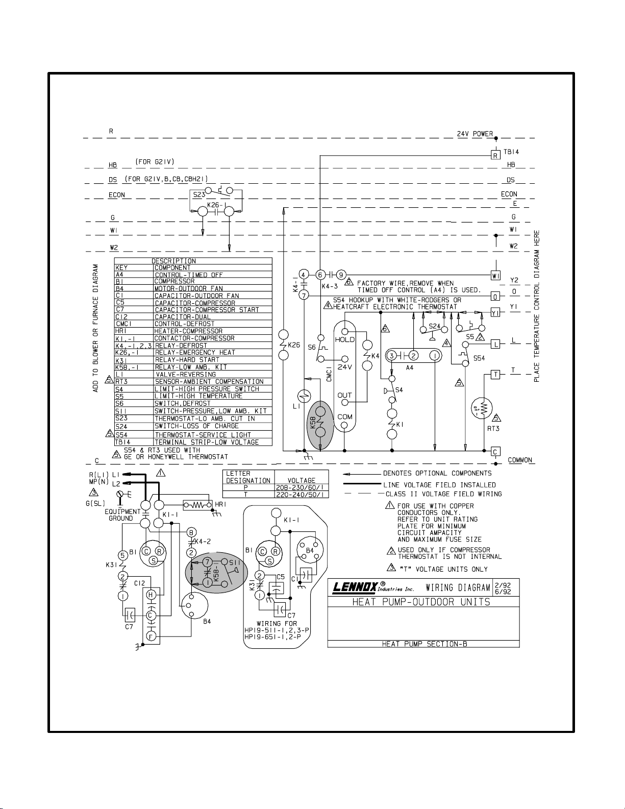
TYPICAL SINGLE-COMPRESSOR HEAT PUMP UNIT WIRING DIAGRAM
(S11 LOW AMBIENT CONTROL SWITCHES OUTDOOR FAN DIRECTLY)
SEE PICTORIAL FIGURE 3
FIGURE 4
Page 4
 Loading...