

Page 1

TABLE OF CONTENTS
DATA PAGE FOR UNIT COMMISSIONING
1.- GENERAL CHARACTERISTICS
1.1.- PHYSICAL DATA
1.2.-FAN SERVICES
1.3.- ELECTRICAL DATA
1.4.- OPERATING LIMITS
1.5.- UNIT DIMENSIONS
1.6.- SIZES OF STANDARD AND OPTIONAL OPENINGS
1.7.- AVAILABLE OPTIONS
2.- INSTALLATION
2.1.- INSTALLATION GUIDELINES
2.2.- UNIT INSTALLATION
2.3.- OPTIONAL TASK PRIOR TO UNIT INSTALLATION:
CHANGING THE POSITION OF BLOWERS AND AIR INTAKE
2.4.- UNIT LOCATION AND WEIGHT DISTRIBUTION
2.5.- INSTALLATION CLEARANCES
2.6.- DRAINS
2.7.- REFRIGERANT CONNECTIONS
2.8.- ELECTRICAL CONNECTIONS
PAGE 2
PAGE
3
3
4
5
6-8
9-10
11
PAGE
12
12
13-14
15
16
16
17-20
21-22
3.- COMMISSIONING AND OPERATION
3.1.- PRELIMINARY CHECKS
3.2.- STEPS TO FOLLOW FOR COMMISSIONING THE UNIT
4.- MAINTENANCE
4.1.- PREVENTIVE MAINTENANCE
4.2.- CORRECTIVE MAINTENANCE
4.3.- FAILURE DIAGNOSIS
1
PAGE
23
24
PAGE
25
26
27
Page 2
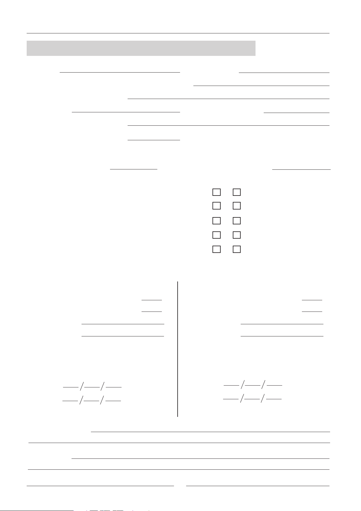
DATA PAGE FOR UNIT COMMISSIONING
UNIT:
CONTROL PANEL IDENTIFICATION CODE
INSTALLATION ADDRESS:
INSTALLER:
INSTALLER ADDRESS:
DATE OF COMMISSIONING:
CHECKS:
SUPPLY VOLTAGE:
UNIT ON SHOCK ABSORBERS
DRAINAGE WITH TRAP
GENERAL POWER SUPPLY CONNECTION
CONTROL PANEL CONNECTION
SERIAL No.:
INSTALLER TEL.:
RATED VOLTAGE OF THE UNIT:
YES NO
COMPRESSOR OIL LEVEL INDICATOR
DATA INPUT:
COOLING CYCLE
Air Intake Temperature to the coil:
Air Output Temperature to the Coil:
High Pressure:
Low Pressure:
ELECTRIC POWER CONSUMPTION
Compressor
Fan
(Amps)
ºC
ºC
HEATING CYCLE
Air Intake Temperature to the coil:
Air Output Temperature to the Coil:
High Pressure:
Low Pressure:
Compressor
Fan
ºC
ºC
Options Installed:
Comments:
2
Page 3
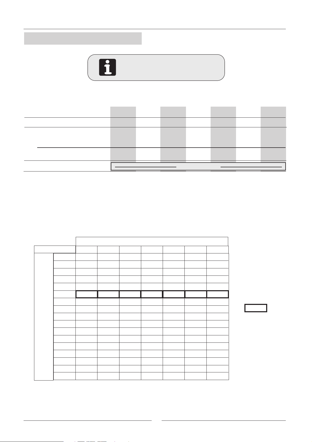
1.- GENERAL CHARACTERISTICS
1.1.- PHYSICAL DATA
KFHA: Heat pump unit R-22
KFCK: Cooling only unit R-407C
KFHK: Heat pump unit R-407C
UNIT MODEL
COMPRESSOR
Nº / Type
10 12 16 22 24 28 30
1 / Scroll 1 / Scroll 1 / Scroll 1 / Scroll
1 / Scroll 1 / Scroll
1 / Scroll
NET WEIGHT
Cooling only units KFC
Heat pump units KFH
REFRIGERANT CHARGE
Kg
Kg
130 135
135 140 185 200 270 285280
180
NITROGEN (*)
195 265 285
275
(*) The units are supplied with nitrogen gas, this must be removed and charge the unit with refrigerant R-22 or R407C, depends on unit model.
(See page 20, to calculate model refrigerant charge)
1.2.- FAN SERVICES
3
m /h
6600 6400 64003500 3400 4950 59000
6490 6300 63003410 3325 4850 5800
6340 6200 62003300 3160 4750 5700
6225 6100 61003190 3075 4625 5600
6100 5980 59803080 2980 4525 5495
5960 5870 58702970 2890 4425 5390
5850 5725 57252840 2790 4325 5280
5710 5600 56002700 2690 4225 5180
5600 5490 54902560 2580 4125 5075
5480 5375 53752410 2400 4040 4975
5350 5250 52502350 3940 4875
5200 51003840 4775
5090 50003750 4675
49504575
48004460
46504350
4500
---
---
---
---
NOMINAL
AIR FLOW
---
---
---
---
---
---
MODELS
10
20
30
40
50
60
70
80
90
100
110
120
130
140
AVAILABLE STATIC PRESSURE Pa.
150
160
10 12 16 22 24 28 30
---
---
---
---
---
---
---
---
---
---
---
---
---
---
---
---
---
AIR FLOW
---
3
3
Page 4
1.- GENERAL CHARACTERISTICS
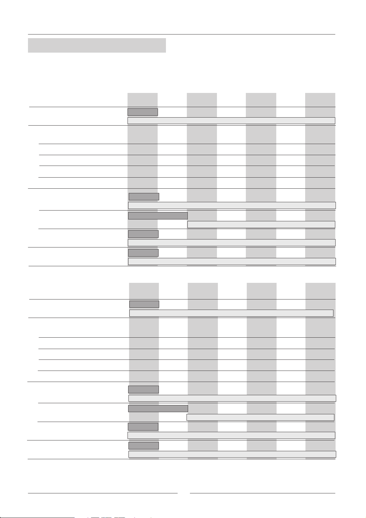
1.3.- ELECTRICAL DATA
UNIT MODELS
Voltage
Rated absorbed power
Compressor (cooling cycle)
Compressor (heating cycle)
Fan
Total power in cooling cycle
Total power in heating cycle
Maximum current
Compressor
Fan
Total current
Start up current
V/f (50 Hz)
Kw
Kw
Kw
Kw
Kw
A
A
A
A
KFHA 12KFHA 10 KFHA 16 KFHA 22 KFHA 24 KFHA 28
230V/ 1Ph
230V-400V/ 3Ph
2,60 3,41
2,03 2,54
0,52 0,52 1,10 1,60 1,60 1,601,60
3,12
2,55 3,06 3,50 5,30
18,6
16,7/7,2 19,3/8,7 19,9/11,5 22,4/12,9 25,3/14,6 36,5/21,028,5/16,3
3,1 3,1
21,7
99
3,93
22,4/11,819,8/10,3
4,11 5,02 5,85 8,837,41
2,94 3,70 4,85 6,485,48
5,21 6,62
4,8/2,8 7,4/4,3 8,1/4,7 8,1/4,7 8,1/4,7
7,45 10,43
6,45 8,08
9,01
7,08
KFHA 30
44,6/25,736,6/21,033,4/19,329,8/17,224,7/14,3
177/109183/83181/109193/110148/77102/5496/47
UNIT MODELS
Voltage
Rated absorbed power
Compressor (Cooling cycle)
Compressor (heating cycle)
Fan
Total power in Cooling cycle
Total power in heating cycle
Maximum current
Compressor
Fan
Total Current
Start up current
V/f (50 Hz)
Kw
Kw
Kw
Kw
Kw
A
A
A
A
KFCK 10
KFHK 10
230V/ 1Ph
2,79 3,68
2,26
0,52 0,52 1,10 1,60 1,60 1,601,60
3,31
2,78 3,73 4,70 5,44
18,6
16,7/7,2 19,3/8,7 19,9/11,5 22,4/12,9 25,3/14,6 36,5/21,028,5/16,3
3,1 3,1
21,7
99
KFCK 12
KFHK 12
3,21
4,20
22,4/11,819,8/10,3
KFCK 16
KFHK 16
4,41 5,20 6,05 9,257,43
3,60
5,51 6,80
4,8/2,8 7,4/4,3 8,1/4,7 8,1/4,7 8,1/4,7
KFCK 22
KFHK 22
230V-400V/ 3Ph
3,84 5,65 7,376,25
KFCK 24
KFHK 24
7,65 10,85
7,25 8,97
KFCK 28
KFHK 28
9,03
7,85
KFCK 30
KFHK 30
44,6/25,736,6/21,033,4/19,329,8/17,224,7/14,3
177/109183/83181/109193/110148/77102/5496/47
4
Page 5
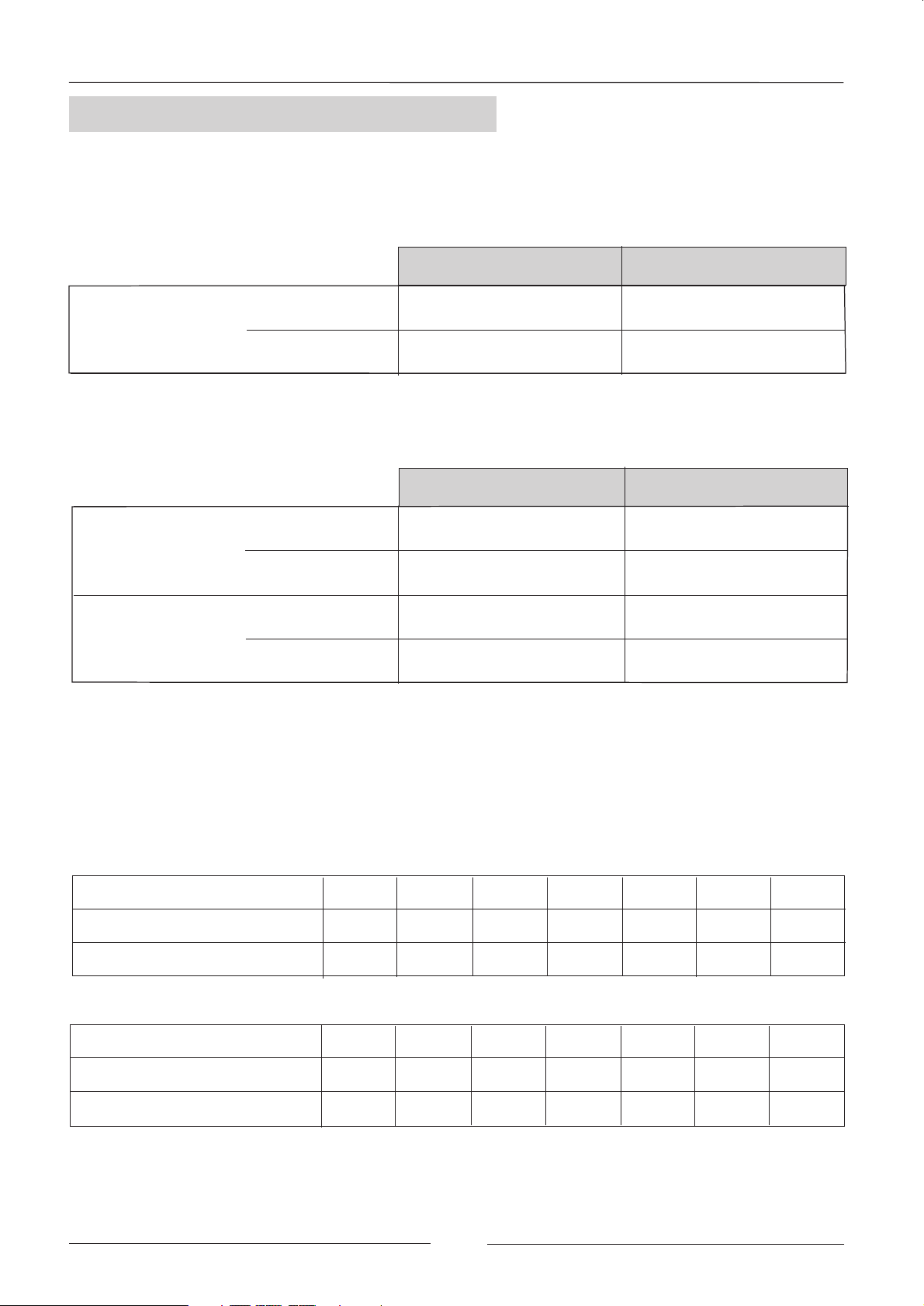
1.- GENERAL CHARACTERISTICS
1.4.- OPERATING LIMITS
(To install with LFXO / LFCK / LFHK / LFHA indoor unit)
OPERATING LIMITS FOR (COOLING ONLY) UNITS
MAXIMUM TEMPERATURES MINIMUM TEMPERATURES
COOLING CYCLE
OPERATION
INDOOR
TEMPERATURE
OUTDOOR
TEMPERATURE
32º C DB / 23ºC WB
DEPENDING ON MODEL
(TABLE 1)
21º C DB / 15ºC WB
0º C (MODELS 22/24/28/30)
19º C (MODELS 10/12/16) (*)
(*) With condensation pressure control (optional), 0 ºC minimum outdoor operating temperature
OPERATING LIMITS FOR (heating PUMP) UNITS
MAXIMUM TEMPERATURES MINIMUM TEMPERATURES
COOLING CYCLE
OPERATION
heating CYCLE
OPERATION
INDOOR
TEMPERATURE
OUTDOOR
TEMPERATURE
INDOOR
TEMPERATURE
OUTDOOR
TEMPERATURE
32º C DB / 23ºC WB
DEPENDING ON MODEL
(TABLE 1)
27º C DB
24º C DB / 18ºC WB
21º C DB / 15ºC WB
0º C (MODELS 22/24/28/30)
19º C (MODELS 10/12/16) (*)
21º C BD / 15ºC WB
-10º C DB / -11ºC WB
(*) With condensation pressure control (optional), 0 ºC minimum outdoor operating temperature
DB.- Dry Bulb Temperature
WB.- Wet Bulb Temperature
TABLE 1-COOLING CYCLE MAXIMUM OUTDOOR OPERATING TEMPERATURES
MODELS WITH REFRIGERANT R-407C
MODELS
With rated outdoor flow
With minimum outdoor flow
MODELS WITH REFRIGERANT R-22
MODELS
With rated outdoor flow
With minimum outdoor flow
10 12 16 22 24 28 30
45
43
43
43
44
41
45
41
46
42
42
39
41
38
10 12 16 22 24 28 30
48
46
48
45
47
45
5
48
46
48
44
46
42
44
40
Page 6
1.- GENERAL CHARACTERISTICS
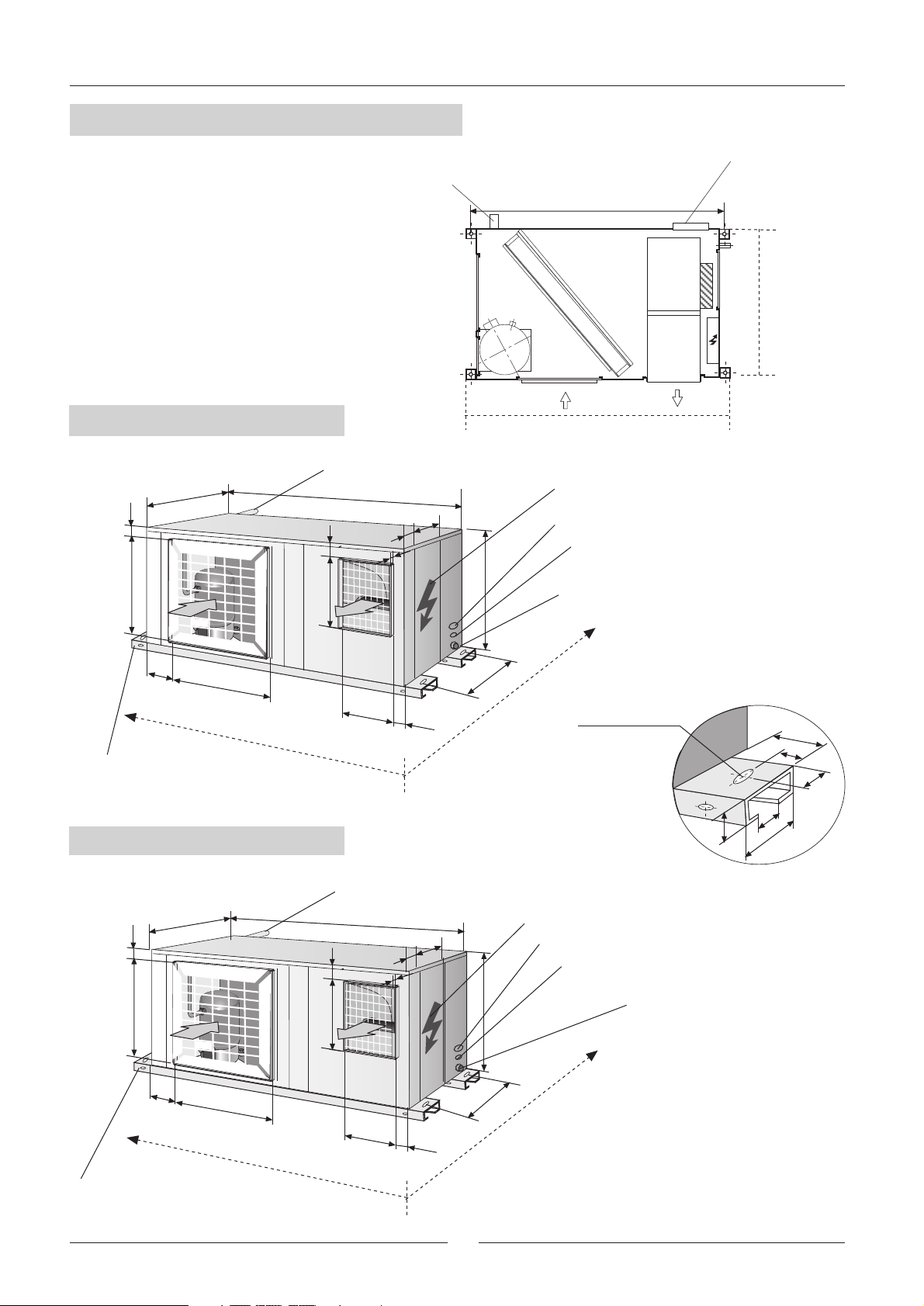
1.5.- UNIT DIMENSIONS
Connection pipes
Distance between holes
MODELS 10-12: 1300 mm
MODEL 16 = 1350 mm
Indoor unit
electrical
connection
SIDE B
UNITES MODEL 10-12
820
32
425
184
452
SIDE A
Unit anchor
support
UNIT MODEL 16
Connection pipes
1250
333
6
27
303
349
25
123
495
711,6
SIDE B
SIDE A
Electrical box
Power supply connection
Control panel connection
Drainage
outside thread
3/4'' Male
20 x12
Oval hole
25
50
25
40
60
80
32
Unit anchor
support
500
249
830
422
SIDE A
Connection pipes
1300
6
27
355
25
324
333
123
721,6
6
595
Detail drawing of
unit anchor support
Electrical box
Power supply connection
Control panel connection
Drainage
outside thread
3/4'' Male
SIDE B
Page 7
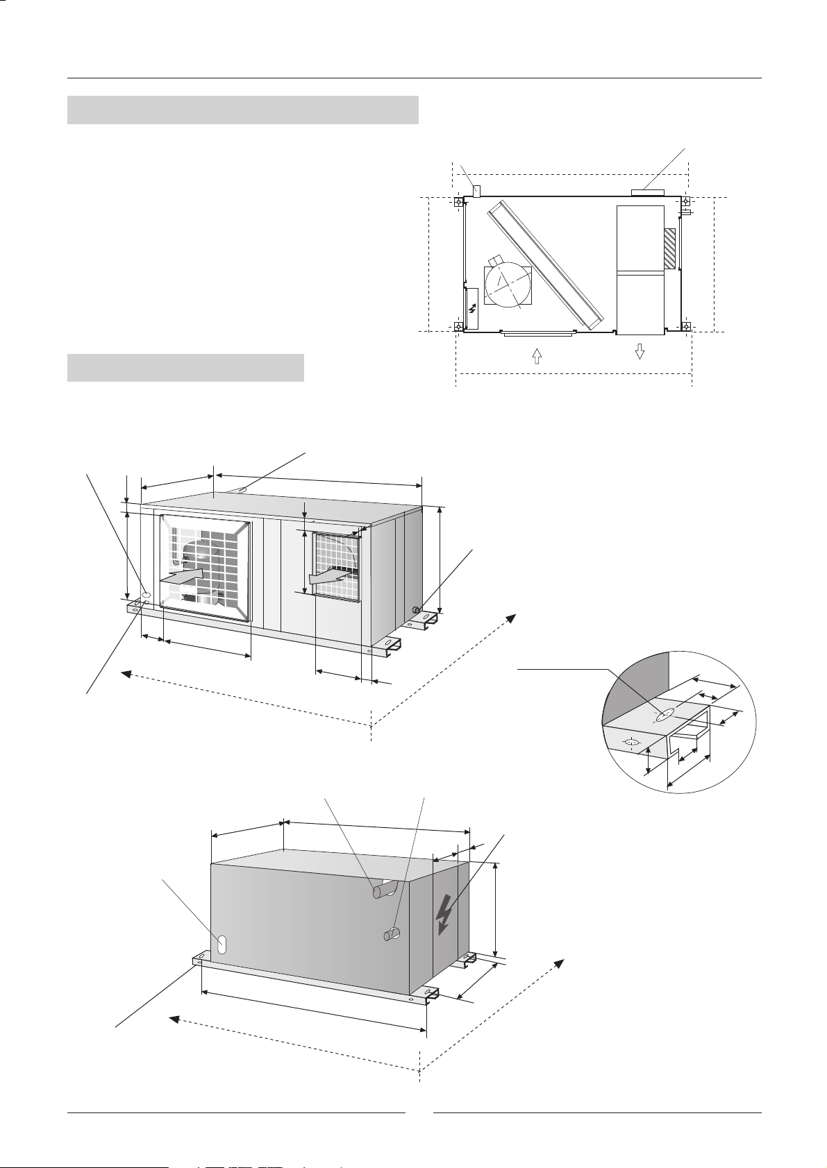
1.- GENERAL CHARACTERISTICS
1.5.- UNIT DIMENSIONS
Connection pipes
Indoor unit
electrical
connection
SIDE C
UNIT MODEL 22
Power supply
connection
36,5
497
Control panel
connection
262
900
462
SIDE A
Connection pipes
1450
47
25
355
324
92
SIDE D
595
SIDE B
SIDE B
SIDE A
Drainage
outside thread
3/4'' Male
20 x12
Oval hole
50
25
40
Indoor unit
electrical
connection
Unit anchor
support
Gas pipe
900
Distance between holes1500
SIDE C
1450
Liquid pipe
300
7
Electrical box
30
595
791
SIDE D
25
60
80
Detail drawing of
unit anchor support
Page 8
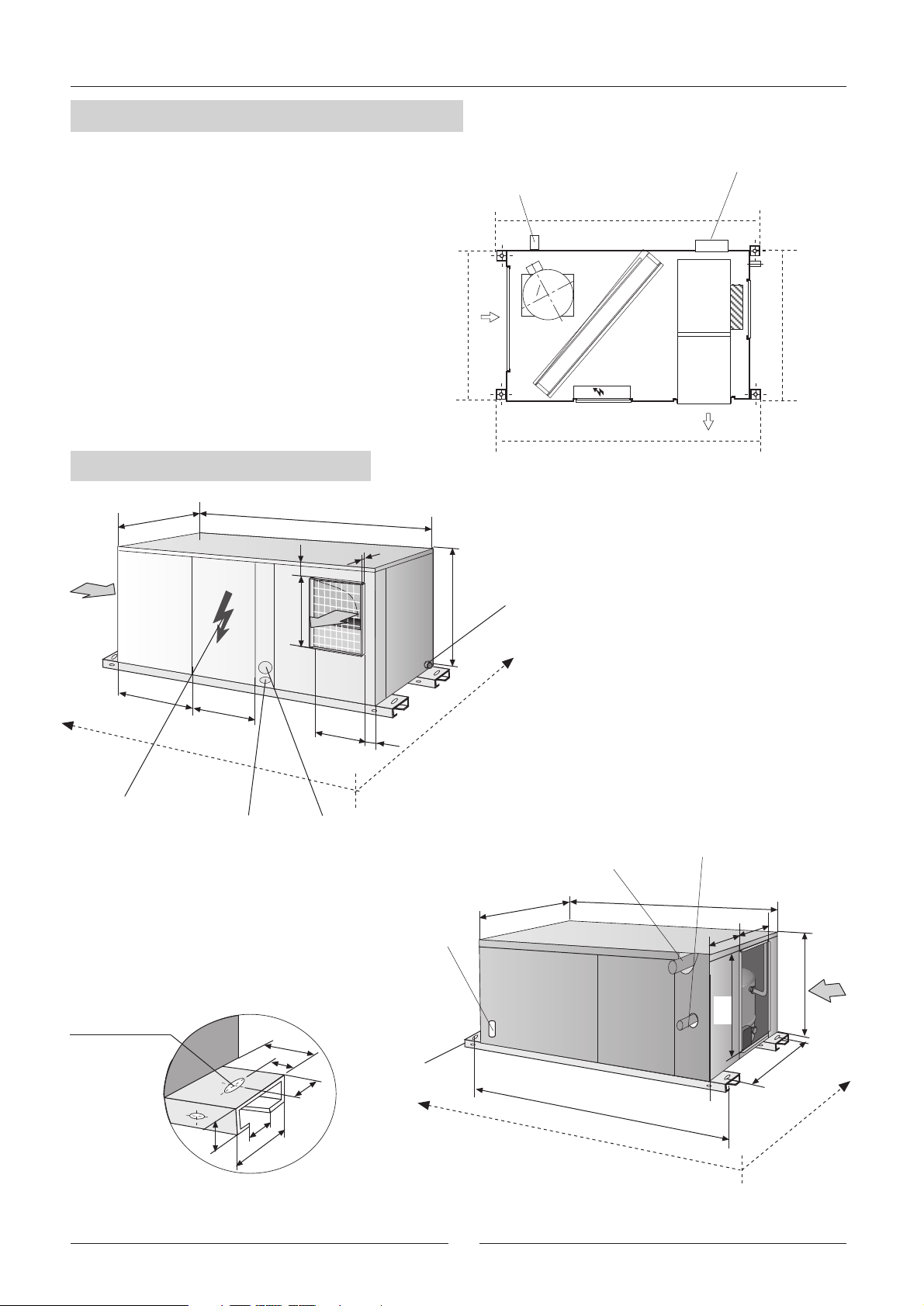
1.- GENERAL CHARACTERISTICS
1.5.- UNIT DIMENSIONS
UNITES MODEL 24-28-30
SIDE D
Connection pipes
Indoor unit
electrical
connection
SIDE C
SIDE B
SIDE A
1025
Electrical box
490
SIDE A
398
Control panel
connection
1500
25
76
355
410
Power supply
connection
103
Indoor unit
electrical
connection
645
SIDE B
Drainage
outside thread
3/4'' Male
Gas pipe
1025
1500
Liquid pipe
677
124
20 x12
Oval hole
50
25
40
25
60
80
Detail drawing of
unit anchor support
Unit anchor
support
Distance between holes1550
8
645
537
916
SIDE C
SIDE D
Page 9
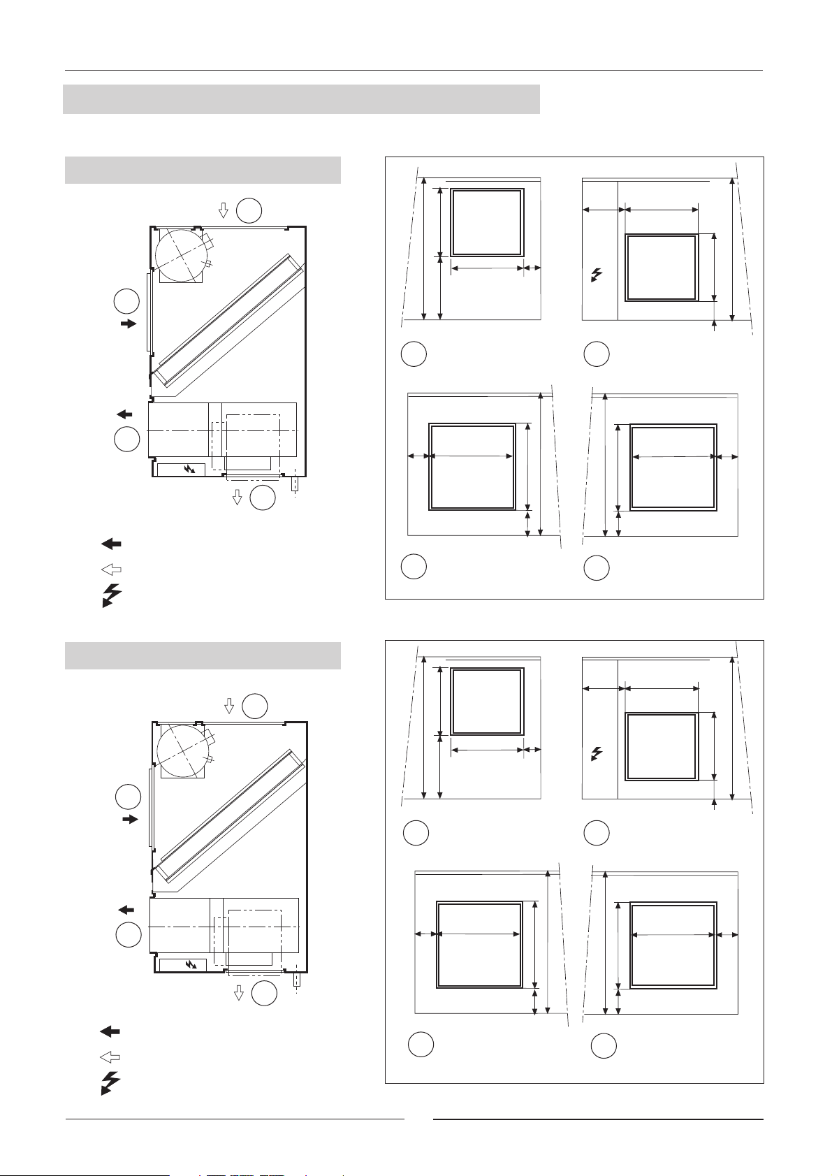
1.- GENERAL CHARACTERISTICS
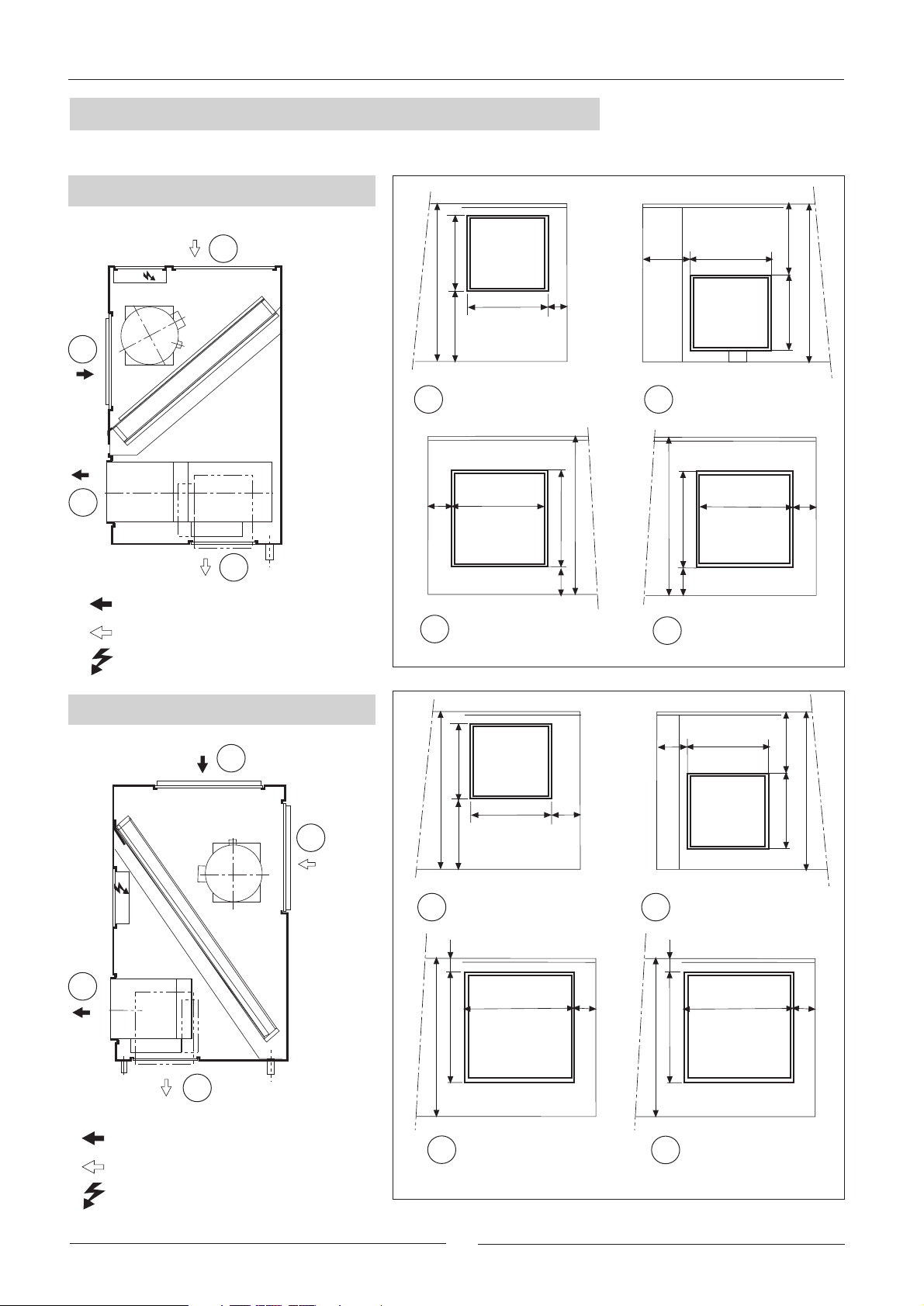
1.6.- UNIT OPENING SIZES
UNITS MODELS 10-12
B1
B0
A0
COMPRESSOR
COIL
FAN
C.E.
A1
STANDARD CONFIGURATION
OPTIONAL CONFIGURATION
ELECTRICAL BOX
B0
303
495
170
STANDARD
BLOWER
OPENING
452184
STANDARD
EXTRACTOR
OPENING
349
123
425
43
495
368
C.E.
A1A0
B1
OPTIONAL
BLOWER
OPENING
495
425
43
OPTIONAL
EXTRACTOR
OPENING
349
452
495
303
38
269
UNIT MODEL 16
COMPRESSOR
B0
A0
C.E.
STANDARD CONFIGURATION
OPTIONAL CONFIGURATION
ELECTRICAL BOX
COIL
B1
FAN
A1
355
595
213
B0
324
123
STANDARD
BLOWER
OPENING
422249
STANDARD
EXTRACTOR
OPENING
500
63
595
428
C.E.
A1A0
B1
595
500
63
324
OPTIONAL
BLOWER
OPENING
422
OPTIONAL
EXTRACTOR
OPENING
595
355
58
304
9
Page 10
1.- GENERAL CHARACTERISTICS
1.6.- UNIT OPENING SIZES
UNIT MODEL 22
B0
A0
B1
C.E.
COMPRESSOR
COIL
FAN
A1
STANDARD CONFIGURATION
OPTIONAL CONFIGURATION
ELECTRICAL BOX
595
B0
355
324
193
STANDARD
BLOWER
OPENING
462262
STANDARD
EXTRACTOR
92
497
61
OPENING
595
391,5
A1A0
B1
595
497
61
324
OPTIONAL
BLOWER
OPENING
462
OPTIONAL
EXTRACTOR
OPENING
193
595
355
384
UNITS MODELS 24-28-30
B0
COMPRESSOR
C.E.
COIL
A0
FAN
A1
STANDARD CONFIGURATION
OPTIONAL CONFIGURATION
ELECTRICAL BOX
B1
645
645
B0
355
214
STANDARD
40
537
STANDARD
EXTRACTOR
410
BLOWER
OPENING
677
OPENING
103
222
103
A1A0
40
537
645
B1
410
OPTIONAL
BLOWER
OPENING
677
OPTIONAL
EXTRACTOR
OPENING
214
355
645
174
10
Page 11

1.- GENERAL CHARACTERISTICS
1.7.- AVAILABLE OPTIONS
MAIN SWITCH
The main switch is located on the access panel to the electrical box in such a way that the unit is disconnected
when the panel is opened.
(Refer to the size diagram on pages 7 to 10 to see the position of the electrical box access panel).
Check to make sure that the main switch is large enough to handle the current for the unit if electric heaters are
installed.
PHASE SEQUENCER (THREE-PHASE UNIT)
The phase sequencer is located in the electrical box in the outdoor section, thus assuring that the unit will not
begin operation while the phase connection of the compressor is not correct. Should this occur, then just switch
two phase connections.
ON/OFF CONDENSATION PRESSURE CONTROL (MODELS 10-12-16)
The condensation pressure control consists of a pressure switch, which starts and stops the outdoor fan regulating
the condensation temperature, thus the unit will be able to operate in the cooling cycle when the outdoor
temperature is below 19ºC.
HOT GAS BYPASS VALVE
The purpose of the BYPASS valve is to make it possible for the unit to operate at low outdoor temperatures (under
0°C), to be used in cooling-only and head-pump units.
It regulates the capacity of the compressor by injecting hot gas from the compressor discharge side to the
evaporator.
CRANKCASE HEATER (COOLING-ONLY UNITS)
When the unit is operating at low outdoor temperatures it is advisable to fit a crankcase heater.
The purpose of the heater is to keep the oil in the compressor at the correct temperature while the compressor is
stopped so that it can be properly lubricated when started again.
SOUND MUFFLER
Available for models 16, 22, 24, 28, 30.
Field assembled, designed to be installed at the extractor
opening of the outdoor unit in order to reduce noise, particularly
when the outdoor unit is installed without ducts, free discharge.
This kit contains the sound muffler and adapter parts for fixing
it to the unit.
OUTDOOR MOUNTING KIT
Field assembly.
This kit is comprised of an air filter and grille for outdoor air
intake which should be installed on the suction side of the
outdoor unit, and the anti-rain hood which should be installed
on the discharge side of the outdoor fan.
OUTDOOR AIR FILTER KIT
Field assembly.
The outdoor air filter should be installed on the outdoor air inlet
of the outdoor unit and is recommended when working in
heavily contaminated areas that may soil or clog the coil.
Air filter
Outdoor air intake
Sound muffler
Adapter parts
Anti-rain hood
11
Page 12

2.- INSTALLATION
2.1.- PRELIMINARY PREPARATIONS
All INSTALLATION, SERVICE and MAINTENANCE operations
must be carried out by QUALIFIED PERSONNEL.
The unit must be transported in a HORIZONTAL POSITION on its metal bedplate profiles and TRANSPORTATION
BLOCKS. Any other position may cause serious damage to the machine. When the unit is received, it should be
checked to assure that there are no bumps or other damage, following the instructions on the packaging. If there
is damage, the unit may be rejected by notifying the LENNOX Distribution Department and reporting why the
machine is unacceptable on the transport agent’s delivery notice. Any later complaint or claim made to the
LENNOX Distribution Department, for this type of anomaly, cannot be considered under the Guarantee.
Sufficient space must be allowed to facilitate placement of the unit. The unit may be mounted outdoors. There
should be NO possibility of flooding if floor mounted.
When positioning the unit, be sure that the Rating Plate will always be visible since this
data will be necessary to assure proper maintenance.
The units are designed to be installed with ducts, calculated by qualified technical staff. The joints to be used
between ducts and the openings to the unit should be Elastic Joints. Avoid the use of BYPASS joints between the
extraction air and input air in both the outdoor and indoor sections. The structure where the unit is placed must
be able to support the weight of the unit during operation.
2.2.- UNIT RECEPTION
All the units have Metal Bedplate Profiles and Wooden Blocks for transportation.
These wooden blocks must be removed when positioning the unit in its final position.
PLACEMENT OF THE BEDPLATE
AND TRANSPORTATION BLOCKS
Bedplate profile
Wood
block
How to hoist the unit
If unloading and placement require the use of a
crane, then secure the suspension cables as
shown in the figure.
To remove the transportation blocks,
remove the screw and slide the block along the metal profile.
Securing
screw
Wood
block
Use
separators
12
Page 13

2.- INSTALLATION
2.3.- OPTIONAL OPERATIONS PRIOR TO UNIT INSTALLATION:
CHANGE IN THE POSITION OF BLOWERS AND AIR INTAKE
UNITS MODELS 10-12-16-22
STANDARD AIR INTAKE AND BLOWERS OPTIONAL AIR INTAKE AND BLOWERS
Service
Panel
Intake
Opening
Intake
Opening
B1
B0
Extension
Collar
Service
Panel
A0
Motor
Fan-motor assembly
Blower Panel
with Opening
Service
Panel
BLOWER:
From the position to the position
A0
1) Remove the ceiling of the unit, the Blower Panel with Opening and the Service Panel.
2) Remove the motor-fan assembly from the unit unscrewing the supports from the base, and throwing away the
extension collar, if there is one.
3) Unscrew the supports that have been left on the fan-motor assembly.
4) Turn the fan-motor assembly to its new position 90º horizontally and 180º on its shaft. The motor should now
be accessible from the Service Panel in this new position.
Motor
A1
Fan-motor assembly
A1
Blower Panel
with Opening
5) Screw down the fan-motor assembly in its new position using the supports.
6) Assemble the Blower Panel with Opening and the Service Panel in its new position, taking special care with the
weather striping.
INLET:
From the position to the position
B0
B1
1) Remove the Intake Opening and the Service Panel.
2) Switch the position of the Opening and Service Panels.
SEE LOCATIONS AND SIZES FOR THE OPENINGS IN THEIR STANDARD AND OPTIONAL
POSITIONS ON THE GENERAL MEASUREMENT DRAWINGS.
13
Page 14

2.- INSTALLATION
2.3.- OPTIONAL OPERATIONS PRIOR TO UNIT INSTALLATION:
CHANGE IN THE POSITION OF BLOWERS AND AIR INTAKE
UNITS MODELS 24-28-30
STANDARD AIR INTAKE AND BLOWERS OPTIONAL AIR INTAKE AND BLOWERS
Service
Panel
Extension
Collar
B0
A0
Blower Panel
with Opening
Service
Panel
BLOWER:
From the position to the position
Motor
Fan-motor assembly
A0
A1
Service
Panel
Motor
Blower Panel
with Opening
Intake
Opening
D'
B1
Fan-motor
assembly
A1
1) Remove the ceiling of the unit, the Blower Panel with Opening and the Service Panel.
2) Remove the motor-fan assembly from the unit unscrewing the supports from the base, and throwing away the
extension collar, if there is one.
3) Unscrew the supports that have been left on the fan-motor assembly.
4) Turn the fan-motor assembly to its new position 90º horizontally and 180º on its shaft. The motor should now
be accessible from the Service Panel in this new position.
5) Screw down the fan-motor assembly in its new position using the supports.
6) Assemble the Blower Panel with Opening and the Service Panel in its new position, taking special care with the
weather striping.
INLET:
From the position to the position
1) Remove the Intake Opening and the Service Panel.
2) Switch the position of the Opening and Service Panels.
SEE LOCATIONS AND SIZES FOR THE OPENINGS IN THEIR STANDARD AND OPTIONAL
POSITIONS ON THE GENERAL MEASUREMENT DRAWINGS.
B0
B1
14
Page 15

2.- INSTALLATION
2.4.- UNIT LOCATION AND WEIGHT DISTRIBUTION
The bedplate is made up of three galvanized metal channels, capable of withstanding the weight of the units
whether hung from the ceiling or mounted on the floor.
If the unit is floor mounted, then the profiles should be isolated with shock absorbing material such as anti-vibration
or pads. If used, consult the weight distribution table below to make the correct selection. Keep in mind that fans
rotate at approximately 850 rpm.
If the unit is hung, M-10 threaded rods should be used along with shock absorbing ceiling supports.
UNIT HUNG WITH RODS
UNIT INSTALLED ON SHOCK ABSORBERS
Ceiling supports
(shock absorbers)
Floor supports
(shock absorbers)
Y
MODELS 10-12-16-22
B
Coil
YG
Comp.
A
XG
TABLE 1:
WEIGHT DISTRIBUTION
AND CENTRE OF
GRAVITY COORDINATES
G
FAN
E
X
F
G POINT: Centre of gravity
Point
WEIGHT DISTRIBUTION (Kg)
Model
10
12
A B E F Total
40 35 20 40 135
40 45 20 35 140
YG
Y
B
MODELS 24-28-30
Comp.
G
E
Coil
FAN
X
F
A
XG
CENTRE OF GRAVITY
COORDINATES (G)
(mm.)
XG
550
505
YG
340
380
16
22
24
28
30
55 50 35 45 185
55 50 45 50 200
75 70 75 50 270
80 75 75 50 280
80 80 75 50 285
15
570
670
705
660
645
375
425
550
550
550
Page 16

2.- INSTALLATION
2.5.- INSTALLATION CLEARANCES
Clearance around the unit for service and maintenance.
1 metro
1 metro
1 metro
1 metro
Consult other options for outdoor mounting or changes in position of the air return duct if the unit
is to be hung.
2.6.- DRAINS
All heat Pump units have a ¾” steel threaded drain pipe welded to the condensation tray.
Drain pipe
2%
2%
Trap
One PVC drain trap is supplied with the the heat pump units.
Connect the trap to the drain pipe on the unit and mount the drain pipe with at least a 2% incline from the trap.
Also slightly tip the unit (2%) toward the drainage side. Check that the condensation trays are clean and free from
dirt and other debris from the works and that water drains correctly.
16
Page 17

2.- INSTALLATION
2.7.-REFRIGERANT CONNECTIONS
The units are supplied with gas and liquid lines sealed with copper covers, and located 60mm from casing
60
Cupper cover
Brazing
The units are supplied with nitrogen gas, this must be removed
1º Remove the nitrogen gas, through the high and low ¼” service ports locate inside, from both indoor and outdoor
units.
2ª Remove the covers from connecting lines.
3ª Braze the piping connection lines. Refer to installation manual to select the diameter of the lines.
(When brazing refrigerant pipes, is necessary to supply nitrogen gas through the service ports into the pipes to
remove the air)
4º Leak test:
- Add nitrogen gas and check 5 kg/cm2 pressure has been reached, and verify there are not leaks in the circuit
or brazing, applying soapy water on pipes, because the leaks cause soapy water to form bubbles.
To detect small leaks proceed as follow:
Add nitrogen gas and check 32 kg/cm2 pressure has been reached, there is not leak if pressure remain the same
at least during 24 hours and final pressure is not less than 10% from the initial pressure.
5º Be sure gas line is isolated
6º Vacuuming.
Remove the nitrogen gas, connect the gauge manifold and vacuum pump to both liquid and gas line, fully open
the valve of the gauge manifold and switch on the vacuum pump. Check to make sure the gauge shows a pressure
level of –750mm Hg, after a level of –750mm Hg is reached, keep on the vacuum pump at least during an hour.
7º Refrigerant charge
- Refer to installation manual to verify amount and type of refrigerant which must be charged, and the total
amount to be added must be calculated considering the refrigerant charge of the unit, and also the length and sizes
of the refrigerant piping.
- Disconnect the vacuum pump and connect to the refrigerant-charging cylinder. Open the charging cylinder
and purge the air from the hose at the gauge manifold.
- Set up the amount of additional refrigerant on the weighing scale, open the high pressure (liquid) and low
pressure side (suction) of the gauge valve to start the process of refrigerant from outdoor unit. If the total amount
of refrigerant charge have not been reached, because balance pressure, turn off the high side of the gauge manifold,
turn on the unit, and add slowly though low side of the gauge the remain amount of the refrigerant charge needed.
(With R-407C refrigerant, the charging cylinder must be on horizontal position and it is important to charge
in liquid state)
Close the sides of gauge valve from service port of the unit, put the covers on service ports. Then the unit is ready
to work.
Gas
Terminal block
Líquid
and then proceed as follow:
Service ports
During installation operations, keep gas and liquid pipes covered, in order to provent humidity
and dirt, get into them.
Take special concern about refrigerant pipes are isolated.
17
Page 18

2.- INSTALLATION
2.7.-REFRIGERANT CONNECTIONS
To locate the outdoor and the indoor units, refer to the following information:
2%
A,B,C : Unit positions
L : Total length
1 = Gas line
2 = Líquid line
INDOOR UNIT
OUTDOOR UNIT
OUTDOOR UNIT
2
2%
B
1
A
INDOOR UNIT
1
2%
2
L
L
OUTDOOR UNIT
2%
2%
2
INDOOR UNIT
1
L
C
POSITION A : A syphon suction must be installed on the vertical line of the gas line, and syphons must be
installed every 8 meters upward.
POSITION B : Tip the lines toward the outdoor unit. Make special atention to line length longer than 10m
POSITION C : Install a syphon at the base of the vertical line, no more syphons are necessary.
TABLE 2: REFRIGERANT LINES SELECTION
UNIT - MODEL
REFRIGERANT LINES
Total line length
0 to 10 m.
10 to 30 m.
30 to 50 m.
Líquid
Gas
Líquid
Gas
Líquid
3/8"
3/4"
3/8"
3/4"
1/2"
7/8"
5/8"
7/8"
5/8"3/8" 3/8" 5/8"
7/8"7/8"
7/8"
11/8"
1/2" 1/2" 5/8" 5/8"
24 28 302210 12 16
5/8"
11/8"
5/8"
11/8"
5/8''
11/8"
5/8''
11/8"
5/8''
11/8"
3/4''
13/8"
3/4'' 3/4'' 3/4''
11/8"7/8"
7/8"
13/8" 13/8" 13/8"
5/8" 5/8'' 5/8''5/8"3/8" 3/8" 1/2"
11/8" 11/8" 11/8"7/8"3/4"
Unit connections
Maximum vertical line length (m.)
Maximum number of bends
Gas
Líquid
Gas
7/8" 11/8"
3/4"
15 15 15 15 15 15 15
12 12 12 12 12 12 12
- THE GAS LINE ALWAYS MUST BE INSULATED
- THE HORIZONTAL LINES MUST BE TIPED AT LEAST 2% TOWARD THE OUTDOOR UNIT
- THE MAXIMUM SPEED INSIDE LINES, NOT SHOULD BE MORE THAN 15 m/seg.
For other positions and lines lengths between 30 and 50m or longer , consult the commercial
- technical department, the following data will be obtained from that estimation.
Pipe dimensions, Syphon suction, Isolations, Refrigerant load, Line lengths
18
Page 19

2.- INSTALLATION
2.7.-REFRIGERANT CONNECTIONS
PRECAUTIONS TO BE TAKEN IN THE USE OF R-407C Refrigerant
If R-407C Refrigerant is used in the unit, the following precautions characteristic of this gas should
be taken:
- The Vacuum Pump must have a Check Valve or Solenoid Valve.
- Pressure Gauges and Hoses for the exclusive use with R-407C Refrigerant should be used.
- The charge should be carried out in the Liquid Phase.
- Always use scales to weight-in charge- Use the Leak Detector exclusive for R-407C Refrigerant.
- Do not use mineral oil, nonly ynthetic oil to ream, expand or make connections.
- Keep pipes wcappedbefore using them and be very thorough about any possible dirt (dust, filings,
burrs, etc.).
- When there is a leak, gather what is left of the charge, create a vacuum in the unit and completely
recharge with new R-407C Refrigerant.
- WBrazingshould always be carried out in a nitrogen atmosphere.
- Reamers should always be well sharpened.
19
Page 20

2.- INSTALLATION
2.7.-REFRIGERANT CONNECTIONS
TABLE 3: WEIGHT OF REFRIGERANT PER METER LINE
FROM 0 TO 10M FROM 10 TO 30M FROM 30 TO 50M
Suction Liquid Suction Liquid Suction Liquid
gr/m gr/m gr/m
MODEL 10
MODEL 12
MODEL 16
MODEL 22
MODEL 24
MODEL 28
MODEL 30
TABLE 4: CHARGE OF REFRIGERANT FOR OUTDOOR UNIT + INDOOR UNIT LF
3/4"
3/4"
7/8"
7/8"
1-1/8"
1-1/8"
1-1/8"
UNIT MODELS
Charge of refrigerant R-22
for 0 meters of line.
UNIT MODELS
Charge of refrigerant R-407C
for 0 meters of line.
3/8"
3/8"
1/2"
5/8"
5/8"
5/8"
5/8"
gr.
gr.
50
50
95
150
155
155
155
KFHA 10
+
LFXO 10
2.900 3.100 3.900 5.400 8.400 8.7008.600
KFCK 10
+
LFXO 10
2.240 2.560 3.550 5.000
7/8"
7/8"
7/8"
1-1/8"
1-1/8"
1-1/8"
1-3/8"
KFHA 12
+
LFXO 12
KFCK 12
+
LFXO 12
3/8"
3/8"
5/8"
5/8"
5/8"
5/8"
3/4"
KFHA 16
+
LFXO 16
KFCK 16
+
LFXO 16
50
50
150
155
155
155
235
KFHA 22
+
LFHA 22
KFCK 22
+
LFCK 22
KFHA 24
LFHA 24
KFCK 24
LFCK 24
7/8"
7/8"
1-1/8"
1-1/8"
1-3/8"
1-3/8"
1-3/8"
KFHA 28
+
LFHA 28
KFCK 28
+
LFCK 28
--- 7.000---
1/2"
1/2"
5/8"
5/8"
3/4"
3/4"
3/4"
+
+
95
95
155
155
235
235
235
KFHA 30
+
LFHA 30
KFCK 30
+
LFCK 30
UNIT MODELS
Charge of refrigerant R-407C
for 0 meters of line.
CHARGE OF REFRIGERANT FOR THE SET:
EXAMPLE:
To install a KFHK 16 + LFXO 16 set, with a 22m refrigerant line lenght between outdoor and indoor unit, then the
refrigerant charge must be calculated as follow:
1º Type of refrigerant R-22 or R-407C, in this case, R-407C .
2º The TABLE 2 shows, that for 22m of line legth between indoor unit and outdoor unit, the line sizes are, liquid
5/8", and gas 7/8".
3º TABLE 3 shows, for line sizes of 5/8"-7/8", the charge per meter line is: 150 gr/m.
4º TABLE 4 shows, charge of refrigerant for the set with 0m of line leght is 4000gr.
5º To determinate the charge of the set:
Add charge of the refrigerant lines + charge of refrigerant indoor unit and outdoor unit
KFHK 10
+
LFXO 10
2.620 2.920 4.000 5.500 7.500 8.2008.000
gr.
KFHK 12
+
LFXO 12
KFHK 16
+
LFXO 16
KFHK 22
+
LFHK 22
KFHK 24
+
LFHK 24
KFHK 28
+
LFHK 28
KFHK 30
+
LFHK 30
Total charge for the set: (150 gr/m) x 22m + 4.000 gr = 4.300 gr
20
Page 21

2.- INSTALLATION
2.8.- ELECTRICAL CONNECTION
- BEFORE MAKING ANY ELECTRICAL CONNECTIONS, BE SURE THAT ALL CIRCUIT BREAKERS ARE
OPEN.
- IN ORDER TO CARRY OUT THE ELECTRICAL CONNECTIONS, FOLLOW THE ELECTRICAL DIAGRAM
SUPPLIED WITH THE UNIT.
Power Supply
1
2
Connection indoor-outdoor unit
Electrical heater power supply
3
Connection to the Control Panel.
4
TABLE 6: CABLES SELECTION
POWER SUPPLY
230V SINGLE PHASE
UNITS
PE N L
1N ~ 230V - 50 Hz + PE
X1
UNIT
MODEL
10
POWER SUPPLY
230V THREE-PHASE
UNITS
PE L1 L2
L3
UNIT
MODEL
X1
10
12
16
3 ~ 230V - 50 Hz + PE
22
24
28
30
No. OF CABLES x SECTION (mm )
1
Power supply
WITHOUT
electrical heater.
3 x 4 2 x 13 x 16
1 1
Power supply
WITHOUT
electrical heater.
4 x 4
4 x 4
4 x 6
4 x 10
4 x 10
4 x 10
4 x 16
Outdoor
Indoor
Section
2
Section
3
1 2
Power supply
WITH electrical
heater.
Connection
outdoor-indoor unit
WITHOUT
electrical heater.
5 x 1,5
No. OF CABLES x SECTION (mm )
2
Power supply
WITH electrical
heater.
4 x 10
4 x 10
4 x 16
4 x 16
4 x 25
4 x 25
4 x 25
Connection
outdoor-indoor unit
WITHOUT
electrical heater.
5 x 1,5
5 x 1,5
4 x 2,5 + 2 x 1
4 x 2,5 + 2 x 1
4 x 2,5 + 2 x 1
4 x 2,5 + 2 x 1
4 x 2,5 + 2 x 1
3
Electrical heater
power supply
3 x 4 + 2 x 1
3
Electrical heater
power supply
4 x 4 + 2 x 1
4 x 4 + 2 x 1
4 x 4 + 2 x 1
4 x 4 + 2 x 1
4 x 4 + 2 x 1
4 x 4 + 2 x 1
4 x 4 + 2 x 1
1
2
2
4
Electronic
Card
Shielded
Cable
Shielded
Cable
2 x 1
2 x 1
2 x 1
2 x 1
2 x 1
2 x 1
2 x 1
Control
Panel
4
4
2
3
4
Shielded
Cable
2 x 1
2 x 1
2 x 1
2 x 1
2 x 1
2 x 1
2 x 1
POWER SUPPLY
400V THREE-
PHASE UNITS
PE L1 L2 L3 N
3N ~ 400V - 50 Hz + PE
X1
UNIT
MODEL
10
12
16
22
24
28
30
1 1
Power supply
WITHOUT
electrical heater.
5 x 2,5
5 x 2,5
5 x 4
5 x 4
5 x 4
5 x 4
5 x 6
No. OF CABLES x SECTION (mm )
2
Power supply
WITH electrical
heater.
5 x 4
5 x 4
5 x 6
5 x 10
5 x 10
5 x 10
5 x 10
Connection
outdoor-indoor unit
WITHOUT
electrical heater.
5 x 1,5
5 x 1,5
4 x 1,5 + 2 x 1
4 x 1,5 + 2 x 1
4 x 1,5 + 2 x 1
4 x 1,5 + 2 x 1
4 x 1,5 + 2 x 1
Electrical heater
power supply
4 x 1,5 + 2 x 1
4 x 1,5 + 2 x 1
4 x 1,5 + 2 x 1
4 x 1,5 + 2 x 1
4 x 1,5 + 2 x 1
4 x 1,5 + 2 x 1
4 x 1,5 + 2 x 1
(*) To install with LFXO, LFC, LFH indoor unit, and whiout electrical heater
- The sections have been calculated for a length no longer than 50m and a voltage drop of 10V.
Do not start the unit if the drop is greater than this.
21
Page 22

2.- INSTALLATION
2.8- ELECTRICAL CONNECTION
VOLTAGE OPERATING LIMITS
MODELS VOLTAGE
10
10-12-16-22
230V-1Ph-50Hz
230V-3Ph-50Hz
400V-3Ph-50Hz
230V-3Ph-50Hz
198-264V -1Ph- 50Hz
180-242V -3Ph- 50Hz
342-462V -3Ph- 50Hz
198-264V -3Ph- 50Hz
LIMIT
24-28-30
400V-3Ph-50Hz
342-462V -3Ph- 50Hz
- Connect the power supply cables to the terminals in the electric box through the rubber grommet.
- The wiring and circuit breakers to be mounted in the installation must comply with the Regulations in force.
- Ground wires must be properly connected and have a greater length than the phase wires.
IMPORTANT
THE SHIELDED CONNECTION CABLE BETWEEN THE CONTROL PANEL AND THE UNIT MUST
BE SEPARATE FROM ANY OTHER TYPE OF ELECTRICAL WIRING.
CONNECT IT TO THE ELECTRIC BOX LOCATED IN THE OUTDOOR UNIT.
CONTROL
PANEL
T +
T -
PE 1 30 31
Shielded cable,
two connection wires
PE
PE
X1
Ground connection for the wire
UNIT
ELECTRIC
BOX
mesh of the shielded cable
- For securing and connecting the Control Panel, consult the control Panel Manual supplied with the unit.
- Keep in mind that the Control Panel cable is a SHIELDED CABLE and the wire mesh is only grounded
on the electric box side.
- The T+ and T- polarity must strictly agree with the electrical diagram supplied with the unit.
Since this type of control panel is factory-configured for each application, an identification code located
on the control panel of the terminal itself has been given to each panel.
Any query or request for a replacement of the control panel must be accompanied by this identification
code.
IDENTIFICATION CODE
BASIC TERMINAL NAME ACCESSORIES
FOR THE CONTROL PANEL
A 11 1
Type of control
No. of speeds of the indoor fan
No. of cooling stages
No. of heating stages
Configuration Version
(INTERNAL FACTORY CODES)
Application
C: Cooling only
H: Heat pump
P: Programmable
(Programming schedule)
22
Page 23

3.- COMMISSIONING AND OPERATION
3.1.- PRELIMINARY CHECKS
Check that drain pipe connections and their fixtures are secure and that the level of the unit is tipped toward
1
the drain.
2
Inspect the state of the ducts and grilles (clean and open grilles, no breaks in the duct, etc.).
Check that the power supply is the same as stated on the Rating Plate which is in agreement with the electrical
3
diagram for the unit and that cable sizes are correct.
Check that tightness of the electrical connections to their terminals and to ground.
4
Check the control panel connections.
(If the connection is wrong, the unit will not operate and the control panel display will not light).
Check with your hand that the fans turn freely.
5
FIGURE FOR THE STANDARD UNIT CONFIGURATION FOR MODELS 24-28-30
Outdoor air
2
intake duct
Flexible joint
at Openings
3
Power Supply
Control Panel
4
Close the unit and check that there are no loose panels.
Fan access
1
Trap
2
Outdoor discharge
duct
5
Drain
pipe
23
Page 24

3.- COMMISSIONING AND OPERATION
3.2.- STEPS TO FOLLOW FOR COMMISSIONING THE UNITS
- On the heat pump units, the compressor has a single phase electric heating element to assure a separation
between the Refrigerant and the oil in the housing. This heater is activated when the compressor is off and stops
working when the compressor is on.
About eight hours before start up or after a long shutdown period, voltage should be supplied to the unit so that
this heater will be activated.
- To start the unit, follow the instructions given in the Control Panel Manual supplied with the unit
(requesting operation in any of the modes, cooling, heating, or automatic).
After a time lapse, the unit will start.
- With unit operating, check that the fans are turning freely and in the proper direction.
REMEMBER THAT THE COMPRESSOR IS A SCROLL TYPE COMPRESSOR:
Scroll type compressors only compress in one direction of the rotation. Single phase models are always
started up in the proper direction; however, the three phase models, turn in either direction depending on
the order of the power supply phases. Therefore, it is essential that the phase connection for scroll-type
three-phase compressors be carried out correctly (the correct direction of rotation can be checked when
the pressure on the suction side decreases and the pressure on the discharge side increases when the
compressor is activated). If the connection is wrong, the rotation will be reversed causing a high noise
level and a reduction in the amount of current consumed. If this occurs, the compressor’s internal protection
system will kick in shutting down the unit. The solution is to disconnect, switch the wires between two of
the phases and connect again).
- Check compressor oil level, sight glass included (on the sides of the compressor, the level should be between
1/4 and ·3/4 in the sight glass, while during operation the level should be between 3/4 and full).
- Connect high and low pressure gauges and check that operating pressure values are normal.
- Measure electrical consumption for the unit and check that it is near what is indicated on the Rating Plate.
- Check the electrical consumption of the compressor and the fans with what is specified in the physical data sheets.
- In the case of a Heat Pump unit, make a cycle change on the Control Panel checking that the 4-way valves make
the change correctly. Check the pressure values in the new cycle.
- Remember the low pressure switch is reset automatically and the high pressure switch is reset electronically.
- Check that pressure switches stop the unit:
FOR THE COOLING CYCLE UNIT:
Stop the outdoor fan by disconnecting it. The high pressure should rise and the pressure switch should stop the
compressor at 27.5 kg/cm . Reconnect the fan and electrically reset the pressure switch by pressing the “RESUME”
2
button on the Control Panel for 5 seconds and wait for the anti-cycle time (5 minutes), afterwards, the unit will
start-up again.
Stop the indoor fan by disconnecting it. The low pressure should drop and the unit should stop when the pressure
gauge reaches 1 kg/cm . The unit will start up again when the pressure rises and the pressure gauge indicates
2 kg/cm . Once this has been carried out, stop the unit and reconnect the fan.
2
2
- Start the unit again and when everything is operating normally, take a reading of all the data and fill out the
Commissioning Sheet.
24
Page 25

4.- MAINTENANCE
4.1.- PREVENTIVE MAINTENANCE
PREVENTIVE MAINTENANCE PREVENTS COSTLY REPAIRS.
BECAUSE OF THIS PERIODIC INSPECTIONS ARE REQUIRED.
-GENERAL STATE OF THE CASING :
Furniture, paint, deterioration due to bumps, rust spots, leveling and supporting, state of the shock absorbers,
if installed, screwed panels, etc.
- ELECTRICAL CONNECTIONS :
State of hoses, tightness of screws, grounding, current draw of the compressor and fans and checking that the
unit is receiving the correct voltage.
- COOLING CIRCUIT :
Check that pressure values are correct and that there are no leaks. Check that there is no damage to the pipe
insulation, that the state of the batteries is correct and that there are no chips or clogs
retained by the air flow, etc.
- COMPRESSOR :
Inspect the oil level, if sight glass is present.
Inspect the state of the silent block fixtures.
- DRAINS :
Check that water drains correctly and that the drain trays are clean.
- FANS :
Check that fans turn freely and in the correct direction without excesive noises.
- CONTROL :
Check Set Points and normal operation.
25
Page 26

4.- MAINTENANCE
4.2.- CORRECTIVE MAINTENANCE
IMPORTANT
MAKE SURE THAT THE UNIT IS COMPLETELY DISCONNECTED FROM THE POWER SUPPLY
WHEN CARRYING OUT ANY TYPE OF WORK ON THE MACHINE
If some component in the cooling circuit must be replaced, follow these recommendations:
- Always use original replacement parts.
- Remove the entire refrigerant charge from the unit from through the schrader valves located in the outdoor
section. Create a slight vacuum as a safety measure.
- Regulation prohibits the release on the refrigerant into the atmosphere.
- If cuts must be made in the pipework, use pipe cutters. Do not use saws or any other tools that produce filings.
- All brazing must be carried out in a nitrogen atmosphere to prevent corrosion from forming.
- Use silver alloy brazing rod.
- Take special care that the flame from the torch is aimed in the opposite direction from the component to be
welded and is covered with a wet rag in order to avoid overheating.
Direction of the flame
Wet rag
Nitrogen
Silver alloy welding rod
Component to be welded
- Take very special care if 4-way check valves are to be replaced since these have internal components that
are very heat-sensitive such as plastic, teflon, etc.
- If a compressor must be replaced, disconnect it electrically and un-braze the suction and discharge lines. Remove
the securing screws and replace the old compressor with the new one. Check that the new compressor has the
correct oil charge, screw it to the base and connect the lines and electrical connections.
- Carry out the vacuum above and below through the schrader valves of the outdoor unit until -750 mm Hg is
reached.
Once this level of vacuum has been reached, keep the pump in operation for at least one hour. DO NOT USE
THE COMPRESSOR AS A VACUUM PUMP.
- Charge the unit with refrigerant according to the data on the Rating Plate for the unit and check that there are
no leaks.
PRECAUTIONS TO BE TAKEN IN THE USE OF R-407C Refrigerant
If R-407C Refrigerant is used in the unit, the following precautions characteristic of this gas should
be taken:
- The Vacuum Pump must have a Check Valve or Solenoid Valve.
- Pressure Gauges and Hoses for the exclusive use with R-407C Refrigerant should be used.
- The charge should be carried out in the Liquid Phase.
- Always use scales to weight-in charge- Use the Leak Detector exclusive for R-407C Refrigerant.
- Do not use mineral oil, nonly ynthetic oil to ream, expand or make connections.
- Keep pipes wcappedbefore using them and be very thorough about any possible dirt (dust, filings,
burrs, etc.).
- When there is a leak, gather what is left of the charge, create a vacuum in the unit and completely
recharge with new R-407C Refrigerant.
- WBrazingshould always be carried out in a nitrogen atmosphere.
- Reamers should always be well sharpened.
26
Page 27

4.- MAINTENANCE
4.3.- FAILURE DIAGNOSIS
In case of failure or malfunction of the unit, the Display on the Control Panel will show an Error or Alarm warning
explained in the Control Panel Manual. Nevertheless, whenever there is a unit failure, the unit should be shut down
and our Service Technicians consulted.
FAILURE
UNIT DOES NOT START
UNIT STOPS DUE TO HIGH
PRESSURE DURING THE
COOLING CYCLE
UNIT STOPS DUE TO LOW
PRESSURE
POSSIBLE CAUSES POSSIBLE SOLUTIONS
Failure in the power supply, or
insufficient voltage.
Circuit breakers have opened.
Power cable or Control Panel cable
is defective.
High Pressure switch is defective.
Fan is not working.
Fan turns in the wrong direction.
Coil is dirty or clogged for passing
air
Excess charge of the Refrigerant.
Low pressure switch defective.
Lack of refrigerant. Leak. Correct leak, create vacuum and charge.
Connect the power supply or check
the voltage.
Reset.
Inspect and Correct.
Check Cut-off Pressure or
change Pressure Switch if necessary.
Check for voltage, inspect the motor and
turbine or replace if necessary.
Switch the power phases.
Inspect and Clean.
Remove the charge and charge
according to the data on the Rating Plate.
Check the Cut-off Pressure with a
pressure gauge and change the
Pressure switch if necessary.
UNIT STARTS AND STOPS IN
SHORT CYCLES
LOAD AND ABNORMAL
NOISE IN THE
COMPRESSOR (SCROLL)
WATER LEAKS
Clogged Cooling Circuit.
Dirty filter drier.
Compressor overcharged.
Compressor cuts off due to Klixon.
Lack of Refrigerant. Correct leak and replace.
Power supply phases inverted
(three-phase compressor).
Clogged drainage.
Loose drainage pipe connections.
Dirty and overflowing trays.
Inspect and Correct or Change the
Filter drier.
Inspect suction and discharge pressure
values and correct.
Inspect input voltage and voltage drop.
Inspect and switch power phases.
Inspect and Clean.
Correct connection.
Inspect and Clean.
27
Page 28

28
Page 29

29
Page 30

30
Page 31

INSTALLATION AND
OPERATING MANUAL
FLATAIR
KFC / KFH
Page 32

GREAT BRITAIN,
IRELAND:
LENNOX INDUSTRIES LTD
tél. : + 44 1604 59 9400
fax : + 44 1604 594200
e-mail : marketing lennoxind.com
BELGIUM :
CZECH REPUBLIC :
FRANCE :
GERMANY:
NETHERLANDS :
POLAND :
LENNOX BENELUX N.V./S.A.
tél. : + 32 3 633 30 45
fax : + 32 3 633 00 89
e-mail : inf.beo lennoxbenelux.com
JANKA RADOTIN AS
tél. : + 420 2 510 88 111
fax : + 420 2 579 10 393
e-mail : janka janka.cz
LENNOX FRANCE
tél. : + 33 1 60 17 88 88
fax : + 33 1 60 17 86 58
e-mail : accueil lennoxfrance.com
LENNOX DEUTSCHLAND Gmbh
tél. : + 49 69 42 0979 0
fax : + 49 69 42 0979 40
e-mail : info lennoxdeutschland.com
LENNOX BENELUX B.V.
tél. : + 31 33 2471 800
fax : + 31 33 2459 220
e-mail : info lennoxbenelux.com
LENNOX POLSKA SP z o.o.
tél. : + 48 22 832 26 61
fax : + 48 22 832 26 62
e-mail : lennoxpolska inetia.pl
PORTUGAL :
RUSSIA :
SLOVAKIA :
SPAIN:
UKRAINE :
OTHER EUROPEAN COUNTRIES,
AFRICA,
MIDDLE-EAST :
LENNOX CLIMATIZAÇAO LDA.
tél. : + 351 22 999 84 60
fax : + 351 22 999 84 68
e-mail : marketing lennoxportugal.com
LENNOX DISTRIBUTION MOSCOW
tél. : + 7 095 246 07 46
fax : + 7 502 933 29 55
e-mail : lennox.dist.moscow co.ru
LENNOX SLOVAKIA
tél. : + 421 7 44 88 92 16
fax : + 421 7 44 88 16 88
LENNOX REFAC S.A.
tél. : + 34 902 400 405
fax : + 34 91 542 84 04
e-mail : marketing lennox-refac.com
LENNOX DISTRIBUTION KIEV
tél. : + 380 44 213 14 21
fax : + 380 44 213 14 21
e-mail : jankauk uct..kiev.ua
LENNOX DISTRIBUTION
tél. : + 33 4 72 23 20 14
fax : + 33 4 72 23 20 28
e-mail :marketing lennoxdist..com
COD: MIL67E-0701 09-2001
w w w . L e n n o x . c o m
 Loading...