

Page 1

2017
INSTALLATION
WARNING
Improper installation, adjustment, alteration, ser
vice or maintenance can cause property damage,
personal injury or loss of life. Installation and ser
vice must be performed by a licensed professional
HVAC installer or equivalent or service agency.
CAUTION
As with any mechanical equipment, contact with
sharp sheet metal edges can result in personal in
jury. Take care while handling this equipment and
wear gloves and protective clothing.
Table Of Contents
Dimensions Page 2.................................
Shipping and Packing List Page 3....................
General Page 3....................................
Requirements Page 3...............................
Unit Support Page 4................................
Duct Connection Page 5............................
RETAIN THESE INSTRUCTIONS FOR FUTURE REFERENCE
INSTRUCTIONS
KDB024 (2 TON)
KDB036 (3 TON)
KDB048 (4 TON)
KDB060 (5 TON)
ROOFTOP PACKAGED UNITS
507626-01
04/2017
Supersedes 8/2016
Rigging Unit For Lifting Page 5.......................
Condensate Drains Page 6..........................
Electrical Connections Page 9.......................
Unit Power-Up Page 9..............................
Blower Operation and Adjustments Page 10............
Defrost Control Board Page 30........................
Service Page 33....................................
KDB024, 036, 048, 060 PARTS ARRANGEMENT
ECONOMIZER
(OPTIONAL)
INDOOR
TXV
CONDENSATE
DRAIN
FILTERS
COMBUSTION
AIR INDUCER
BURNERS
TB1 LOW VOLTAGE
TERMINAL BLOCK
EVAPORATOR
COIL
GAS VALVE
BLOWER
REVERSING
VALV E
CONDENSER
FAN
OUTDOOR
TXV
CONDENSER
COIL
COMPRESSOR
Page 2

KDB024, 030, 036, 048, 060 DIMENSIONS
Model
KDB024, 036
KDB048, 060
2-1/4
(57)
(Overall dimensions
same as end view
without economizer)
No.
7/8
(22)
A
30-7/16
(773)
7/8
UNIT RETURN AIR DUCT
(22)
OPENING WITH HORIZONTAL
ECONOMIZER INSTALLED
END VIEW
A
in. mm
18-3/4 476
22-1/2 572
2-1/4
(57)
5-5/8
(143)
7 (178)
(737)
47 (1192)
BASE
3-1/2 (89)
LIFTING HOLES
(For rigging)
16-1/4
(413)
11
AA
29
DD CC
(279)
26-1/2
(673)
6-5/8
(168)
BOTTOM
RETURN
AIR
OPENING
BOTTOM
SUPPLY
AIR
OPENING
18
(457)
5 (127)
20
(508)
BOTTOM
CONDENSATE
OUTLET
CENTER
OF
GRAVITY
FF
BOTTOM POWER ENTRY
3 X 8 (76 X 203)
25-3/4 (654)
024 thru 074
38-3/4 (984) 090
9-1/2
(241)
EE
TOP VIEW (Base)
83-1/4 (2115) 024, 036
96-1/4 (2445) 048, 060
ELECTRICAL
INLET
GAS
INLET
15
(381)
(686)
27
CONDENSATE
OUTLET
(EITHER SIDE)
43-3/8 (1102) KDB048, 060
35-3/8 (899) KDB024, 036
26-1/2
(673)
FLUE/VENT
OUTLET
5-1/2
(140)
85-1/4 (2165) 024 thru 036 BASE
98-1/4 (2496) 060 BASE
SIDE VIEW
BB
1 (25)
45
(1143)
1 (25)
47 (1194)
BASE
(Without Economizer)
END VIEW
38-7/8 (987) KDB024, 036
46-7/8 (1191) KDB048, 060
Page 2
FORKLIFT SLOTS
(Front, Back and
Blower End)
BACK VIEW
20
(508)
5-1/2
(140)
19-1/2
(495)
18-3/8
HORIZONTAL
SUPPLY AIR
OPENING
11
(467)
(279)
HORIZONTAL
RETURN AIR
OPENING
(Without Economizer)
2 (51)
29
(737)
5-1/2
(140)
Page 3

Shipping and Packing List
Package 1 of 1 contains:
1- Assembled unit
Check unit for shipping damage. Receiving party should
contact last carrier immediately if shipping damage is
found.
General
These instructions are intended as a general guide and
do not supersede local codes in any way. Authorities
having jurisdiction should be consulted before
installation.
KDB units have 2, 3, 4, and 5-ton cooling capacities.
Units are available in three gas heating inputs.
KDB036, 048, and 060 3-phase units are equipped with
two-speed, belt or direct drive supply air blowers.
KDB024, 036, 048 and 060 1-phase units are equipped
with variable speed, direct drive blowers. These units will
provide supply air at lower speeds when cooling demand
is low and increase to higher speeds when cooling
demand is high. Refer to Blower Operation section.
Availability of units and options varies by brand.
Requirements
The KDB unit is ETL/CSA certified for outdoor
installations only at the clearances to combustible
materials listed on unit nameplate and in figure 1.
Installation of KDB dual fuel heat pumps must conform
with standards in National Fire Protection Association
(NFPA) “Standard for Installation of Air Conditioning
and Ventilating Systems NFPA No. 90A,” “Standard for
Installation of Residence Type Warm Air Heating and
Air conditioning Systems NFPA No. 90B,” local
municipal building codes and manufacturer's
installation instructions.
NOTICE
Roof Damage!
This system contains both refrigerant and oil.
Some rubber roofing material may absorb oil,
causing the rubber to swell. Bubbles in the rubber
roofing material can cause leaks. Protect the roof
surface to avoid exposure to refrigerant and oil
during service and installation. Failure to follow
this notice could result in damage to roof surface.
The National Electric Code (ANSI/NFPA No. 70-1984) is
available from:
National Fire Protection Association
1 Batterymarch Park
PO Box 9101
Quincy, MA 02269-9101
UNIT CLEARANCES
C
D
A
FIGURE 1
1
Unit
Clearance
Service
Clearance
Clearance to
Combustibles36(914)1(25)1(25)1(25)
Minimum Opera
tion Clearance36(914)36(914)36(914)36(914)
Note - Entire perimeter of unit base requires support when elevated above
mounting surface.
1
Service Clearance - Required for removal of serviceable parts.
Clearance to Combustibles - Required clearance to combustible
material.
Minimum Operation Clearance - Required clearance for proper unit operation.
A
in.(mm)Bin.(mm)Cin.(mm)Din.(mm)
36
(1524)36(914)36(914)36(914)
WARNING
Electric shock hazard and danger of
explosion. Can cause injury, death or
product or property damage. Turn off
gas and electrical power to unit before
performing any maintenance or
servicing operations on the unit. Follow
lighting instructions attached to unit
when putting unit back into operation
and after service or maintenance.
The KDB unit is ETL/CSA certified as a dual fuel heat
pump with cooling and auxiliary gas heat for
non-residential use only at the clearances to combustible
materials as listed on the unit nameplate and in figure 1.
Installation of ETL/CSA certified units must conform with
current standard C273.5 “Installation Requirements for
Heat Pumps” and applicable local codes. Authorities
having jurisdiction should be consulted before
installation.
Page 3
B
To p
Clearance
Unob
structed
Unob
structed
Unob
structed
Page 4

Use of this unit as a construction heater or air conditioner
is not recommended during any phase of construction.
Very low return air temperatures, harmful vapors and
operation of the unit with clogged or misplaced filters will
damage the unit.
If this unit has been used for heating or cooling of
buildings or structures under construction, the following
conditions must be met or the warranty will be void:
A room thermostat must control the unit. The use of
fixed jumpers that will provide continuous heating or
cooling is not allowed.
A pre-filter must be installed at the entry to the return
air duct.
The return air duct must be provided and sealed to
the unit.
Return air temperature range between 55°F (13°C)
and 80°F (27°C) must be maintained.
Air filters must be replaced and pre-filter must be
removed upon construction completion.
The unit components, duct system, air filters and
evaporator coil must be thoroughly cleaned following
final construction clean-up.
The unit operating conditions (including airflow,
cooling operation, and heating operation) must be
verified according to these installation instructions.
WARNING
Electric shock hazard and danger of
explosion. Can cause injury, death or
product or property damage. Turn off
electrical power to unit before
performing any maintenance or
servicing operations on the unit.
IMPORTANT
The Clean Air Act of 1990 bans the intentional vent
ing of refrigerant (CFC's and HCFC's) as of July 1,
1992. Approved methods of recovery, recycling or
reclaiming must be followed. Fines and/or incar
ceration may be levied for non-compliance.
Unit Support
NOTE - Securely fasten roof frame to roof per local codes.
CAUTION
To reduce the likelihood of supply / return air by
pass and promote a proper seal with the RTU, duct
work / duct drops / diffuser assemblies must be
supported independently to the building structure.
A-Downflow Discharge Application
Roof Mounting with C1CURB
1- The C1CURB roof mounting frame must be installed,
flashed and sealed in accordance with the
instructions provided with the frame.
2- The C1CURB roof mounting frame should be square
and level to 1/16” per linear foot (5mm per linear
meter) in any direction.
3- Duct must be attached to the roof mounting frame
and not to the unit; supply and return plenums must
be installed before setting the unit.
Installer's Roof Mounting Frame
Many types of roof frames can be used to install the unit,
depending upon different roof structures. Items to keep
in mind when using the building frame or supports are:
1- The unit base is fully enclosed and insulated, so an
enclosed frame is not required.
2- The frames or supports must be constructed with
non-combustible materials and should be square and
level to 1/16” per linear foot (5mm per linear meter)
in any direction.
3- Frame or supports must be high enough to prevent
any form of moisture from entering unit.
Recommended minimum frame height is 14”
(356mm).
4- Duct must be attached to the roof mounting frame
and not to the unit. Supply and return plenums must
be installed before setting the unit.
5- Units require support along all four sides of unit base.
Supports must be constructed of steel or suitably
treated wood materials.
NOTE-When installing unit on a combustible surface for
downflow discharge applications, the C1CURB roof
mounting frame is required.
B-Horizontal Discharge Applications
1- Units which are equipped with an optional
economizer and installed in horizontal airflow
applications must use a horizontal conversion kit.
2- Specified installation clearances must be maintained
when installing units. Refer to figure 1.
Page 4
Page 5

3- Top of support slab should be at least 4” (102mm)
above the finished grade and located so no run-off
water from higher ground can collect around the unit.
4- Units require support along all four sides of unit base.
Supports must be constructed of steel or suitably
treated wood materials.
Duct Connection
All exterior ducts, joints, and openings in roof or building
walls must be insulated and weatherproofed with flashing
and sealing compounds in accordance with applicable
codes. Any duct passing through an unconditioned space
must be insulated.
!
CAUTION
In downflow applications, do not drill or punch
holes in base of unit. Leaking in roof may occur if
unit base is punctured.
Rigging Unit For Lifting
1- Detach wooden base protection before rigging.
2- Connect rigging to the unit base using both holes in
each corner. See figure 2.
Horizontal Air Discharge
Unit is shipped with panels covering the horizontal supply
and return air openings. Remove horizontal covers and
place over downflow openings for horizontal air discharge.
See figure 3. Secure in place with sheet metal screws.
Units Equipped With An Optional Economizer
1- Remove the horizontal supply air cover and position
over the downflow supply air opening. Secure with
sheet metal screws.
2- Leave the horizontal return air cover in place.
3- Locate the separately ordered horizontal air
discharge kit. Place the kit panel over the downflow
return air opening.
4- Remove and retain the barometric relief dampers and
lower hood.
5- Install return air duct beneath outdoor air intake. See
figure 4. Install barometric relief damper in lower
hood and install in ductwork as shown in figure 4.
UNIT SUPPLY AND RETURN AIR OPENINGS
HORIZONTAL
HORIZONTAL
RETURN AIR
OPENING
SUPPLY AIR
OPENING
3- All panels must be in place for rigging.
4- Place field‐provided H‐style pick in place just above
top edge of unit. Frame must be of adequate
strength and length. (H-style pick prevents damage
to unit.)
Unit
All
*Maximum weight with all avail
able installed accessories.
CAUTION: DO NOT
WALK ON UNIT.
Weight*
Lbs. Kg.
894 406
Lifting Point Should
Be Directly Above
Center Of Gravity.
DOWNFLOW
RETURN AIR
OPENING
DOWNFLOW
SUPPLY AIR
OPENING
FIGURE 3
HORIZONTAL RETURN AIR DUCTWORK
WITH ECONOMIZER
HORIZONTAL
RETURN AIR
DUCT
UNITUNIT
FIGURE 2
INSTALL BAROMETRIC RELIEF DAMPERS
AND HOOD IN RETURN AIR DUCT
FIGURE 4
Page 5
Page 6

Condensate Drains
Make drain connection to the 1” N.P.T. drain coupling
provided on unit.
Note - The drain pan is made with a glass reinforced
engineered plastic capable of withstanding typical joint
torque but can be damaged with excessive force. Tighten
pipe nipple hand tight and turn an additional quarter turn.
Units are shipped with the drain coupling facing the front
of the unit. Condensate can be drained from the back or
bottom of the unit with the following modifications. The
unit can be installed in either downflow or horizontal air
discharge regardless of condensate drain location.
Rear Drain Connection
A trap must be installed between drain connection and an
open vent for proper condensate removal. See figure 5 or
6. It is sometimes acceptable to drain condensate onto
the roof or grade; however, a tee should be fitted to the
trap to direct condensate downward. The condensate line
must be vented. Check local codes concerning
condensate disposal. Refer to pages 2 for condensate
drain location.
CONDENSATE SIDE DRAIN CONNECTION
CAULK AROUND CONDENSATE COUPLING
NOTE - Allow clearance to
open doors when installing
condensate piping.
Minimum Pitch
1” (25 mm) per
10' (3 m) of line
OPEN VENT
UNIT
MOUNTING
FRAME
1- Remove the condensate drain mullion. See figure 7.
Remove the two panels on each side of the mullion.
If the unit has hinged panels, two hinge screws must
be removed in addition to the mullion screws. See
figure 8.
CONDENSATE
DRAIN MULLION
FIGURE 7
FIGURE 5
CONDENSATE BOTTOM DRAIN CONNECTION
UNIT
DRAIN PAN
CAULK AROUND
CONDENSATE COUPLING
OPEN VENT
MOUNTING
FRAME
Minimum Pitch
1” (25 mm) per 10'
(3 m) of line
FIGURE 6
2- Lift the front edge of the drain pan and slide pan out
of unit. See figure 9.
3- Make sure the cap over the unit bottom drain hole is
secure.
UNITS WITH HINGED PANELS
CONDENSATE
DRAIN MULLION
REMOVE
TWO
SCREWS
FIGURE 8
Page 6
Page 7

REMOVE DRAIN PAN
DRAIN PAN
BOTTOM CONDENSATE DRAIN
CAUTION: Be careful not to
damage the coupling threads
when drilling the hole.
DRILL A PILOT
HOLE IN CENTER
OF COUPLING
FIGURE 9
4- Rotate the drain pan until the downward slope is
toward the back of the unit. Slide the drain pan back
into the unit. Be careful not to dislodge the cap over
the bottom drain hole.
5- From the back side of the unit, pull the drain pan
coupling through the rear condensate opening.
6- Replace the condensate drain mullion and reinstall
screws.
7- Reinstall access doors.
Bottom Drain Connection
1- Remove the condensate drain mullion. See figure 7.
If the unit has hinged panels, two hinge screws must
be removed in addition to the mullion screws. See
figure 8.
2- Lift the front edge of the drain pan and slide pan out
of unit. See figure 9.
3- Turn the drain pan upside down and drill a pilot hole
through the bottom of the drain pan in the center of
the coupling. See figure 10.
4- From the inside of the pan, use a Vari-Bit
®
bit to
enlarge the hole to 7/8”. Do not damage coupling
threads.
5- Remove the cap over the unit bottom drain hole.
6- Slide the drain pan back into the unit.
7- From the back side of the unit, pull the drain pan
coupling through the rear condensate opening.
8- From the front side of the unit, move the drain pan
until the bottom coupling settles into the unit bottom
drain opening. Once in place, check to make sure the
coupling is still positioned through the rear
condensate drain hole.
After drilling the pilot
hole, drill a 7/8” hole from
the inside of the pan.
FIGURE 10
9- Use a field-provided 1” plug to seal side drain
connection.
10- Replace the condensate drain mullion and reinstall
screws.
11- Reinstall access doors.
Connect Gas Piping
Before connecting field-provided piping, check with gas
company or authorities having jurisdiction for local code
requirements. When installing gas supply piping, length
of run from gas meter must be considered in determining
pipe size for 0.5” w.c. (.12kPa) maximum pressure drop.
Do not use supply pipe smaller than unit gas connection.
For natural gas units, operating pressure at the unit gas
connection must be a minimum of 4.5” w.c. (1.12kPa)
and a maximum of 10.5” (2.60kPa) w.c. For LP/propane
gas units, operating pressure at the unit gas connection
must be a minimum of 11” w.c. (2.74kPa) and a maximum
of 13.0” w.c. (3.23kPa).
When making piping connections a drip leg should be
installed on vertical pipe runs to serve as a trap for
sediment or condensate. A 1/8” N.P.T. plugged tap is
located on gas valve for test gauge connection. Refer to
Heating Start-Up section for tap location. Install a ground
joint union between the gas control manifold and the main
manual shut-off valve. See figure 11 for gas supply piping
entering outside the unit. Figure 12 shows bottom gas
entry piping through the unit.
Compounds used on threaded joints of gas piping shall be
resistant to the action of liquified petroleum gases.
Page 7
Page 8

OUTSIDE OF UNIT GAS PIPE CONNECTION
TO GAS
VALV E
GROUND
JOINT UNION
TO GAS
SUPPLY
After all connections have been made, check all piping
connections for gas leaks. Also check existing unit gas
connections up to the gas valve; loosening may occur
during installation. Use a leak detection solution or other
preferred means. Do not use matches candles or other
sources of ignition to check for gas leaks.
CAUTION
Some soaps used for leak detection are corrosive
to certain metals. Carefully rinse piping thoroughly
after leak test has been completed. Do not use
matches, candles, flame or othe sources of ignition
to check for gas leaks.
WARNING
GAS PIPING
SUPPORT
MANUAL MAIN
SHUT-OFF VALVE
DRIP LEG
(REFER TO
LOCAL CODES)
FIGURE 11
BOTTOM ENTRY GAS PIPING COMPLETED
GROUND
JOINT UNION
STREET
ELBOW
7” NIPPLE
2-1/2” NIPPLE
DRIP LEG
Grommets for both gas pipe openings are field provided.
TO GAS
VALV E
TO GAS
SUPPLY
MANUAL MAIN
SHUT-OFF VALVE
FIGURE 12
Pressure Test Gas Piping
When pressure testing gas lines, the gas valve must
be disconnected and isolated. Gas valves can be
damaged if subjected to more than 0.5 psig (3.48kPa).
See figure 13.
NOTE-Codes may require that manual main shut-off
valve and union (furnished by installer) be installed in
gas line external to unit. Union must be of the ground
joint type.
Danger of explosion. Can cause injury
or product or property damage. Do not
use matches, candles, flame or other
sources of ignition to check for leaks.
NOTE-In case emergency shut down is required, turn off
the main manual shut-off valve and disconnect main
power to unit. These devices should be properly labeled
by the installer.
PRESSURE TEST GAS LINE
MANUAL MAIN
SHUT-OFF VALVE
GAS VALVE
CAP
FIGURE 13
High Altitude Derate
Locate the high altitude conversion sticker in the unit
literature bag. Fill out the conversion sticker and affix next
to the unit nameplate.
Refer to table 1 for high altitude adjustments.
TABLE 1
HIGH ALTITUDE DERATE
Altitude Ft.* Gas Manifold Pressure
2000-4500 See Unit Nameplate
4500 And Above Derate 2% / 1000 Ft. Above Sea Level
*Units installed at 0-2000 feet do not need to be modified.
NOTE ‐ This is the only permissible derate for these units.
Page 8
Page 9

Electrical Connections
POWER SUPPLY
Do not apply power or close disconnect switch until
installation is complete. Refer to start-up directions.
Refer to unit nameplate for minimum circuit ampacity
and maximum fuse size.
1- 230,460,575 volt units are factory wired. For 208V
supply, disconnect the pink wire (230V) at all control
power transformer(s). insulated terminal cover from
the 208V terminal on the control transformer. Move
the wire from the transformer 240V terminal to the
208V terminal. Place the insulated terminal cover on
the unused 240V terminal.
2- Route power through the bottom power entry area
and connect to the top of K1 compressor contactor
or factory-installed disconnect or circuit breaker.
Secure power wiring with factory-installed wire
ties provided in control box. See unit wiring
diagram.
CONTROL WIRING
A-Thermostat Location
Room thermostat mounts vertically on a standard 2” X 4”
handy box or on any non-conductive flat surface.
Locate thermostat approximately 5 feet (1524 mm)
above the floor in an area with good air circulation at
average temperature. Avoid locating the room
thermostat where it might be affected by:
-drafts or dead spots behind doors and in corners
-hot or cold air from ducts
-radiant heat from sun or appliances
-concealed pipes and chimneys
IMPORTANT - Unless field thermostat wires are rated
for maximum unit voltage, they must be routed away
from line voltage wiring.
B-Control Wiring
1- Route thermostat cable or wires from subbase to
unit control box (refer to unit dimensions to locate
bottom and side power entry).
IMPORTANT - Unless field thermostat wires are rated
for maximum unit voltage, they must be routed away
from line voltage wiring. Use wire ties located near the
front of the control section to secure thermostat cable.
Use18 AWG wire for all applications using remotely
installed electro-mechanical and electronic
thermostats.
2- Install thermostat assembly in accordance with
instructions provided with thermostat.
3- Connect thermostat wiring to TB1 terminal board on
the lower side of the controls hat section. Wire as
shown in figure 14 for electro-mechanical and
electronic thermostats. If using other temperature
control devices or energy management systems see
instructions and wiring diagram provided by
manufacturer.
24 VOLT FIELD WIRING WITH ELECTRONIC AND
ELECTRO-MECHANICAL THERMOSTATS
TB1
NOT ALL TERMINALS
ARE FOUND ON ALL
THERMOSTATS
Jumper terminals R and
OC when thermostat has
no night setback terminals
A2 THERMOSTAT
Note - On electro-mechanical thermo
stats set anticipator at 0.1 amps.
on units equipped with an
economizer.
FIGURE 14
IMPORTANT-Terminal connections at the wall plate or
subbase must be made securely. Loose control wire
connections may allow unit to operate but not with proper
response to room demand.
Unit Power-Up
A-General
1- Make sure that unit is installed in accordance with the
installation instructions and applicable codes.
2- Inspect all electrical wiring, both field and factory
installed, for loose connections. Tighten as required.
3- Check to ensure that refrigerant lines do not rub against
the cabinet or against other refrigerant lines.
4- Check voltage at main unit power connection.
Voltage must be within range listed on nameplate. If
not, consult power company and have voltage
condition corrected before starting unit.
5- Make sure filters are in place before start‐up.
6- Make sure there is no heating, cooling, or blower
demand from thermostat. Apply power to unit.
Page 9
Page 10

Blower Operation and Adjustments
KD 024 units are equipped with multi-tap ECM, direct
drive blowers only.
KD 036, 048 and 060 units are equipped with either
multi-tap ECM, direct drive or two-stage belt drive
blowers.
The blower will operate at high speed with Y2 thermostat
demand and low speed with a Y1 thermostat demand.
Low speed operation delivers approximately 2/3 of air
volume of high speed. Two-speed blower operation
results in lower energy consumption.
IMPORTANT
Three phase scroll compressors must be phased
sequentially for correct compressor and blower
rotation. Follow “COOLING START-UP” section of
installation instructions to ensure proper compres
sor and blower operation.
A-Blower Operation
Initiate blower demand at thermostat according to
instructions provided with thermostat. Unit will cycle on
thermostat demand. The following steps apply to
applications using a typical electro-mechanical thermostat.
1- Blower operation is manually set at the thermostat
subbase fan switch. With fan switch in ON position,
blowers will operate continuously.
2- With fan switch in AUTO position, the blowers will
cycle with demand. Blowers and entire unit will be off
when system switch is in OFF position.
Belt Drive Blowers
2- Remove and retain screws on either side of sliding
frame. Pull frame toward outside of unit.
3- Slide frame back into original position when finished
servicing. Reattach the blower wiring in the previous
location on the blower motor base using the wire tie.
4- Replace retained screws on either side of the
sliding frame.
Direct Drive Blowers
1- Loosen the reusable wire tie which secures the
controls and high voltage blower wiring to the blower
housing.
2- Remove and retain screws in front and on either side
of blower housing. Pull frame toward outside of unit.
3- Slide frame back into original position when finished
servicing. Reattach the blower wiring in the previous
location on the blower motor base using the wire tie.
4- Replace retained screws in front and on either side of
the blower housing.
B-Determining Unit CFM - Direct Drive Blowers
1- The following measurements must be made with air
filters in place.
2- With all access panels in place, measure static
pressure external to unit (from supply to return). Add
any additional air resistance for options and
accessories shown in accessory air resistance tables.
Blower performance data is based on static pressure
readings taken in locations shown in figure 15.
Note - Static pressure readings can vary if not taken
where shown.
1- Loosen the reusable wire tie which secures the
blower wiring to the blower motor mounting plate.
LOCATION OF STATIC PRESSURE READINGS
INSTALLATIONS WITH DUCTWORK
ROOFTOP UNIT
RETURN AIR
READING LOCATION
SUPPLY
MAIN
DUCT RUN
RE
TURN
FIRST BRANCH
OFF OF MAIN RUN
SUPPLY AIR
READING
LOCATION
FIGURE 15
SUPPLY AIR
Page 10
3- Use figure 16 to determine the factory-set blower
speed.
INSTALLATIONS WITH CEILING DIFFUSERS
ROOFTOP UNIT
RETURN AIR
READING
RE
TURN
LOCATION
READING
SUPPLY
DIFFUSER
LOCATION
Page 11
4- Use direct drive blower tables, the measured static
pressure and the factory-set blower speed to
determine CFM. If CFM is lower or higher than the
design specified CFM, move the leads as shown in
figure 16.
BLOWER SPEED FACTORY SETTINGS
Gray
C
Pink
Green/Yellow
Yellow
N
Common
L1
GND
L2
High
Green
White
Brown
1
2
3
4
5
4- The blower RPM can be adjusted at the motor pulley.
Loosen Allen screw and turn adjustable pulley
clockwise to increase CFM. Turn counterclockwise to
decrease CFM. See figure 18. Do not exceed
minimum and maximum number of pulley turns as
shown in table 2.
TABLE 2
MINIMUM AND MAXIMUM PULLEY ADJUSTMENT
Belt
A Section 0 5
*No minimum number of turns open when B belt is used on
pulleys 6” O.D. or larger.
Minimum
Turns Open
Maximum
Turns Open
D-Blower Belt Adjustment
FIGURE 16
C-Determining Unit CFM - Belt Drive Blowers
IMPORTANT - Direct drive multi-tap ECM blower unit
CFM is determined by the blower motor speed tap. Refer
to the Direct Drive Variable Speed Start-Up section.
1- The following measurements must be made with a
dry indoor coil. Run blower without a cooling demand.
Measure the indoor blower shaft RPM. Air filters must
be in place when measurements are taken.
2- With all access panels in place, measure static
pressure external to unit (from supply to return).
Blower performance data is based on static pressure
readings taken in locations shown in figure 15.
Note - Static pressure readings can vary if not taken
where shown.
3- Referring to pages 17 to 22, use static pressure and
RPM readings to determine unit CFM. Use page 23
when installing units with any of the optional
accessories listed.
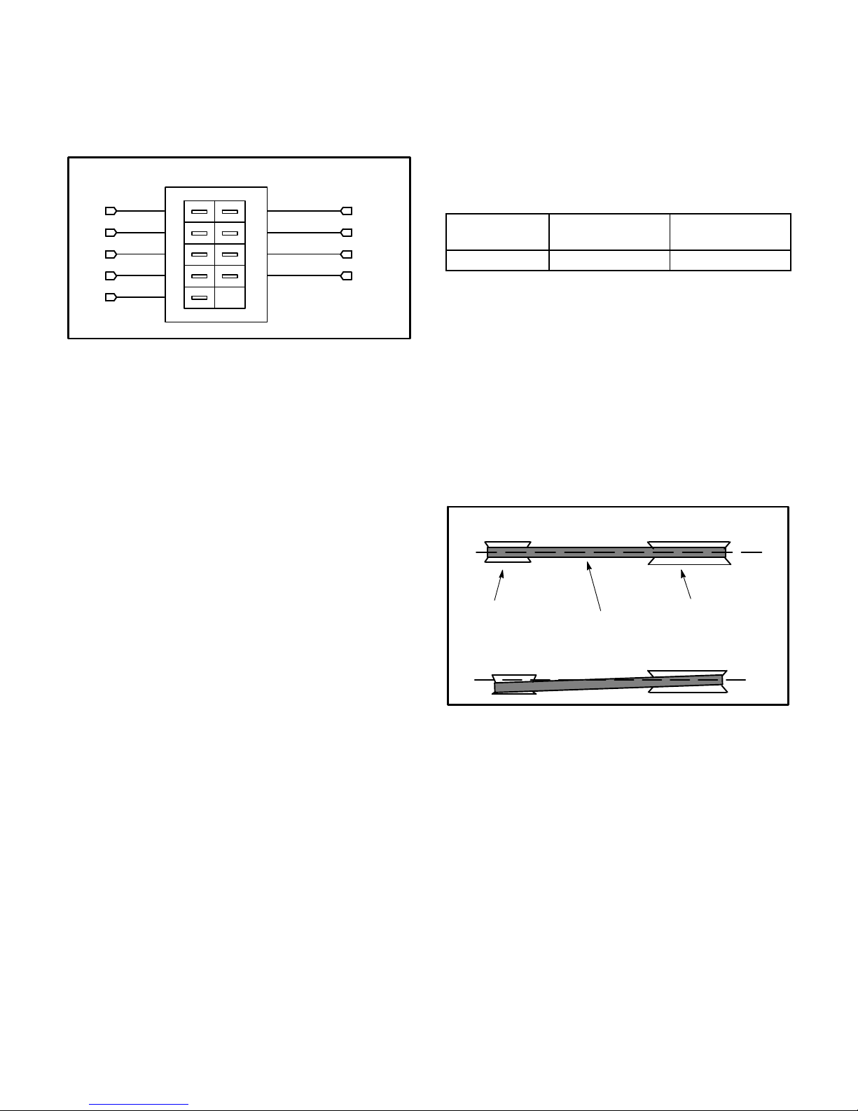
Maximum life and wear can be obtained from belts only
if proper pulley alignment and belt tension are
maintained. Tension new belts after a 24-48 hour
period of operation. This will allow belt to stretch and
seat in the pulley grooves. Make sure blower and motor
pulleys are aligned as shown in figure 17.
1- Loosen four bolts securing motor base to mounting
frame. See figure 18.
PULLEY ALIGNMENT
ALIGNED
MOTOR
PULLEY
BELT
NOT ALIGNED
BLOWER
PULLEY
FIGURE 17
Page 11
Page 12

BLOWER ASSEMBLY
TO INCREASE CFM
LOOSEN ALLEN SCREW &
TURN PULLEY CLOCKWISE
SIDE VIEW
MOTOR
TO INCREASE BELT TENSION
1-Loosen four bolts securing motor base to mounting
frame.
2-Slide the motor downward to tighten the belt.
3-Tighten four bolts on motor base.
TO DECREASE CFM
TURN PULLEY
COUNTERCLOCKWISE
ALLEN
SCREW
PULLEY
2- To increase belt tension -
Slide blower motor downward to tighten the belt. This
increases the distance between the blower motor and
the blower housing.
To loosen belt tension -
Slide blower motor upward to loosen the belt. This
decreases the distance between the blower motor
and the blower housing.
LOOSEN ALLEN
SCREW TO
ADJUST CFM
LOOSEN FOUR BOLTS AND
SLIDE BLOWER MOTOR
DOWNWARD TO TIGHTEN BELT
FIGURE 18
(35-48kPa). For a new 5hp belt, the deflection force
should be 7-10lbs. (48-69kPa).
A force below these values indicates an
undertensioned belt. A force above these values
indicates an overtensioned belt.
MEASURE BELT TENSION
3- Tighten four bolts securing motor base to the
mounting frame.
E-Check Belt Tension
Overtensioning belts shortens belt and bearing life.
Check belt tension as follows:
1- Measure span length X. See figure 19.
2- Apply perpendicular force to center of span (X) with
enough pressure to deflect belt 1/64” for every inch
of span length or 1.5mm per 100mm of span length.
Example: Deflection distance of a 40” span would be
40/64” or 5/8”.
Example: Deflection distance of a 400mm span
would be 6mm.
3- Measure belt deflection force. For a new 2 and 3hp
belt, the deflection force should be 5.0-7.0 lbs.
FORCE
DEFLECTION 1/64” PER INCH OF SPAN
OR 1.5mm PER 100mm OF SPAN
FIGURE 19
F-Field-Furnished Blower Drives
For field-furnished blower drives, use pages to
determine BHP and RPM required. Reference pages
17 to 23 to determine the drive number. Reference table
3 for drive component manufacturer's numbers.
Page 12
Page 13

BLOWER DATA - DIRECT DRIVE - HIGH EFFICIENCY 2 TON
BLOWER TABLE INCLUDES RESISTANCE FOR BASE UNIT ONLY WITH DRY INDOOR COIL AND AIR FILTERS IN PLACE.
FOR ALL UNITS ADD:
1 - Any factory installed options air resistance (economizer, wet coil, etc.) See page 23.
2 - Any eld installed accessories air resistance (electric heat, duct resistance, diffuser, etc.) See page 23.
External Static
Pressure in. w.g.
DOWNFLOW KDB024H4E
0.0 635 825 918 1121 1336
0.1 547 763 861 1071 1290
0.2 433 699 806 1031 1253
0.3 371 636 749 986 1212
0.4 280 559 677 927 1166
0.5 217 481 605 868 1120
0.6 - - - - - - 548 819 1071
0.7 - - - - - - 491 773 1029
0.8 - - - - - - 442 714 983
0.9 - - - - - - 393 653 929
1.0 - - - - - - - - - 604 879
HORIZONTAL KDB024H4E
0.0 602 815 908 1096 1302
0.1 509 750 852 1057 1263
0.2 413 689 793 1007 1227
0.3 340 625 736 964 1189
0.4 266 561 679 918 1142
0.5 220 501 620 864 1100
0.6 - - - - - - 560 809 1061
0.7
0.8 - - - - - - 444 706 964
0.9 - - - - - - 390 661 913
1.0 - - - - - - 352 612 872
Tap 1 Tap 2 Tap 3 Tap 4 Tap 5
- - - - - - 500 752 1015
Air Volume at Specic Blower Taps (cfm)
Page 13
Page 14

BLOWER DATA - DIRECT DRIVE - HIGH EFFICIENCY 3 TON
BLOWER TABLE INCLUDES RESISTANCE FOR BASE UNIT ONLY WITH DRY INDOOR COIL AND AIR FILTERS IN PLACE.
FOR ALL UNITS ADD:
1 - Any factory installed options air resistance (economizer, wet coil, etc.) See page 23.
2 - Any eld installed accessories air resistance (electric heat, duct resistance, diffuser, etc.) See page 23.
External Static
Pressure in. w.g.
DOWNFLOW KDB036H4E
0.0 893 1035 1375 1600 1840
0.1 838 965 1330 1574 1780
0.2 768 895 1277 1543 1748
0.3 705 800 1253 1505 1712
0.4 645 750 1200 1473 1677
0.5 575 690 1150 1435 1638
0.6 - - - - - - 1095 1390 1608
0.7 - - - - - - 1052 1345 1577
0.8 - - - - - - 1004 1302 1528
0.9 - - - - - - 950 1260 1491
1.0 - - - - - - 900 1218 1455
HORIZONTAL KDB036H4E
0.0 900 1045 1379 1599 1810
0.1 828 970 1305 1549 1749
0.2 777 900 1264 1504 1718
0.3 702 800 1216 1479 1677
0.4 635 750 1173 1434 1649
0.5 553 685 1131 1399 1622
0.6 - - - - - - 1078 1359 1577
0.7
0.8 - - - - - - 986 1280 1509
0.9 - - - - - - 933 1236 1471
1.0 - - - - - - 885 1196 1438
Tap 1 Tap 2 Tap 3 Tap 4 Tap 5
- - - - - - 1038 1315 1544
Air Volume at Specic Blower Taps (cfm)
Page 14
Page 15

BLOWER DATA - DIRECT DRIVE - HIGH EFFICIENCY 4 TON
BLOWER TABLE INCLUDES RESISTANCE FOR BASE UNIT ONLY WITH DRY INDOOR COIL AND AIR FILTERS IN PLACE.
FOR ALL UNITS ADD:
1 - Any factory installed options air resistance (economizer, wet coil, etc.) See page 23.
2 - Any eld installed accessories air resistance (electric heat, duct resistance, diffuser, etc.) See page 23.
External Static
Pressure in. w.g.
DOWNFLOW KDB048H4E
0.0 1225 1310 1561 2015 2168
0.1 1167 1254 1514 1995 2143
0.2 1112 1203 1473 1977 2126
0.3 1052 1145 1424 1942 2097
0.4 1000 1098 1387 1917 2078
0.5 939 1040 1343 1888 2049
0.6 894 996 1300 1854 2020
0.7 840 941 1250 1819 1991
0.8 780 883 1201 1787 1952
0.9 734 839 1159 1749 1914
1.0 681 784 1115 1704 1856
HORIZONTAL KDB048H4E
0.0 1185 1265 1504 1983 2120
0.1 1130 1213 1467 1957 2098
0.2 1085 1171 1432 1932 2077
0.3 1035 1125 1395 1906 2054
0.4 978 1069 1347 1870 2023
0.5 929 1023 1304 1841 1992
0.6 880 977 1267 1811 1962
0.7
0.8 764 863 1175 1740 1900
0.9 718 820 1133 1710 1869
1.0 549 712 1096 1652 1772
Tap 1 Tap 2 Tap 3 Tap 4 Tap 5
822 920 1224 1776 1931
Air Volume at Specic Blower Taps (cfm)
Page 15
Page 16

BLOWER DATA - DIRECT DRIVE - HIGH EFFICIENCY 5 TON
BLOWER TABLE INCLUDES RESISTANCE FOR BASE UNIT ONLY WITH DRY INDOOR COIL AND AIR FILTERS IN PLACE.
FOR ALL UNITS ADD:
1 - Any factory installed options air resistance (economizer, wet coil, etc.) See page 23.
2 - Any eld installed accessories air resistance (electric heat, duct resistance, diffuser, etc.) See page 23.
External Static
Pressure in. w.g.
DOWNFLOW KDB060H4E
0.0 1351 1405 1801 1982 2339
0.1 1303 1359 1769 1956 2310
0.2 1254 1314 1736 1928 2281
0.3 1206 1268 1703 1900 2253
0.4 1158 1222 1669 1870 2224
0.5 1109 1177 1634 1838 2195
0.6 1061 1131 1598 1806 2166
0.7 1012 1085 1561 1772 2137
0.8 964 1040 1524 1736 2108
0.9 915 994 1486 1700 2080
1.0 867 949 1446 1662 2051
HORIZONTAL KDB60H4E
0.0 1329 1353 1728 1886 2206
0.1 1284 1320 1708 1872 2189
0.2 1239 1285 1685 1859 2174
0.3 1193 1258 1661 1832 2157
0.4 1147 1218 1636 1814 2135
0.5 1100 1178 1608 1796 2118
0.6 1052 1125 1579 1770 2102
0.7
0.8 955 1044 1516 1716 2058
0.9 906 991 1481 1689 2036
1.0 856 938 1445 1654 2020
Tap 1 Tap 2 Tap 3 Tap 4 Tap 5
1004 1085 1548 1743 2080
Air Volume at Specic Blower Taps (cfm)
Page 16
Page 17

BLOWER DATA - BELT DRIVE 3 TON
BLOWER TABLE INCLUDES RESISTANCE FOR BASE UNIT ONLY WITH DRY INDOOR COIL AND AIR FILTERS IN PLACE.
FOR ALL UNITS ADD:
1 - Any factory installed options air resistance (larger gas heat section, economizer, wet coil, etc.).
2 - Any eld installed accessories air resistance (duct resistance, diffuser, etc.).
See page 23 for blower motors and drives and wet coil and options/accessory air resistance data.
DOWNFLOW KDB036H4T
Air
Volume
cfm
700 447 0.09 517 0.12 589 0.15 663 0.17 739 0.19 815 0.20 883 0.23 938 0.25
800 465 0.10 534 0.14 605 0.17 678 0.19 753 0.21 825 0.23 890 0.25 946 0.27
900 486 0.12 554 0.16 623 0.20 695 0.22 767 0.23 836 0.25 897 0.28 953 0.30
1000 508 0.15 576 0.19 643 0.22 713 0.24 783 0.26 848 0.28 907 0.30 961 0.33
1100 533 0.18 599 0.22 665 0.25 733 0.27 800 0.28 863 0.31 919 0.34 971 0.36
1200 560 0.21 625 0.25 689
1300 591 0.24 654 0.28 716 0.31 779 0.33 841 0.35 897 0.38 948 0.41 996 0.44
1400 631 0.26 690 0.30 748 0.34 807 0.36 864 0.39 916 0.42 964 0.46 1011 0.49
1500 676 0.28 729 0.33 782 0.36 835 0.40 887 0.43 935 0.47 981 0.50 1028 0.54
Air
Volume
cfm
700 988 0.27 1039 0.29 1088 0.31 - - - - - - - - - - - - - - - - - - - - - - - - - - - - - -
800 996 0.30 1047 0.32 1098 0.34 1144 0.36 1185 0.39 1224 0.42 - - - - - - - - - - - -
900 1004 0.33 1055 0.35 1106 0.37 1152 0.40
1000 1011 0.36 1062 0.38 1111 0.41 1157 0.43 1199 0.47 1238 0.50 1276 0.53 1311 0.56
1100 1020 0.39 1070 0.41 1118 0.44 1163 0.47 1206 0.51 1245 0.54 1282 0.58 1318 0.61
1200 1031 0.43 1079 0.45 1127 0.48 1171 0.52 1213 0.55 1252 0.59 1289 0.62 1324 0.66
1300 1044 0.47 1091 0.49 1137 0.53 1181 0.56 1221 0.60 1259 0.64 1296 0.68 1330 0.71
1400 1058 0.51 1105 0.54 1150 0.57 1191 0.61 1231 0.65 1268 0.69 1303 0.73 1337 0.77
1500 1074 0.56 1120 0.59 1163 0.63 1203 0.67 1241 0.71 1277 0.75 1312 0.79 1345 0.82
0.10 0.20 0.30 0.40 0.50 0.60 0.70 0.80
RPM BHP RPM BHP RPM BHP RPM BHP RPM BHP RPM BHP RPM BHP RPM BHP
0.28 755 0.30 820 0.32 879 0.34 932 0.37 983 0.40
0.90 1.00 1.10 1.20 1.30 1.40 1.50 1.60
RPM BHP RPM BHP RPM BHP RPM BHP RPM BHP RPM BHP RPM BHP RPM BHP
External Static - in. w.g.
External Static - in. w.g.
1193 0.43 1232 0.46 1269 0.49 1305 0.52
Page 17
Page 18

BLOWER DATA - BELT DRIVE 3 TON
BLOWER TABLE INCLUDES RESISTANCE FOR BASE UNIT ONLY WITH DRY INDOOR COIL AND AIR FILTERS IN PLACE.
FOR ALL UNITS ADD:
1 - Any factory installed options air resistance (larger gas heat section, economizer, wet coil, etc.).
2 - Any eld installed accessories air resistance (duct resistance, diffuser, etc.).
See page 23 for blower motors and drives and wet coil and options/accessory air resistance data.
HORIZONTAL KDB036H4T
Air
Volume
cfm
700 445 0.08 516 0.11 591 0.13 670 0.15 753 0.16 820 0.19 870 0.22 918 0.24
800 463 0.09 534 0.12 608 0.14 685 0.16 766 0.18 830 0.21 878 0.24 926 0.27
900 485 0.11 554 0.14 627 0.16 703 0.18 780 0.21 841 0.23 888 0.27 935 0.30
1000 509 0.13 578 0.16 649 0.19 722 0.21 796 0.23 854 0.26 900 0.29 947 0.33
1100 537 0.16 605 0.19 674 0.21 744 0.24 813 0.26 868 0.29 913 0.33 959 0.36
1200 567 0.19 633 0.22 700
1300 599 0.22 664 0.25 729 0.28 793 0.30 853 0.33 902 0.37 945 0.41 990 0.44
1400 634 0.26 697 0.29 758 0.31 819 0.34 875 0.38 921 0.42 964 0.46 1008 0.49
1500 669 0.30 730 0.33 789 0.36 846 0.39 897 0.42 941 0.47 983 0.51 1028 0.54
Air
Volume
cfm
700 969 0.27 1021 0.29 1071 0.32 - - - - - - - - - - - - - - - - - - - - - - - - - - - - - -
800 977 0.29 1030 0.32 1082 0.34 1128 0.37 1169 0.40 1205 0.42 - - - - - - - - - - - -
900 986 0.32 1039 0.35 1090 0.37 1137 0.40
1000 997 0.35 1048 0.38 1098 0.41 114 0.44 1184 0.47 1221 0.50 1255 0.53 1287 0.56
1100 1008 0.39 1059 0.41 1107 0.44 1150 0.47 1191 0.51 1228 0.54 1263 0.57 1295 0.60
1200 1022 0.43 1071 0.45 1117 0.48 1160 0.52 1200 0.55 1237 0.59 1271 0.62 1303 0.66
1300 1037 0.47 1058 0.50 1130 0.53 1171 0.57 1210 0.60 1246 0.64 1280 0.68 1312 0.71
1400 1054 0.52 1100 0.54 1144 0.58 1183 0.62 1221 0.66 1256 0.70 1290 0.73 1321 0.77
1500 1073 0.57 1117 0.60 1159 0.64 1197 0.67 1234 0.71 1268 0.75 1301 0.79 1332 0.83
0.10 0.20 0.30 0.40 0.50 0.60 0.70 0.80
RPM BHP RPM BHP RPM BHP RPM BHP RPM BHP RPM BHP RPM BHP RPM BHP
0.24 768 0.27 833 0.30 884 0.33 928 0.37 974 0.40
0.90 1.00 1.10 1.20 1.30 1.40 1.50 1.60
RPM BHP RPM BHP RPM BHP RPM BHP RPM BHP RPM BHP RPM BHP RPM BHP
External Static - in. w.g.
External Static - in. w.g.
1177 0.43 1214 0.46 1248 0.49 1280 0.51
Page 18
Page 19

BLOWER DATA - BELT DRIVE 4 TON
BLOWER TABLE INCLUDES RESISTANCE FOR BASE UNIT ONLY WITH DRY INDOOR COIL AND AIR FILTERS IN PLACE.
FOR ALL UNITS ADD:
1 - Any factory installed options air resistance (larger gas heat section, economizer, wet coil, etc.).
2 - Any eld installed accessories air resistance (duct resistance, diffuser, etc.).
See page 23 for blower motors and drives and page 30 for wet coil and options/accessory air resistance data.
DOWNFLOW KDB048H4T
Air
Volume
cfm
900 466 0.10 525 0.14 586 0.17 646 0.20 729 0.20 821 0.19 899 0.20 953 0.23
1000 484 0.12 543 0.16 603 0.19 664 0.22 745 0.23 834 0.23 908 0.24 959 0.26
1100 505 0.15 563 0.18 622 0.22 682 0.25 762 0.26 847 0.26 917 0.27 966 0.30
1200 527 0.18 584 0.21 643 0.25 702 0.28 779 0.30 860 0.30 927 0.31 973 0.34
1300 550 0.21 607 0.25 664 0.29 722 0.32 797 0.33 875 0.34 937 0.35 981 0.38
1400 574 0.25 630
1500 603 0.28 659 0.32 714 0.36 770 0.39 839 0.41 907 0.42 962 0.44 1002 0.47
1600 651 0.29 703 0.33 754 0.37 806 0.41 867 0.43 927 0.45 976 0.48 1014 0.51
1700 708 0.30 754 0.34 800 0.38 846 0.42 898 0.46 949 0.49 992 0.53 1028 0.57
1800 764 0.31 804 0.36 844 0.40 884 0.45 927 0.49 970 0.54 1008 0.58 1044 0.63
1900 812 0.34 847 0.39 881 0.44 916 0.49 953 0.54 990 0.59 1025 0.64 1061 0.69
2000 857 0.42 889 0.47 920 0.52 952 0.57 986 0.62 1020 0.68 1055 0.73 1091 0.77
Air
Volume
cfm
900 - - - - - - - - - - - - - - - - - - - - - - - - - - - - - - - - - - - - - - - - - - - - - - - -
1000 996 0.31 1034 0.35 - - - - - - - - - - - - - - - - - - - - - - - - - - - - - - - - - - - -
1100 1001 0.34 1040 0.38 1083 0.42 1128 0.46 1176 0.49 - - - - - - - - - - - - - - - - - -
1200 1008 0.38 1047 0.42 1089 0.46 1133 0.49 1180 0.53 1224 0.56 1261 0.60 - - - - - -
1300 1017 0.42 1055 0.46 1097 0.50 1139 0.53 1184 0.57 1228 0.60 1264 0.63 1295 0.67
1400 1026 0.46 1065 0.50 1106 0.54 1147 0.57 1191 0.61 1233 0.64 1269 0.68 1300 0.71
1500 1038 0.51 1076 0.55 1117 0.59 1157 0.62 1199 0.65 1240 0.69 1275 0.72 1305 0.76
1600 1050 0.56 1089 0.60
1700 1065 0.61 1103 0.65 1142 0.69 1181 0.73 1221 0.76 1259 0.80 1292 0.83 1320 0.88
1800 1081 0.67 1118 0.71 1156 0.75 1194 0.79 1234 0.82 1271 0.86 1302 0.90 1330 0.94
1900 1098 0.73 1135 0.77 1172 0.81 1209 0.85 1248 0.88 1284 0.92 1314 0.97 1341 1.01
2000 1128 0.82 1164 0.86 1201 0.89 1239 0.93 1276 0.97 1310 1.01 1336 1.06 1362 1.10
0.10 0.20 0.30 0.40 0.50 0.60 0.70 0.80
RPM BHP RPM BHP RPM BHP RPM BHP RPM BHP RPM BHP RPM BHP RPM BHP
0.29 687 0.32 744 0.35 817 0.37 890 0.38 949 0.39 991 0.42
0.90 1.00 1.10 1.20 1.30 1.40 1.50 1.60
RPM BHP RPM BHP RPM BHP
1129 0.64 1168 0.67 1209 0.71 1249 0.74 1282 0.78 1312 0.82
External Static - in. w.g.
External Static - in. w.g.
RPM BHP RPM BHP RPM BHP RPM BHP RPM BHP
Page 19
Page 20

BLOWER DATA - BELT DRIVE 4 TON
BLOWER TABLE INCLUDES RESISTANCE FOR BASE UNIT ONLY WITH DRY INDOOR COIL AND AIR FILTERS IN PLACE.
FOR ALL UNITS ADD:
1 - Any factory installed options air resistance (larger gas heat section, economizer, wet coil, etc.).
2 - Any eld installed accessories air resistance (duct resistance, diffuser, etc.).
See page 23 for blower motors and drives and wet coil and options/accessory air resistance data.
HORIZONTAL KDB048H4T
Air
Volume
cfm
900 464 0.10 514 0.13 576 0.15 644 0.17 728 0.18 817 0.19 893 0.21 951 0.24
1000 482 0.12 533 0.15 595 0.17 662 0.19 744 0.21 829 0.22 902 0.24 957 0.27
1100 504 0.14 556 0.17 617 0.20 683 0.22 762 0.24 843 0.25 912 0.28 965 0.31
1200 528 0.17 581 0.20 641 0.23 706 0.25 782 0.27 859 0.29 924 0.31 974 0.34
1300 556 0.21 609 0.24 669 0.26 731 0.29 804 0.31 877 0.33 938 0.35 985 0.38
1400 592 0.24 645 0.27 702
1500 641 0.26 692 0.29 746 0.33 801 0.36 862 0.38 921 0.41 970 0.44 1011 0.48
1600 696 0.28 743 0.32 792 0.35 842 0.39 894 0.42 945 0.45 988 0.49 1027 0.53
1700 750 0.31 792 0.35 836 0.39 880 0.43 924 0.47 968 0.51 1007 0.55 1043 0.59
1800 799 0.35 837 0.39 875 0.43 913 0.48 952 0.52 990 0.56 1026 0.61 1061 0.65
1900 840 0.40 873 0.45 907 0.49 941 0.54 976 0.58 1011 0.63 1045 0.67 1080 0.72
2000 883 0.48 913 0.53 944 0.57 976 0.62 1009 0.67 1043 0.71 1078 0.76 1112 0.8
Air
Volume
cfm
900 995 0.28 1034 0.31 1077 0.35 1121 0.38 - - - - - - - - - - - - - - - - - - - - - - - -
1000 999 0.31 1038 0.34 1081 0.38 1124 0.41 1168 0.44 1211 0.47 - - - - - - - - - - - -
1100 1006 0.34 1044 0.38 1086 0.41 1129 0.44 1171 0.47 1213 0.50 1253 0.53 1293 0.56
1200 1014 0.38 1052 0.42 1093 0.45 1135 0.48 1176 0.51 1217 0.54 1257 0.58 1296 0.61
1300 1023 0.42 1061 0.46 1102 0.50 1143 0.53 1184 0.56 1224 0.59 1263 0.62 1302 0.66
1400 1035 0.47 1073 0.51 1112 0.54 1153 0.57 1193 0.61 1232 0.64 1271 0.67 1309 0.71
1500 1048 0.52 1086 0.56 1125 0.59 1164 0.63 1204 0.66 1243 0.69 1280 0.73 1317 0.77
1600 1063 0.57 1100 0.61 1139 0.65
1700 1079 0.63 1116 0.67 1154 0.71 1192 0.74 1230 0.78 1267 0.81 1302 0.85 1337 0.89
1800 1097 0.69 1133 0.73 1171 0.77 1209 0.80 1246 0.84 1281 0.88 1315 0.92 1349 0.96
1900 1116 0.76 1152 0.80 1189 0.84 1226 0.87 1262 0.91 1296 0.95 1329 0.99 1361 1.03
2000 1148 0.84 1183 0.88 1220 0.92 1257 0.96 1291 1.00 1323 1.04 1354 1.08 1385 1.12
0.10 0.20 0.30 0.40 0.50 0.60 0.70 0.80
RPM BHP RPM BHP RPM BHP RPM BHP RPM BHP RPM BHP RPM BHP RPM BHP
0.30 763 0.32 830 0.35 898 0.37 953 0.39 997 0.43
0.90 1.00 1.10 1.20 1.30 1.40 1.50 1.60
RPM BHP RPM BHP RPM BHP RPM BHP
External Static - in. w.g.
External Static - in. w.g.
RPM BHP RPM BHP RPM BHP RPM BHP
1178 0.68 1216 0.71 1254 0.75 1291 0.79 1326 0.83
Page 20
Page 21

BLOWER DATA - BELT DRIVE 5 TON
BLOWER TABLE INCLUDES RESISTANCE FOR BASE UNIT ONLY WITH DRY INDOOR COIL AND AIR FILTERS IN PLACE.
FOR ALL UNITS ADD:
1 - Any factory installed options air resistance (larger gas heat section, economizer, wet coil, etc.).
2 - Any eld installed accessories air resistance (duct resistance, diffuser, etc.).
See page 23 for blower motors and drives and wet coil and options/accessory air resistance data.
DOWNFLOW KDB060H4T
Air
Volume
cfm
1100 512 0.15 571 0.19 630 0.23 690 0.26 770 0.26 854 0.26 922 0.27 970 0.30
1200 535 0.18 593 0.22 651 0.26 710 0.30 788 0.30 868 0.30 933 0.31 978 0.34
1300 559 0.22 616 0.26 674 0.29 732 0.34 807 0.34 883 0.34 944 0.35 987 0.38
1400 584 0.26 641 0.29 698 0.33 755 0.37 827 0.37 899 0.38 956 0.40 997 0.43
1500 615 0.29 671 0.33 726 0.36 782 0.41 850 0.41 917 0.42 970 0.44 1009 0.47
1600 665 0.30 716 0.34 768
1700 723 0.31 768 0.35 814 0.39 860 0.47 910 0.47 959 0.50 1001 0.54 1037 0.58
1800 779 0.32 818 0.37 857 0.41 897 0.50 939 0.50 980 0.55 1018 0.59 1054 0.64
1900 826 0.36 859 0.41 894 0.45 928 0.56 964 0.56 1000 0.61 1036 0.66 1072 0.70
2000 857 0.42 889 0.47 920 0.52 952 0.62 986 0.62 1020 0.68 1055 0.73 1091 0.77
2100 878 0.49 909 0.54 940 0.59 973 0.70 1006 0.70 1041 0.75 1076 0.80 1112 0.85
2200 897 0.55 929 0.61 961 0.66 994 0.78 1028 0.78 1063 0.83 1099 0.89 1134 0.93
2300 918 0.62 950 0.68 983 0.74 1017 0.86 1052 0.86 1087 0.92 1122 0.97 1157 1.02
2400 941 0.70 974
Air
Volume
cfm
1100 1006 0.35 1045 0.39 1089 0.43 1134 0.46 - - - - - - - - - - - - - - - - - - - - - - - -
1200 1013 0.38 1053 0.42 1095 0.46 1139 0.50 1186 0.53 1230 0.57 1266 0.60 - - - - - -
1300 1022 0.42 1062 0.46 1104 0.50 1146 0.54 1192 0.57 1234 0.60 1269 0.64 1301 0.68
1400 1033 0.47 1072 0.51 1114 0.55 1155 0.58 1199 0.61 1240 0.65 1275 0.68 1305 0.72
1500 1045 0.52 1085 0.56 1125 0.60 1165 0.63 1208 0.66 1248 0.69 1281 0.73 1311 0.77
1600 1059 0.57 1098 0.61 1138 0.65
1700 1074 0.62 1113 0.66 1152 0.70 1190 0.74 1231 0.77 1268 0.80 1299 0.84 1328 0.89
1800 1091 0.68 1129 0.72 1167 0.76 1205 0.80 1244 0.83 1280 0.87 1310 0.91 1338 0.95
1900 1109 0.75 1146 0.79 1183 0.82 1221 0.86 1260 0.90 1294 0.94 1323 0.98 1349 1.02
2000 1128 0.82 1164 0.86 1201 0.89 1239 0.93 1276 0.97 1310 1.01 1336 1.06 1362 1.10
2100 1148 0.89 1185 0.93 1221 0.97 1258 1.01 1294 1.05 1325 1.09 1351 1.14 1376 1.19
2200 1170 0.97 1206 1.01 1242 1.05 1277 1.09 1311 1.14 1341 1.18 1365 1.23 1390 1.28
2300 1193 1.06 1228 1.09 1262 1.14 1295 1.19 1327 1.24 1355 1.29 1380 1.33 1406 1.37
2400 1216 1.15 1250 1.19
0.10 0.20 0.30 0.40 0.50 0.60 0.70 0.80
RPM BHP RPM BHP RPM BHP RPM BHP RPM BHP RPM BHP RPM BHP RPM BHP
0.38 819 0.44 879 0.44 937 0.46 985 0.49 1022 0.52
0.77 1008 0.83 1042 0.96 1077 0.96 1111 1.01 1146 1.06 1181 1.11
0.90 1.00 1.10 1.20 1.30 1.40 1.50 1.60
RPM BHP RPM BHP RPM BHP RPM BHP RPM BHP RPM BHP RPM BHP RPM BHP
1282 1.24 1313 1.30 1343 1.36 1371 1.40 1396 1.44 1423 1.48
External Static - in. w.g.
External Static - in. w.g.
1177 0.68 1218 0.71 1257 0.75 1290 0.79 1319 0.83
Page 21
Page 22

BLOWER DATA - BELT DRIVE 5 TON
BLOWER TABLE INCLUDES RESISTANCE FOR BASE UNIT ONLY WITH DRY INDOOR COIL AND AIR FILTERS IN PLACE.
FOR ALL UNITS ADD:
1 - Any factory installed options air resistance (larger gas heat section, economizer, wet coil, etc.).
2 - Any eld installed accessories air resistance (duct resistance, diffuser, etc.).
See page 23 for blower motors and drives and wet coil and options/accessory air resistance data.
HORIZONTAL KDB060H4T
Air
Volume
cfm
1100 509 0.15 562 0.18 624 0.20 691 0.22 771 0.24 852 0.25 919 0.28 970 0.31
1200 535 0.18 589 0.21 650 0.23 715 0.25 792 0.27 869 0.29 932 0.32 980 0.35
1300 564 0.21 618 0.24 678 0.27 741 0.29 815 0.31 887 0.33 946 0.36 991 0.39
1400 604 0.24 657 0.27 715 0.30 775 0.33 842 0.35 908 0.37 962 0.40 1004 0.43
1500 656 0.26 706 0.30 760 0.33 814 0.36 874 0.39 931 0.41 979 0.45 1019 0.48
1600 712 0.29 758 0.32 807
1700 766 0.32 808 0.36 850 0.40 892 0.44 936 0.47 978 0.51 1016 0.56 1052 0.60
1800 814 0.36 851 0.40 888 0.44 925 0.49 963 0.53 1000 0.57 1035 0.62 1071 0.66
1900 853 0.41 886 0.46 919 0.50 952 0.55 986 0.60 1021 0.64 1056 0.69 1091 0.73
2000 883 0.48 913 0.53 944 0.57 976 0.62 1009 0.67 1043 0.71 1078 0.76 1112 0.80
2100 906 0.56 936 0.60 967 0.65 999 0.70 1033 0.75 1067 0.79 1101 0.84 1135 0.88
2200 930 0.64 960 0.68 991 0.73 1024 0.78 1058 0.83 1092 0.88 1126 0.92 1160 0.96
2300 954 0.72 985 0.77 1017 0.82 1051 0.87 1085 0.92 1119 0.96 1152 1.00 1186 1.04
2400 981 0.81 1013
Air
Volume
cfm
1100 1010 35.00 1049 0.38 1091 0.42 1134 0.45 1176 0.78 1218 0.51 1258 0.54 1297 0.57
1200 1019 0.38 1058 0.42 1099 0.46 1141 0.49 1182 0.52 1223 0.55 1263 0.58 1302 0.61
1300 1030 0.43 1068 0.47 1108 0.50 1149 0.53 1190 0.56 1230 0.59 1270 0.63 1308 0.66
1400 1042 0.47 1080 0.51 1120 0.55 1160 0.58 1200 0.61 1240 0.65 1278 0.68 1315 0.72
1500 1056 0.53 1094 0.57 1133 0.60 1172 0.63 1212 0.67 250 0.70 1288 0.74 1324 0.77
1600 1071 0.58 1109 0.62 1147 0.66
1700 1088 0.64 1126 0.68 1164 0.72 1202 0.75 1240 0.78 1276 0.82 1311 0.86 1345 0.90
1800 1107 0.70 1143 0.74 1181 0.78 1219 0.81 1256 0.85 1290 0.89 1324 0.93 1357 0.97
1900 1126 0.77 1163 0.81 1200 0.85 1237 0.88 1273 0.92 1306 0.96 1339 1.00 1371 1.04
2000 1148 0.84 1183 0.88 1220 0.92 1257 0.96 1291 1.00 1323 1.04 1354 1.08 1385 1.12
2100 1170 0.92 1206 0.96 1242 1.00 1277 1.04 1310 1.08 1340 1.13 1370 1.17 1401 1.21
2200 1195 1.00 1230 1.04 1265 1.08 1299 1.13 1330 1.18 1359 1.23 1388 1.27 1418 1.31
2300 1220 1.08 1254 1.13 1288 1.17 1320 1.23 1350 1.28 1378 1.34 1406 1.38 1435 1.42
2400 1245 1.18 1278 1.22
0.10 0.20 0.30 0.40 0.50 0.60 0.70 0.80
RPM BHP RPM BHP RPM BHP RPM BHP RPM BHP RPM BHP RPM BHP RPM BHP
0.36 855 0.39 906 0.43 955 0.46 997 0.50 1035 0.54
0.86 1046 0.91 1079 0.96 1113 1.00 1180 1.05 1180 1.09 1213 1.13
0.90 1.00 1.10 1.20 1.30 1.40 1.50 1.60
RPM BHP RPM BHP RPM BHP RPM BHP RPM BHP RPM BHP RPM BHP RPM BHP
1311 1.28 1341 1.33 1370 1.40 1397 1.45 1425 1.50 1454 1.54
External Static - in. w.g.
External Static - in. w.g.
1186 0.69 1225 0.72 1263 0.76 1299 0.80 1334 0.83
Page 22
Page 23

BLOWER DATA
BELT DRIVE KIT SPECIFICATIONS
Model
No.
036 0.75 0.86 2 low 449-673
048 0.75 0.86 2 - - - low 497-673
060 1 1.15 2 low 555-833
NOTE - Using total air volume and system static pressure requirements determine from blower performance tables rpm and motor hp required. Maximum usable hp of
motors furnished are shown. In Canada, nominal motor hp is also maximum usable motor hp. If motors of comparable hp are used, be sure to keep within the service
factor limitations outlined on the motor nameplate.
OPTIONS / ACCESSORIES AIR RESISTANCE - in. w.g.
Air Volume
cfm
800 0.01 0.01 0.02 0.02 0.04 0.04 0.05
1000 0.02 0.01 0.02 0.02 0.04 0.04 0.07
1200 0.02 0.01 0.02 0.02 0.04 0.04 0.07
1400 0.03 0.02 0.02 0.03 0.04 0.04 0.07
1600 0.04 0.03 0.03 0.04 0.04 0.04 0.07
1800 0.05 0.04 0.03 0.05 0.05 0.05 0.07
2000 0.06 0.05 0.04 0.06 0.05 0.05 0.08
2200 0.08 0.06 0.04 0.07 0.05 0.05 0.08
2400 0.09 0.07 0.05 0.08 0.05 0.05 0.08
2600 0.10 0.08 0.05 0.09 0.06 0.05 0.08
2800 0.11 0.09 0.06 0.10 0.06 0.05 0.08
3000 0.13 0.10 0.07 0.11 0.06 0.05 0.08
Motor HP No. of
Nominal Maximum A01 A02 A03 A05 A06 A07
Speeds
Drive Kits and RPM Range
- - - - - - - - - - - - - - -
high 673-1010
1 1.15 2 - - - - - - - - - low 598-897
- - - - - -
high 897-1346
- - - - - - - - - - - -
high 745-1117
2 2.3 2 - - - - - - - - - - - - low 714-953
- - -
high 1071-1429
high 833-1250
2 2.3 2 low 808-1032
high 1212-1548
Wet Indoor Coil Gas Heat
024 036, 048 060 Medium Input High Input MERV 8 MERV 13
Economizer
Filters
CEILING DIFFUSERS AIR RESISTANCE (in. w.g.)
Air Volume
cfm
2 Ends
Open
RTD9-65S Step–Down Diffuser FD9-65S Flush
1 Side &
All Ends & Sides Open
2 Ends Open
800 0.15 0.13 0.11 0.11
1000 0.19 0.16 0.14 0.14
1200 0.25 0.20 0.17 0.17
1400 0.33 0.26 0.20 0.20
1600 0.43 0.32 0.20 0.24
1800 0.56 0.40 0.30 0.30
2000 0.73 0.50 0.36 0.36
2200 0.95 0.63 0.44 0.44
Page 23
Diffuser
Page 24

MANUFACTURER'S NUMBERS
TABLE 3
DRIVE COMPONENTS
MOTOR PULLEY BLOWER PULLEY BELTS
Drive No.
A01 1VP34 X 3/8 31K6901 AK54 X 1 100244-19 A40 100245-17
A02 1VP34 X 3/8 31K6901 AK49 X 1 100244-18 A39 100245-16
A03 1VP34 X 3/8 31K6901 AK44X 1 100244-16 A39 100245-16
A04 1VP40 X 3/8 79J0301 AK49 X 1 100244-18 A41 100245-18
A05 1VP34 X 3/8 31K6901 AK41 X 1 100244-15 A38 100245-15
A06 1VP44 X 3/8 P-8-1488 AK51 X 1 18L2201 A41 100245-18
A07 1VP50 X 3/8 53J1501 AK54 X 1 100244-19 AX43 73K8201
A08 1VP44 X 3/8 P-8-1488 AK46 X 1 100244-17 A40 100245-17
Browning No. OEM Part No. Browning No. OEM Part No. Browning No. OEM Part No.
Start-Up
IMPORTANT
If unit is equipped with a crankcase heater. Make
sure heater is energized 24 hours before unit startup to prevent compressor damage as a result of
slugging.
A-Start-Up
Heating
1- Set thermostat or temperature control device to
initiate a first-stage heating demand.
2- A first-stage heating demand (W1) will energize
compressors 1 and the outdoor fan.
Note - L1 reversing valve is de-energized in the
heating mode.
Cooling
1- Initiate first and second stage cooling demands
according to instructions provided with thermostat.
See table 4 for operation.
2- Units contain one refrigerant circuit or stage.
Note - Units are equipped with two-stage compressors.
3- Unit is charged with R-410A refrigerant. See unit
rating plate for correct amount of charge.
4- Refer to Refrigerant Charge and Check section for
proper method to check refrigerant charge.
TABLE 4
COOLING OPERATION
T'Stat
Demand
No Economizer or Outdoor Air Unsuitable
Y1 Compressor Low Speed* OD Fan Low Sp.
Y2 Compressor High Speed** OD Fan High Sp.
Unit Equipped With An Economizer
Y1 Economizer na
Y2
Economizer + Compressor
Low Speed*
Energized
OD Fan Low Sp.
*67% of full capacity
**100% of full capacity
Note - The reversing valve is energized at the same time
as the compressor.
Page 24
Page 25

B-Three Phase Scroll Compressor Voltage Phasing
Three phase scroll compressors must be phased
sequentially to ensure correct compressor and blower
rotation and operation. Compressor and blower are
wired in phase at the factory. Power wires are
color-coded as follows: line 1-red, line 2-yellow, line
3-blue.
1- Observe suction and discharge pressures and
blower rotation on unit start-up.
2- Suction pressure must drop, discharge pressure
must rise, and blower rotation must match rotation
marking.
If pressure differential is not observed or blower rotation is
not correct:
3- Disconnect all remote electrical power supplies.
4- Reverse any two field-installed wires connected to
the line side of K1 contactor. Do not reverse wires at
blower contactor.
Make sure the connections are tight.
Discharge and suction pressures should operate at
their normal start‐up ranges.
C-Refrigerant Charge and Check
WARNING-Do not exceed nameplate charge under
any condition.
This unit is factory charged and should require no further
adjustment. If the system requires additional refrigerant,
reclaim the charge,
evacuate the system, and add
required nameplate charge.
NOTE - System charging is not recommended below
60F (15C). In temperatures below 60F (15C), the
charge must be weighed into the system.
If weighing facilities are not available, or to check the
charge, use the following procedure:
IMPORTANT - Charge unit in standard cooling mode.
1- Make sure outdoor coil is clean. Attach gauge
manifolds and operate unit at full CFM in cooling mode
with economizer disabled until system stabilizes
(approximately five minutes). Make sure all outdoor air
dampers are closed.
2- Compare the normal operating pressures (see table
5 through 8) to the pressures obtained from the
gauges. Check unit components if there are
significant differences.
3- Measure the outdoor ambient temperature and the
suction pressure. Refer to the appropriate circuit
charging curve to determine a target liquid
temperature.
Note - Pressures are listed for sea level applications.
4- Use the same thermometer to accurately measure the
liquid temperature (in the outdoor section).
If measured liquid temperature is higher than
the target liquid temperature, add refrigerant to
the system.
If measured liquid temperature is lower than
the target liquid temperature, recover some
refrigerant from the system.
5- Add or remove charge in increments. Allow the
system to stabilize each time refrigerant is added or
removed.
6- Continue the process until measured liquid
temperature agrees with the target liquid
temperature. Do not go below the target liquid
temperature when adjusting charge. Note that
suction pressure can change as charge is adjusted.
7- Example KDB024: At 95°F outdoor ambient and a
measured suction pressure of 130psig, the target
liquid temperature is 102°F. For a measured liquid
temperature of 112°F, add charge in increments
until measured liquid temperature agrees with the
target liquid temperature.
Page 25
Page 26

TABLE 5
KDB024H Normal Operating Pressures
Outdoor Coil Entering Air Temperature
65 °F 75 °F 85 °F 95 °F 105 °F 115 °F
Suct
(psig)
113 217 114 254 11 7 295 119 342 121 395 124 455
120 222 125 259 123 304 128 349 130 401 133 459
141 226 143 262 142 303 145 353 148 404 154 465
154 233 162 270 167 312 170 358 171 410 175 466
Disc
(psig)
Suct
(psig)
Disc
(psig)
Suct
(psig)
Disc
(psig)
Suct
(psig)
Disc
(psig)
Suct
(psig)
Disc
(psig)
Suct
(psig)
Disc
(psig)
TABLE 6
KDB036H Normal Operating Pressures
Outdoor Coil Entering Air Temperature
65 °F 75 °F 85 °F 95 °F 105 °F 115 °F
Suct
(psig)
113 230 115 268 11 7 310 119 358 121 412 121 471
121 233 123 273 125 314 128 364 130 417 130 476
142 240 142 278 144 321 146 370 149 425 151 483
157 247 163 286 165 330 168 378 170 431 173 491
Disc
(psig)
Suct
(psig)
Disc
(psig)
Suct
(psig)
Disc
(psig)
Suct
(psig)
Disc
(psig)
Suct
(psig)
Disc
(psig)
Suct
(psig)
Disc
(psig)
TABLE 7
KDB048H Normal Operating Pressures
Outdoor Coil Entering Air Temperature
65 °F 75 °F 85 °F 95 °F 105 °F 115 °F
Suct
(psig)
107 234 109 272 11 0 314 112 363 116 409 11 7 462
115 242 117 279 11 9 321 121 366 123 415 123 470
129 247 134 284 137 328 140 375 143 425 144 480
134 251 145 292 154 335 159 382 162 432 164 489
Disc
(psig)
Suct
(psig)
Disc
(psig)
Suct
(psig)
Disc
(psig)
Suct
(psig)
Disc
(psig)
Suct
(psig)
Disc
(psig)
Suct
(psig)
Disc
(psig)
TABLE 8
KDB060H Normal Operating Pressures
Outdoor Coil Entering Air Temperature
65 °F 75 °F 85 °F 95 °F 105 °F 115 °F
Suct
(psig)
105 236 106 274 109 317 11 2 365 115 419 11 9 474
115 243 119 280 11 9 324 122 372 124 422 129 480
135 251 137 289 139 332 142 381 146 432 148 489
152 261 157 300 160 344 163 392 166 443 170 500
Disc
(psig)
Suct
(psig)
Disc
(psig)
Suct
(psig)
Disc
(psig)
Suct
(psig)
Disc
(psig)
Suct
(psig)
Disc
(psig)
Suct
(psig)
Disc
(psig)
Page 26
Page 27

130
120
110
100
90
KDB 024H Charging Curves
Outdoor Temperature (°F)
115°
105°
95°
85°
Liquid Temperature (° F)
80
70
65°
60
110 120 130 140 150 160 170
Suction Pressure (psig)
KDB 036H Charging Curves
Outdoor Temperature (°F)
130
120
110
100
75°
180
115°
105°
95°
90
Liquid Temperature (° F)
80
70
60
110 120 130 140 150 160 170
85°
75°
65°
180
Suction Pressure (psig)
Page 27
Page 28

Liquid Temperature (° F)
130
120
110
100
90
80
KDB 048H Charging Curves
Outdoor Temperature (°F)
115°
105°
95°
85°
75°
65°
Liquid Temperature (° F)
70
130
120
110
100
90
100
110 120 130 140 150 160 170
Suction Pressure (psig)
KDB 060H Charging Curves
Outdoor Temperature (°F)
115°
105°
95°
85°
75°
80
70
100
110 120 130 140 150 160 170
65°
Suction Pressure (psig)
Page 28
Page 29

D - Compressor Controls
See unit wiring diagram to determine which controls are
used in each unit. Optional controls are identified on
wiring diagrams by arrows at junction points.
1- Freezestat (S49)
Switch de-energizes compressor when indoor coil
temperature falls below 29F (-2C) to prevent coil
freeze-up. Switch resets when indoor coil
temperature reaches 58F (15C).
2- High Pressure Switch (S4)
Auto-reset switch is located on the discharge line.
Switch opens at 640 psig and closes at 475 psig.
Switch is wired directly into the defrost control
(CMC1), which provides a 5 strike lockout feature.
3- Defrost Switch (S6)
100269 Series Only
Defrost switch closes to initiate defrost when liquid
line temperature falls to 42° F (5.6°C). Defrost switch
opens when liquid line temperature reaches 70°F
(21°C) to terminate defrost. If the liquid line
temperature does not rise above 70°F (21°C), the
CMC1 will terminate defrost after 14 minutes. The
defrost switch is located on the liquid line between the
outdoor expansion valve and the distributor
a defrost cycle begins and operates for 14 minutes.
The defrost switch can terminate the defrost cycle
before the 14 minutes elapses if liquid line
temperature reaches 70°F (21°C).
Note - The defrost control will not energize a defrost cycle
unless the unit has been operating in heating mode for an
accumulated 90 minutes (default) on 100269 series
boards. The run time interval can be changed by moving
the jumper on the CMC board timing pins. See figure 20.
The defrost interval can be adjusted to 30, 60, or 90
minutes. If the timing selector jumper is not in place, the
control defaults to a 90-minute defrost interval.
DEFROST CONTROL BOARD CMC1
TIMING JUMPER:
100269 SERIES: 90 MINUTES
DIAGNOSTIC
LEDS
4- Ambient and Coil Temperature Sensors (RT13, RT21)
100135 Series Only
Both sensors provide input to the defrost control
which cycles defrost. The ambient sensor is located
on the inside of the corner mullion on the back of the
outdoor coil section. The coil sensor is located on a
return bend on the front of the outdoor coil.
5- Defrost Controls (CMC1)
Gas heat is energized during defrost to maintain
discharge air temperature.
100269 Series Time/Temperature
When the liquid line temperature drops below 42°F
(5.6°C), the defrost switch closes and signals the
defrost control that a defrost cycle is needed. If the
defrost switch is still closed after 90 minutes (default),
100269 SERIES:REMOVED
AT THE FACTORY TO DIS
ABLE COMPRESSOR DELAY
FIGURE 20
Page 29
Page 30

DEFROST CONTROL BOARD CMC1
DEFROST TEMPERATURE
TERMINATION JUMPER:
100135-06: 50
5F(105C)
DIAGNOSTIC
LEDS
Defrost Control Board
The defrost control ensures that the heat pump outdoor
coil does not ice excessively during the heating mode.
The defrost control uses input from a defrost switch on
100269 series defrost control boards. The defrost control
uses input from a coil and an ambient temperature sensor
on 100135 series defrost control boards.
Defrost Test Option
COIL AND AMBI
ENT SENSOR
CONNECTIONS
DELAY PINS
REVERSING
VALV E
PRESSURE
SWITCH CIRCUIT
CONNECTIONS
24V TERMINAL
STRIP
CONNECTIONS
FIGURE 21
5- Defrost Controls (CMC1) - Continued
100135 Series Demand Defrost Control
After 34 minutes of heating mode operation, if the
difference between the ambient temperature
(RT13) and the coil temperature (RT21) is higher
than the maximum difference allowed by the
control, the defrost control will initiate defrost. The
defrost control will also initiate defrost after 6
hours of heating mode operation when coil
temperatures remain below 35°F (2°C). The
defrost cycle ends when the coil temperature is
higher than the termination temperature (50°F
default) or after 14 minutes of operation. If the
defrost is terminated by the 14-minute timer,
another defrost cycle will be initiated after 34
minutes of run time.
Note - The defrost termination temperature can be
adjusted to 50, 70, 90 or 1005F. The jumper termination
pin is factory-set at 505F (105 C). If the temperature
jumper is not installed, the default termination
temperature is 905F (325C). See figure 21.
A TEST option is provided for troubleshooting. The TEST
mode may be started any time the unit is in the heating
mode and the defrost thermostat is closed or jumpered. If
the timing jumper is in the TEST position at power‐up, the
defrost control will ignore the test pins. When the jumper
is placed across the TEST pins for two seconds, the
control will enter the defrost mode. If the jumper is
removed before an additional 5-second period has
elapsed (7 seconds total), the unit will remain in defrost
mode until the defrost pressure switch opens or 14
minutes have passed. If the jumper is not removed until
after the additional 5-second period has elapsed, the
defrost will terminate and the test option will not function
again until the jumper is removed and re-applied.
Diagnostic LEDs
The defrost board uses two LEDs for diagnostics. The
LEDs flash a sequence according to the condition.
TABLE 9
Defrost Control Board Diagnostic LED
Mode
No power to control OFF OFF
Normal operation /
power to control
Anti‐short cycle
lockout
Low pressure switch,
freezestat fault
Low pressure switch,
freezestat lockout
High pressure switch
fault
High pressure switch
lockout
*Ambient sensor fault Simultaneous FAST flash
*Coil sensor fault Alternating FAST flash
Green LED
(DS2)
Simultaneous Slow FLASH
Alternating Slow FLASH
OFF Slow FLASH
OFF ON
Slow FLASH OFF
ON OFF
Red LED (DS1)
*100135-06 board only
Page 30
Page 31

Gas Heat Start-Up
FOR YOUR SAFETY READ BEFORE LIGHTING
WARNING
Electric shock hazard. Can cause injury
or death. Do not use this unit if any part
has been under water. Immediately call
a qualified service technician to inspect
the unit and to replace any part of the
control system and any gas control
which has been under water.
This unit is equipped with an automatic spark ignition
system. There is no pilot. In case of a safety shutdown,
move thermostat switch to OFF and return the thermostat
switch to HEAT to reset ignition control.
A-Placing Unit In Operation
WARNING
Danger of explosion and fire. Can cause
injury or product or property damage.
You must follow these instructions
exactly.
WARNING
Danger of explosion. Can cause injury
or product or property damage. If over
heating occurs or if gas supply fails to
shut off, shut off the manual gas valve
to the appliance before shutting off
electrical supply.
WARNING
Electric shock hazard. Can cause
injury or death. Before attempting to
perform any service or maintenance,
turn the electrical power to unit OFF at
disconnect switch(es). Unit may have
multiple power supplies.
WARNING
SMOKE POTENTIAL
The heat exchanger in this unit could be a source of
smoke on initial firing. Take precautions with re
spect to building occupants and property. Vent ini
tial supply air outside when possible.
Gas Valve Operation for Honeywell VR8215S or White
Rodgers 36J54 (figure 22 and 23)
1- Set outdoor thermostat setpoint above the outdoor
ambient temperature to disable heat pump operation.
2- Set thermostat to lowest setting.
3- Turn off all electrical power to appliance.
4- This appliance is equipped with an ignition device
which automatically lights the burner. Do not try to
light the burner by hand.
5- Open or remove the control section access panel.
6- Move gas valve switch to OFF. See figure 22 or 23.
7- Wait five (5) minutes to clear out any gas. If you then
smell gas, STOP! Immediately call your
gas supplier from a neighbor's phone. Follow the gas
supplier's instructions. If you do not smell gas, go to
the next step.
8- Move gas valve switch to ON. See figure 22 or 23.
9- Close or replace the control section access panel.
10- Turn on all electrical power to appliance.
11- Set thermostat to desired setting.
NOTE - When unit is initially started, steps 1 through 9
may need to be repeated to purge air from gas line.
BEFORE LIGHTING smell all around the appliance area
for gas. Be sure to smell next to the floor because some
gas is heavier than air and will settle on the floor.
Use only your hand to push in or turn the gas control knob
or switch. Never use tools. If the switch will not move, or
the knob will not push in or turn by hand, do not try to
repair it, call a qualified service technician. Force or
attempted repair may result in a fire or explosion.
WARNING
Danger of explosion. Can cause injury or
death. Do not attempt to light manually.
Unit has a direct spark ignition system.
Page 31
HONEYWELL VR8215S GAS VALVE
MANIFOLD
PRESSURE
ADJUSTMENT
SCREW
INLET
PRESSURE
PORT
Single-Stage
Gas valve switch shown in ON position.
FIGURE 22
MANIFOLD
PRESSURE
OUTLET
Page 32

WHITE RODGERS 36J54 GAS VALVE
Two- Stage
MANIFOLD
PRESSURE TAP
INLET
PRESSURE
TAP
Gas valve switch is shown in OFF position.
HIGH FIRE
ADJUSTMENT
LOW FIRE
ADJUSTMENT
FIGURE 23
6- The ignition sequence will start.
7- If the appliance does not light the first time (gas line
not fully purged), it will attempt up to two more
ignitions before locking out.
8- If lockout occurs, repeat steps 1 through 10.
9- If the appliance will not operate, follow the
instructions “Turning Off Gas to Appliance” and call
your service technician or gas supplier.
Turning Off Gas to Unit
1- If using an electromechanical thermostat, set to the
lowest setting.
2- Before performing any service, turn off all electrical
power to the appliance.
3- Open or remove the control section access panel.
4- Move gas valve switch to OFF.
5- Close or replace the control section access panel.
WARNING
12- Spark ignitor energizes and gas valve solenoid opens.
13- Spark ignites gas, ignition sensor proves the flame
and combustion continues.
14- If flame is not detected after first ignition trial, ignition
control will repeat steps 3 and 4 two more times
before locking out the gas valve.
15- For troubleshooting purposes, an ignition attempt
after lock out may be re-established manually. Move
thermostat to “OFF” and return thermostat switch to
“HEAT” position.
B-Ignition Control Diagnostic LED's
TABLE 10
IGNITION CONTROL HEARTBEAT LED STATUS
LED
Flashes
Indicates
Slow Normal operation. No call for heat.
Fast Normal operation. Call for heat.
Steady Off
Internal control fault OR no power to
control OR Gas Valve Relay Fault.
Steady On Control internal failure.
2 Lockout. Failed to detect or sustain flame.
3
4
5
Prove switch open or closed or rollout
switch open.
Limit switch is open and/or limit has
opened three times.
Flame sensed but gas valve solenoid
not energized.
C-Limit Controls
Limit controls are factory-set and are not adjustable. The
primary limit is located to the right of the combustion air
inducer. See figure 28.
Danger of explosion. Can cause injury or
death. Do not attempt to light manually.
Unit has a direct spark ignition system.
Heating Operation and Adjustments
A-Heating Sequence of Operation
1- Set outdoor thermostat setpoint above the outdoor
ambient temperature to disable heat pump operation.
2- On a heating demand the combustion air inducer
starts immediately.
3- Combustion air pressure switch proves inducer
operation. After a 30-second pre-purge, power is
allowed to ignition control. Switch is factory set and
requires no adjustment.
If the primary limit trips three times in the same heating
cycle, heating operation will de-energize. Heating will
automatically restart after one hour if a heating demand is
present. To initiate heating during the one hour timed-off
interval, reset the thermostat.
D-Heating Adjustment
Main burners are factory-set and do not require
adjustment.
The following manifold pressures are listed on the gas valve.
Natural Gas Units - Low Fire - 2.0” w.c.
Natural Gas Units - High Fire - 3.5” w.c.
LP Gas Units - Low Fire - 5.9” w.c.
LP Gas Units - High Fire - 10.5” w.c.
Page 32
Page 33

Service
The unit should be inspected once a year by a qualified
service technician.
CAUTION
Label all wires prior to disconnection when servic
ing controls. Wiring errors can cause improper and
dangerous operation. Verify proper operation after
servicing.
A-Lubrication
All motors are lubricated at the factory. No further
lubrication is required.
B-Filters
Units are equipped with four filters. See table 11. Filters
should be checked monthly and replaced when
necessary with filters of like kind and size. Take note of
air flow direction marking on filter frame when
reinstalling filters. See figure 24.
TABLE 11
UNIT FILTERS
Unit Qty Filter Size - in. (mm)
KDB024, 036 4 16 X 20 X 2 (406 X 508 X 51)
KDB048, 060 4 20 X 20 X 2 (508 X 508 X 51)
NOTE-Filters must be U.L.C. certified or equivalent for
use in Canada.
REMOVE FILTERS
PULL TO
REMOVE
FILTERS
FIGURE 24
E-Indoor Coil
Inspect and clean coil at beginning of each cooling and
heating season. Clean using mild detergent or
commercial coil cleanser. Flush coil and condensate
drain with water taking care not to get insulation, filters
and return air ducts wet.
F-Outdoor Coil
C-Supply Air Blower Wheel
Annually inspect supply air blower wheel for accumulated
dirt or dust. Turn off power before attempting to remove
access panel or to clean blower wheel.
D-Filter Drier
The unit is equipped with a bi-flow filter drier. if
replacement is necessary, order another of like design.
CLEAN FIN/TUBE CONDENSER COIL
TOP VIEW
SUPPLY
AIR
BLOWER
CONDENSER ACCESS PANEL
ENDPLATE IS SECURED TO MULLION
CONDENSER
COILS
Clean condenser coil annually with detergent or
commercial coil cleaner and inspect monthly during the
cooling season.
Condenser coils are made of two formed slabs. Dirt and
debris may become trapped between the slabs. To clean
between slabs, carefully separate coil slabs and wash
them thoroughly. See figure 25. Flush coils with water
following cleaning.
1- Remove unit top panel and condenser section access
panel.
2- Remove screws securing coil end plate to mullion.
3- Remove wire ties connecting coil slabs and separate
slabs 3-4” (76-102mm).
4- Clean coils with detergent or commercial coil cleaner.
5- Rinse thoroughly with water and reassemble
6- Secure coil slabs together using field-provided wire
ties.
.
FIGURE 25
Page 33
Page 34

WARNING
This product contains a chemical known to the
State of California to cause cancer, birth defects, or
other reproductive harm.
G-Burners
Periodically examine burner flames for proper
appearance during the heating season. Before each
heating season examine the burners for any deposits or
blockage which may have occurred.
Clean burners as follows:
1- Turn off both electrical power and gas supply to unit.
IGNITOR
SPARK GAP
SHOULD BE 1/8”
(3mm)
FIGURE 27
WARNING
2- Remove blower access panel.
3- Remove top burner box panel and screws securing
burners to burner support and lift the individual
burners or the entire burner assembly from the
orifices. See figure 26. Clean as necessary.
4- Locate the ignitor under the right burners. Check
ignitor spark gap with appropriately sized twist drills
or feeler gauges. See figure 27.
5- Replace burners and screws securing burner. See
figure 26.
6- Replace access panel.
BURNER BOX ASSEMBLY
FLAME
SENSOR
Danger of explosion. Can cause injury or
death. Do not overtighten main burner
mounting screws. Snug tighten only.
7- Restore electrical power and gas supply. Follow
lighting instructions attached to unit and use
inspection port in access panel to check flame.
H-Combustion Air Inducer
A combustion air proving switch checks combustion air
inducer operation before allowing power to the gas
controller. Gas controller will not operate if inducer is
obstructed.
Under normal operating conditions, the combustion air
inducer wheel should be checked and cleaned prior to the
heating season. However, it should be examined
periodically during the heating season to establish an
ideal cleaning schedule. With power supply
disconnected, the condition of the inducer wheel can be
determined by looking through the vent opening.
Clean combustion air inducer as follows:
1- Shut off power supply and gas to unit.
BURNER
ASSEMBLY
GAS MANIFOLD
IGNITOR
FIGURE 26
GAS VALVE
2- Disconnect pressure switch air tubing from
combustion air inducer port.
3- Remove the mullion on the right side of the heat
section.
4- Remove and retain screws securing combustion
air inducer to flue box. Remove vent connector.
See figure 28.
5- Clean inducer wheel blades with a small brush and
wipe off any dust from housing. Clean accumulated
dust from front of flue box cover.
6- Replace the mullion on the right side of the heat
section.
Page 34
Page 35

HEAT EXCHANGER ASSEMBLY
HEAT
EXCHANGER
TUBE
16- Return combustion air inducer motor and vent
connector to original location and secure with
retained screws. It is recommended that the
combustion air inducer gasket be replaced during
reassembly.
COMBUSTION
AIR INDUCER
BURNER
ROLLOUT
SWITCH
PRIMARY
LIMIT
FIGURE 28
VENT
CONNECTOR
FLUE BOX
COVER
GAS VALVE
17- Clean combustion air inlet louvers on heat access
panel using a small brush.
18- Replace mullion.
J-Flue Passageway and Flue Box
1- Remove combustion air inducer assembly as
described in section J.
2- Remove flue box cover. Clean with a wire brush as
required.
3- Clean tubes with a wire brush.
4- Reassemble the unit. The flue box cover gasket and
combustion air inducer gasket should also be
replaced during reassembly.
Page 35
 Loading...