

Page 1

Litho U.S.A.
©2015
INSTALLATION
INSTRUCTIONS
WARNING
Improper installation, adjustment, alteration, ser
vice or maintenance can cause property damage,
personal injury or loss of life. Installation and ser
vice must be performed by a licensed professional
HVAC installer or equivalent, service agency, or the
gas supplier
Table Of Contents
Dimensions Page 2.................................
Parts Arrangements Page 3.........................
Shipping and Packing List Page 4....................
General Page 4....................................
Requirements Page 4...............................
Unit Support Page 5................................
Duct Connection Page 5............................
Rigging Unit For Lifting Page 6.......................
Horizontal Air Discharge Page 6......................
Condensate Drains Page 6..........................
Gas Piping Page 8.................................
Pressure Test Gas Piping Page 9.....................
High Altitude Derate Page 9.........................
Electrical Connections Page 9.......................
Blower Operation and Adjustments Page 11............
Cooling Start-Up Page 42............................
Gas Heat Start-Up Page 51...........................
Heating Operation and Adjustments Page 52............
Electric Heat Start-Up Page 52........................
Service Page 53....................................
KGB/KCB024
KGB/KCB030
KGA/KCA036
KGB/KCB036
KGA/KCA048
KGB/KCB048
KGA/KCA060
KGB/KCB060
KGA/KCA072
KGB/KCB072
KGB/KCB074
KGA/KCA090
GAS AND COOLING PACKAGED UNITS
507348-04
12/2015
Supersedes 507348-01, -02, -03
2-Ton
2-1/2-Ton
3-Ton
3-Ton
4-Ton
4-Ton
5-Ton
5-Ton
6-Ton
6-Ton
6-Ton
6-Ton
7-1/2 Ton
RETAIN THESE INSTRUCTIONS FOR FUTURE REFERENCE
KG SHOWN
Page 2

KG / KC 024, 030, 036, 048, 060, 072, 074, 090 DIMENSIONS in. - Gas heat section shown
Model
No.
KGA/KCA036, 048, 060
KGB/KCB024, 030, 036, 048
KGA/KCA072, 090
KGB/KCB060, 074
7/8
(22)
2-1/4
(Overall dimensions
same as end view
without economizer)
(57)
A
7/8
(22)
OPENING WITH HORIZONTAL
ECONOMIZER INSTALLED
END VIEW
A
in. mm
18-3/4 476
22-1/2 572
30-7/16
(773)
UNIT RETURN AIR DUCT
2-1/4
(57)
5-5/8
(143)
AA
7 (178)
29
(737)
47 (1192)
BASE
DD CC
43-3/8 (1102) KGA/KCA072, 090
& KGB/KCB060, 074
35-3/8 (899) KGA/KCA036-060
& KGB/KCB024-048
3-1/2 (89)
LIFTING HOLES
(For rigging)
16-1/4
(413)
11
(279)
BOTTOM
RETURN
AIR
OPENING
BOTTOM
SUPPLY
AIR
OPENING
6-5/8
(168)
26-1/2
(673)
CONDENSATE
OUTLET
(EITHER SIDE)
26-1/2
(673)
18
(457)
5 (127)
20
CENTER
(508)
OF
GRAVITY
FF
BOTTOM
CONDENSATE
OUTLET
BOTTOM POWER ENTRY
3 X 8 (76 X 203)
TOP VIEW (Base)
83-1/4 (2115) 024 thru 074
96-1/4 (2445) 090
FLUE/VENT
OUTLET
5-1/2
(140)
85-1/4 (2165) 024 thru 074 BASE
98-1/4 (2496) 090 BASE
ELECTRICAL
INLET
SIDE VIEW
25-3/4 (654)
024 thru 074
38-3/4 (984) 090
9-1/2
(241)
INLET
GAS
15
(381)
27
(686)
BB
EE
1 (25)
45
(1143)
1 (25)
47 (1194)
BASE
(Without Economizer)
END VIEW
KG/KC 024, 030, 036, 048, 060, 072, 074, 090
38-7/8 (987) KGA/KCA036-060
& KGB/KCB024-048
46-7/8 (1191) KGA/KCA072, 090
& KGB/KCB060, 072, 074
Page 2
FORKLIFT SLOTS
(Front, Back and
Blower End)
BACK VIEW
20
(508)
5-1/2
(140)
19-1/2
(495)
18-3/8
HORIZONTAL
SUPPLY AIR
OPENING
11
(467)
(279)
HORIZONTAL
RETURN AIR
OPENING
(Without Economizer)
2 (51)
29
(737)
5-1/2
(140)
Page 3

KG 024, 030, 036, 048, 060, 072, 074, 090 PARTS ARRANGEMENT (KGA090 shown)
FILTERS (4)
ECONOMIZER
(OPTIONAL)
CONDENSATE
DRAIN
EVAPORATOR
COIL
COMBUSTION
AIR INDUCER
REFRIGERANT
METERING DEVICE
BLOWER
BURNERS
GAS VALVE
BLOWER
MOTOR
COMPRESSOR
TB1 LOW VOLTAGE
TERMINAL BLOCK
CONDENSER
FAN
CONDENSER
COIL
KC 024, 030, 036, 048, 060, 072, 074, 090 PARTS ARRANGEMENT (KCA090 shown)
ECONOMIZER
(OPTIONAL)
FILTERS (4)
EVAPORATOR
COIL
REFRIGERANT
METERING DEVICE
BLOWER
TB1 LOW VOLTAGE
TERMINAL BLOCK
CONDENSER
CONDENSER
FAN
COIL
CONDENSATE
DRAIN
BLOWER
MOTOR
ELECTRIC HEAT
(Optional)
Page 3
COMPRESSOR
507348-04 12/2015
Page 4

CAUTION
Danger of sharp metallic edges. Can cause injury.
Take care and wear protective clothing when
servicing unit to avoid accidental contact with
sharp edges.
Shipping and Packing List
Package 1 of 1 contains:
1- Assembled unit
Check unit for shipping damage. Receiving party should
contact last carrier immediately if shipping damage is found.
General
IMPORTANT
The Clean Air Act of 1990 bans the intentional vent
ing of refrigerant (CFC's and HCFC's) as of July 1,
1992. Approved methods of recovery, recycling or
reclaiming must be followed. Fines and/or incar
ceration may be levied for non-compliance.
UNIT CLEARANCES
C
B
These instructions are intended as a general guide
and do not supersede local codes in any way.
Authorities having jurisdiction should be consulted
before installation.
The KG units are available in three heating inputs. The KC
cooling packaged rooftop unit is the same basic design as
the KG unit except for the heating section. Optional
electric heat is available for KC units. KG and KC units
have identical refrigerant circuits with respective 2, 2-1/2,
3, 4, 5 and 6 ton cooling capacities. In addition, KG/KC
units are available with 7-1/2 tons of cooling.
KGA/KCA 036, 048 & 060 units are equipped with a
fin/tube condenser coil. KGA/KCA072, 090 and
KGB/KCB024, 030, 036, 048, 060, 072, 074 units are
equipped with a lightweight, all-aluminum condenser coil.
Availability of units and options varies by brand.
Requirements
See figure 1 for unit clearances.
NOTICE
Roof Damage!
This system contains both refrigerant and oil.
Some rubber roofing material may absorb oil,
causing the rubber to swell. Bubbles in the rubber
roofing material can cause leaks. Protect the roof
surface to avoid exposure to refrigerant and oil
during service and installation. Failure to follow
this notice could result in damage to roof surface.
WARNING
Electric shock hazard and danger of
explosion. Can cause injury, death or
product or property damage. Turn off
gas and electrical power to unit before
performing any maintenance or
servicing operations on the unit. Follow
lighting instructions attached to unit
when putting unit back into operation
and after service or maintenance.
D
A
FIGURE 1
1
Unit
Clearance
Service
Clearance
Clearance to
Combustibles36(914)1(25)1(25)1(25)
Minimum Opera
tion Clearance36(914)36(914)36(914)36(914)
*KC 090 unit A dimension is 36” (1219mm).
Note - Entire perimeter of unit base requires support when elevated above
mounting surface.
1
Service Clearance - Required for removal of serviceable parts.
Clearance to Combustibles - Required clearance to combustible material
(gas units).
Minimum Operation Clearance - Required clearance for proper unit operation.
A
in.(mm)Bin.(mm)Cin.(mm)Din.(mm)
48*
(1219)36(914)36(914)36(914)
To p
Clearance
Unob
structed
Unob
structed
Unob
structed
Use of this unit as a construction heater or air conditioner
is not recommended during any phase of construction.
Very low return air temperatures, harmful vapors and
operation of the unit with clogged or misplaced filters will
damage the unit.
If this unit has been used for heating or cooling of
buildings or structures under construction, the following
conditions must be met or the warranty will be void:
A room thermostat must control the unit. The use of
fixed jumpers that will provide continuous heating or
cooling is not allowed.
A pre-filter must be installed at the entry to the return
air duct.
The return air duct must be provided and sealed to
the unit.
Return air temperature range between 55°F (13°C)
and 80°F (27°C) must be maintained.
Air filters must be replaced and pre-filters must be
removed upon construction completion.
The input rate and temperature rise must be set per
the unit rating plate.
KG/KC 024, 030, 036, 048, 060, 072, 074, 090
Page 4
Page 5

The heat exchanger, components, duct system, air
filters and evaporator coil must be thoroughly
cleaned following final construction clean-up.
The unit operating conditions (including airflow,
cooling operation, ignition, input rate, temperature
rise and venting) must be verified according to these
installation instructions.
Unit Support
In downflow discharge installations, install the unit on a
non-combustible surface only. Unit may be installed on
combustible surfaces when used in horizontal discharge
applications or in downflow discharge applications when
installed on a T1CURB or K1CURB roof mounting frame.
KG/KC 024, 030, 036, 048, 060, 072 and 074 units are
installed on T1CURB frames. KG/KC 090 units are
installed on K1CURB frames.
NOTE - Securely fasten roof frame to roof per local codes.
A-Downflow Discharge Application
Roof Mounting with T1CURB or K1CURB
1- The T1CURB/K1CURB roof mounting frame must be
installed, flashed and sealed in accordance with the
instructions provided with the frame.
2- The T1CURB/K1CURB roof mounting frame should
be square and level to 1/16” per linear foot (5mm per
linear meter) in any direction.
3- Duct must be attached to the roof mounting frame
and not to the unit; supply and return plenums must
be installed before setting the unit.
Installer's Roof Mounting Frame
Many types of roof frames can be used to install the unit
depending upon different roof structures. Items to keep
in mind when using the building frame or supports are:
1- The base is fully enclosed and insulated, so an
enclosed frame is not required.
2- The frames or supports must be constructed with
non-combustible materials and should be square and
level to 1/16” per linear foot (5mm per linear meter)
in any direction.
3- Frame or supports must be high enough to prevent
any form of moisture from entering unit.
Recommended minimum frame height is 14”
(356mm).
4- Duct must be attached to the roof mounting frame
and not to the unit. Supply and return plenums must
be installed before setting the unit.
5- Units require support along all four sides of unit base.
Supports must be constructed of steel or suitably
treated wood materials.
NOTE-When installing a unit on a combustible surface for
downflow discharge applications, a T1CURB/K1CURB
roof mounting frame is required.
B-Horizontal Discharge Applications
1- Units which are equipped with an optional
economizer and installed in horizontal airflow
applications must use a horizontal conversion kit.
2- Specified installation clearances must be maintained
when installing units. Refer to figure 1.
3- Top of support slab should be approximately 4”
(102mm) above the finished grade and located so no
run-off water from higher ground can collect around
the unit.
4- Units require support along all four sides of unit base.
Supports must be constructed of steel or suitably
treated wood materials.
Duct Connection
All exterior ducts, joints and openings in roof or building
walls must be insulated and weather-proofed with
flashing and sealing compounds in accordance with
applicable codes. Any duct passing through an
unconditioned space must be insulated.
CAUTION
In downflow applications, do not drill or punch
holes in base of unit. Leaking in roof may occur if
unit base is punctured.
Page 5
507348-04 12/2015
Page 6

Rigging Unit For Lifting
Rig unit for lifting by attaching four cables to holes in unit
base rail. See figure 2.
RIGGING
UNIT
KG
KC
*Maximum weight with all avail
able installed accessories.
LIFTING POINT SHOULD
IMPORTANT - ALL
PANELS MUST BE IN
PLACE FOR RIGGING.
*WEIGHT
LBS. KG.
883
862
BE DIRECTLY ABOVE
CENTER OF GRAVITY
401
391
CAUTION - Do not
walk on unit.
2- Leave the horizontal return air cover in place.
3- Locate the separately ordered horizontal air
discharge kit. Place the kit panel over the downflow
return air opening.
4- Remove and retain the barometric relief dampers and
lower hood.
5- Install return air duct beneath outdoor air intake. See
figure 4. Install barometric relief damper in lower
hood and install in ductwork as shown in figure 4.
UNIT SUPPLY AND RETURN AIR OPENINGS
HORIZONTAL
HORIZONTAL
RETURN AIR
OPENING
SUPPLY AIR
OPENING
FIGURE 2
1- Detach wooden base protection before rigging.
2- Remove all six base protection brackets before
setting unit.
3- Connect rigging to the unit base using both holes in
each corner.
4- All panels must be in place for rigging.
5- Place field‐provided H‐style pick in place just above
top edge of unit. Frame must be of adequate
strength and length. (H-style pick prevents damage
to unit.)
Horizontal Air Discharge
Unit is shipped with panels covering the horizontal supply
and return air openings. Remove horizontal covers and
place over downflow openings for horizontal air discharge.
See figure 3. Secure in place with sheet metal screws.
Units Equipped With An Optional Economizer
1- Remove the horizontal supply air cover and position
over the downflow supply air opening. Secure with
sheet metal screws.
DOWNFLOW
RETURN AIR
OPENING
DOWNFLOW
SUPPLY AIR
OPENING
FIGURE 3
HORIZONTAL RETURN AIR DUCTWORK
WITH ECONOMIZER
UNITUNIT
HORIZONTAL
RETURN AIR
DUCT
INSTALL BAROMETRIC RELIEF DAMPERS
AND HOOD IN RETURN AIR DUCT
FIGURE 4
Condensate Drains
Make drain connection to the 1” N.P.T. drain coupling
provided on unit.
Note - The drain pan is made with a glass reinforced
engineered plastic capable of withstanding typical joint
torque but can be damaged with excessive force. Tighten
pipe nipple hand tight and turn an additional quarter turn.
KG/KC 024, 030, 036, 048, 060, 072, 074, 090
Page 6
Page 7

A trap must be installed between drain connection and an
open vent for proper condensate removal. See figure 5 or
6. It is sometimes acceptable to drain condensate onto
the roof or grade; however, a tee should be fitted to the
trap to direct condensate downward. The condensate line
must be vented. Check local codes concerning
condensate disposal. Refer to pages 1 and 2 for
condensate drain location.
CONDENSATE SIDE DRAIN CONNECTION
CAULK AROUND CONDENSATE COUPLING
NOTE - Allow clearance to
open doors when installing
condensate piping.
Minimum Pitch
1” (25 mm) per
10' (3 m) of line
OPEN VENT
UNIT
MOUNTING
FRAME
If the unit has hinged panels, two hinge screws must
be removed in addition to the mullion screws. See
figure 8.
CONDENSATE
DRAIN MULLION
FIGURE 7
UNITS WITH HINGED PANELS
CONDENSATE
DRAIN MULLION
FIGURE 5
CONDENSATE BOTTOM DRAIN CONNECTION
UNIT
DRAIN PAN
CAULK AROUND
CONDENSATE COUPLING
OPEN VENT
MOUNTING
FRAME
Minimum Pitch
1” (25 mm) per 10'
(3 m) of line
FIGURE 6
Units are shipped with the drain coupling facing the front
of the unit. Condensate can be drained from the back or
bottom of the unit with the following modifications. The
unit can be installed in either downflow or horizontal air
discharge regardless of condensate drain location.
Rear Drain Connection
1- Remove the condensate drain mullion. See figure 7.
Remove the two panels on each side of the mullion.
REMOVE
TWO
SCREWS
FIGURE 8
2- Lift the front edge of the drain pan and slide pan out
of unit. See figure 9.
REMOVE DRAIN PAN
DRAIN PAN
FIGURE 9
3- Make sure the cap over the unit bottom drain hole is
secure.
4- Rotate the drain pan until the downward slope is
toward the back of the unit. Slide the drain pan back
into the unit. Be careful not to dislodge the cap over
the bottom drain hole.
5- From the back side of the unit, pull the drain pan
coupling through the rear condensate opening.
6- Replace the condensate drain mullion.
Page 7
507348-04 12/2015
Page 8

Bottom Drain Connection
1- Remove the condensate drain mullion. See figure 7.
2- Lift the front edge of the drain pan and slide pan out
of unit. See figure 9.
3- Turn the drain pan upside down and drill a pilot hole
through the bottom of the drain pan in the center of
the coupling. See figure 10.
BOTTOM CONDENSATE DRAIN
CAUTION: Be careful not to
damage the coupling threads
when drilling the hole.
After drilling the pilot
hole, drill a 7/8” hole from
the inside of the pan.
DRILL A PILOT
HOLE IN CENTER
OF COUPLING
FIGURE 10
4- From the inside of the pan, use a Vari-Bit® bit to
enlarge the hole to 7/8”. Do not damage coupling
threads.
5- Remove the cap over the unit bottom drain hole.
6- Slide the drain pan back into the unit.
Connect Gas Piping (Gas Units)
Before connecting field-provided piping, check with gas
company or authorities having jurisdiction for local code
requirements. When installing gas supply piping, length
of run from gas meter must be considered in determining
pipe size for 0.5” w.c. (.12kPa) maximum pressure drop.
Do not use supply pipe smaller than unit gas connection.
Operating pressures at the unit gas connection must be
as shown in table 1.
TABLE 1
OPERATING PRESSURE AT GAS CONNECTION “w.c.
Natural Gas LP / Propane Gas
Min. Max. Min. Max.
024-090 4.5 10.5 11 13
When making piping connections a drip leg should be
installed on vertical pipe runs to serve as a trap for
sediment or condensate. A 1/8” N.P.T. plugged tap is
located on gas valve for test gauge connection. Refer to
Heating Start-Up section for tap location. Install a ground
joint union between the gas control manifold and the
main manual shut-off valve. See figure 11 for gas supply
piping entering outside the unit. Figure 12 shows
complete bottom gas entry piping.
Compounds used on threaded joints of gas piping shall be
resistant to the action of liquified petroleum gases.
OUTSIDE OF UNIT GAS PIPE CONNECTION
TO GAS
VALV E
7- From the back side of the unit, pull the drain pan
coupling through the rear condensate opening.
8- From the front side of the unit, move the drain pan
until the bottom coupling settles into the unit bottom
drain opening. Once in place, check to make sure the
coupling is still positioned through the rear
condensate drain hole.
9- Use a field-provided 1” plug to seal side drain
connection.
10- Replace the condensate drain mullion.
KG/KC 024, 030, 036, 048, 060, 072, 074, 090
Page 8
JOINT UNION
TO GAS
SUPPLY
GAS PIPING
SUPPORT
GROUND
MANUAL MAIN
SHUT-OFF VALVE
FIGURE 11
DRIP LEG
(REFER TO
LOCAL CODES)
Page 9

BOTTOM ENTRY GAS PIPING COMPLETED
PRESSURE TEST GAS LINE
GROUND
JOINT UNION
STREET
ELBOW
7” NIPPLE
2-1/2” NIPPLE
DRIP LEG
Grommets for both gas pipe openings are field provided.
TO GAS
VALV E
TO GAS
SUPPLY
MANUAL MAIN
SHUT-OFF VALVE
FIGURE 12
Pressure Test Gas Piping (Gas Units)
When pressure testing gas lines, the gas valve must
be disconnected and isolated. Gas valves can be
damaged if subjected to more than 0.5 psig (3.48kPa).
See figure 13.
NOTE-Codes may require that manual main shut-off valve
and union (furnished by installer) be installed in gas line
external to unit. Union must be of the ground joint type.
After all connections have been made, check all piping
connections for gas leaks. Also check existing unit gas
connections up to the gas valve; loosening may occur
during installation. Use a leak detection solution or other
preferred means. Do not use matches, candles, or other
sources of ignition to check for gas leaks.
CAUTION
Some soaps used for leak detection are corrosive
to certain metals. Carefully rinse piping thoroughly
after leak test has been completed. Do not use
matches, candles, flame or othe sources of ignition
to check for gas leaks.
WARNING
Danger of explosion. Can cause injury
or product or property damage. Do not
use matches, candles, flame or other
sources of ignition to check for leaks.
NOTE-In case emergency shut down is required, turn off
the main manual shut-off valve and disconnect main
power to unit. These devices should be properly labeled
by the installer.
MANUAL MAIN
SHUT-OFF VALVE
GAS VALVE
CAP
FIGURE 13
High Altitude Derate
Locate the high altitude conversion sticker in the unit
literature bag. Fill out the conversion sticker and affix next
to the unit nameplate.
Refer to table 2 for high altitude adjustments.
TABLE 2
HIGH ALTITUDE DERATE
Altitude Ft.* Gas Manifold Pressure
2000-4500 See Unit Nameplate
4500 And Above Derate 2% / 1000 Ft. Above Sea Level
*Units installed at 0-2000 feet do not need to be modified.
NOTE ‐ This is the only permissible derate for these units.
Electrical Connections
POWER SUPPLY
Do not apply power or close disconnect switch until
installation is complete. Refer to start-up directions.
Refer closely to unit wiring diagram.
Refer to unit nameplate for minimum circuit ampacity
and maximum fuse size.
1- Units are factory-wired for 230,460,575 volt supply.
For 208V supply
from the 208V terminal on the control transformer.
Move the wire from the transformer 240V terminal to
the 208V terminal. Place the insulated terminal cover
on the unused 240V terminal.
2- Route power through the bottom power entry area.
On KG units, connect power wiring to L1, L2 and L3
on the top of K1 in control area above compressor.
On KC units, route power wiring to TB2. Secure
power wiring with factory-installed wire ties
provided in control box. See unit wiring diagram.
, remove the insulated terminal cover
Page 9
507348-04 12/2015
Page 10

CONTROL WIRING
A-Thermostat Location
Room thermostat mounts vertically on a standard 2” X 4”
handy box or on any non-conductive flat surface.
Locate thermostat approximately 5 feet (1524mm)
above the floor in an area with good air circulation at
average temperature. Avoid locating the room
thermostat where it might be affected by:
-drafts or dead spots behind doors and in corners
-hot or cold air from ducts
-radiant heat from sun or appliances
-concealed pipes and chimneys
B-Control Wiring
1- Route thermostat cable or wires from subbase to
control area above compressor (refer to unit
dimensions to locate bottom and side power entry).
IMPORTANT - Unless field thermostat wires are rated
for maximum unit voltage, they must be routed away
from line voltage wiring. Use wire ties located near the
lower left corner of the controls hat section to secure
thermostat cable.
Use18 AWG wire for all applications using remotely
installed electro-mechanical and electronic
thermostats.
2- Install thermostat assembly in accordance with
instructions provided with thermostat.
3- Connect thermostat wiring to TB1 terminal board on
the lower side of the controls hat section. Wire as
shown in figure 14 for electro-mechanical and
electronic thermostats. If using other temperature
control devices or energy management systems see
instructions and wiring diagram provided by
manufacturer.
24 VOLT FIELD WIRING WITH ELECTRONIC AND
ELECTRO-MECHANICAL THERMOSTATS
TB1
NOT ALL TERMINALS
ARE FOUND ON ALL
THERMOSTATS
Jumper terminals R and
OC when thermostat has
A2 THERMOSTAT
Note - On electro-mechanical thermo
stats set anticipator at 0.1 amps.
no night setback terminals.
FIGURE 14
IMPORTANT-Terminal connections at the wall plate or
subbase must be made securely. Loose control wire
connections may allow unit to operate but not with proper
response to room demand.
INSTALLATIONS WITH DUCTWORK
ROOFTOP UNIT
READING LOCATION
SUPPLY
MAIN
RE
TURN
FIRST BRANCH
OFF OF MAIN RUN
DUCT RUN
LOCATION OF STATIC PRESSURE READINGS
INSTALLATIONS WITH CEILING DIFFUSERS
ROOFTOP UNIT
RETURN AIR
SUPPLY
SUPPLY AIR
READING
LOCATION
SUPPLY AIR
READING
LOCATION
DIFFUSER
FIGURE 15
RE
TURN
RETURN AIR
READING
LOCATION
KG/KC 024, 030, 036, 048, 060, 072, 074, 090
Page 10
Page 11

Blower Operation and Adjustments
KG/KC 024 and 030 units are equipped with direct drive
blowers only. KG/KC 036, 048 and 060 units are equipped
with either direct drive or belt drive blowers. KG/KC 072,
074 and 090 units are available with belt drive blowers
only. KG/KC 074 units are equipped with two-stage
blowers. The blower will operate at high speed with a Y2
thermostat demand and low speed with a Y1 thermostat
demand. Low speed operation delivers approximately ⅔
of the air volume of high speed. Two-speed blower
operation results in lower energy consumption.
IMPORTANT
Three phase scroll compressors must be phased
sequentially for correct compressor and blower
rotation. Follow “COOLING START-UP” section of
installation instructions to ensure proper compres
sor and blower operation.
A-Blower Operation
Initiate blower demand at thermostat according to
instructions provided with thermostat. Unit will cycle on
thermostat demand. The following steps apply to
applications using a typical electro-mechanical
thermostat.
1- Blower operation is manually set at the thermostat
subbase fan switch. With fan switch in ON position,
blowers will operate continuously.
2- With fan switch in AUTO position, the blowers will
cycle with demand. Blowers and entire unit will be off
when system switch is in OFF position.
FIELD-ADJUSTABLE BLOWER SPEEDS - DIRECT DRIVE 208/230V
HIGH SPEED - ALL UNITS
L1-Terminal COM
TERMINAL 1
REMAINS AT
COMMON
L2-Terminal HIGH
B-Determining Unit CFM - Direct Drive Blowers
1- The following measurements must be made with air
filters in place.
2- With all access panels in place, measure static
pressure external to unit (from supply to return). Add
any additional air resistance for options and
accessories shown in accessory air resistance tables.
Blower performance data is based on static pressure
readings taken in locations shown in figure 15.
Note - Static pressure readings can vary if not taken
where shown.
3- Use figure 16 to determine the factory set blower
speed.
BLOWER SPEED FACTORY SETTINGS
024, 030, &
036 Units
1
2
3
4
Com
Hi
Med
Low*
048 Units
1
2
3
4
Com
Hi
Med*
Low
060 Units
1
2
3
4
Com
Hi
Low*
Unused
*Factory Setting
FIGURE 16
4- Use direct drive blower tables, the measured static
pressure and the factory-set blower speed to
determine CFM. If CFM is lower or higher than the
design specified CFM, move the leads as shown in
figure 17 for 208/230 volt units and figure 18 for
460/575 volt units.
LOW SPEED
024, 030, 036, 048, UNITS
L1-Terminal COM
L2-Terminal LOW
MEDIUM SPEED
024, 030, 036, 048 UNITS
L1-Terminal COM
L2-Terminal MED
SPEED
TAPS
1-COM
2-HI
3-MED
4-LOW
1-COM
2-HI
3-MED
4-LOW
FIGURE 17
1-COM
2-HI
3-MED
4-LOW
LOW SPEED
060 UNITS
L1-Terminal COM
L2-Terminal LOW
1-COM
2-HI
3-LOW
4-
Page 11
507348-04 12/2015
Page 12

FIELD-ADJUSTABLE BLOWER SPEEDS - DIRECT DRIVE - 460/575V
TAPE BACK AND SECURE
UNUSED ISOLATION LEAD
TO CAPACITOR WIRES.
Do not park
isolation lead
HIGH SPEED
L1-Terminal COM
L2-Terminal HI
LOW SPEED 036, 048 UNITS
Park isolation
lead into
terminal HI
L1-Terminal COM
L2-Terminal LOW
MEDIUM SPEED 036, 048 UNITS
L1-Terminal COM
L2-Terminal MED
Park isolation
lead into
terminal HI
1-COM
2-HI
3-MED
4-LOW
FIGURE 18
C-Determining Unit CFM - Belt Drive Blowers
IMPORTANT - KGB/KCB074 blower (G thermostat)
CFM MUST BE ADJUSTED IN HIGH SPEED.
Disconnect factory-installed J350 low speed
connector from P350. Connectors are located near the
bottom of the control box. Connect J351 high speed
connector to P350. Once blower CFM is set, J350 can
be reconnected to operate the blower on low during
ventilation only demands. See table 3.
TABLE 3
TWO-SPEED BLOWER OPERATION
KGB/KCB074 UNITS
Thermostat Blower Speed
G (P350/J350)* Low
G (P350/J351) High
W1 High
W2 High
Y1 Low
Y2 High
*Factory-installed jack/plug connection.
1- The following measurements must be made with air
filters in place.
2- With all access panels in place, measure static
pressure external to unit (from supply to return).
Blower performance data is based on static pressure
readings taken in locations shown in figure 15.
1-COM
2-HI
3-MED
4-LOW
Park isolation
lead into
terminal HI
LOW SPEED 060 UNITS
L1-Terminal COM
L2-Terminal LOW
1-COM
2-HI
3-LOW
4
1-COM
2-HI
3-MED
4-LOW
Note - Static pressure readings can vary if not taken
where shown.
3- Measure the indoor blower wheel RPM.
4- Referring to belt drive blower tables, use static
pressure and RPM readings to determine unit CFM.
Use the air resistance tables when installing units
with any of the options or accessories listed.
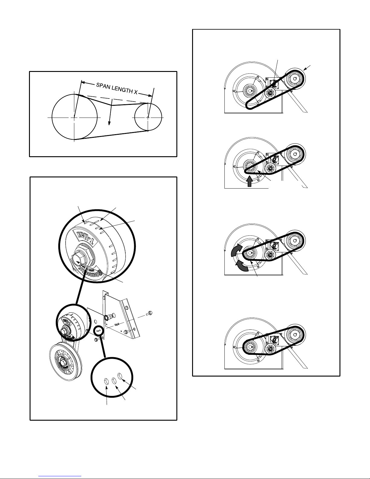
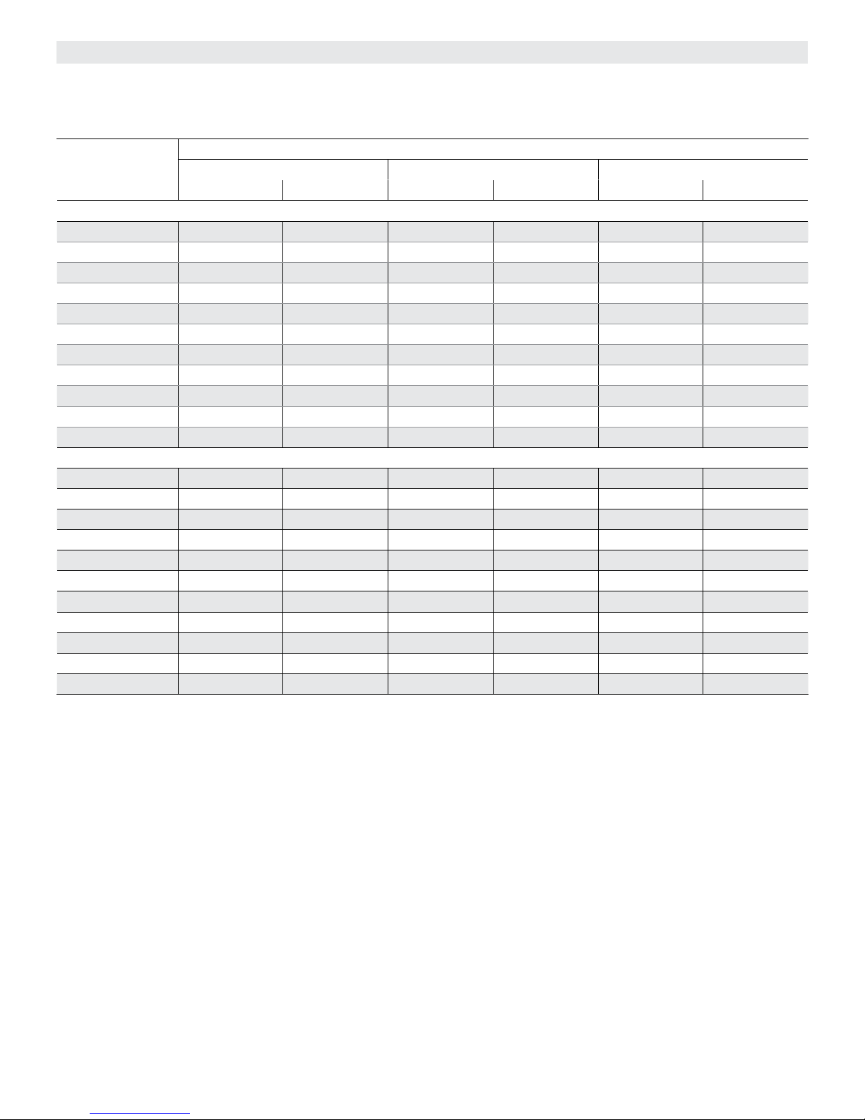
5- The blower RPM can be adjusted at the motor pulley.
Loosen Allen screw and turn adjustable pulley
clockwise to increase CFM. Turn counterclockwise to
decrease CFM. See figure 19. Do not exceed
minimum and maximum number of pulley turns as
shown in table 4.
6- KGB/KCB074 Unit Only -
If low speed during ventilation is desired, replace
J351 connector with J350.
TABLE 4
MINIMUM AND MAXIMUM PULLEY ADJUSTMENT
Belt Min. Turns Open Maxi. Turns Open
A Section No minimum 5
D-Blower Belt Adjustment
Maximum life and wear can be obtained from belts only
if proper pulley alignment and belt tension are
maintained. Tension new belts after a 24-48 hour
period of operation. This will allow belt to stretch and
seat grooves. Make sure blower and motor pulley are
aligned as shown in figure 20.
KG/KC 024, 030, 036, 048, 060, 072, 074, 090
Page 12
Page 13

BLOWER ASSEMBLY
TO INCREASE CFM
LOOSEN ALLEN SCREW &
TURN PULLEY CLOCKWISE
SIDE VIEW
MOTOR
TO INCREASE BELT TENSION
1-Loosen four bolts securing motor base to mounting
frame.
2-Slide the motor downward to tighten the belt.
3-Tighten four bolts on motor base.
TO DECREASE CFM
TURN PULLEY
COUNTERCLOCKWISE
ALLEN
SCREW
PULLEY
LOOSEN ALLEN
SCREW TO
ADJUST CFM
LOOSEN FOUR BOLTS AND
SLIDE BLOWER MOTOR
DOWNWARD TO TIGHTEN BELT
FIGURE 19
1- Loosen four bolts securing motor base to mounting
frame. See figure 19.
2- To increase belt tension -
Slide blower motor downward to tighten the belt. This
increases the distance between the blower motor and
the blower housing.
3- To loosen belt tension -
Slide blower motor upward to loosen the belt. This
decreases the distance between the blower motor
and the blower housing.
4- Tighten four bolts securing motor base to the
mounting frame.
E-Blower Belt Adjustment - M Volt Units With 3 HP
Blowers Equipped With A Belt Tensioner
1- Remove blower belt.
PULLEY ALIGNMENT
ALIGNED
2- Remove bracket from blower housing. See figure 22.
3- Remove the screw from the back side of the bracket.
4- Move the tensioner to the appropriate adjustment
hole and reinstall screw.
5- Replace bracket.
6- Replace blower belt. See figure 23.
F-Check Belt Tension - Units Not Equipped With A
Belt Tensioner
Overtensioning belts shortens belt and bearing life.
Check belt tension as follows:
1- Measure span length X. See figure 21.
2- Apply perpendicular force to center of span (X) with
enough pressure to deflect belt 1/64” for every inch
of span length or 1.5mm per 100mm of span length.
Example: Deflection distance of a 40” span would be
40/64” or 5/8”.
Example: Deflection distance of a 400mm span
would be 6mm.
MOTOR
PULLEY
BELT
NOT ALIGNED
FIGURE 20
BLOWER
PULLEY
3- Measure belt deflection force. For a used belt, the
deflection force should be 5 lbs. (35kPa). A new belt
deflection force should be 7 lbs. (48kPa).
A force below these values indicates an
undertensioned belt. A force above these values
indicates an overtensioned belt.
Page 13
507348-04 12/2015
Page 14
G-Field-Furnished Blower Drives
For field-furnished blower drives, use belt drive blower
tables to determine BHP and RPM required. Reference
the drive kit specification table and manufacturer's drive
number table.
MEASURE BELT TENSION
INSTALL BELT
TENSIONER
1
DRIVER
PULLEY
FORCE
DEFLECTION 1/64” PER INCH OF SPAN
OR 1.5mm PER 100mm OF SPAN
FIGURE 21
ADJUST BELT TENSIONER
MAXIMUM
TENSION
INDICATOR SHOULD BE
BETWEEN MINIMUM AND
MAXIMUM TENSION LINES
MINIMUM
TENSION
TIGHTEN MOUNTING
BOLT TO 22 LB./FT.
USING 9/16” WRENCH
2
DRIVEN
PULLEY
3
ROTATE DRIVEN
PULLEY TO SEAT BELT
BRACKET
TENSIONER
FACTORY-SET
POSITION
BELT POSITION
FIGURE 22
KG/KC 024, 030, 036, 048, 060, 072, 074, 090
TIGHTEST
BELT
POSITION
TIGHTER
4
FIGURE 23
Page 14
Page 15

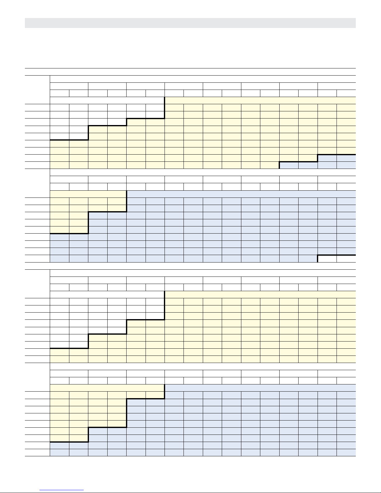
BLOWER DATA - DIRECT DRIVE - KGB024
BLOWER TABLE INCLUDES RESISTANCE FOR BASE UNIT ONLY WITH DRY INDOOR COIL AND AIR FILTERS IN PLACE.
FOR ALL UNITS ADD:
1 - Any factory installed options air resistance (larger gas heat section, economizer, wet coil, etc.) See page 41.
2 - Any eld installed accessories air resistance (duct resistance, diffuser, etc.) See page 41.
External Static
Pressure (in. w.g.)
High Medium Low High Medium Low
2 Ton Standard Efciency (Downow) KGB024S
0.0 1275 979 878 1453 1140 926
0.1 1262 960 834 1440 1124 912
0.2 1243 938 790 1420 1096 884
0.3 1218 909 746 1396 1065 853
0.4 1186 866 710 1352 1033 822
0.5 1137 838 657 1316 986 774
0.6 1104 795 604 1263 954 727
0.7 1055 752 534 1210 906 680
0.8 990 694 463 1158 859 632
0.9 925 637 392 1070 764 538
1.0 794 523 290 928 669 477
2 Ton Standard Efciency (Horizontal) KGB024S
0.0 1204 937 818 1370 1098 879
0.1 1186 913 788 1352 1066 864
0.2 1164 882 748 1327 1034 839
0.3 1137 860 710 1300 1001 809
0.4 1104 818 670 1263 968 768
0.5 1070 775 612 1227 925 728
0.6 1031 733 554 1190 881 688
0.7 991 690 500 1136 816 628
0.8 937 626 432 1081 751 557
0.9 804 566 362 1009 665 492
1.0 678 497 287 900 565 416
208 VOLTS 230 VOLTS
Air Volume (cfm) at Various Blower Speeds
Page 15
Page 16

BLOWER DATA - DIRECT DRIVE - KGB030
BLOWER TABLE INCLUDES RESISTANCE FOR BASE UNIT ONLY WITH DRY INDOOR COIL AND AIR FILTERS IN PLACE.
FOR ALL UNITS ADD:
1 - Any factory installed options air resistance (larger gas heat section, economizer, wet coil, etc.) See page 41.
2 - Any eld installed accessories air resistance (duct resistance, diffuser, etc.) See page 41.
External Static
Pressure (in. w.g.)
High Medium Low High Medium Low
2.5 Ton Standard Efciency (Downow) KGB030S
0.0 1211 949 852 1365 1097 916
0.1 1251 946 826 1422 1099 908
0.2 1241 952 794 1419 1112 893
0.3 1234 915 749 1419 1074 861
0.4 1213 880 702 1402 1038 824
0.5 1178 846 661 1366 1003 795
0.6 111 8 790 585 1302 942 720
0.7 1054 751 518 1231 900 655
0.8 964 675 460 1130 815 600
0.9 882 626 368 1037 762 501
1.0 729 494 286 859 606 412
2.5 Ton Standard Efciency (Horizontal) KGB030S
0.0 1163 930 815 1312 1075 875
0.1 1173 912 783 1333 1060 861
0.2 1169 888 746 1337 1037 839
0.3 1152 858 704 1325 1007 809
0.4 1122 822 657 1297 969 772
0.5 1079 779 606 1252 923 728
0.6 1023 730 549 1191 870 676
0.7 953 674 488 1114 808 617
0.8 871 613 422 1020 739 550
0.9 775 545 350 911 662 476
1.0 666 470 274 785 578 395
208 VOLTS 230 VOLTS
Air Volume (cfm) at Various Blower Speeds
Page 16
Page 17

BLOWER DATA - DIRECT DRIVE - KGA/KGB036, KGA/KGB048
BLOWER TABLE INCLUDES RESISTANCE FOR BASE UNIT ONLY WITH DRY INDOOR COIL AND AIR FILTERS IN PLACE.
FOR ALL UNITS ADD:
1 - Any factory installed options air resistance (larger gas heat section, economizer, wet coil, etc.) See page 41.
2 - Any eld installed accessories air resistance (duct resistance, diffuser, etc.) See page 41.
External Static
Pressure (in. w.g.)
High Medium Low High Medium Low High Medium Low
3 and 4 Ton Standard Efciency (Downow) KGA/KGB036S and KGA/KGB048S
0.0 1873 1561 1123 2094 1783 1321 2064 1727 1216
0.1 1993 1601 1148 2168 1797 1338 2105 1744 1229
0.2 1913 1601 1137 2098 1803 1308 2050 1694 1198
0.3 1858 1527 1078 2036 1725 1261 1987 1638 1167
0.4 1801 1496 1046 1973 1679 1219 1905 1598 1148
0.5 1763 1467 987 1910 1647 1177 1862 1559 1108
0.6 1709 1414 897 1830 1560 1080 1781 1509 1057
0.7 1617 1368 806 1727 1519 986 1698 1449 982
0.8 1472 1269 730 1604 1419 918 1614 1389 920
0.9 1359 1162 487 1478 1363 706 1488 1346 792
1.0 961 922 370 1093 1083 590 1167 1099 703
3 and 4 Ton Standard Efciency (Horizontal) KGA/KGB036S and KGA/KGB048S
0.0 1799 1530 1073 2012 1747 1263 2015 1756 1251
0.1 1868 1544 1088 2032 1733 1268 2071 1760 1279
0.2 1802 1494 1068 1976 1682 1228 2014 1700 1226
0.3 1735 1432 1014 1900 1618 1185 1937 1634 1187
0.4 1666 1397 980 1825 1568 1142 1878 1597 1174
0.5 1615 1350 904 1750 1516 1078 1801 1558 1124
0.6 1564 1305 842 1675 1440 1014 1743 1479 1060
0.7 1462 1228 758 1562 1364 928 1664 1415 982
0.8 1330 1151 670 1449 1287 842 1512 1335 865
0.9 1194 1011 464 1298 1185 671 1393 1297 733
1.0 878 878 355 998 1032 565 1060 1063 618
208 VOLTS 230 VOLTS 460/575 VOLTS
Air Volume (cfm) at Various Blower Speeds
Page 17
Page 18
BLOWER DATA - DIRECT DRIVE - KGA060
BLOWER TABLE INCLUDES RESISTANCE FOR BASE UNIT ONLY WITH DRY INDOOR COIL AND AIR FILTERS IN PLACE.
FOR ALL UNITS ADD:
1 - Any factory installed options air resistance (larger gas heat section, economizer, wet coil, etc.) See page 41.
2 - Any eld installed accessories air resistance (duct resistance, diffuser, etc.) See page 41.
External Static
Pressure (in. w.g.)
5 Ton Standard Efciency (Downow) KGA060S
0.0 2200 1649 2411 1957 2241 1755
0.1 2256 1669 2417 2002 2221 1742
0.2 2202 1739 2396 1985 2193 1747
0.3 2170 1705 2328 1972 2144 1725
0.4 2158 1689 2293 1959 2104 1695
0.5 2130 1676 2279 1930 2086 1678
0.6 2056 1662 2158 1900 2008 1652
0.7 2032 1657 2089 1857 1975 1610
0.8 1963 1591 2077 1796 1941 1586
0.9 1887 1597 1876 1746 1855 1555
1.0 1695 1400 1746 1601 1778 1486
5 Ton Standard Efciency (Horizontal) KGA060S
0.0 2114 1615 2305 1880 2308 1890
0.1 2115 1610 2290 1876 2334 1906
0.2 2074 1622 2249 1870 2292 1890
0.3 2025 1599 2188 1841 2230 1859
0.4 1996 1577 2148 1812 2210 1846
0.5 1952 1542 2087 1768 2148 1817
0.6 1882 1534 2026 1739 2108 1786
0.7 1838 1488 1966 1680 2094 1743
0.8 1773 1443 1905 1622 1988 1682
0.9 1657 1389 1784 1534 1915 1679
1.0 1548 1335 1672 1462 1853 1506
208 VOLTS 230 VOLTS 460/575 VOLTS
High Low High Low High Low
Air Volume (cfm) at Various Blower Speeds
Page 18
Page 19

BLOWER DATA - DIRECT DRIVE - KGB060
BLOWER TABLE INCLUDES RESISTANCE FOR BASE UNIT ONLY WITH DRY INDOOR COIL AND AIR FILTERS IN PLACE.
FOR ALL UNITS ADD:
1 - Any factory installed options air resistance (larger gas heat section, economizer, wet coil, etc.) See page 41.
2 - Any eld installed accessories air resistance (duct resistance, diffuser, etc.) See page 41.
External Static
Pressure (in. w.g.)
5 Ton Standard Efciency (Downow) KGB060S
0.0 1940 1581 2131 1788 2131 1788
0.1 1929 1566 2107 1784 2107 1784
0.2 1906 1552 2074 1774 2074 1774
0.3 1872 1546 2036 1752 2036 1752
0.4 1836 1526 1998 1708 1998 1708
0.5 1802 1486 1960 1679 1960 1679
0.6 1749 1447 1904 1635 1904 1635
0.7 1714 1407 1847 1576 1847 1576
0.8 1644 1347 1771 1518 1771 1518
0.9 1574 1245 1658 1430 1658 1430
1.0 1338 - - - 1506 - - - 1506 - - -
5 Ton Standard Efciency (Horizontal) KGB060S
0.0 1930 1575 2143 1764 2143 1764
0.1 1920 1573 2115 1761 2115 1761
0.2 1910 1576 2088 1751 2088 1751
0.3 1870 1552 2055 1746 2055 1746
0.4 1840 1524 2023 1704 2023 1704
0.5 1790 1495 1979 1675 1979 1675
0.6 1739 1466 1925 1633 1925 1633
0.7 1679 1428 1860 1590 1860 1590
0.8 1639 1371 1775 1534 1775 1534
0.9 1559 1270 1670 1421 1670 1421
1.0 1438 - - - 1539 1285 1539 1285
208 VOLTS 230 VOLTS 460/575 VOLTS
High Low High Low High Low
Air Volume (cfm) at Various Blower Speeds
Page 19
Page 20

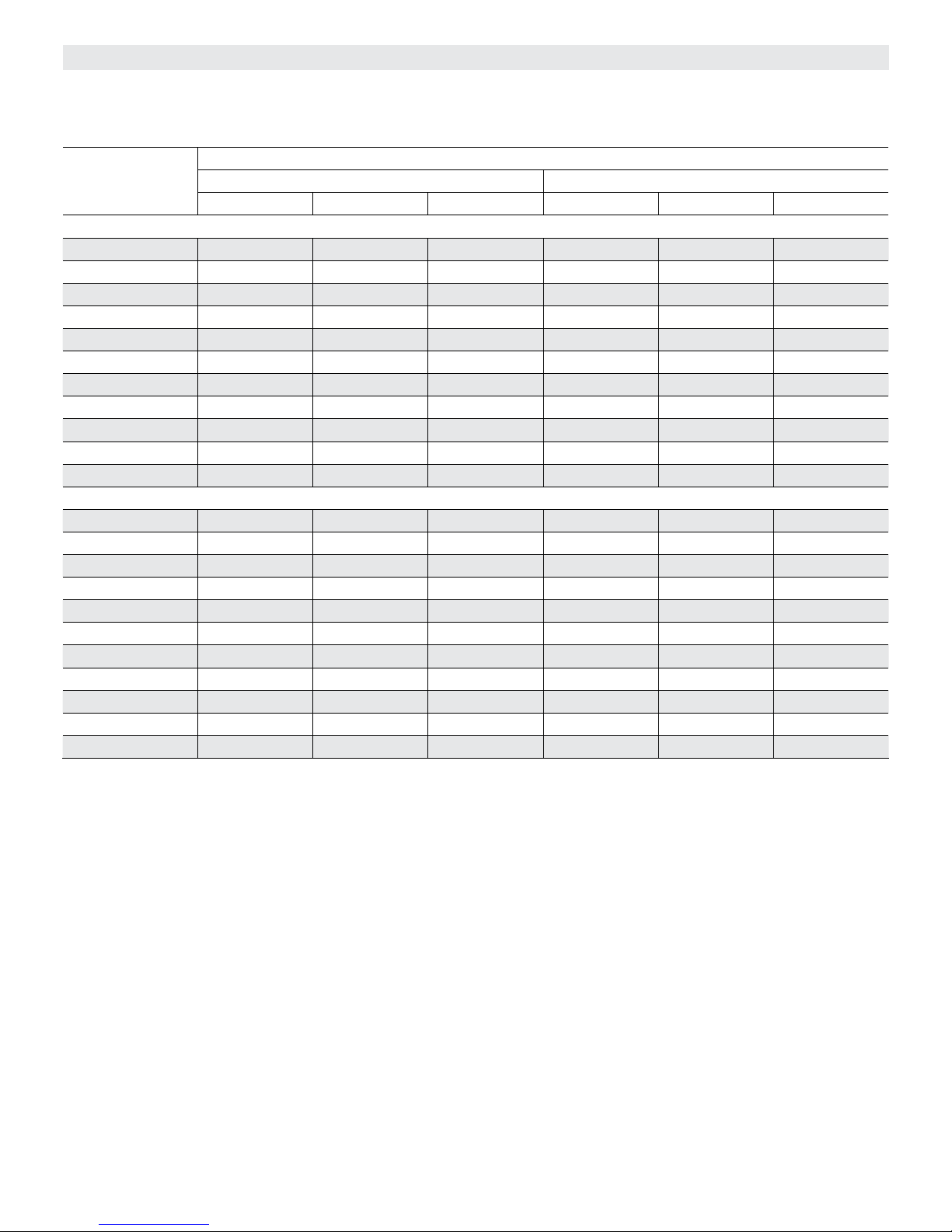
BLOWER DATA - BELT DRIVE - KGA/KGB036
BLOWER TABLE INCLUDES RESISTANCE FOR BASE UNIT ONLY WITH DRY INDOOR COIL AND AIR FILTERS IN PLACE.
FOR ALL UNITS ADD:
1 - Any factory installed options air resistance (heat section, economizer, wet coil, etc.).
2 - Any eld installed accessories air resistance (duct resistance, diffuser, etc.).
See page 41 for blower motors and drives and wet coil and options/accessory air resistance data.
DOWNFLOW
Air
Volume
cfm
900 493 0.11 564 0.15 637 0.19 711 0.22 783 0.24 851 0.26 910 0.29 961 0.32
1000 517 0.14 588 0.18 660 0.22 733 0.24 804 0.26 868 0.29 924 0.32 974 0.35
1100 544 0.17 614 0.21 685 0.25 757 0.27 826 0.29 887 0.32 940 0.36 987 0.38
1200 574 0.2 643 0.24 712 0.28 782 0.31 849 0.33 906 0.36 956 0.39 1001 0.42
1300 613 0.23 679 0.28 745 0.31 811 0.34 873 0.36 926 0.40 973 0.43 1016 0.46
1400 662 0.26 722 0.30 781 0.34 841 0.37 897 0.41 944 0.44 989 0.48 1032 0.51
1500 710 0.29 763 0.33 816 0.38 869 0.41 919 0.45 963 0.49 1006 0.53 1049 0.56
Air
Volume
cfm
900 1008 0.34 1056 0.36 1104 0.39 1149 0.41 1190 0.44 1229 0.46 1267 0.49 1305 0.52
1000 1020 0.37 1067 0.40 1115 0.42 1159 0.45 1200 0.48 1239 0.51 1277 0.54 1314 0.57
1100 1032 0.41 1078 0.43 1124 0.46 1168 0.49 1210 0.52 1249 0.55 1286 0.58 1323 0.62
1200 1045 0.45 1090 0.47 1135 0.50 1178 0.53 1220 0.57 1259 0.60 1296 0.64 1332 0.67
1300 1060 0.49 1104 0.51 1148 0.55 1190 0.58 1230 0.62 1269 0.65 1306 0.69 1342 0.72
1400 1075 0.53 1119 0.56 1162 0.60 1203 0.63 1242 0.67 1280 0.71 1317 0.75 1352 0.78
1500 1093 0.58 1136 0.61 1177 0.65 1217 0.69 1255 0.73 1292 0.77 1328 0.80 1364 0.84
HORIZONTAL
Air
Volume
cfm
900 465 0.09 531 0.14 600 0.17 670 0.20 740 0.22 808 0.24 869 0.27 925 0.30
1000 483 0.12 549 0.16 617 0.20 687 0.22 756 0.24 822 0.26 881 0.29 935 0.33
1100 504 0.14 570 0.19 637 0.22 706 0.25 773 0.27 837 0.29 894 0.32 946 0.36
1200 527 0.17 592 0.22 658 0.25 726 0.28 792 0.30 854 0.32 908 0.36 957 0.39
1300 552 0.20 617 0.25 682 0.29 748 0.31 812 0.33 871 0.36 923 0.40 970 0.43
1400 580 0.24 644 0.28 708 0.32 773 0.35 834 0.37 890 0.40 938 0.44 984 0.48
1500 6
Air
Volume
cfm
900 977 0.33 1028 0.36 1079 0.39 1127 0.42 1169 0.45 1208 0.48 1246 0.51 1282 0.54
1000 985 0.36 1036 0.39 1087 0.42 1135 0.45 1177 0.48 1216 0.52 1253 0.55 1290 0.58
1100 995 0.39 1044 0.42 1093 0.45 1140 0.49 1183 0.52 1223 0.56 1261 0.59 1297 0.62
1200 1005 0.43 1053 0.46 1100 0.49 1146 0.53 1190 0.56 1230 0.60 1268 0.63 1304 0.67
1300 1016 0.47 1063 0.50 1109 0.53 1154 0.57 1197 0.61 1237 0.64 1275 0.68 1311 0.72
1400 1029 0.51 1074 0.54 1120 0.58 1164 0.61 1205 0.65 1245 0.69 1282 0.73 1318 0.77
1500 1042 0.56 1087 0.59 1132 0.62 1174 0.66 1215 0.71 1253 0.75 1290 0.78 1326 0.82
0.10 0.20 0.30 0.40 0.50 0.60 0.70 0.80
RPM BHP RPM BHP RPM BHP RPM BHP RPM BHP RPM BHP RPM BHP RPM BHP
Field Furnished Kit A01
0.90 1.00 1.10 1.20 1.30 1.40 1.50 1.60
RPM BHP RPM BHP RPM BHP RPM BHP RPM BHP RPM BHP RPM BHP RPM BHP
Kit A01 Kit A05
0.10 0.20 0.30 0.40 0.50 0.60 0.70 0.80
RPM BHP RPM BHP RPM BHP RPM BHP RPM BHP RPM BHP RPM BHP RPM BHP
Field Furnished Kit A01
11 0.28 674 0.32 736 0.35 799 0.38 857 0.41 908 0.44 954 0.49 998 0.52
0.90 1.00 1.10 1.20 1.30 1.40 1.50 1.60
RPM BHP RPM BHP RPM BHP RPM BHP RPM BHP RPM BHP RPM BHP RPM BHP
Kit A01 Kit A05
External Static - in. w.g.
External Static - in. w.g.
External Static - in. w.g.
External Static - in. w.g.
Page 20
Page 21
BLOWER DATA - BELT DRIVE - KGA/KGB048
BLOWER TABLE INCLUDES RESISTANCE FOR BASE UNIT ONLY WITH DRY INDOOR COIL AND AIR FILTERS IN PLACE.
FOR ALL UNITS ADD:
1 - Any factory installed options air resistance (heat section, economizer, wet coil, etc.).
2 - Any eld installed accessories air resistance (duct resistance, diffuser, etc.).
See page 41 for blower motors and drives and wet coil and options/accessory air resistance data.
DOWNFLOW
Air
Volume
cfm
1200 574 0.20 644 0.24 713 0.28 784 0.31 850 0.33 906 0.36 953 0.39 998 0.42
1300 608 0.24 677 0.28 744 0.31 813 0.34 874 0.37 925 0.40 969 0.43 1014 0.46
1400 645 0.28 712 0.31 778 0.35 842 0.38 898 0.41 944 0.44 986 0.48 1030 0.51
1500 684 0.31 749 0.35 811 0.38 871 0.42 921 0.45 963 0.49 1004 0.53 1048 0.56
1600 723 0.35 785 0.39 844 0.43 898 0.46 943 0.50 983 0.54 1024 0.58 1067 0.61
1700 761 0.40 819 0.44 875 0.48 924 0.52 965 0.56 1004 0.60 1045 0.63 1089 0.66
1800 798 0.45 853 0.49 905 0.54 950 0.58 990 0.62 1028 0.66 1069 0.69 111 2 0.72
1900 834 0.51 885 0.55 934 0.60 977 0.64 1015 0.68 1054 0.72 1095 0.75 1137 0.79
2000 869 0.57 917 0.62 962 0.67 1004 0.71 1042 0.75 1081 0.78 1121 0.82 1162 0.86
Air
Volume
cfm
1200 1043 0.44 1090 0.47 1135 0.50 1179 0.53 1220 0.57 1259 0.60 1297 0.64 1333 0.67
1300 1058 0.49 1104 0.51 1148 0.55 1190 0.58 1231 0.62 1269 0.65 1306 0.69 1342 0.72
1400 1074 0.53 1119 0.56 1162 0.59 1203 0.63 1242 0.67 1280 0.71 1317 0.74 1352 0.78
1500 1092 0.58 1136 0.61 1177 0.65 1217 0.69 1255 0.73 1292 0.76 1328 0.80 1364 0.84
1600 111 2 0.63 1154 0.67 1193 0.71 1232 0.75 1269 0.79 1306 0.83 1341 0.87 1377 0.91
1700 1132 0.69 1173 0.73 1211 0.77 1248 0.81 1285 0.86 1321 0.90 1356 0.94 1391 0.98
1800 1154 0.76 1194 0.80 1230 0.85 1266 0.89 1302 0.93 1338 0.98 1373 1.02 1408 1.06
1900 1178 0.83 1215 0.88 1250 0.93 1286 0.98 1321 1.02 1356 1.06 1391 1.10 1426 1.14
2000 1201 0.91 1237 0.97 1271 1.02 1307 1.07 1342 1.11 1376 1.15 1411 1.19 1446 1.23
HORIZONTAL
Air
Volume
cfm
1200 540 0.18 606 0.22 673 0.26 748 0.29 816 0.30 870 0.33 914 0.37 961 0.40
1300 568 0.21 634 0.26 699 0.29 771 0.32 835 0.34 886 0.37 929 0.41 975 0.44
1400 599 0.25 664 0.29 728 0.33 795 0.35 855 0.38 903 0.41 946 0.45 991 0.49
1500 632 0.29 696 0.33 758 0.36 821 0.39 877 0.42 922 0.46 963 0.50 1008 0.54
1600 667 0.33 729 0.36 789 0.40 848 0.43 898 0.46 941 0.51 982 0.55 1026 0.59
1700 702 0.36 761 0.40 819 0.44 873 0.48 920 0.52 960 0.56 1001 0.61 1044 0.64
1800 737 0.41 794 0.45 848 0.49 898 0.53 941 0.58 981 0.62 1021 0.66 1064 0.70
1900 771 0.46 825 0.50 877 0.54 923 0.59 964 0.64 1002 0.68 1043 0.72 1085 0.76
2000 805 0.51 857 0.56 905 0.61 948 0.66 987 0.71 1025 0.75 1065 0.79 1
Air
Volume
cfm
1200 1010 0.43 1061 0.46 1110 0.50 1156 0.53 1199 0.57 1239 0.61 1276 0.64 1312 0.68
1300 1024 0.47 1073 0.50 1120 0.54 1165 0.58 1207 0.62 1246 0.65 1284 0.69 1320 0.73
1400 1038 0.52 1086 0.55 1131 0.59 1175 0.62 1216 0.66 1255 0.70 1292 0.74 1328 0.78
1500 1054 0.57 1100 0.60 1144 0.64 1186 0.68 1226 0.72 1264 0.75 1301 0.79 1336 0.83
1600 1071 0.62 1116 0.65 1158 0.69 1198 0.73 1237 0.77 1274 0.81 1310 0.85 1345 0.89
1700 1089 0.67 1132 0.71 1172 0.75 1211 0.79 1249 0.83 1285 0.87 1321 0.91 1355 0.95
1800 1108 0.73 1149 0.77 1188 0.81 1225 0.85 1262 0.90 1298 0.94 1332 0.98 1366 1.01
1900 1128 0.79 1167 0.84 1204 0.88 1241 0.92 1276 0.97 1311 1.01 1345 1.05 1379 1.09
2000 1148 0.86 1186 0.91 1221 0.96 1257 1.00 1292 1.05 1326 1.09 1359 1.13 1393 1.17
0.10 0.20 0.30 0.40 0.50 0.60 0.70 0.80
RPM BHP RPM BHP RPM BHP RPM BHP RPM BHP RPM BHP RPM BHP RPM BHP
Field Furnished Kit A02
0.90 1.00 1.10 1.20 1.30 1.40 1.50 1.60
RPM BHP RPM BHP RPM BHP RPM BHP RPM BHP RPM BHP RPM BHP RPM BHP
Kit A02 Kit A06
0.10 0.20 0.30 0.40 0.50 0.60 0.70 0.80
RPM BHP RPM BHP RPM BHP RPM BHP
Field Furnished Kit A02
0.90 1.00 1.10 1.20 1.30 1.40 1.50 1.60
RPM BHP RPM BHP RPM BHP RPM BHP RPM BHP RPM BHP RPM BHP RPM BHP
Kit A02 Kit A06
External Static - in. w.g.
External Static - in. w.g.
External Static - in. w.g.
RPM BHP RPM BHP RPM BHP RPM BHP
107 0.82
External Static - in. w.g.
Page 21
Page 22

BLOWER DATA - BELT DRIVE - KGA060
BLOWER TABLE INCLUDES RESISTANCE FOR BASE UNIT ONLY WITH DRY INDOOR COIL AND AIR FILTERS IN PLACE.
FOR ALL UNITS ADD:
1 - Any factory installed options air resistance (heat section, economizer, wet coil, etc.).
2 - Any eld installed accessories air resistance (duct resistance, diffuser, etc.).
See page 41 for blower motors and drives and wet coil and options/accessory air resistance data.
DOWNFLOW
Air
Volume
cfm
1600 745 0.36 805 0.40 862 0.44 913 0.48 956 0.52 996 0.55 1037 0.59 1081 0.62
1700 783 0.41 840 0.45 893 0.49 940 0.53 980 0.57 1019 0.61 1061 0.64 1104 0.67
1800 820 0.47 873 0.51 923 0.55 967 0.60 1006 0.63 1045 0.67 1086 0.70 1129 0.73
1900 856 0.52 906 0.57 953 0.62 994 0.66 1032 0.70 1071 0.73 1112 0.76 1154 0.80
2000 891 0.59 937 0.64 982 0.69 1022 0.73 1060 0.76 1099 0.80 1140 0.84 1180 0.88
2100 924 0.66 968 0.71 1011 0.75 1051 0.79 1089 0.83 1128 0.87 1167 0.92 1206 0.97
2200 956 0.74 999 0.78 1041 0.83 1080 0.87 111 9 0.91 1157 0.96 1196 1.02 1233 1.08
2300 990 0.81 1032 0.86 1072 0.91 1111 0.95 1149 1.00 1187 1.06 1225 1.13 1261 1.19
2400 1025 0.90 1066 0.95 1105 1.00 1143 1.05 1181 1.11 1218 1.17 1255 1.24 1290 1.30
Air
Volume
cfm
1600 1125 0.64 1167 0.68 1206 0.72 1244 0.76 1281 0.80 1317 0.84 1353 0.88 1388 0.92
1700 1147 0.70 1187 0.75 1224 0.79 1261 0.83 1298 0.87 1333 0.91 1369 0.95 1404 0.99
1800 1170 0.77 1208 0.82 1244 0.87 1280 0.91 1316 0.95 1351 0.99 1386 1.03 1422 1.07
1900 1194 0.85 1230 0.90 1265 0.95 1301 1.00 1336 1.04 1371 1.08 1406 1.12 1441 1.16
2000 1218 0.94 1253 1.00 1287 1.05 1323 1.09 1358 1.14 1392 1.17 1427 1.21 1463 1.25
2100 1243 1.03 1277 1.09 1311 1.15 1346 1.19 1381 1.23 1415 1.27 1450 1.31 1486 1.34
2200 1268 1.14 1302 1.20 1336 1.25 1371 1.29 1405 1.33 1439 1.37 1474 1.40 1511 1.44
2300 1295 1.25 1328 1.30 1362 1.35 1397 1.39 1431 1.43 1465 1.47 1500 1.50 1537 1.54
2400 1324 1.36 1356 1.41 1390 1.46 1424 1.50 1458 1.53 1492 1.57 1527 1.61 1563 1.64
HORIZONTAL
Air
Volume
cfm
1600 690 0.33 751 0.37 810 0.40 865 0.44 912 0.48 955 0.52 997 0.56 1041 0.60
1700 725 0.38 784 0.41 839 0.45 891 0.49 935 0.53 975 0.58 1017 0.62 1060 0.65
1800 761 0.42 816 0.46 868 0.50 916 0.55 957 0.59 997 0.64 1038 0.68 1081 0.71
1900 795 0.48 848 0.52 897 0.56 942 0.61 981 0.66 1020 0.70 1060 0.74 1
2000 830 0.53 879 0.58 926 0.63 968 0.68 1006 0.73 1044 0.77 1084 0.80 1126 0.84
2100 863 0.60 910 0.65 954 0.70 994 0.75 1032 0.80 1070 0.83 1110 0.87 1150 0.91
2200 895 0.67 939 0.73 982 0.78 1021 0.83 1058 0.87 1096 0.91 1135 0.95 1174 1.00
2300 926 0.75 969 0.81 1009 0.86 1048 0.90 1085 0.94 1122 0.99 1160 1.04 1197 1.09
2400 957 0.84 998 0.89 1038 0.94 1076 0.98 111 2 1.03 1149 1.08 1185 1.14 1221 1.20
Air
Volume
cfm
1600 1086 0.63 1129 0.66 1171 0.70 1211 0.74 1249 0.78 1286 0.82 1321 0.86 1356 0.90
1700 1104 0.68 1147 0.72 1186 0.76 1225 0.80 1262 0.84 1298 0.88 1333 0.92 1367 0.96
1800 1124 0.74 1165 0.79 1202 0.83 1240 0.87 1276 0.91 1311 0.95 1345 0.99 1380 1.03
1900 1145 0.81 1183 0.85 1220 0.90 1256 0.94 1291 0.99 1326 1.03 1360 1.07 1393 1.10
2000 1167 0.88 1203 0.93 1237 0.98 1273 1.03 1307 1.07 1341 1.11 1375 1.15 1408 1.18
2100 1188 0.96 1222 1.02 1256 1.07 1291 1.12 1324 1.16 1358 1.20 1391 1.23 1424 1.27
2200 1210 1.05 1243 1.11 1275 1.17 1309 1.21 1343 1.25 1376 1.29 1409 1.33 1442 1.36
2300 1232 1.16 1263 1.22 1295 1.27 1329 1.31 1362 1.35 1395 1.39 1428 1.42 1462 1.45
2400 1254 1.26 1284 1.32 1317 1.37 1350 1.41 1383 1.45 1415 1.48 1448 1.52 1483 1.55
0.10 0.20 0.30 0.40 0.50 0.60 0.70 0.80
RPM BHP RPM BHP RPM BHP RPM BHP RPM BHP RPM BHP RPM BHP RPM BHP
Field Furnished Kit A03
0.90 1.00 1.10 1.20 1.30 1.40 1.50 1.60
RPM BHP RPM BHP RPM BHP RPM BHP RPM BHP RPM BHP RPM BHP RPM BHP
Kit A03 Kit A07
0.10 0.20 0.30 0.40 0.50 0.60 0.70 0.80
RPM BHP RPM BHP RPM BHP RPM BHP
Field Furnished Kit A03
0.90 1.00 1.10 1.20 1.30 1.40 1.50 1.60
RPM BHP RPM BHP RPM BHP RPM BHP RPM BHP RPM BHP RPM BHP RPM BHP
Kit A03 Kit A07
External Static - in. w.g.
External Static - in. w.g.
External Static - in. w.g.
RPM BHP RPM BHP RPM BHP RPM BHP
103 0.77
External Static - in. w.g.
Page 22
Page 23

BLOWER DATA - BELT DRIVE - KGB060
BLOWER TABLE INCLUDES RESISTANCE FOR BASE UNIT ONLY WITH DRY INDOOR COIL AND AIR FILTERS IN PLACE.
FOR ALL UNITS ADD:
1 - Any factory installed options air resistance (heat section, economizer, wet coil, etc.).
2 - Any eld installed accessories air resistance (duct resistance, diffuser, etc.).
See page 41 for blower motors and drives and wet coil and options/accessory air resistance data.
DOWNFLOW
Air
Volume
cfm
1600 720 0.28 769 0.33 819 0.37 871 0.41 926 0.44 975 0.47 1016 0.51 1054 0.55
1700 779 0.30 822 0.35 864 0.39 908 0.44 953 0.48 995 0.52 1034 0.57 1072 0.61
1800 828 0.34 864 0.39 901 0.43 938 0.48 977 0.53 1015 0.58 1053 0.63 1091 0.67
1900 858 0.41 892 0.45 927 0.50 962 0.55 999 0.60 1036 0.65 1074 0.69 111 2 0.73
2000 879 0.47 913 0.52 948 0.56 984 0.61 1020 0.67 1058 0.72 1096 0.76 1134 0.80
2100 900 0.53 935 0.58 970 0.63 1007 0.69 1044 0.74 1081 0.79 1119 0.84 1157 0.88
2200 922 0.60 958 0.65 994 0.71 1031 0.76 1068 0.82 1106 0.87 1143 0.91 1180 0.95
2300 947 0.67 983 0.73 1020 0.79 1057 0.85 1094 0.90 1131 0.95 1168 1.00 1205 1.03
2400 974 0.76 1010 0.82 1047 0.88 1084 0.94 1120 0.99 1157 1.04 1193 1.08 1230 1.12
Air
Volume
cfm
1600 1093 0.60 1133 0.63 1173 0.67 1214 0.70 1253 0.73 1288 0.77 1318 0.81 1351 0.85
1700 1111 0.65 1150 0.69 1190 0.72 1230 0.76 1268 0.79 1301 0.83 1331 0.87 1363 0.92
1800 1130 0.71 1169 0.75 1208 0.78 1247 0.82 1285 0.86 1317 0.90 1345 0.94 1377 0.98
1900 1150 0.77 1188 0.81 1227 0.85 1267 0.88 1303 0.92 1333 0.97 1361 1.02 1392 1.06
2000 1172 0.84 1210 0.88 1248 0.92 1286 0.96 1321 1.00 1350 1.05 1377 1.10 1409 1.14
2100 1195 0.91 1233 0.95 1269 1.00 1306 1.04 1339 1.09 1367 1.14 1395 1.19 1426 1.23
2200 1218 0.99 1255 1.03 1290 1.09 1324 1.14 1356 1.19 1385 1.24 1413 1.28 1444 1.32
2300 1242 1.07 1277 1.13 1310 1.20 1343 1.26 1374 1.30 1403 1.34 1432 1.38 1464 1.42
2400 1267 1.16 1300 1.23 1332 1.31 1364 1.37 1394 1.41 1423 1.45 1453 1.48 1484 1.53
HORIZONTAL
Air
Volume
cfm
1600 654 0.28 712 0.32 769 0.36 825 0.39 879 0.43 933 0.47 982 0.50 1024 0.54
1700 703 0.31 756 0.35 807 0.39 858 0.43 906 0.47 955 0.51 999 0.55 1039 0.59
1800 752 0.34 798 0.38 844 0.43 889 0.48 933 0.52 977 0.57 1017 0.61 1056 0.65
1900 796 0.38 837 0.43 878 0.48 918 0.53 958 0.58 997 0.62 1036 0.67 1074 0.71
2000 833 0.43 870 0.48 907 0.54 943 0.59 980 0.64 1018 0.69 1055 0.73 1093 0.77
2100 864 0.50 897 0.55 931 0.60 966 0.65 1002 0.71 1038 0.76 1075 0.80 111
2200 887 0.57 920 0.62 953 0.67 988 0.73 1024 0.78 1060 0.83 1097 0.87 1135 0.90
2300 909 0.64 942 0.70 976 0.75 1011 0.81 1046 0.86 1083 0.91 1120 0.95 1157 0.98
2400 931 0.72 965 0.78 999 0.83 1035 0.89 1071 0.94 1108 0.99 1144 1.03 1181 1.07
Air
Volume
cfm
1600 1063 0.58 1101 0.61 1141 0.64 1181 0.67 1222 0.70 1261 0.73 1298 0.77 1333 0.81
1700 1078 0.63 1117 0.66 1156 0.69 1196 0.72 1235 0.75 1273 0.79 1309 0.83 1344 0.87
1800 1094 0.68 1133 0.72 1172 0.75 1211 0.78 1250 0.81 1287 0.85 1322 0.90 1355 0.94
1900 111 2 0.74 1151 0.77 1190 0.81 1228 0.84 1265 0.88 1301 0.92 1335 0.97 1367 1.01
2000 1131 0.80 1170 0.83 1208 0.87 1245 0.91 1281 0.96 1316 1.00 1349 1.04 1380 1.09
2100 1151 0.87 1189 0.90 1227 0.94 1263 0.99 1298 1.04 1331 1.08 1363 1.13 1394 1.17
2200 1173 0.94 1210 0.98 1246 1.02 1281 1.07 1315 1.12 1347 1.17 1379 1.22 1409 1.26
2300 1195 1.02 1231 1.06 1266 1.11 1300 1.16 1333 1.22 1364 1.27 1395 1.32 1424 1.36
2400 1217 1.10 1252 1.15 1286 1.20 1319 1.26 1351 1.32 1382 1.38 1411 1.43 1440 1.48
0.10 0.20 0.30 0.40 0.50 0.60 0.70 0.80
RPM BHP RPM BHP RPM BHP RPM BHP RPM BHP RPM BHP RPM BHP RPM BHP
Field Furnished Kit A03
0.90 1.00 1.10 1.20 1.30 1.40 1.50 1.60
RPM BHP RPM BHP RPM BHP RPM BHP RPM BHP RPM BHP RPM BHP RPM BHP
Kit A03 Kit A07
0.10 0.20 0.30 0.40 0.50 0.60 0.70 0.80
RPM BHP RPM BHP RPM BHP RPM BHP
Field Furnished Kit A03
0.90 1.00 1.10 1.20 1.30 1.40 1.50 1.60
RPM BHP RPM BHP RPM BHP RPM BHP RPM BHP RPM BHP RPM BHP RPM BHP
Kit A03 Kit A07
External Static - in. w.g.
External Static - in. w.g.
External Static - in. w.g.
RPM BHP RPM BHP RPM BHP RPM BHP
3 0.83
External Static - in. w.g.
Page 23
Page 24

BLOWER DATA - BELT DRIVE - DOWNFLOW - KGA072, KGB072 & 074
BLOWER TABLE INCLUDES RESISTANCE FOR BASE UNIT ONLY WITH DRY INDOOR COIL AND AIR FILTERS IN PLACE.
FOR ALL UNITS ADD:
1 - Any factory installed options air resistance (heat section, economizer, wet coil, etc.).
2 - Any eld installed accessories air resistance (duct resistance, diffuser, etc.).
See page 41 for blower motors and drives and wet coil and options/accessory air resistance data.
External Static - in. w.g.
Air
Volume
cfm
1900 857 0.41 892 0.45 927 0.50 962 0.55 999 0.60 1036 0.65 1074 0.69 111 2 0.73
2000 879 0.47 913 0.52 948 0.56 984 0.61 1020 0.67 1058 0.72 1096 0.76 1134 0.80
2100 900 0.53 935 0.58 970 0.63 1007 0.69 1044 0.74 1081 0.79 1119 0.84 1157 0.88
2200 922 0.60 958 0.65 994 0.71 1031 0.76 1068 0.82 1106 0.87 1143 0.91 1180 0.95
2300 947 0.67 983 0.73 1020 0.79 1057 0.85 1094 0.90 1131 0.95 1168 1.00 1205 1.03
2400 974 0.76 1010 0.82 1047 0.88 1084 0.94 1120 0.99 1157 1.04 1193 1.08 1230 1.12
2500 1002 0.85 1039 0.91 1075 0.97 1112 1.03 1148 1.08 1184 1.13 1220 1.17 1257 1.21
2600 1032 0.95 1068 1.01 1105 1.07 1141 1.13 1177 1.17 1213 1.22 1248 1.26 1284 1.31
2700 1062 1.05 1099 1.11 1136 1.17 1172 1.22 1207 1.27 1242 1.32 1277 1.37 1312 1.43
2800 1094 1.16 1131 1.22 1167 1.27 1202 1.32 1237 1.38 1271 1.43 1305 1.49 1339 1.56
2900 1127 1.26 1163 1.32 1198 1.38 1233 1.44 1267 1.50 1300 1.56 1334 1.64 1367 1.71
Air
Volume
cfm
1900 1150 0.77 1188 0.81 1227 0.85 1267 0.88 1303 0.92 1333 0.97 1360 1.02 1392 1.06
2000 1172 0.84 1210 0.88 1248 0.92 1286 0.96 1321 1.00 1350 1.05 1377 1.10 1409 1.14
2100 1195 0.91 1233 0.95 1269 1.00 1306 1.04 1339 1.09 1367 1.14 1395 1.19 1426 1.23
2200 1218 0.99 1255 1.03 1290 1.09 1324 1.14 1356 1.19 1385 1.24 1413 1.28 1444 1.32
2300 1242 1.07 1277 1.13 1310 1.20 1343 1.26 1374 1.30 1403 1.34 1432 1.38 1464 1.42
2400 1267 1.16 1300 1.23 1332 1.31 1364 1.37 1394 1.41 1423 1.45 1453 1.48 1484 1.53
2500 1292 1.26 1324 1.34 1355 1.42 1387 1.48 1417 1.52 1445 1.56 1475 1.59 1506 1.64
2600 1318 1.38 1350 1.46 1380 1.55 1411 1.60 1440 1.64 1469 1.68 1498 1.71 1529 1.76
2700 1345 1.51 1376 1.60 1406
2800 1372 1.65 1403 1.74 1433 1.82 1462 1.86 1490 1.90 1519 1.93 1548 1.97 1578 2.01
2900 1399 1.80 1430 1.89 1460 1.96 1489 2.00 1516 2.03 1544 2.06 1573 2.10 1603 2.14
0.10 0.20 0.30 0.40 0.50 0.60 0.70 0.80
RPM BHP RPM BHP RPM BHP RPM BHP RPM BHP RPM BHP RPM BHP RPM BHP
Field Furnished Kit A04
External Static - in. w.g.
0.90 1.00 1.10 1.20 1.30 1.40 1.50 1.60
RPM BHP RPM BHP RPM BHP RPM BHP RPM BHP RPM BHP RPM BHP RPM BHP
Kit A04 Kit A08
1.68 1436 1.73 1465 1.77 1493 1.80 1523 1.84 1553 1.88
Page 24
Page 25

BLOWER DATA - BELT DRIVE - HORIZONTAL - KGA072, KGB072 & 074
BLOWER TABLE INCLUDES RESISTANCE FOR BASE UNIT ONLY WITH DRY INDOOR COIL AND AIR FILTERS IN PLACE.
FOR ALL UNITS ADD:
1 - Any factory installed options air resistance (heat section, economizer, wet coil, etc.).
2 - Any eld installed accessories air resistance (duct resistance, diffuser, etc.).
See page 41 for blower motors and drives and wet coil and options/accessory air resistance data.
External Static - in. w.g.
Air
Volume
cfm
1900 796 0.38 837 0.43 878 0.48 918 0.53 958 0.58 997 0.62 1036 0.67 1074 0.71
2000 833 0.43 870 0.48 907 0.54 943 0.59 980 0.64 1018 0.69 1055 0.73 1093 0.77
2100 864 0.50 897 0.55 931 0.60 966 0.65 1002 0.71 1038 0.76 1075 0.80 111 3 0.83
2200 887 0.57 920 0.62 953 0.67 988 0.73 1024 0.78 1060 0.83 1097 0.87 1135 0.90
2300 909 0.64 942 0.70 976 0.75 1011 0.81 1046 0.86 1083 0.91 1120 0.95 1157 0.98
2400 931 0.72 965 0.78 999 0.83 1035 0.89 1071 0.94 1108 0.99 1144 1.03 1181 1.07
2500 955 0.80 989 0.86 1024 0.92 1061 0.98 1097 1.03 1133 1.08 1170 1.11 1205 1.15
2600 981 0.90 1016 0.96 1052 1.01 1088 1.07 1124 1.12 1160 1.16 1195 1.20 1230 1.25
2700 1009 0.99 1044 1.05 1080 1.11 1116 1.16 1152 1.21 1187 1.26 1221 1.30 1254 1.35
2800 1038 1.10 1073 1.16 1109 1.21 1145 1.26 1180 1.31 1214 1.36 1247 1.40 1279 1.46
2900 1068 1.20 1104 1.26 1139 1.31 1174 1.36 1208 1.41 1240 1.47 1273 1.52 1304 1.58
Air
Volume
cfm
1900 111 2 0.74 1151 0.77 1190 0.81 1228 0.84 1265 0.88 1301 0.92 1335 0.97 1367 1.01
2000 1131 0.80 1170 0.83 1208 0.87 1245 0.91 1281 0.96 1316 1.00 1349 1.04 1380 1.09
2100 1151 0.87 1189 0.90 1227 0.94 1263 0.99 1298 1.04 1331 1.08 1363 1.13 1394 1.17
2200 1173 0.94 1210 0.98 1246 1.02 1281 1.07 1315 1.12 1347 1.17 1379 1.22 1409 1.26
2300 1195 1.02 1231 1.06 1266 1.11 1300 1.16 1333 1.22 1364 1.27 1395 1.32 1424 1.36
2400 1217 1.10 1252 1.15 1286 1.20 1319 1.26 1351 1.32 1382 1.38 1411 1.43 1440 1.48
2500 1240 1.20 1274 1.25 1307 1.31 1339 1.37 1370 1.43 1400 1.49 1428 1.55 1457 1.59
2600 1264 1.30 1297 1.35 1329 1.42 1360 1.49 1389 1.55 1418 1.61 1446 1.67 1475 1.72
2700 1287 1.40 1319 1.47 1350
2800 131
2900 1335 1.65 1366 1.72 1395 1.79 1424 1.87 1451 1.94 1478 2.00 1505 2.05 1533 2.09
0.10 0.20 0.30 0.40 0.50 0.60 0.70 0.80
RPM BHP RPM BHP RPM BHP RPM BHP RPM BHP RPM BHP RPM BHP RPM BHP
Field Furnished Kit A04
External Static - in. w.g.
0.90 1.00 1.10 1.20 1.30 1.40 1.50 1.60
RPM BHP RPM BHP RPM BHP RPM BHP RPM BHP RPM BHP RPM BHP RPM BHP
Kit A04 Kit A08
1.54 1380 1.61 1409 1.68 1437 1.74 1465 1.79 1493 1.84
1 1.52 1342 1.59 1373 1.66 1402 1.74 1430 1.8 1457 1.87 1485 1.92 1513 1.97
Page 25
Page 26

BLOWER DATA - BELT DRIVE - KGA090 - DOWNFLOW
BLOWER TABLE INCLUDES RESISTANCE FOR BASE UNIT ONLY WITH DRY INDOOR COIL AND AIR FILTERS IN PLACE.
FOR ALL UNITS ADD:
1 - Any factory installed options air resistance (heat section, economizer, wet coil, etc.).
2 - Any eld installed accessories air resistance (duct resistance, diffuser, etc.).
See page 41 for blower motors and drives and wet coil and options/accessory air resistance data.
External Static - in. w.g.
Air
Volume
cfm
2400 621 0.71 652 0.76 684 0.81 716 0.86 746 0.92 776 0.97 805 1.02 830 1.08 855 1.14 879 1.19
2500 642 0.77 673 0.82 704 0.87 734 0.93 764 0.98 793 1.04 820 1.09 845 1.15 868 1.21 892 1.27
2600 665 0.82 694 0.88 724 0.93 753 0.99 782 1.05 810 1.11 835 1.17 859 1.23 883 1.29 907 1.34
2700 688 0.89 716 0.94 744 1.00 773 1.06 800 1.13 827 1.19 851 1.25 875 1.31 898 1.37 922 1.42
2800 710 0.95 738 1.02 765 1.08 792 1.15 818 1.21 844 1.28 868 1.34 891 1.40 914 1.45 938 1.51
2900 733 1.03 759 1.10 785 1.17 811 1.24 836 1.30 861 1.37 885 1.43 908 1.49 931 1.54 954 1.59
3000 754 1.12 779 1.19 805 1.26 830 1.33 855 1.40 879 1.46 902 1.52 925 1.58 948 1.63 970 1.69
3100 775 1.22 800 1.29 824 1.36 849 1.43 873 1.50 897 1.56 920 1.62 942 1.67 964 1.73 987 1.78
3200 796 1.32 820 1.39 844 1.47 868 1.53 892 1.60 915 1.66 937 1.72 959 1.77 981 1.83 1002 1.88
3300 816 1.43 840 1.50 863 1.57 887 1.64 910 1.70 933 1.76 955 1.82 976 1.88 997 1.93 1018 1.99
3400 837 1.54 860 1.61 883 1.68 906 1.75 929 1.81 951 1.87 972 1.93 993 1.98 1013 2.05 1033 2.11
3500 858 1.66 881 1.73 903 1.79 926 1.86 948 1.92 969 1.98 990 2.04 1009 2.10 1029 2.17 1048 2.24
3600 879 1.77 901 1.84 923 1.91 945 1.97 966 2.04 987 2.10 1006 2.16 1025 2.23 1044 2.30 1062 2.38
Air
Volume
cfm
2400 904 1.25 929 1.29 956 1.34 982 1.39 1008 1.43 1032 1.49 1056 1.55 1078 1.62 1099 1.68 1121 1.75
2500 917 1.32 942 1.37 968 1.41 994 1.46 1020 1.51 1044 1.57 1066 1.64 1088 1.70 1108 1.77 1130 1.84
2600 931 1.39 957 1.44 982 1.49 1008 1.54 1032 1.60 1055 1.66 1077 1.73 1098 1.80 111 8 1.87 1139 1.94
2700 946 1.47 971 1.52 996 1.57 1021 1.63 1045 1.69 1067 1.76 1088 1.83 1108 1.91 1127 1.98 1148 2.05
2800 962 1.56 986 1.61 1011 1.66 1034 1.72 1057 1.79 1079 1.86 1099 1.94 1118 2.02 1137 2.09 1158 2.16
2900 978 1.65 1001 1.70 1025 1.75 1048 1.82 1069 1.89 1090 1.98 1109 2.06 1128 2.14 1147 2.22 1167 2.28
3000 993 1.74 1016 1.79 1039 1.86 1061 1.93 1081 2.01 1101 2.10 1120 2.18 1138 2.27 1157 2.34 1177 2.41
3100 1009 1.84 1031 1.90 1052 1.97 1073 2.05 1093 2.13 111 2 2.22 1130 2.31 1148 2.40 1167 2.47 1187 2.53
3200 1024 1.94 1045 2.01 1065 2.09 1085 2.17 1104 2.26 1123 2.36 1141 2.45 1159 2.53 1178 2.60 1198 2.66
3300 1038 2.06 1058 2.13 1078 2.22 1097 2.31 1116 2.40 1134 2.49 1152 2.58 1170 2.66 1189 2.73 1209 2.79
3400 1053 2.19 1072 2.27 1091 2.35 1109 2.45 1127 2.54 1145 2.63 1163 2.72 1181 2.79 1200 2.86 1220 2.92
3500 1067 2.32 1085 2.41 1103 2.50 1121 2.59 1138 2.69 1156 2.78 1174 2.85 1192 2.93 1212 2.99 1231 3.05
3600 1081 2.46 1098 2.55 111 6 2.64 1133 2.74 1151 2.83 1168 2.91 1186 2.99 1205 3.06 1224 3.12 1243 3.17
0.10 0.20 0.30 0.40 0.50 0.60 0.70 0.80 0.90 1.00
RPM BHP RPM BHP RPM BHP RPM BHP RPM BHP RPM BHP RPM BHP RPM BHP RPM BHP RPM BHP
Drive Kit AA01 Drive Kit AA02 AA03
External Static - in. w.g.
0.90 1.00 1.30 1.40 1.50 1.60 1.70 1.80 1.90 2.00
RPM BHP RPM BHP RPM BHP RPM BHP RPM BHP RPM BHP RPM BHP RPM BHP RPM BHP RPM BHP
Drive Kit AA03 AA04
Page 26
Page 27

BLOWER DATA - BELT DRIVE - KGA090 - HORIZONTAL
BLOWER TABLE INCLUDES RESISTANCE FOR BASE UNIT ONLY WITH DRY INDOOR COIL AND AIR FILTERS IN PLACE.
FOR ALL UNITS ADD:
1 - Any factory installed options air resistance (heat section, economizer, wet coil, etc.).
2 - Any eld installed accessories air resistance (duct resistance, diffuser, etc.).
See page 41 for blower motors and drives and wet coil and options/accessory air resistance data.
Air
Volume
cfm
2400 572 0.75 602 0.78 633 0.81 664 0.85 695 0.88 725 0.92 755 0.97 784 1.01 8 11 1.06 836 1.11
2500 591 0.80 620 0.83 650 0.87 680 0.90 711 0.94 740 0.98 769 1.03 797 1.08 823 1.13 847 1.18
2600 610 0.86 639 0.89 668 0.92 697 0.96 727 1.00 755 1.05 783 1.09 810 1.14 835 1.20 859 1.25
2700 630 0.91 658 0.95 686 0.98 715 1.02 743 1.07 771 1.11 798 1.16 824 1.22 848 1.27 872 1.32
2800 650 0.97 677 1.01 705 1.05 732 1.09 760 1.14 787 1.19 813 1.24 838 1.30 861 1.35 885 1.40
2900 670 1.03 697 1.07 724 1.11 750 1.16 777 1.21 803 1.27 828 1.32 852 1.38 876 1.44 898 1.49
3000 691 1.09 717 1.14 743 1.18 769 1.24 794 1.29 819 1.35 844 1.42 868 1.47 890 1.53 913 1.58
3100 712 1.16 737 1.21 762 1.27 787 1.32 812 1.39 836 1.45 860 1.51 883 1.57 906 1.63 928 1.68
3200 732 1.24 756 1.30 781 1.36 805 1.42 829 1.48 853 1.55 876 1.61 899 1.67 921 1.73 943 1.78
3300 752 1.33 776 1.39 799 1.46 823 1.52 847 1.59 870 1.65 893 1.71 916 1.77 937 1.83 959 1.88
3400 772 1.43 795 1.50 818 1.56 842 1.63 865 1.69 888 1.76 910 1.82 932 1.88 953 1.93 974 1.99
3500 792 1.54 815 1.61 838 1.67 861 1.74 883 1.80 906 1.87 928 1.93 949 1.98 970 2.04 990 2.10
3600 812 1.65 834 1.72 857 1.79 880 1.85 902 1.92 924 1.98 945 2.04 966 2.10 986 2.16 1005 2.22
Air
Volume
cfm
2400 861 1.16 886 1.21 9 11 1.26 937 1.30 963 1.35 988 1.41 1012 1.47 1034 1.53 1055 1.59 1076 1.65
2500 872 1.23 896 1.27 921 1.32 947 1.37 972 1.43 997 1.48 1019 1.55 1041 1.61 1061 1.68 1081 1.74
2600 883 1.30 908 1.35 933 1.40 958 1.45 982 1.50 1006 1.57 1027 1.63 1048 1.70 1068 1.77 1087 1.83
2700 895 1.37 920 1.42 944 1.47 969 1.53 992 1.59 1015 1.65 1036 1.72 1056 1.79 1075 1.86 1094 1.92
2800 908 1.45 932 1.50 956 1.56 980 1.62 1003 1.68 1025 1.75 1045 1.82 1064 1.89 1083 1.96 1102 2.02
2900 922 1.54 945 1.59 969 1.65 992 1.71 1014 1.78 1035 1.85 1055 1.92 1074 2.00 1092 2.07 1111 2.13
3000 936 1.63 959 1.68 982 1.74 1004 1.81 1026 1.88 1046 1.96 1065 2.03 1084 2.11 1102 2.18 1120 2.25
3100 950 1.73 973 1.78 995 1.85 1017 1.91 1037 1.99 1057 2.07 1076 2.15 1094 2.23 111 2 2.31 1130 2.38
3200 965 1.83 987 1.89 1008 1.95 1029 2.03 1049 2.11 1068 2.19 1087 2.28 1105 2.36 1123 2.44 1141 2.51
3300 980 1.94 1001 2.00 1022 2.07 1042 2.15 1061 2.23 1080 2.32 1098 2.41 1116 2.50 1134 2.58 1152 2.65
3400 995 2.05 1015 2.12 1035 2.19 1054 2.28 1073 2.37 1092 2.46 1110 2.55 1128 2.64 1145 2.72 1163 2.79
3500 1010 2.17 1029 2.24 1048 2.32 1067 2.41 1086 2.51 1104 2.60 1122 2.70 1139 2.78 1157 2.86 1174 2.93
3600 1024 2.30 1043 2.38 1062 2.46 1080 2.55 1098 2.65 1116 2.75 1133 2.84 1151 2.93 1168 3.01 1186 3.08
0.10 0.20 0.30 0.40 0.50 0.60 0.70 0.80 0.90 1.00
RPM BHP RPM BHP RPM BHP RPM BHP RPM BHP RPM BHP RPM BHP RPM BHP RPM BHP RPM BHP
Drive Kit AA01 Drive Kit AA02
0.90 1.00 1.30 1.40 1.50 1.60 1.70 1.80 1.90 2.00
RPM BHP RPM BHP RPM BHP RPM BHP RPM BHP RPM BHP RPM BHP RPM BHP RPM BHP RPM BHP
AA02 Drive Kit AA03
AA03 Drive Kit AA04
External Static - in. w.g.
External Static - in. w.g.
Page 27
Page 28
BLOWER DATA - DIRECT DRIVE - KCB024
BLOWER TABLE INCLUDES RESISTANCE FOR BASE UNIT ONLY WITH DRY INDOOR COIL AND AIR FILTERS IN PLACE.
FOR ALL UNITS ADD:
1 - Any factory installed options air resistance (economizer, wet coil, etc.) See page 41 .
2 - Any eld installed accessories air resistance (electric heat, duct resistance, diffuser, etc.) See page 41.
External Static
Pressure (in. w.g.)
High Medium Low High Medium Low
2 Ton Standard Efciency (Downow) KCB024S
0.0 1244 956 859 1414 1098 876
0.1 1226 934 820 1401 1092 870
0.2 1201 906 782 1379 1070 848
0.3 1180 877 727 1348 1039 819
0.4 1152 841 690 1318 1008 775
0.5 111 8 812 634 1288 968 746
0.6 1090 768 579 1243 937 702
0.7 1048 725 505 1197 890 659
0.8 1006 667 431 1152 827 600
0.9 950 609 357 1076 749 528
1.0 839 493 248 986 623 468
2 Ton Standard Efciency (Horizontal) KCB024S
0.0 1166 910 801 1376 1071 842
0.1 1156 893 770 1342 1054 826
0.2 1136 866 734 1307 1021 808
0.3 111 5 826 697 1269 982 771
0.4 1083 800 643 1232 956 734
0.5 1051 747 589 1194 903 698
0.6 1009 707 534 1137 850 662
0.7 946 668 467 1100 797 588
0.8 861 588 396 1024 744 534
0.9 736 508 319 948 652 466
1.0 560 385 237 845 549 392
208 VOLTS 230 VOLTS
Air Volume (cfm) at Various Blower Speeds
Page 28
Page 29

BLOWER DATA - DIRECT DRIVE - KCB030
BLOWER TABLE INCLUDES RESISTANCE FOR BASE UNIT ONLY WITH DRY INDOOR COIL AND AIR FILTERS IN PLACE.
FOR ALL UNITS ADD:
1 - Any factory installed options air resistance (economizer, wet coil, etc.) See page 41.
2 - Any eld installed accessories air resistance (electric heat, duct resistance, diffuser, etc.) See page 41.
External Static
Pressure (in. w.g.)
High Medium Low High Medium Low
2.5 Ton Standard Efciency (Downow) KCB030S
0.0 1199 928 838 1379 1085 877
0.1 1229 926 813 1409 1086 872
0.2 1206 928 782 1367 1094 850
0.3 1183 881 742 1350 1047 820
0.4 1159 843 686 1321 1009 783
0.5 1136 812 643 1282 981 762
0.6 1103 766 569 1242 921 705
0.7 1046 728 496 1195 888 625
0.8 953 648 432 1134 792 583
0.9 909 584 335 1037 738 492
1.0 783 465 247 926 592 411
2.5 Ton Standard Efciency (Horizontal) KCB030S
0.0 1152 909 801 1325 1063 838
0.1 1152 893 770 1321 1048 826
0.2 1136 866 734 1288 1021 798
0.3 1104 826 697 1260 982 771
0.4 1072 787 643 1222 942 734
0.5 1041 747 589 1175 903 698
0.6 1009 707 534 1137 850 662
0.7 946 654 467 1081 797 588
0.8 861 588 396 1024 718 535
0.9 798 508 319 911 642 468
1.0 715 443 237 846 564 394
208 VOLTS 230 VOLTS
Air Volume (cfm) at Various Blower Speeds
Page 29
Page 30

BLOWER DATA - DIRECT DRIVE - KCA/KCB036, KCA/KCB048
BLOWER TABLE INCLUDES RESISTANCE FOR BASE UNIT ONLY WITH DRY INDOOR COIL AND AIR FILTERS IN PLACE.
FOR ALL UNITS ADD:
1 - Any factory installed options air resistance (economizer, wet coil, etc.) See “BLOWER DATA” on page 41.
2 - Any eld installed accessories air resistance (electric heat, duct resistance, diffuser, etc.) See “BLOWER DATA” on page 41.
External Static
Pressure (in. w.g.)
High Medium Low High Medium Low High Medium Low
3 and 4 Ton Standard Efciency (Downow) KCA/KCB036S and KCA/KCB048S
0.0 1938 1552 1119 2167 1772 1317 2136 1716 1212
0.1 1992 1586 1128 2167 1780 1315 2104 1728 1208
0.2 1915 1592 1137 2100 1792 1307 2052 1684 1197
0.3 1865 1536 1083 2043 1735 1266 1994 1647 1172
0.4 1813 1495 1033 1986 1678 1204 1918 1597 1134
0.5 1762 1444 976 1909 1621 1164 1861 1534 1096
0.6 1694 1391 899 1814 1535 1082 1765 1485 1059
0.7 1609 1331 817 1718 1478 1000 1689 1410 996
0.8 1471 1220 730 1603 1364 918 1613 1335 920
0.9 1368 1066 522 1488 1250 755 1498 1235 848
1.0 1108 869 402 1259 1021 640 1345 1036 763
3 and 4 Ton Standard Efciency (Horizontal) KCA/KCB036S and KCA/KCB048S
0.0 1862 1520 1070 2082 1736 1259 2085 1745 1247
0.1 1867 1530 1069 2031 1717 1246 2070 1744 1257
0.2 1804 1485 1067 1978 1672 1227 2016 1690 1225
0.3 1741 1440 1018 1907 1627 1190 1944 1643 1192
0.4 1677 1396 968 1837 1567 1128 1890 1596 1160
0.5 1614 1329 894 1749 1492 1066 1800 1533 1111
0.6 1550 1284 844 1660 1417 1016 1727 1455 1062
0.7 1455 1195 769 1554 1327 941 1655 1377 996
0.8 1329 1106 670 1448 1237 842 1511 1283 865
0.9 1202 927 496 1307 1087 718 1403 1190 784
1.0 1012 828 385 1025 973 613 1222 1002 670
208 VOLTS 230 VOLTS 460/575 VOLTS
Air Volume (cfm) at Various Blower Speeds
Page 30
Page 31

BLOWER DATA - DIRECT DRIVE - KCA060
BLOWER TABLE INCLUDES RESISTANCE FOR BASE UNIT ONLY WITH DRY INDOOR COIL AND AIR FILTERS IN PLACE.
FOR ALL UNITS ADD:
1 - Any factory installed options air resistance (economizer, wet coil, etc.) See”BLOWER DATA” on page 41.
2 - Any eld installed accessories air resistance (electric heat, duct resistance, diffuser, etc.) See”BLOWER DATA” on page 41.
External Static
Pressure (in. w.g.)
5 Ton Standard Efciency (Downow) KCA060S
0.0 2121 1644 2324 1952 2160 1750
0.1 2162 1660 2315 1991 2128 1733
0.2 2100 1704 2285 1946 2092 1712
0.3 2078 1667 2230 1928 2054 1687
0.4 2056 1646 2185 1909 2005 1652
0.5 2014 1626 2154 1873 1972 1629
0.6 1953 1592 2049 1821 1907 1583
0.7 1913 1594 1966 1787 1858 1549
0.8 1830 1519 1936 1715 1810 1515
0.9 1774 1509 1763 1650 1744 1469
1.0 1601 1319 1649 1508 1679
5 Ton Standard Efciency (Horizontal) KCA060S
0.0 2038 1611 2222 1875 2225 1885
0.1 2026 1601 2194 1866 2236 1895
0.2 1978 1590 2145 1833 2186 1853
0.3 1940 1563 2096 1800 2137 1818
0.4 1902 1537 2047 1766 2106 1799
0.5 1845 1497 1973 1716 2031 1763
0.6 1787 1470 1924 1666 2002 1711
0.7 1730 1431 1850 1616 1970 1677
0.8 1653 1378 1776 1549 1853 1607
0.9 1558 1312 1677 1449 1800 1586
1.0 1462 1257 1579 1377 1750 1418
208 VOLTS 230 VOLTS 460/575 VOLTS
High Low High Low High Low
Air Volume (cfm) at Various Blower Speeds
1400
Page 31
Page 32

BLOWER DATA - DIRECT DRIVE - KCB060
BLOWER TABLE INCLUDES RESISTANCE FOR BASE UNIT ONLY WITH DRY INDOOR COIL AND AIR FILTERS IN PLACE.
FOR ALL UNITS ADD:
1 - Any factory installed options air resistance (economizer, wet coil, etc.) See page 41.
2 - Any eld installed accessories air resistance (electric heat, duct resistance, diffuser, etc.) See page 41.
External Static
Pressure (in. w.g.)
208 VOLTS 230 VOLTS 460/575 VOLTS
High Low High Low High Low
5 Ton Standard Efciency (Downow) KCB060S
0.0
1883
0.1 1871 1550 2050 1760 2050 1760
0.2 1855 1538 2018 1735 2018 1735
0.3 1828 1523 1986 1704 1986 1704
0.4 1786 1499 1937 1679 1937 1679
0.5 1759 1476 1905 1642 1905 1642
0.6 1718 1452 1856 1605 1856 1605
0.7 1676 1421 1791 1567 1791 1567
0.8 1622 1358 1726 1505 1726 1505
0.9 1539 1277 1628 1406 1628 1406
1.0 1399 - - - 1502 1300 1502
5 Ton Standard Efciency (Horizontal) KCB060S
0.0
1852
0.1 1844 1532 2024 1711 2024 1711
0.2 1831 1526 1998 1706 1998 1706
0.3 1800 1504 1954 1681 1954 1681
0.4 1769 1477 1918 1654 1918 1654
0.5 1722 1450 1865 1612 1865 1612
0.6 1674 1423 1812 1570 1812 1570
0.7 1627 1369 1742 1515 1742 1515
0.8 1565 1315 1672 1459 1672 1459
0.9 1470 1241 1530 1376 1530 1376
1.0 1323 - - - 1426 1242 1426 1242
Air Volume (cfm) at Various Blower Speeds
1570 2074 1785 2074 1785
1300
1534 2046 1713 2046 1713
Page 32
Page 33

BLOWER DATA - BELT DRIVE - KCA/KCB036
BLOWER TABLE INCLUDES RESISTANCE FOR BASE UNIT ONLY WITH DRY INDOOR COIL AND AIR FILTERS IN PLACE.
FOR ALL UNITS ADD:
1 - Any factory installed options air resistance (economizer, wet coil, etc.) See page 41.
2 - Any eld installed accessories air resistance (electric heat, duct resistance, diffuser, etc.) See page 41.
See page 41 for blower motors and drives and wet coil and options/accessory air resistance data.
DOWNFLOW
Air
Volume
cfm
900 486 0.12 554 0.16 623 0.20 695 0.22 767 0.23 836 0.25 897 0.28 953 0.30
1000 508 0.15 576 0.19 643 0.22 713 0.24 783 0.26 848 0.28 907 0.30 961 0.33
1100 533 0.18 599 0.22 665 0.25 733 0.27 800 0.28 863 0.31 919 0.34 971 0.36
1200 560 0.21 625 0.25 689 0.28 755 0.30 820 0.32 879 0.34 932 0.37 983 0.40
1300 591 0.24 654 0.28 716 0.31 779 0.33 841 0.35 897 0.38 948 0.41 996 0.44
1400 631 0.26 690 0.30 748 0.34 807 0.36 864 0.39 916 0.42 964 0.46 1011 0.49
1500 676 0.28 729 0.33 782 0.36 835 0.40 887 0.43 935 0.47 981 0.50 1028 0.54
Air
Volume
cfm
900 1004 0.33 1055 0.35 1106 0.37 1152 0.40 1193 0.43 1232 0.46 1269 0.49 1305 0.52
1000 1011 0.36 1062 0.38 1111 0.41 1157 0.43 1199 0.47 1238 0.50 1276 0.53 1311 0.56
1100 1020 0.39 1070 0.41 111 8 0.44 1163 0.47 1206 0.51 1245 0.54 1282 0.58 1318 0.61
1200 1031 0.43 1079 0.45 1127 0.48 1171 0.52 1213 0.55 1252 0.59 1289 0.62 1324 0.66
1300 1044 0.47 1091 0.49 1137 0.53 1181 0.56 1221 0.60 1259 0.64 1296 0.68 1330 0.71
1400 1058 0.51 1105 0.54 1150 0.57 1191 0.61 1231 0.65 1268 0.69 1303 0.73 1337 0.77
1500 1074 0.56 1120 0.59 1163 0.63 1203 0.67 1241 0.71 1277 0.75 1312 0.79 1345 0.82
HORIZONTAL
Air
Volume
cfm
900 485 0.11 554 0.14 627 0.16 703 0.18 780 0.21 841 0.23 888 0.27 935 0.30
1000 509 0.13 578 0.16 649 0.19 722 0.21 796 0.23 854 0.26 900 0.29 947 0.33
1100 537 0.16 605 0.19 674 0.21 744 0.24 813 0.26 868 0.29 913 0.33 959 0.36
1200 567 0.19 633 0.22 700 0.24 768 0.27 833 0.30 884 0.33 928 0.37 974 0.40
1300 599 0.22 664 0.25 729 0.28 793 0.30 853 0.33 902 0.37 945 0.41 990 0.44
1400 634 0.26 697 0.29 758 0.31 819 0.34 875 0.38 921 0.42 964 0.46 1008 0.49
1500 669 0.30 730 0.33 789 0.36 846 0.39 897 0.42 941 0.47 983 0.51 1028 0.54
Air
olume
V
cfm
900 986 0.32 1039 0.35 1090 0.37 1137 0.40 1177 0.43 1214 0.46 1248 0.49 1280 0.51
1000 997 0.35 1048 0.38 1098 0.41 1143 0.44 1184 0.47 1221 0.50 1255 0.53 1287 0.56
1100 1008 0.39 1059 0.41 1107 0.44 1150 0.47 1191 0.51 1228 0.54 1263 0.57 1295 0.60
1200 1022 0.43 1071 0.45 1117 0.48 1160 0.52 1200 0.55 1237 0.59 1271 0.62 1303 0.66
1300 1037 0.47 1085 0.50 1130 0.53 1171 0.57 1210 0.60 1246 0.64 1280 0.68 1312 0.71
1400 1054 0.52 1100 0.54 1144 0.58 1183 0.62 1221 0.66 1256 0.70 1290 0.73 1321 0.77
1500 1073 0.57 1117 0.60 1159 0.64 1197 0.67 1234 0.71 1268 0.75 1301 0.79 1332 0.83
0.10 0.20 0.30 0.40 0.50 0.60 0.70 0.80
RPM BHP RPM BHP RPM BHP RPM BHP RPM BHP RPM BHP RPM BHP RPM BHP
Field Furnished Drive Kit A01
0.90 1.00 1.10 1.20 1.30 1.40 1.50 1.60
RPM BHP RPM BHP RPM BHP RPM BHP RPM BHP RPM BHP RPM BHP RPM BHP
Kit A01 Drive Kit A05
0.10 0.20 0.30 0.40 0.50 0.60 0.70 0.80
RPM BHP RPM BHP RPM BHP RPM BHP RPM BHP RPM BHP RPM BHP RPM BHP
Field Furnished Drive Kit A01
0.90 1.00 1.10 1.20 1.30 1.40 1.50 1.60
RPM BHP RPM BHP RPM BHP RPM BHP RPM BHP RPM BHP RPM BHP RPM BHP
Kit A01 Kit A05
External Static - in. w.g.
External Static - in. w.g.
External Static - in. w.g.
External Static - in. w.g.
Page 33
Page 34

BLOWER DATA - BELT DRIVE - KCA/KCB048
BLOWER TABLE INCLUDES RESISTANCE FOR BASE UNIT ONLY WITH DRY INDOOR COIL AND AIR FILTERS IN PLACE.
FOR ALL UNITS ADD:
1 - Any factory installed options air resistance (economizer, wet coil, etc.) See page 41.
2 - Any eld installed accessories air resistance (electric heat, duct resistance, diffuser, etc.) See page 41.
See page 41 for blower motors and drives and wet coil and options/accessory air resistance data.
DOWNFLOW
Air
Volume
cfm
1200 560 0.21 625 0.25 689 0.28 755 0.30 820 0.32 879 0.34 932 0.37 983 0.40
1300 591 0.24 654 0.28 716 0.31 779 0.33 841 0.35 897 0.38 948 0.41 996 0.44
1400 631 0.26 690 0.30 748 0.34 807 0.36 864 0.39 916 0.42 964 0.46 1011 0.49
1500 675 0.28 729 0.33 782 0.36 835 0.40 887 0.43 935 0.47 981 0.50 1028 0.54
1600 718 0.31 766 0.35 814 0.40 862 0.44 910 0.48 955 0.52 1000 0.55 1046 0.59
1700 756 0.34 799 0.39 843 0.44 887 0.49 932 0.53 976 0.57 1020 0.61 1066 0.64
1800 787 0.40 828 0.45 870 0.50 912 0.55 955 0.59 999 0.63 1043 0.67 1089 0.70
1900 815 0.46 855 0.51 897 0.57 939 0.62 981 0.66 1024 0.69 1068 0.73 111 3 0.76
2000 843 0.53 884 0.59 925 0.64 968 0.68 1009 0.72 1052 0.76 1095 0.79 1138 0.83
Air
Volume
cfm
1200 1031 0.43 1079 0.45 1127 0.48 1171 0.52 1213 0.55 1252 0.59 1289 0.62 1324 0.66
1300 1044 0.47 1091 0.49 1137 0.53 1181 0.56 1221 0.60 1259 0.64 1296 0.68 1330 0.71
1400 1058 0.51 1105 0.54 1150 0.57 1191 0.61 1231 0.65 1268 0.69 1303 0.73 1337 0.77
1500 1074 0.56 1120 0.59 1163 0.63 1203 0.67 1241 0.71 1277 0.75 1312 0.79 1345 0.82
1600 1092 0.61 1137 0.65 1178 0.68 1216 0.72 1253 0.76 1288 0.80 1321 0.84 1354 0.88
1700 111 2 0.67 1155 0.70 1193 0.75 1230 0.79 1265 0.83 1299 0.87 1332 0.91 1364 0.95
1800 1133 0.73 1174 0.77 1209 0.81 1244 0.85 1278 0.90 1311 0.94 1343 0.98 1375 1.02
1900 1156 0.80 1193 0.84 1226 0.89 1260 0.93 1293 0.97 1325 1.01 1356 1.06 1388 1.10
2000 1178 0.87 1213 0.92 1243 0.97 1275 1.02 1307 1.06 1339 1.10 1370 1.14 1402 1.18
HORIZONTAL
Air
Volume
cfm
1200 567 0.19 633 0.22 700 0.24 768 0.27 833 0.30 884 0.33 928 0.37 974 0.40
1300 599 0.22 664 0.25 729 0.28 793 0.30 853 0.33 902 0.37 945 0.41 990 0.44
1400 634 0.26 697 0.29 758 0.31 819 0.34 875 0.38 921 0.42 964 0.46 1008 0.49
1500 669 0.30 730 0.33 789 0.36 846 0.39 897 0.42 941 0.47 983 0.51 1028 0.54
1600 705 0.34 763 0.37 819 0.40 873 0.43 921 0.48 963 0.52 1004 0.56 1048 0.59
1700 741 0.38 796 0.41 850 0.45 900 0.49 945 0.53 985 0.58 1026 0.62 1070 0.65
1800 776 0.43 829 0.46 880 0.51 927 0.55 970 0.60 1009 0.64 1050 0.68 1093 0.71
1900 812 0.48 862 0.52 910 0.57 955 0.62 996 0.66 1035 0.71 1076 0.74 111 8 0.78
2000 847 0.54 895 0.59 941 0.64 984 0.69 1023 0.74 1062 0.78 1103 0.81 1144 0.85
Air
Volume
cfm
1200 1022 0.43 1071 0.45 1117 0.48 1160 0.52 1200 0.55 1237 0.59 1271 0.62 1303 0.66
1300 1037 0.47 1085 0.50 1130 0.53 1171 0.57 1210 0.60 1246 0.64 1280 0.68 1312 0.71
1400 1054 0.52 1100 0.54 1144 0.58 1183 0.62 1221 0.66 1256 0.70 1290 0.73 1321 0.77
1500 1073 0.57 1117 0.60 1159 0.64 1197 0.67 1234 0.71 1268 0.75 1301 0.79 1332 0.83
1600 1093 0.62 1136 0.66 1175 0.70 1212 0.74 1247 0.78 1281 0.82 1313 0.86 1344 0.90
1700 111 4 0.68 1155 0.72 1192 0.76 1227 0.80 1262 0.85 1295 0.89 1327 0.93 1358 0.97
1800 1136 0.75 1175 0.79 1210 0.83 1245 0.88 1278 0.92 1311 0.97 1342 1.01 1373 1.05
1900 1159 0.82 1197 0.86 1229 0.92 1263 0.97 1296 1.01 1328 1.06 1359 1.10 1390 1.14
2000 1183 0.90 1218 0.95 1249 1.01 1282 1.06 1314 1.11 1346 1.15 1377 1.20 1408 1.24
0.10 0.20 0.30 0.40 0.50 0.60 0.70 0.80
RPM BHP RPM BHP RPM BHP RPM BHP RPM BHP RPM BHP RPM BHP RPM BHP
Field Furnished Drive Kit A02
0.90 1.00 1.10 1.20 1.30 1.40 1.50 1.60
RPM BHP RPM BHP RPM BHP RPM BHP RPM BHP RPM BHP RPM BHP RPM BHP
Drive Kit A02 Drive Kit A06
0.10 0.20 0.30 0.40 0.50 0.60 0.70 0.80
RPM BHP RPM BHP RPM BHP RPM BHP RPM
Field Furnished Drive
0.90 1.00 1.10 1.20 1.30 1.40 1.50 1.60
RPM BHP RPM BHP RPM BHP RPM BHP RPM BHP RPM BHP RPM BHP RPM BHP
Drive Kit A02 Drive Kit A06
External Static - in. w.g.
External Static - in. w.g.
External Static - in. w.g.
BHP RPM BHP RPM BHP RPM BHP
Kit A02
External Static - in. w.g.
Page 34
Page 35
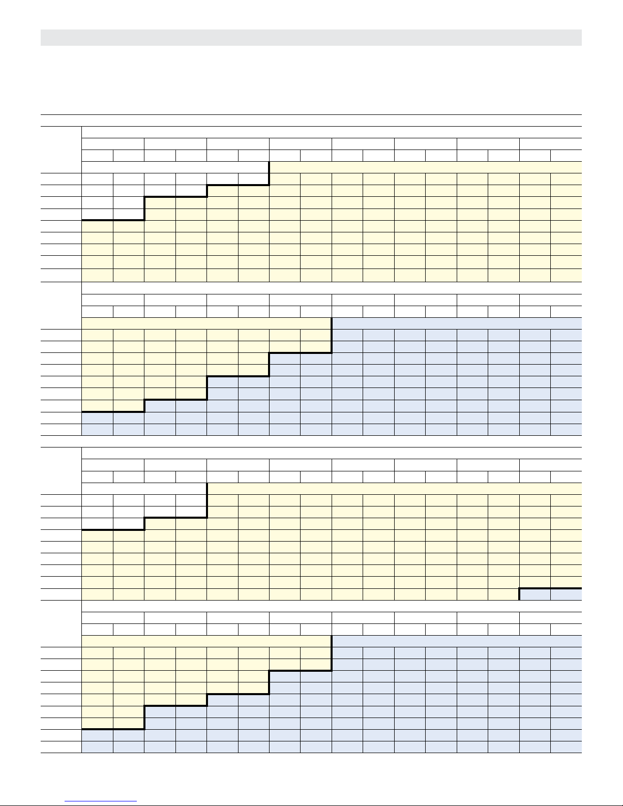
BLOWER DATA - BELT DRIVE - KCA060
BLOWER TABLE INCLUDES RESISTANCE FOR BASE UNIT ONLY WITH DRY INDOOR COIL AND AIR FILTERS IN PLACE.
FOR ALL UNITS ADD:
1 - Any factory installed options air resistance (economizer, wet coil, etc.) See page 41.
2 - Any eld installed accessories air resistance (electric heat, duct resistance, diffuser, etc.) See page 41.
See page 41 for blower motors and drives and wet coil and options/accessory air resistance data.
DOWNFLOW
Air
Volume
cfm
1600 738 0.32 785 0.36 831 0.41 878 0.45 923 0.49 969 0.53 1014 0.57 1061 0.59
1700 773 0.36 816 0.41 859 0.46 903 0.51 947 0.55 991 0.58 1036 0.62 1082 0.65
1800 803 0.42 844 0.47 886 0.52 929 0.57 972 0.61 1016 0.64 1060 0.68 1106 0.71
1900 831 0.48 872 0.54 915 0.59 957 0.63 1000 0.67 1043 0.71 1087 0.74 1131 0.78
2000 861 0.56 903 0.61 945 0.66 988 0.70 1030 0.74 1072 0.77 1115 0.81 1157 0.85
2100 893 0.63 935 0.69 978 0.73 1019 0.78 1060 0.81 1101 0.85 1143 0.89 1182 0.93
2200 927 0.71 969 0.76 1011 0.81 1052 0.85 1091 0.89 1131 0.93 1170 0.97 1206 1.02
2300 963 0.79 1004 0.84 1045 0.89 1084 0.93 1122 0.97 1159 1.02 1195 1.07 1228 1.13
2400 999 0.88 1039 0.92 1078 0.97 1115 1.02 1151 1.06 1186 1.12 1219 1.18 1250 1.24
Air
Volume
cfm
1600 1107 0.62 1151 0.66 1190 0.70 1228 0.74 1264 0.78 1298 0.82 1332 0.86 1364 0.90
1700 1128 0.68 1169 0.72 1206 0.76 1242 0.80 1277 0.84 1310 0.88 1343 0.92 1375 0.96
1800 1150 0.74 1189 0.79 1223 0.83 1257 0.87 1291 0.91 1324 0.95 1356 0.99 1388 1.03
1900 1173 0.81 1208 0.86 1240 0.91 1273 0.95 1306 0.99 1338 1.03 1369 1.07 1401 1.12
2000 1195 0.89 1228 0.94 1257 0.99 1290 1.04 1321 1.08 1353 1.12 1384 1.16 1416 1.20
2100 1217 0.98 1247 1.04 1275 1.09 1306 1.14 1338 1.18 1369 1.22 1400 1.25 1432 1.29
2200 1238 1.08 1265 1.14 1293 1.19 1324 1.24 1355 1.28 1387 1.31 1418 1.35 1450 1.39
2300 1257 1.19 1284 1.25 1313 1.30 1344 1.34 1375 1.38 1406 1.41 1437 1.45 1470 1.48
2400 1278 1.30 1305 1.36 1334 1.40 1364 1.44 1395 1.48 1427 1.51 1458 1.55 1492 1.58
HORIZONTAL
Air
Volume
cfm
1600 752 0.30 798 0.35 844 0.40 889 0.45 933 0.49 975 0.53 1018 0.57 1062 0.60
1700 785 0.35 827 0.40 871 0.46 914 0.51 957 0.55 999 0.59 1042 0.63 1085 0.66
1800 813 0.42 855 0.47 898 0.52 940 0.57 983 0.62 1025 0.66 1067 0.69 111 0 0.72
1900 841 0.49 883 0.54 926 0.60 969 0.65 1011 0.69 1052 0.72 1094 0.76 1136 0.79
2000 871 0.56 914 0.62 957 0.67 1000 0.72 1040 0.76 1081 0.79 1122 0.83 1162 0.87
2100 903 0.64 946 0.70 990 0.75 1031 0.79 1071 0.83 1110 0.87 1150 0.91 1189 0.96
2200 937 0.73 981 0.78 1023 0.83 1063 0.87 1102 0.91 1140 0.96 1178 1.01 1215 1.07
2300 973 0.81 1015 0.86 1056 0.91 1095 0.96 1132 1.01 1170 1.06 1206 1.12 1242 1.19
2400 1010 0.91 1051 0.96 1090 1.01 1127 1.06 1164 1.11 1200 1.18 1235 1.24 1269 1.31
Air
Volume
cfm
1600 1107 0.63 1149 0.67 1187 0.71 1223 0.75 1258 0.79 1291 0.83 1323 0.87 1354 0.91
1700 1129 0.69 1169 0.73 1204 0.78 1240 0.82 1274 0.86 1306 0.90 1338 0.95 1369 0.99
1800 1152 0.76 1190 0.80 1223 0.85 1258 0.90 1291 0.94 1323 0.99 1354 1.03 1385 1.07
1900 1176 0.83 1212 0.89 1243 0.94 1277 0.99 1309 1.03 1341 1.08 1372 1.12 1402 1.16
2000 1201 0.92 1234 0.98 1264 1.04 1296 1.09 1329 1.13 1360 1.18 1391 1.22 1422 1.26
2100 1225 1.02 1256 1.08 1285 1.14 1318 1.19 1349 1.24 1381 1.28 1412 1.32 1442 1.36
2200 1249 1.13 1279 1.19 1308 1.25 1340 1.30 1372 1.34 1403 1.38 1434 1.42 1465 1.46
2300 1273 1.25 1303 1.31 1332 1.36 1364 1.41 1396 1.45 1427 1.49 1458 1.53 1490 1.57
2400 1300 1.37 1329 1.43 1359 1.47 1390 1.52 1422 1.56 1453 1.60 1484 1.64 1516 1.67
0.10 0.20 0.30 0.40 0.50 0.60 0.70 0.80
RPM BHP RPM BHP RPM BHP RPM BHP RPM BHP RPM BHP RPM BHP RPM BHP
Field Furnished Drive Kit A03
0.90 1.00 1.10 1.20 1.30 1.40 1.50 1.60
RPM BHP RPM BHP RPM BHP RPM BHP RPM BHP RPM BHP RPM BHP RPM BHP
Drive Kit A03 Drive Kit A07
0.10 0.20 0.30 0.40 0.50 0.60 0.70 0.80
RPM BHP RPM BHP RPM BHP RPM BHP RPM
Field Furnished Drive
0.90 1.00 1.10 1.20 1.30 1.40 1.50 1.60
RPM BHP RPM BHP RPM BHP RPM BHP RPM BHP RPM BHP RPM BHP RPM BHP
Drive Kit A03 Drive Kit A07
External Static - in. w.g.
External Static - in. w.g.
External Static - in. w.g.
BHP RPM BHP RPM BHP RPM BHP
Kit A03
External Static - in. w.g.
Page 35
Page 36

BLOWER DATA - BELT DRIVE - KCB060
BLOWER TABLE INCLUDES RESISTANCE FOR BASE UNIT ONLY WITH DRY INDOOR COIL AND AIR FILTERS IN PLACE.
FOR ALL UNITS ADD:
1 - Any factory installed options air resistance (economizer, wet coil, etc.) See page 41.
2 - Any eld installed accessories air resistance (electric heat, duct resistance, diffuser, etc.) See page 41.
See page 41 for blower motors and drives and wet coil and options/accessory air resistance data.
DOWNFLOW
Air
Volume
cfm
1600 665 0.30 716 0.34 768 0.38 819 0.41 879 0.44 937 0.46 985 0.49 1022 0.52
1700 723 0.31 768 0.35 814 0.39 860 0.43 910 0.47 959 0.50 1001 0.54 1037 0.58
1800 779 0.32 818 0.37 857 0.41 897 0.46 939 0.50 980 0.55 1018 0.59 1054 0.64
1900 826 0.36 859 0.41 894 0.45 928 0.50 964 0.56 1000 0.61 1036 0.66 1072 0.70
2000 857 0.42 889 0.47 920 0.52 952 0.57 986 0.62 1020 0.68 1055 0.73 1091 0.77
2100 878 0.49 909 0.54 940 0.59 973 0.64 1006 0.70 1041 0.75 1076 0.80 111 2 0.85
2200 897 0.55 929 0.61 961 0.66 994 0.72 1028 0.78 1063 0.83 1099 0.89 1134 0.93
2300 918 0.62 950 0.68 983 0.74 1017 0.80 1052 0.86 1087 0.92 1122 0.97 1157 1.02
2400 941 0.70 974 0.77 1008 0.83 1042 0.90 1077 0.96 1111 1.01 1146 1.06 1181 1.11
Air
Volume
cfm
1600 1059 0.57 1098 0.61 1138 0.65 1177 0.68 1218 0.71 1257 0.75 1290 0.79 1319 0.83
1700 1074 0.62 1113 0.66 1152 0.70 1190 0.74 1231 0.77 1268 0.80 1299 0.84 1328 0.89
1800 1091 0.68 1129 0.72 1167 0.76 1205 0.80 1244 0.83 1280 0.87 1310 0.91 1338 0.95
1900 1109 0.75 1146 0.79 1183 0.82 1221 0.86 1260 0.90 1294 0.94 1323 0.98 1349 1.02
2000 1128 0.82 1164 0.86 1201 0.89 1239 0.93 1276 0.97 1310 1.01 1336 1.06 1362 1.10
2100 1148 0.89 1185 0.93 1221 0.97 1258 1.01 1294 1.05 1325 1.09 1351 1.14 1376 1.19
2200 1170 0.97 1206 1.01 1242 1.05 1277 1.09 1311 1.14 1341 1.18 1365 1.23 1390 1.28
2300 1193 1.06 1228 1.09 1262 1.14 1295 1.19 1327 1.24 1355 1.29 1380 1.33 1406 1.37
2400 1216 1.15 1250 1.19 1282 1.24 1313 1.30 1343 1.36 1371 1.40 1396 1.44 1423 1.48
HORIZONTAL
Air
Volume
cfm
1600 712 0.29 758 0.32 807 0.36 855 0.39 906 0.43 955 0.46 997 0.50 1035 0.54
1700 766 0.32 808 0.36 850 0.40 892 0.44 936 0.47 978 0.51 1016 0.56 1052 0.60
1800 814 0.36 851 0.40 888 0.44 925 0.49 963 0.53 1000 0.57 1035 0.62 1071 0.66
1900 853 0.41 886 0.46 919 0.50 952 0.55 986 0.60 1021 0.64 1056 0.69 1091 0.73
2000 883 0.48 913 0.53 944 0.57 976 0.62 1009 0.67 1043 0.71 1078 0.76 111 2 0.80
2100 906 0.56 936 0.60 967 0.65 999 0.70 1033 0.75 1067 0.79 1101 0.84 1135 0.88
2200 930 0.64 960 0.68 991 0.73 1024 0.78 1058 0.83 1092 0.88 1126 0.92 1160 0.96
2300 954 0.72 985 0.77 1017 0.82 1051 0.87 1085 0.92 1119 0.96 1152 1.00 1186 1.04
2400 981 0.81 1013 0.86 1046 0.91 1079 0.96 111 3 1.00 1146 1.05 1180 1.09 1213 1.13
Air
Volume
cfm
1600 1071 0.58 1109 0.62 1147 0.66 1186 0.69 1225 0.72 1263 0.76 1299 0.80 1334 0.83
1700 1088 0.64 1126 0.68 1164 0.72 1202 0.75 1240 0.78 1276 0.82 1311 0.86 1345 0.90
1800 1107 0.70 1143 0.74 1181 0.78 1219 0.81 1256 0.85 1291 0.89 1324 0.93 1357 0.97
1900 1126 0.77 1163 0.81 1200 0.85 1237 0.88 1273 0.92 1306 0.96 1339 1.00 1371 1.04
2000 1148 0.84 1183 0.88 1220 0.92 1257 0.96 1291 1.00 1323 1.04 1354 1.08 1385 1.12
2100 1170 0.92 1206 0.96 1242 1.00 1277 1.04 1310 1.08 1340 1.13 1371 1.17 1401 1.21
2200 1195 1.00 1230 1.04 1265 1.08 1299 1.13 1330 1.18 1359 1.23 1388 1.27 1418 1.31
2300 1220 1.08 1254 1.13 1288 1.17 1320 1.23 1350 1.28 1378 1.34 1406 1.38 1435 1.42
2400 1245 1.18 1278 1.22 1311 1.28 1341 1.33 1370 1.40 1397 1.45 1425 1.50 1454 1.54
0.10 0.20 0.30 0.40 0.50 0.60 0.70 0.80
RPM BHP RPM BHP RPM BHP RPM BHP RPM BHP RPM BHP RPM BHP RPM BHP
Field Furnished Drive Kit A03
0.90 1.00 1.10 1.20 1.30 1.40 1.50 1.60
RPM BHP RPM BHP RPM BHP RPM BHP RPM BHP RPM BHP RPM BHP RPM BHP
Drive Kit A03 Drive Kit A07
0.10 0.20 0.30 0.40 0.50 0.60 0.70 0.80
RPM BHP RPM BHP RPM BHP RPM BHP RPM
Field Furnished Drive
0.90 1.00 1.10 1.20 1.30 1.40 1.50 1.60
RPM BHP RPM BHP RPM BHP RPM BHP RPM BHP RPM BHP RPM BHP RPM BHP
Drive Kit A03 Drive Kit A07
External Static - in. w.g.
External Static - in. w.g.
External Static - in. w.g.
BHP RPM BHP RPM BHP RPM BHP
Kit A03
External Static - in. w.g.
Page 36
Page 37

BLOWER DATA - BELT DRIVE - KCA072, KCB072 & 074 - DOWNFLOW
BLOWER TABLE INCLUDES RESISTANCE FOR BASE UNIT ONLY WITH DRY INDOOR COIL AND AIR FILTERS IN PLACE.
FOR ALL UNITS ADD:
1 - Any factory installed options air resistance (economizer, wet coil, etc.) See page 41.
2 - Any eld installed accessories air resistance (electric heat, duct resistance, diffuser, etc.) See page 41.
See pagepage 41 for blower motors and drives and wet coil and options/accessory air resistance data.
External Static - in. w.g.
Air
Volume
cfm
1900 826 0.36 859 0.41 894 0.45 928 0.50 964 0.56 1000 0.61 1036 0.66 1072 0.70
2000 857 0.42 889 0.47 920 0.52 952 0.57 986 0.62 1020 0.68 1055 0.73 1091 0.77
2100 878 0.49 909 0.54 940 0.59 973 0.64 1006 0.70 1041 0.75 1076 0.80 111 2 0.85
2200 897 0.55 929 0.61 961 0.66 994 0.72 1028 0.78 1063 0.83 1099 0.89 1134 0.93
2300 918 0.62 950 0.68 983 0.74 1017 0.80 1052 0.86 1087 0.92 1122 0.97 1157 1.02
2400 941 0.70 974 0.77 1008 0.83 1042 0.90 1077 0.96 1111 1.01 1146 1.06 1181 1.11
2500 966 0.79 1000 0.86 1034 0.93 1068 1.00 1103 1.06 1137 1.11 1171 1.16 1205 1.20
2600 994 0.90 1028 0.97 1062 1.04 1096 1.10 1130 1.16 1164 1.21 1197 1.26 1231 1.30
2700 1023 1.01 1057 1.08 1091 1.15 1125 1.22 1159 1.27 1192 1.32 1225 1.37 1258 1.41
2800 1053 1.13 1088 1.21 1122 1.27 1155 1.33 1188 1.39 1221 1.43 1253 1.48 1286 1.53
2900 1085 1.26 1119 1.33 1153 1.40 1186 1.45 1218 1.51 1250 1.55 1281 1.61 1313 1.66
Air
Volume
cfm
1900 1109 0.75 1146 0.79 1183 0.82 1221 0.86 1260 0.90 1294 0.94 1323 0.98 1349 1.02
2000 1128 0.82 1164 0.86 1201 0.89 1239 0.93 1276 0.97 1310 1.01 1336 1.06 1362 1.10
2100 1148 0.89 1185 0.93 1221 0.97 1258 1.01 1294 1.05 1325 1.09 1351 1.14 1376 1.19
2200 1170 0.97 1206 1.01 1242 1.05 1277 1.09 1311 1.14 1341 1.18 1365 1.23 1390 1.28
2300 1193 1.06 1228 1.09 1262 1.14 1295 1.19 1327 1.24 1355 1.29 1380 1.33 1406 1.37
2400 1216 1.15 1250 1.19 1282 1.24 1313 1.30 1343 1.36 1371 1.40 1396 1.44 1423 1.48
2500 1240 1.24 1273 1.29 1302 1.36 1331 1.42 1360 1.48 1388 1.52 1414 1.55 1441 1.58
2600 1265 1.34 1296 1.40 1324 1.47 1352 1.54 1381 1.60 1408 1.64 1434 1.67 1460 1.70
2700 1291 1.46 1321 1.52 1347 1.60
2800 1317 1.58 1346 1.66 1372 1.74 1399 1.80 1426 1.85 1451 1.89 1477 1.92 1503 1.95
2900 1343 1.72 1371 1.80 1397 1.88 1424 1.95 1450 1.99 1475 2.02 1500 2.05 1526 2.08
0.10 0.20 0.30 0.40 0.50 0.60 0.70 0.80
RPM BHP RPM BHP RPM BHP RPM BHP RPM BHP RPM BHP RPM BHP RPM BHP
Field Furnished Drive Kit A04
External Static - in. w.g.
0.90 1.00 1.10 1.20 1.30 1.40 1.50 1.60
RPM BHP RPM BHP RPM BHP RPM BHP RPM BHP RPM BHP RPM BHP RPM BHP
Drive Kit A04 Kit A08
1374 1.67 1403 1.72 1429 1.76 1455 1.79 1481 1.82
Page 37
Page 38

BLOWER DATA - BELT DRIVE - KCA072, KCB072 & 074 - HORIZONTAL
BLOWER TABLE INCLUDES RESISTANCE FOR BASE UNIT ONLY WITH DRY INDOOR COIL AND AIR FILTERS IN PLACE.
FOR ALL UNITS ADD:
1 - Any factory installed options air resistance (economizer, wet coil, etc.) See page 41.
2 - Any eld installed accessories air resistance (electric heat, duct resistance, diffuser, etc.) See page 41.
See page 41 for blower motors and drives and wet coil and options/accessory air resistance data.
External Static - in. w.g.
Air
Volume
cfm
1900 853 0.41 886 0.46 919 0.50 952 0.55 986 0.60 1021 0.64 1056 0.69 1091 0.73
2000 883 0.48 913 0.53 944 0.57 976 0.62 1009 0.67 1043 0.71 1078 0.76 111 2 0.80
2100 906 0.56 936 0.60 967 0.65 999 0.70 1033 0.75 1067 0.79 1101 0.84 1135 0.88
2200 930 0.64 960 0.68 991 0.73 1024 0.78 1058 0.83 1092 0.88 1126 0.92 1160 0.96
2300 954 0.72 985 0.77 1017 0.82 1051 0.87 1085 0.92 1119 0.96 1152 1.00 1186 1.04
2400 981 0.81 1013 0.86 1046 0.91 1079 0.96 111 3 1.00 1146 1.05 1180 1.09 1213 1.13
2500 1010 0.91 1042 0.96 1075 1.00 1109 1.05 1142 1.09 1175 1.14 1207 1.18 1239 1.23
2600 1040 1.01 1073 1.05 1106 1.10 1139 1.14 1171 1.19 1203 1.23 1235 1.28 1266 1.33
2700 1072 1.10 1104 1.15 1137 1.20 1169 1.24 1201 1.29 1232 1.34 1263 1.40 1293 1.46
2800 1105 1.21 1137 1.25 1168 1.30 1200 1.35 1231 1.40 1261 1.46 1291 1.52 1321 1.59
2900 1138 1.32 1169 1.37 1200 1.42 1231 1.47 1261 1.53 1291 1.60 1321 1.66 1350 1.73
Air
Volume
cfm
1900 1126 0.77 1163 0.81 1200 0.85 1237 0.88 1273 0.92 1306 0.96 1339 1.00 1371 1.04
2000 1148 0.84 1183 0.88 1220 0.92 1257 0.96 1291 1.00 1323 1.04 1354 1.08 1385 1.12
2100 1170 0.92 1206 0.96 1242 1.00 1277 1.04 1310 1.08 1340 1.13 1371 1.17 1401 1.21
2200 1195 1.00 1230 1.04 1265 1.08 1299 1.13 1330 1.18 1359 1.23 1388 1.27 1418 1.31
2300 1220 1.08 1254 1.13 1288 1.17 1320 1.23 1350 1.28 1378 1.34 1406 1.38 1435 1.42
2400 1245 1.18 1278 1.22 1311 1.28 1341 1.33 1370 1.40 1397 1.45 1425 1.50 1454 1.54
2500 1271 1.28 1303 1.33 1334 1.39 1363 1.45 1391 1.52 1418 1.57 1446 1.62 1474 1.66
2600 1297 1.39 1328 1.45 1357 1.52 1385 1.58 1412 1.64 1439 1.70 1467 1.74 1495 1.78
2700 1323 1.52 1353 1.58 1382 1.65
2800 1351 1.65 1380 1.72 1407 1.78 1434 1.85 1460 1.90 1486 1.95 1513 1.99 1541 2.02
2900 1379 1.79 1407 1.86 1434 1.92 1460 1.98 1485 2.04 151
0.10 0.20 0.30 0.40 0.50 0.60 0.70 0.80
RPM BHP RPM BHP RPM BHP RPM BHP RPM BHP RPM BHP RPM BHP RPM BHP
Field Furnished Drive Kit A04
External Static - in. w.g.
0.90 1.00 1.10 1.20 1.30 1.40 1.50 1.60
RPM BHP RPM BHP RPM BHP RPM BHP RPM BHP RPM BHP RPM BHP RPM BHP
Drive Kit A04 Kit A08
1409 1.72 1435 1.77 1462 1.82 1490 1.86 1517 1.90
1 2.08 1538 2.12 1565 2.15
Page 38
Page 39
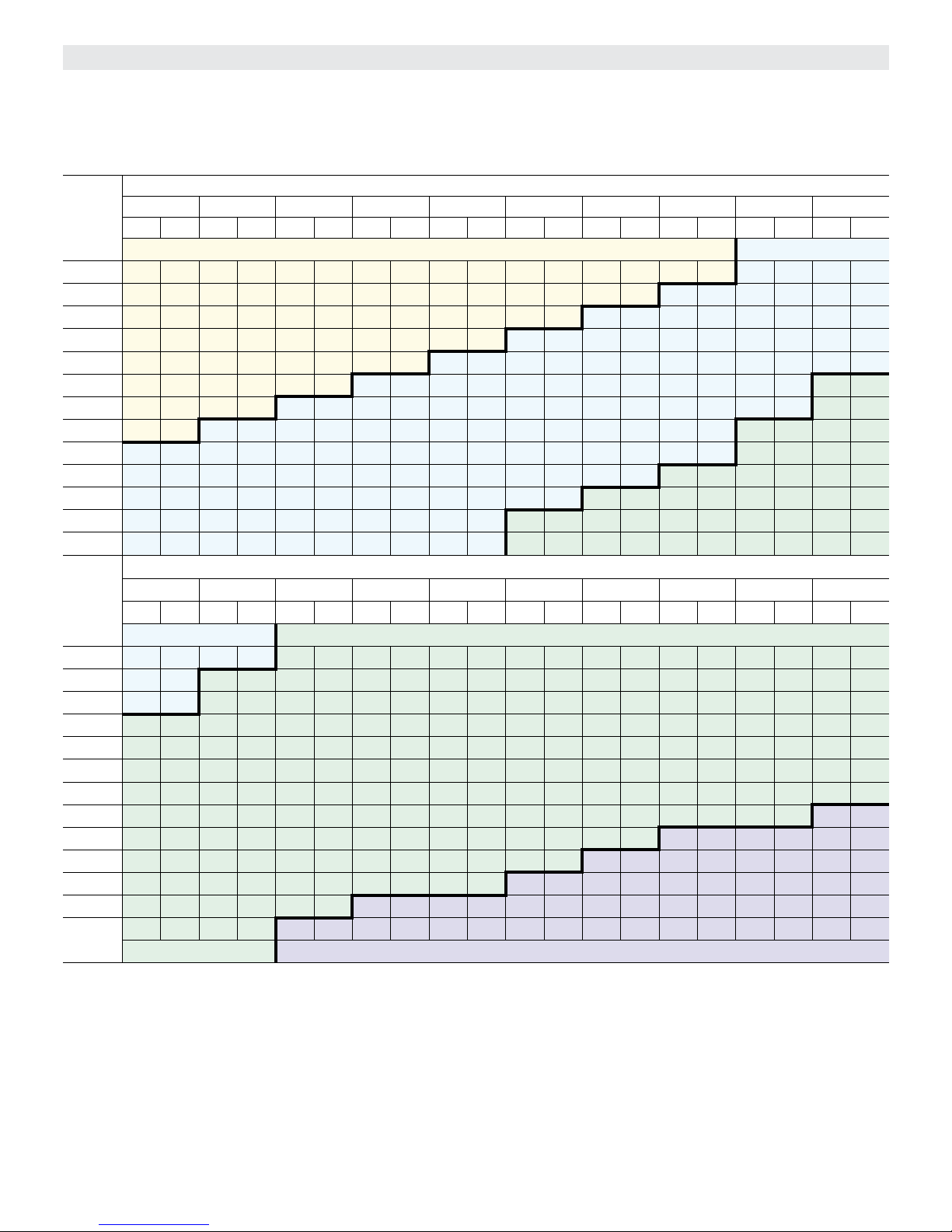
BLOWER DATA - BELT DRIVE - KCA090 - DOWNFLOW
BLOWER TABLE INCLUDES RESISTANCE FOR BASE UNIT ONLY WITH DRY INDOOR COIL AND AIR FILTERS IN PLACE.
FOR ALL UNITS ADD:
1 - Any factory installed options air resistance (economizer, wet coil, etc.) See page 41.
2 - Any eld installed accessories air resistance (electric heat, duct resistance, diffuser, etc.) See page 41.
See page 41 for blower motors and drives and wet coil and options/accessory air resistance data.
External Static - in. w.g.
Air
Volume
cfm
2400 553 0.65 585 0.71 617 0.78 649 0.85 680 0.91 711 0.98 740 1.04 769 1.10 796 1.15 821 1.21
2500 570 0.71 602 0.78 633 0.84 665 0.91 695 0.97 725 1.04 753 1.10 781 1.16 807 1.22 832 1.27
2600 588 0.77 619 0.84 650 0.91 680 0.97 710 1.04 739 1.10 767 1.16 793 1.22 818 1.28 842 1.33
2700 607 0.84 637 0.91 667 0.97 697 1.04 726 1.11 753 1.17 780 1.23 806 1.29 830 1.35 854 1.40
2800 626 0.91 655 0.97 684 1.04 713 1.11 741 1.18 768 1.24 794 1.30 819 1.36 842 1.42 866 1.47
2900 646 0.98 674 1.05 702 1.11 730 1.18 757 1.25 783 1.32 808 1.38 832 1.44 855 1.49 878 1.54
3000 666 1.06 693 1.12 721 1.19 747 1.26 774 1.33 799 1.40 823 1.46 846 1.52 868 1.57 891 1.62
3100 686 1.14 713 1.21 739 1.28 765 1.35 790 1.41 814 1.48 838 1.55 860 1.61 882 1.66 904 1.70
3200 707 1.22 732 1.29 758 1.36 783 1.43 807 1.50 830 1.57 853 1.64 874 1.70 896 1.75 918 1.79
3300 727 1.31 752 1.38 776 1.46 800 1.53 823 1.60 846 1.67 868 1.73 889 1.79 9 11 1.84 932 1.89
3400 747 1.41 771 1.48 794 1.55 817 1.63 840 1.70 862 1.77 883 1.83 904 1.89 925 1.94 947 1.98
3500 767 1.51 790 1.58 812 1.66 835 1.73 856 1.80 878 1.87 899 1.93 920 1.99 940 2.04 961 2.08
3600 786 1.61 808 1.69 830 1.77 852 1.84 873 1.91 894 1.98 915 2.04 935 2.09 955 2.14 975 2.19
Air
Volume
cfm
2400 846 1.25 870 1.29 895 1.33 920 1.37 947 1.41 972 1.45 996 1.50 1018 1.55 1039 1.61 1059 1.67
2500 856 1.31 880 1.35 905 1.39 930 1.43 956 1.47 980 1.52 1003 1.57 1024 1.63 1044 1.69 1064 1.76
2600 866 1.38 891 1.42 915 1.46 940 1.50 965 1.54 988 1.59 1010 1.65 1031 1.71 1050 1.78 1069 1.84
2700 878 1.44 902 1.48 926 1.52 950 1.57 974 1.61 997 1.67 1018 1.73 1037 1.80 1056 1.87 1075 1.93
2800 889 1.51 913 1.55 937 1.59 961 1.64 984 1.69 1006 1.75 1026 1.82 1044 1.89 1063 1.96 1081 2.03
2900 902 1.58 925 1.63 949 1.67 972 1.72 994 1.78 1015 1.84 1034 1.91 1052 1.99 1069 2.06 1087 2.13
3000 914 1.66 938 1.71 961 1.75 983 1.81 1004 1.87 1024 1.94 1042 2.01 1059 2.09 1076 2.16 1093 2.23
3100 927 1.75 950 1.79 972 1.84 994 1.90 1014 1.96 1033 2.04 1050 2.11 1067 2.19 1083 2.27 1100 2.34
3200 941 1.84 963 1.88 984 1.94 1005 2.00 1024 2.07 1042 2.14 1059 2.23 1075 2.31 1091 2.39 1107 2.46
3300 954 1.93 976 1.98 996 2.04 1016 2.10 1035 2.18 1052 2.26 1067 2.35 1083 2.43 1098 2.51 1114 2.59
3400 968 2.03 989 2.08 1008 2.14 1027 2.22 1045 2.30 1061 2.38 1076 2.47 1091 2.57 1106 2.65 1121 2.73
3500 982 2.13 1001 2.19 1020 2.26 1038 2.33 1054 2.42 1070 2.51 1084 2.61 1099 2.71 1113 2.79 1128 2.87
3600 995 2.24 1014 2.30 1031 2.38 1048 2.46 1064 2.55 1079 2.65 1093 2.76 1107 2.86 1121 2.95 1136 3.03
0.10 0.20 0.30 0.40 0.50 0.60 0.70 0.80 0.90 1.00
RPM BHP RPM BHP RPM BHP RPM BHP RPM BHP RPM BHP RPM BHP RPM BHP RPM BHP RPM BHP
Drive Kit AA01 Drive Kit AA02
External Static - in. w.g.
0.90 1.00 1.30 1.40 1.50 1.60 1.70 1.80 1.90 2.00
RPM BHP RPM BHP RPM BHP RPM BHP RPM BHP RPM BHP RPM BHP RPM BHP RPM BHP RPM BHP
Drive Kit AA02 Drive Kit AA03
Drive Kit - AA03 Drive Kit - AA04
Page 39
Page 40

BLOWER DATA - BELT DRIVE - KCA090 - HORIZONTAL
BLOWER TABLE INCLUDES RESISTANCE FOR BASE UNIT ONLY WITH DRY INDOOR COIL AND AIR FILTERS IN PLACE.
FOR ALL UNITS ADD:
1 - Any factory installed options air resistance (economizer, wet coil, etc.) See page 41.
2 - Any eld installed accessories air resistance (electric heat, duct resistance, diffuser, etc.) See page 41.
See page 41 for blower motors and drives and wet coil and options/accessory air resistance data.
Air
Volume
cfm
2400 596 0.79 626 0.82 657 0.85 688 0.89 718 0.92 749 0.96 778 1.01 806 1.06 833 1.11 858 1.16
2500 616 0.85 645 0.88 676 0.91 706 0.95 736 0.99 765 1.03 794 1.08 821 1.13 847 1.18 871 1.23
2600 636 0.91 665 0.94 695 0.98 724 1.02 754 1.06 782 1.10 809 1.15 836 1.20 861 1.25 885 1.30
2700 657 0.97 685 1.01 714 1.04 743 1.08 771 1.13 799 1.17 826 1.22 851 1.27 875 1.32 899 1.37
2800 677 1.03 706 1.07 734 1.11 762 1.16 790 1.20 816 1.25 842 1.30 867 1.35 890 1.40 913 1.45
2900 698 1.10 726 1.14 754 1.19 781 1.23 808 1.28 834 1.33 859 1.38 883 1.43 906 1.48 928 1.54
3000 720 1.17 747 1.22 774 1.26 801 1.31 826 1.36 851 1.41 876 1.46 899 1.52 921 1.57 943 1.63
3100 741 1.25 768 1.30 794 1.35 820 1.40 845 1.45 869 1.50 893 1.56 915 1.61 937 1.67 959 1.73
3200 763 1.34 789 1.39 815 1.44 840 1.49 864 1.54 888 1.60 910 1.66 932 1.72 954 1.78 975 1.84
3300 785 1.43 8 11 1.48 836 1.53 860 1.59 883 1.65 906 1.71 928 1.77 950 1.83 970 1.90 991 1.96
3400 807 1.53 832 1.58 856 1.64 880 1.70 903 1.76 925 1.82 946 1.88 967 1.95 987 2.02 1007 2.09
3500 830 1.63 854 1.69 877 1.75 900 1.81 922 1.88 944 1.94 964 2.01 985 2.08 1004 2.15 1024 2.23
3600 852 1.74 876 1.81 898 1.87 921 1.94 942 2.01 963 2.07 983 2.15 1002 2.22 1022 2.29 1041 2.37
Air
Volume
cfm
2400 883 1.21 907 1.25 931 1.30 955 1.35 979 1.40 1003 1.45 1027 1.51 1050 1.57 1072 1.63 1094 1.69
2500 895 1.28 919 1.32 942 1.37 966 1.42 990 1.48 1013 1.53 1036 1.59 1059 1.65 1081 1.71 1102 1.78
2600 908 1.35 931 1.40 955 1.45 978 1.50 1001 1.56 1024 1.62 1046 1.68 1068 1.74 1089 1.80 1110 1.87
2700 922 1.43 945 1.48 967 1.53 990 1.59 1013 1.65 1035 1.71 1056 1.77 1078 1.84 1099 1.90 1119 1.96
2800 936 1.51 958 1.56 980 1.62 1003 1.68 1025 1.74 1046 1.80 1067 1.87 1088 1.93 1109 2.00 1129 2.06
2900 950 1.60 972 1.66 994 1.72 1016 1.78 1037 1.84 1058 1.91 1079 1.97 1099 2.04 111 9 2.11 1139 2.17
3000 965 1.69 986 1.76 1008 1.82 1029 1.88 1050 1.95 1070 2.02 1091 2.08 1110 2.15 1130 2.22 1149 2.28
3100 980 1.80 1001 1.86 1022 1.93 1043 2.00 1063 2.07 1083 2.13 1103 2.20 1122 2.27 1141 2.33 1160 2.40
3200 995 1.91 1016 1.98 1036 2.05 1057 2.12 1077 2.19 1096 2.26 1116 2.33 1134 2.39 1153 2.46 1171 2.52
3300 1011 2.03 1031 2.11 1051 2.18 1071 2.25 1091 2.32 1110 2.39 1129 2.45 1147 2.52 1165 2.59 1183 2.65
3400 1027 2.16 1047 2.24 1067 2.31 1086 2.38 1105 2.45 1124 2.52 1142 2.59 1160 2.66 1178 2.72 1196 2.78
3500 1043 2.30 1063 2.38 1082 2.45 1101 2.52 1120 2.59 1138 2.66 1156 2.73 1174 2.80 1191 2.86 1208 2.92
3600 1060 2.45 1079 2.52 1098 2.60 1117 2.67 1135 2.74 1153 2.81 1170 2.87 1188 2.94 1205 3.00 1222 3.06
0.10 0.20 0.30 0.40 0.50 0.60 0.70 0.80 0.90 1.00
RPM BHP RPM BHP RPM BHP RPM BHP RPM BHP RPM BHP RPM BHP RPM BHP RPM BHP RPM BHP
Drive Kit AA01 Drive Kit AA02
0.90 1.00 1.30 1.40 1.50 1.60 1.70 1.80 1.90 2.00
RPM BHP RPM BHP RPM BHP RPM BHP RPM BHP RPM BHP RPM BHP RPM BHP RPM BHP RPM BHP
External Static - in. w.g.
External Static - in. w.g.
Drive Kit AA03
Drive Kit AA04
Page 40
Page 41
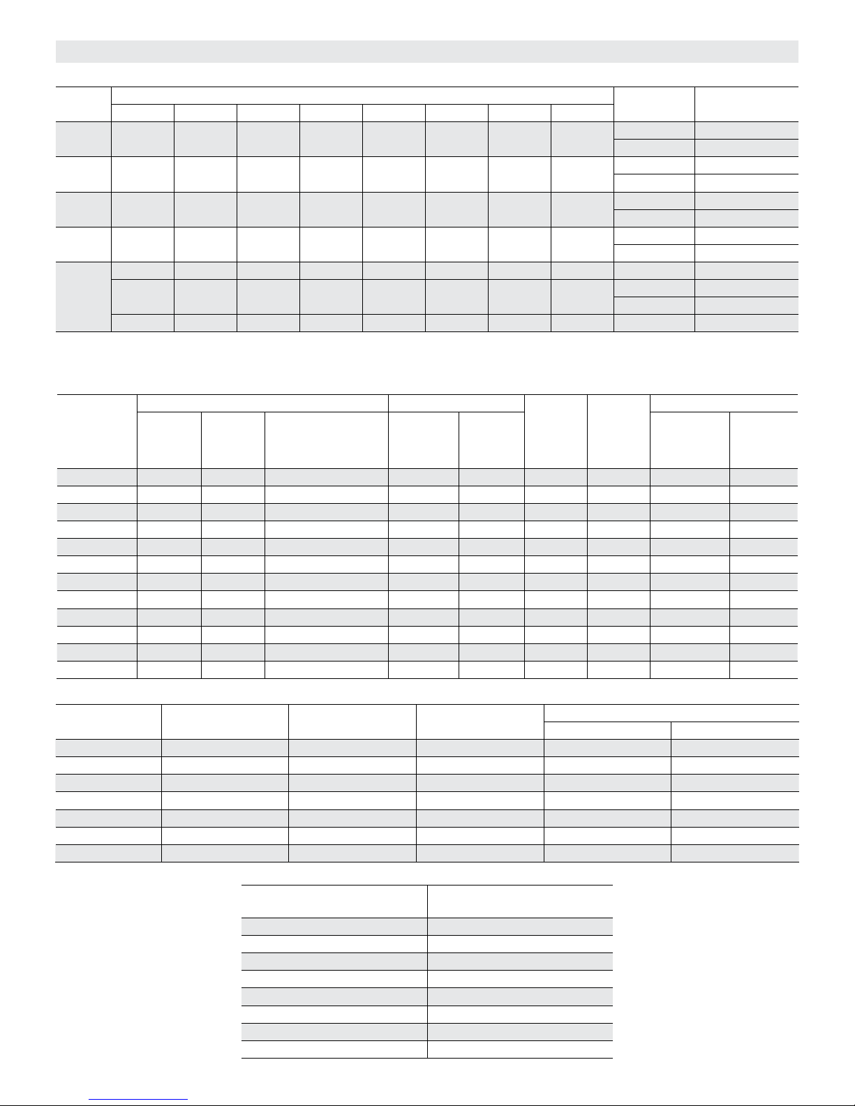
BLOWER DATA
BELT DRIVE KIT SPECIFICATIONS
Model
No.
Nominal Maximum Nominal Maximum Nominal Maximum Nominal Maximum
036 0.75 0.86 1 1.15 1.5 1.7 2 2.3
048 0.75 0.86 1 1.15 1.5 1.7 2 2.3
060 0.75 0.86 1 1.15 1.5 1.7 2 2.3
072
074
- - - - - - 1 1.15 - - - - - - 2 2.3
- - - - - - 1 1.15 - - - - - - - - - - - - AA01 522 - 784 rpm
090
- - - - - - 2 2.3 - - - - - - - - - - - -
- - - - - - 3 3.45 - - - - - - - - - - - - AA04 921 - 1228 rpm
NOTE - Using total air volume and system static pressure requirements determine from blower performance tables rpm and motor hp required. Maximum usable hp of
motors furnished are shown. In Canada, nominal motor hp is also maximum usable motor hp. If motors of comparable hp are used, be sure to keep within the service
factor limitations outlined on the motor nameplate.
OPTIONS / ACCESSORIES AIR RESISTANCE FOR 024-074 MODELS - in. w.g.
Air Volume
cfm
036-048 KCA/
Wet Indoor Coil Gas Heat Electric
KGA060
800 0.01 0.01 0.01 0.02 0.02 0.01 0.04 0.04 0.05
1000 0.02 0.02 0.01 0.02 0.02 0.03 0.04 0.04 0.07
1200 0.03 0.04 0.02 0.02 0.02 0.06 0.04 0.04 0.07
1400 0.04 0.05 0.03 0.02 0.03 0.09 0.04 0.04 0.07
1600 0.05 0.06 0.04 0.03 0.04 0.12 0.04 0.04 0.07
1800 0.06 0.07 0.05 0.03 0.05 0.15 0.05 0.05 0.07
2000 0.08 0.09 0.06 0.04 0.06 0.18 0.05 0.05 0.08
2200 0.09 0.10 0.07 0.04 0.07 0.20 0.05 0.05 0.08
2400 0.10 0.12 0.08 0.05 0.08 0.22 0.05 0.05 0.08
2600 0.11 0.13 0.09 0.05 0.09 0.24 0.06 0.05 0.08
2800 0.13 0.15 0.10 0.06 0.10 0.26 0.06 0.05 0.08
3000 0.14 0.16 0.12 0.07 0.11 0.28 0.06 0.05 0.08
Blower Motor Choice (HP)
KCB/KGB060,
072, 074
Medium
Input
KCA/KGA072
High
Input
Heat
Drive Kit No. RPM Range
A01 673 - 1010 rpm
A05 897 - 1346 rpm
A02 745 - 1117 rpm
A06 1071 - 1429 rpm
A03 833 - 1250 rpm
A07 1212 - 1548 rpm
A04 968 - 1340 rpm
A08 1193 - 1591 rpm
AA02 632 - 875 rpm
AA03 798 - 1105 rpm
Econo-
mizer
Filters
MERV 8 MERV 13
OPTIONS / ACCESSORIES AIR RESISTANCE FOR 090 MODELS - in. w.g.
Air Volume
Wet Indoor Coil Gas Heat Economizer Filters
cfm
2400 0.08 0.03 0.05 0.05 0.08
2600 0.09 0.04 0.06 0.05 0.08
2800 0.10 0.04 0.06 0.05 0.08
3000 0.11 0.04 0.06 0.05 0.08
3200 0.12 0.04 0.06 0.06 0.09
3400 0.14 0.05 0.06 0.06 0.09
3600 0.15 0.05 0.06 0.06 0.10
POWER EXHAUST FAN PERFORMANCE
Return Air System Static
Pressure - in. w.g.
High Input MERV 8 MERV 13
Air Volume Exhausted
cfm
0.00 2000
0.05 1990
0.10 1924
0.15 1810
0.20 1664
0.25 1507
0.30 1350
0.35 1210
Page 41
Page 42

TABLE 5
DRIVE COMPONENT MANUFACTURER'S NUMBERS
DRIVE COMPONENTS
MOTOR PULLEY BLOWER PULLEY BELTS
Drive No.
A01 1VP34 X 7/8 31K6901 AK54 X 1 100244-19 A40 100245-17
A02 1VP34 X 7/8 31K6901 AK49 X 1 100244-18 A39 100245-16
A03 1VP34 X 7/8 31K6901 AK44X 1 100244-16 A39 100245-16
A04 1VP40 X 7/8 79J0301 AK49 X 1 100244-18 A41 100245-18
A05 1VP34 X 7/8 31K6901 AK41 X 1 100244-15 A38 100245-15
A06 1VP44 X 7/8 P-8-1488 AK51 X 1 18L2201 A41 100245-18
A07 1VP50 X 7/8 53J1501 AK54 X 1 100244-19 AX43 73K8201
A08 1VP44 X 7/8 P-8-1488 AK46 X 1 100244-17 A40 100245-17
AA01 1VP34 X 7/8 31K6901 AK69 X 1 37L4701 A51 13H0101
AA02* 1VP40 X 7/8 79J0301 BK80H 100788-03 A53 P-8-4951
AA03 1VP40 X 7/8 79J0301 AK59 X 1 31K6801 A50 100245-29
AA04 1VP44 X 7/8 P-8-1488 AK59 X 1 31K6801 A51 13H0101
*Split bushing supplier no.: H1; OEM no. 10073-04
Browning No. OEM Part No. Browning No. OEM Part No. Browning No. OEM Part No.
Cooling Start-Up
A-Operation
1- Initiate first and second stage cooling demands
according to instructions provided with thermostat.
See table 6 for operation.
Note - KG/KC 074 units are equipped with two-stage
compressors.
TABLE 6
COOLING OPERATION
T'Stat
Demand
024-072 No Economizer or Outdoor Air Unsuitable
Y1 Compressor Condenser Fan
Y2 Compressor Condenser Fan
024-072 Unit Equipped With An Economizer
Y1 Economizer na
Y2 Economizer + Compressor Condenser Fan
074 No Economizer or Outdoor Air Unsuitable
Y1 Compressor Low Speed* Condenser Fan
Y2 Compressor High Speed** Condenser Fan
074 Unit Equipped With An Economizer
Y1 Economizer na
Y2
Economizer + Compressor
Low Speed*
*67% of full capacity **100% of full capacity
Energized
Condenser Fan
2- Units contain one refrigerant circuit or stage.
3- Unit is charged with R-410A refrigerant. See unit
rating plate for correct amount of charge.
4- Refer to Refrigerant Charge and Check section for
proper method to check refrigerant charge.
B-Three Phase Scroll Compressor Voltage Phasing
Three phase scroll compressors must be phased
sequentially to ensure correct compressor and blower
rotation and operation. Compressor and blower are wired
in phase at the factory. Power wires are color-coded as
follows: line 1-red, line 2-yellow, line 3-blue.
1- Observe suction and discharge pressures and
blower rotation on unit start-up.
2- Suction pressure must drop, discharge pressure
must rise and blower rotation must match rotation
marking.
If pressure differential is not observed or blower rotation is
not correct:
3- Disconnect all remote electrical power supplies.
4- Reverse any two field-installed wires connected to
the line side of K1 contactor. Do not reverse wires at
blower contactor.
5- Make sure the connections are tight.
Discharge and suction pressures should operate at
their normal start‐up ranges.
KG/KC 024, 030, 036, 048, 060, 072, 074, 090
Page 42
Page 43

C-Refrigerant Charge and Check - Fin/Tube Coil
KGA/KCA 036 to 060
WARNING-Do not exceed nameplate charge under
any condition.
This unit is factory charged and should require no further
adjustment. If the system requires charge, reclaim the
charge, evacuate the system and add required
nameplate charge.
NOTE - System charging is not recommended below
60°F (15°C). In temperatures below 60°F (15°C) , the
charge must be weighed into the system.
If weighing facilities are not available, or to check the
charge, use the following procedure:
1- Attach gauge manifolds and operate unit in cooling
mode until system stabilizes (approximately five
minutes). Make sure outdoor air dampers are closed.
2- Use a thermometer to accurately measure the
outdoor ambient temperature.
3- Apply the outdoor temperature to tables 7 through 12
to determine normal operating pressures.
4- Compare the normal operating pressures to the
pressures obtained from the gauges. Minor
variations in these pressures may be expected due to
differences in installations. Significant differences
could mean that the system is not properly charged
or that a problem exists with some component in the
system. Correct any system problems before
proceeding.
5- If discharge pressure is high, remove refrigerant from
the system. If discharge pressure is low, add
refrigerant to the system.
Add or remove charge in increments.
Allow the system to stabilize each time
refrigerant is added or removed.
6- Use the following approach method along with the
normal operating pressures to confirm readings.
TABLE 7
KGA 036S -3 & LOWER; KCA 036S -2 & LOWER
NORMAL OPERATING PRESSURES
Outdoor Coil
Entering Air Temp
655 F 269 146
755 F 311 148
855 F 357 150
955 F 407 152
1055 F 466 155
1155 F 532 157
Discharge
10 psig
+
Suction + 5
psig
TABLE 8
KGA 036S -4 & HIGHER; KCA 036S -3 & HIGHER
NORMAL OPERATING PRESSURES
Outdoor Coil
Entering Air Temp
65° F 275 137
75° F 312 139
85° F 353 142
95° F 399 146
105° F 450 149
115° F 506 150
Discharge
10 psig
+
Suction + 5
psig
TABLE 9
KGA 048S -3 & LOWER; KCA 048S -2 & LOWER
NORMAL OPERATING PRESSURES
Outdoor Coil
Entering Air Temp
65° F 280 142
75° F 321 144
85° F 365 147
95° F 414 149
105° F 467 151
115° F 526 153
Discharge
10 psig
+
Suction + 5
psig
TABLE 10
KGA 048 -4 & HIGHER; KCA 048S -3 & HIGHER
NORMAL OPERATING PRESSURES
Outdoor Coil
Entering Air Temp
65° F 279 132
75° F 319 136
85° F 360 140
95° F 404 144
105° F 454 147
115° F 506 148
Discharge
10 psig
+
Suction + 5
psig
TABLE 11
KGA 060S -4 & LOWER; KCA 060S -3 & LOWER
NORMAL OPERATING PRESSURES
Outdoor Coil
Entering Air Temp
65° F 265 136
75° F 302 137
85° F 344 139
95° F 391 142
105° F 442 146
115° F 499 148
Discharge
10 psig
+
Suction + 5
psig
Page 43
507348-04 12/2015
Page 44
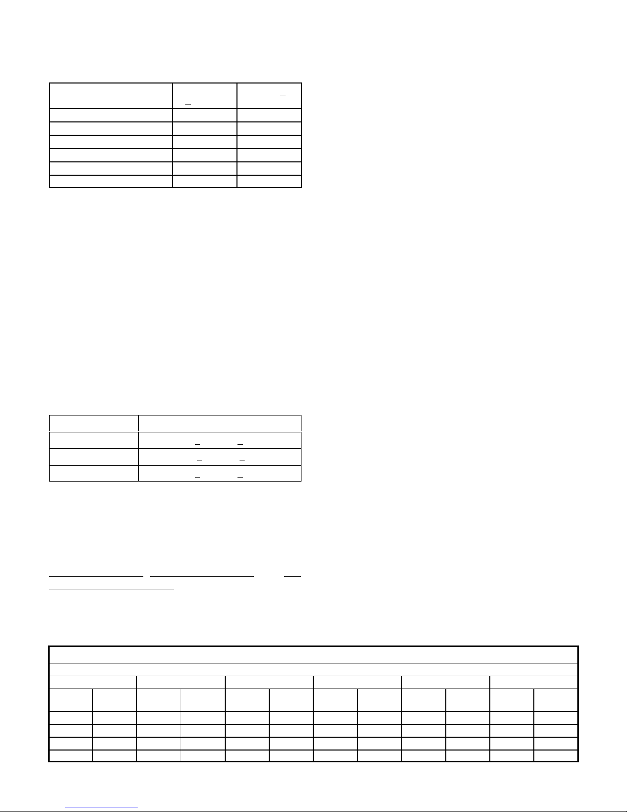
TABLE 12
KGA 060S -5 & HIGHER; KCA 060S -4 & HIGHER
If weighing facilities are not available, or to check the
charge, use the following procedure:
NORMAL OPERATING PRESSURES
Outdoor Coil
Entering Air Temp
65 279 130
75 317 135
85 359 139
95 404 143
105 454 143
115 508 143
Discharge
10 psig
+
Suction + 5
psig
D-Charge Verification-Approach Method--Fin/Tube Coils
KGA/KCA 036-060 Units
1- Using the same thermometer, compare liquid
temperature to outdoor ambient temperature.
Approach Temperature = Liquid temperature minus
ambient temperature.
2- Approach temperature should match values in table
IMPORTANT - Charge unit in standard cooling mode.
1- Make sure outdoor coil is clean. Attach gauge
manifolds and operate unit at full CFM in cooling mode
with economizer disabled until system stabilizes
(approximately five minutes). Make sure all outdoor air
dampers are closed.
2- Compare the normal operating pressures (see table
14 through 21) to the pressures obtained from the
gauges. Check unit components if there are
significant differences.
3- Measure the outdoor ambient temperature and the
suction pressure. Refer to the appropriate circuit
charging curve to determine a target liquid
temperature.
13. An approach temperature greater than value
shown indicates an undercharge. An approach
temperature less than value shown indicates an
overcharge.
Note - Pressures are listed for sea level applications.
4- Use the same thermometer to accurately measure the
liquid temperature (in the outdoor section).
3- Do not use the approach method if system pressures
do not match pressures in tables 7 through 12. The
approach method is not valid for grossly over or
undercharged systems.
TABLE 13
APPROACH TEMPERATURE
Unit Liquid Temp. Minus Ambient Temp.
036S 7°F + 1 (3.9°C + 0.5)
048S 11° F + 1 (6.1°C + 0.5)
060S 6°F + 1 (3.3°C + 0.5)
E-Refrigerant Charge and Check - All-Aluminum Coil
KGA/KCA 072, 090 & KGB/KCB024-074
WARNING-Do not exceed nameplate charge under
any condition.
This unit is factory charged and should require no further
adjustment. If the system requires additional refrigerant,
reclaim the charge,
evacuate the system, and add
required nameplate charge.
NOTE - System charging is not recommended below
60F (15C). In temperatures below 60F (15C), the
charge must be weighed into the system.
5- Add or remove charge in increments. Allow the
6- Continue the process until measured liquid
7- Example KG/KC 090: At 95°F outdoor ambient and
If measured liquid temperature is higher than
the target liquid temperature, add refrigerant to
the system.
If measured liquid temperature is lower than
the target liquid temperature, recover some
refrigerant from the system.
system to stabilize each time refrigerant is added or
removed.
temperature agrees with the target liquid
temperature. Do not go below the target liquid
temperature when adjusting charge. Note that
suction pressure can change as charge is adjusted.
a measured suction pressure of 130psig, the target
liquid temperature is 99°F. For a measured liquid
temperature of 106°F, add charge in increments
until measured liquid temperature agrees with the
target liquid temperature.
TABLE 14
KGB/KCB024 Normal Operating Pressures
Outdoor Coil Entering Air Temperature
65 °F 75 °F 85 °F 95 °F 105 °F 115 °F
Suct
(psig)
118 224 119 259 121 297 121 342 122 390 124 442
125 227 127 262 129 301 130 343 131 391 134 441
141 232 144 267 149 306 151 347 153 393 154 444
159 236 164 273 168 311 171 354 173 400 176 449
Disc
(psig)
Suct
(psig)
Disc
(psig)
Suct
(psig)
Disc
(psig)
Suct
(psig)
Disc
(psig)
Suct
(psig)
Disc
(psig)
Suct
(psig)
Disc
(psig)
KG/KC 024, 030, 036, 048, 060, 072, 074, 090
Page 44
Page 45
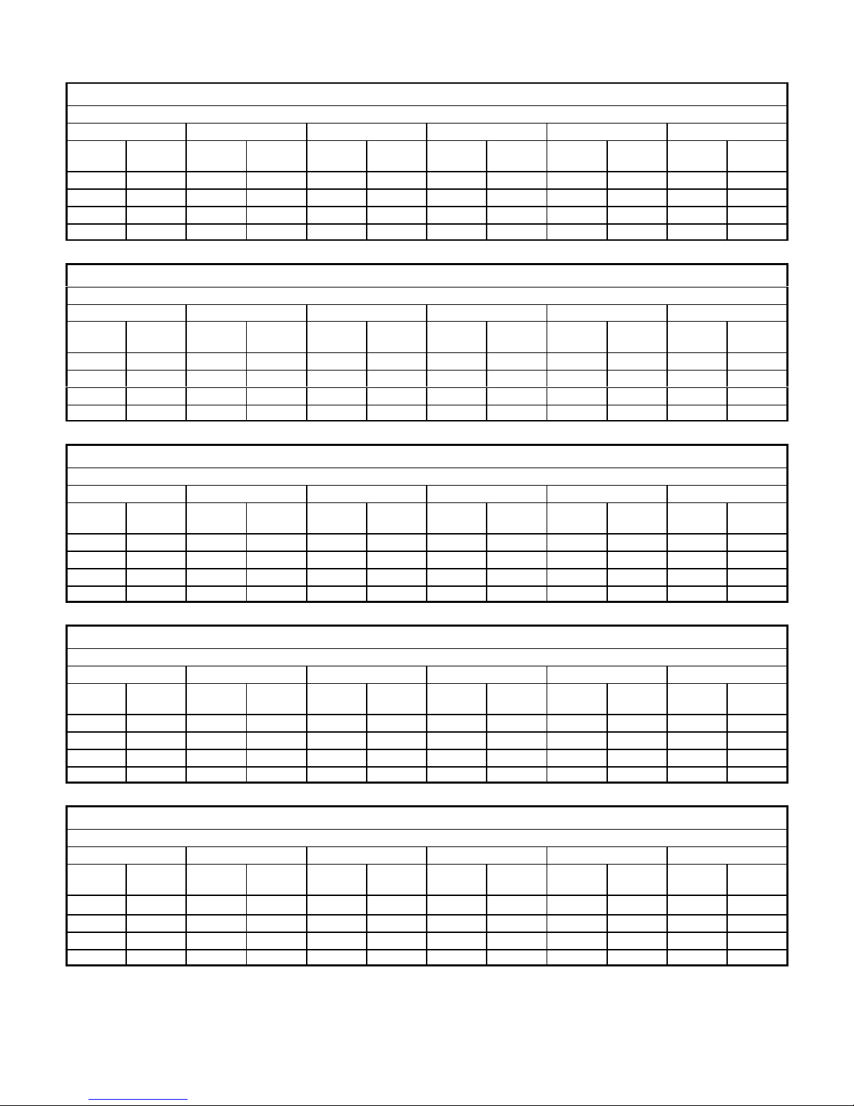
TABLE 15
KGB/KCB030 Normal Operating Pressures
Outdoor Coil Entering Air Temperature
65 °F 75 °F 85 °F 95 °F 105 °F 115 °F
Suct
(psig)
118 227 118 271 119 316 121 365 123 422 125 486
126 230 128 266 129 309 130 367 131 425 134 493
144 235 147 272 150 312 151 358 151 417 153 488
163 245 167 279 171 319 173 363 176 412 177 465
Disc
(psig)
Suct
(psig)
Disc
(psig)
Suct
(psig)
Disc
(psig)
Suct
(psig)
Disc
(psig)
Suct
(psig)
Disc
(psig)
Suct
(psig)
Disc
(psig)
TABLE 16
KGB/KCB036 Normal Operating Pressures
Outdoor Coil Entering Air Temperature
65 °F 75 °F 85 °F 95 °F 105 °F 115 °F
Suct
(psig)
114 237 115 271 117 317 11 9 369 122 426 124 503
122 238 123 269 126 318 128 366 130 422 133 492
141 246 144 277 146 321 148 369 149 425 152 489
162 254 165 287 168 330 171 377 173 428 176 497
Disc
(psig)
Suct
(psig)
Disc
(psig)
Suct
(psig)
Disc
(psig)
Suct
(psig)
Disc
(psig)
Suct
(psig)
Disc
(psig)
Suct
(psig)
Disc
(psig)
TABLE 17
KGB/KCB048 Normal Operating Pressures
Outdoor Coil Entering Air Temperature
65 °F 75 °F 85 °F 95 °F 105 °F 115 °F
Suct
(psig)
114 251 116 285 117 334 11 9 382 121 436 123 500
122 255 125 292 127 336 128 385 130 439 132 502
139 265 142 300 145 343 148 391 150 440 153 499
155 277 159 313 164 356 167 403 171 454 174 510
Disc
(psig)
Suct
(psig)
Disc
(psig)
Suct
(psig)
Disc
(psig)
Suct
(psig)
Disc
(psig)
Suct
(psig)
Disc
(psig)
Suct
(psig)
Disc
(psig)
TABLE 18
KGB/KCB 060 Normal Operating Pressures
Outdoor Coil Entering Air Temperature
65 °F 75 °F 85 °F 95 °F 105 °F 115 °F
Suct
(psig)
110 239 112 284 114 329 11 6 379 118 437 120 532
118 242 121 286 123 329 125 379 127 433 130 495
136 252 139 294 141 337 144 382 147 435 152 488
153 265 158 304 161 345 163 390 165 442 173 494
Disc
(psig)
Suct
(psig)
Disc
(psig)
Suct
(psig)
Disc
(psig)
Suct
(psig)
Disc
(psig)
Suct
(psig)
Disc
(psig)
Suct
(psig)
Disc
(psig)
TABLE 19
KGA/KCA 072 Normal Operating Pressures
Outdoor Coil Entering Air Temperature
65 °F 75 °F 85 °F 95 °F 105 °F 115 °F
Suct
(psig)
106 250 111 288 11 5 329 11 8 375 121 428 124 482
110 256 116 295 122 338 126 383 129 434 132 490
124 254 130 309 135 351 141 398 146 449 149 508
138 289 145 329 151 373 157 422 163 473 169 527
Disc
(psig)
Suct
(psig)
Disc
(psig)
Suct
(psig)
Disc
(psig)
Suct
(psig)
Disc
(psig)
Suct
(psig)
Disc
(psig)
Suct
(psig)
Disc
(psig)
Page 45
507348-04 12/2015
Page 46

TABLE 20
KGB/KCB 074S & H Normal Operating Pressures
Outdoor Coil Entering Air Temperature
65 °F 75 °F 85 °F 95 °F 105 °F 115 °F
Suct
(psig)
112 257 113 298 114 348 11 6 403 118 476 121 602
120 261 122 301 123 347 124 403 127 466 129 556
136 271 140 310 143 354 145 401 145 460 147 525
154 290 157 327 161 370 165 416 168 468 171 526
Disc
(psig)
Suct
(psig)
Disc
(psig)
Suct
(psig)
Disc
(psig)
Suct
(psig)
Disc
(psig)
Suct
(psig)
Disc
(psig)
Suct
(psig)
Disc
(psig)
TABLE 21
KGA/KCA 090 Normal Operating Pressures
Outdoor Coil Entering Air Temperature
65 °F 75 °F 85 °F 95 °F 105 °F 115 °F
Suct
(psig)
107 268 109 309 113 357 11 6 403 11 8 449 123 503
115 275 118 314 120 358 123 406 126 458 130 513
131 286 134 327 137 376 140 421 144 477 147 537
147 307 151 344 154 390 158 441 162 495 167 558
Disc
(psig)
Suct
(psig)
Disc
(psig)
Suct
(psig)
Disc
(psig)
Suct
(psig)
Disc
(psig)
Suct
(psig)
Disc
(psig)
Suct
(psig)
Disc
(psig)
Liquid Temperature (° F)
120
110
100
90
80
70
KGB/KCB 024 Charging Curves
Outdoor Temperature (°F)
115°
105°
95°
85°
75°
65°
60
110 120 130 140 150 160 170
KG/KC 024, 030, 036, 048, 060, 072, 074, 090
Suction Pressure (psig)
180
Page 46
Page 47

120
KGB/KCB 030 Charging Curves
Outdoor Temperature (°F)
115°
110
100
90
80
Liquid Temperature (° F)
70
60
110 120 130 140 150 160 170
Suction Pressure (psig)
105°
95°
85°
75°
65°
180
Liquid Temperature (° F)
130
120
110
100
90
80
70
KGB/KCB 036 Charging Curves
Outdoor Temperature (°F)
115°
105°
95°
85°
75°
65°
60
110 120 130 140 150 160 170
Suction Pressure (psig)
180
Page 47
507348-04 12/2015
Page 48

130
KGB/KCB 048 Charging Curves
Outdoor Temperature (°F)
115°
120
110
100
90
Liquid Temperature (° F)
75°
80
70
65°
110 120 130 140 150 160 170
Suction Pressure (psig)
105°
95°
85°
180
Liquid Temperature (° F)
130
120
110
100
90
80
70
KGB/KCB 060 Charging Curves
65°
Outdoor Temperature (°F)
115°
105°
95°
85°
75°
60
110 120 130 140 150 160 170
KG/KC 024, 030, 036, 048, 060, 072, 074, 090
Suction Pressure (psig)
180
Page 48
Page 49

130
120
KGA/KCA 072 Charging Curves
Outdoor Temperature (°F)
115°
110
100
Liquid Temperature (° F)
90
80
70
60
130
100
105°
95°
85°
75°
65°
110 120 130 140 150 160 170
Suction Pressure (psig)
KGB/KCB074S & H Charging Curves
Outdoor Temperature (°F)
115°
120
110
100
95°
85°
75°
Liquid Temperature (° F)
90
80
70
65°
60
110 120 130 140 150 160 170 180
Suction Pressure (psig)
105°
Page 49
507348-04 12/2015
Page 50
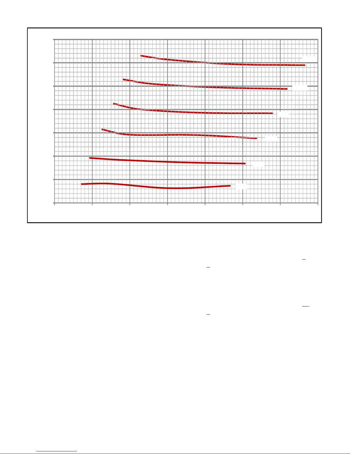
130
KGA/KCA 090 Charging Curves
Outdoor Temperature (°F)
120
110
100
95°
90
85°
Liquid Temperature (° F)
80
75°
70
65°
60
100 110 120 130 140 150 160 170
Suction Pressure (psig)
115°
105°
F-Compressor Controls
See unit wiring diagram to determine which controls are
used on each unit. Optional controls are identified on
wiring diagrams by arrows at junction points.
1- Freezestat (S49)
Switch de-energizes compressor when evaporator
coil temperature falls below 29°F (-2°C) to prevent
evaporator freeze-up. Switch resets when
evaporator coil temperature reaches 58°F (15°C).
2- High Pressure Switch (S4)
High pressure switches are SPST N.C. switches
which open on a pressure rise. The switch is a
manual reset switch on KGA/KCA036, 048, 060 &
090 units. The switch is an auto-reset switch on
KGB/KCB024-074 and KGA/KCA072 units.
S4 is wired in series with the compressor contactor
coil and is located on the compressor discharge line.
When discharge pressure rises to 640+
(4412+
the switch opens. The respective compressor is
de-energized but the economizer can continue to
operate.
Auto-reset switches close at 475+2
(3275+
3- Compressor High Temperature Limit (S5)
S5 is located on the top of Interlink compressors and
is wired in series with the high pressure switch S4.
69kPa), indicating a problem with the system,
138kPa)
10psig
0psig
KG/KC 024, 030, 036, 048, 060, 072, 074, 090
Page 50
Page 51

Gas Heat Start-Up (Gas Units)
FOR YOUR SAFETY READ BEFORE LIGHTING
WARNING
Electric shock hazard. Can cause injury
or death. Do not use this unit if any part
has been under water. Immediately call
a qualified service technician to inspect
the unit and to replace any part of the
control system and any gas control
which has been under water.
WARNING
Danger of explosion. Can cause injury
or product or property damage. If over
heating occurs or if gas supply fails to
shut off, shut off the manual gas valve
to the appliance before shutting off
electrical supply.
WARNING
SMOKE POTENTIAL
The heat exchanger in this unit could be a source of
smoke on initial firing. Take precautions with re
spect to building occupants and property. Vent ini
tial supply air outside when possible.
This unit is equipped with an automatic spark ignition
system. There is no pilot. In case of a safety shutdown,
move thermostat switch to OFF and return the thermostat
switch to HEAT to reset ignition control.
A-Placing Unit In Operation
WARNING
Danger of explosion and fire. Can cause
injury or product or property damage.
You must follow these instructions
exactly.
Gas Valve Operation (figure 24 and 25)
1- Set thermostat to lowest setting.
2- Turn off all electrical power to appliance.
3- This appliance is equipped with an ignition device
which automatically lights the burner. Do not try to
light the burner by hand.
4- Open the control access panel.
HONEYWELL VR8215S GAS VALVE
MANIFOLD
PRESSURE
ADJUSTMENT
SCREW
Single-Stage
MANIFOLD
PRESSURE
OUTLET
WARNING
Electric shock hazard. Can cause
injury or death. Before attempting to
perform any service or maintenance,
turn the electrical power to unit OFF at
disconnect switch(es). Unit may have
multiple power supplies.
BEFORE LIGHTING smell all around the appliance area
for gas. Be sure to smell next to the floor because some
gas is heavier than air and will settle on the floor.
The gas valve may be equipped with either a gas control
lever or gas control knob. Use only your hand to push
the lever or turn the gas control knob. Never use tools. If
the the lever will not move or the knob will not push in or
turn by hand, do not try to repair it. Call a qualified
service technician. Force or attempted repair may
result in a fire or explosion.
WARNING
Danger of explosion. Can cause injury or
death. Do not attempt to light manually.
Unit has a direct spark ignition system.
INLET
PRESSURE
PORT
INLET
PRESSURE
TAP
Gas valve switch shown in ON position.
FIGURE 24
WHITE RODGERS 36J54 GAS VALVE
Two- Stag e
MANIFOLD
PRESSURE TAP
Gas valve switch is shown in OFF position.
FIGURE 25
HIGH FIRE
ADJUSTMENT
LOW FIRE
ADJUSTMENT
Page 51
507348-04 12/2015
Page 52
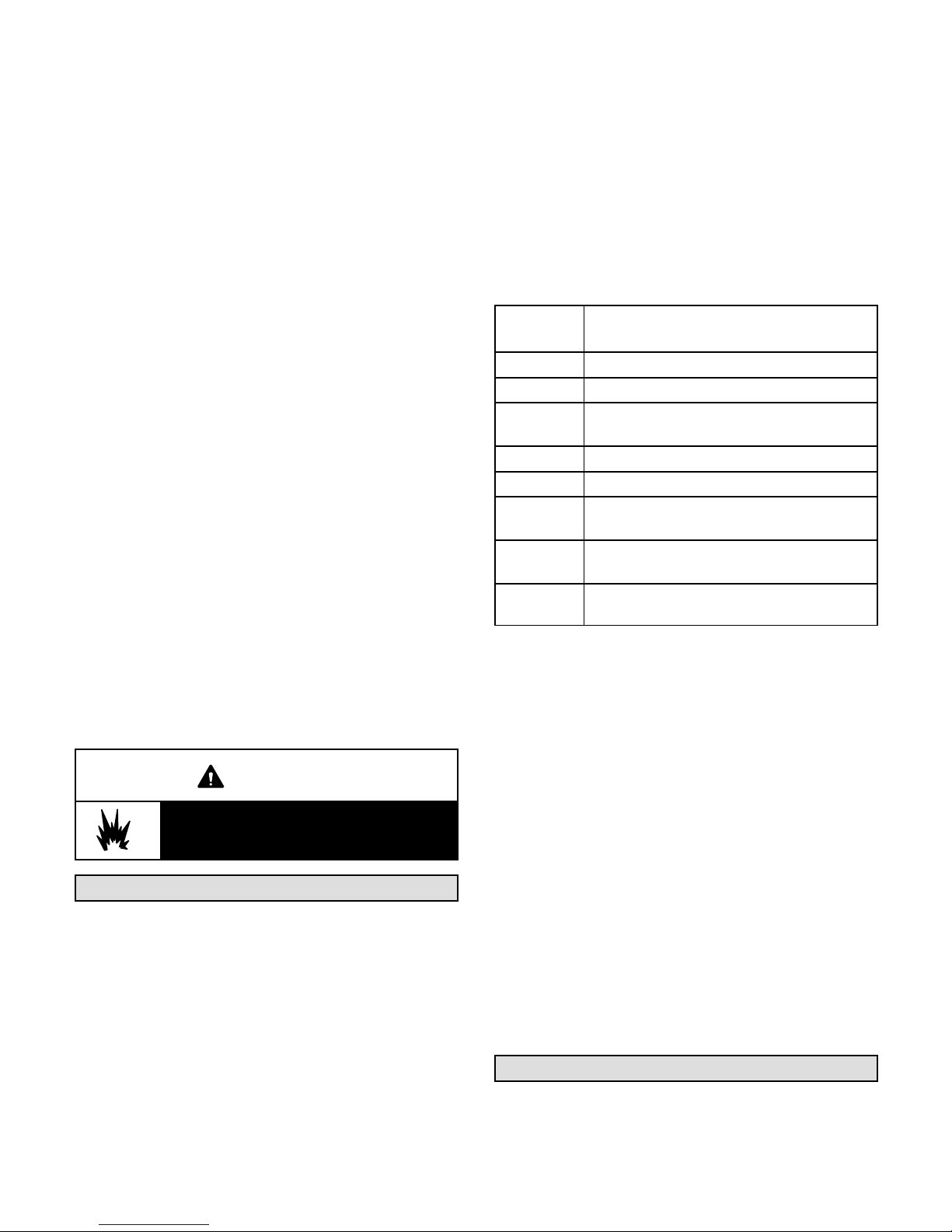
5- Move gas valve switch to OFF. See figure 24 or 25.
6- Wait five (5) minutes to clear out any gas. If you then
smell gas, STOP! Immediately call your
gas supplier from a neighbor's phone. Follow the gas
supplier's instructions. If you do not smell gas, go to
the next step.
7- Move gas valve switch to ON. See figure 24 or 25.
8- Close the control access panel.
5- If flame is not detected after first ignition trial, ignition
control will repeat steps 3 and 4 two more times
before locking out the gas valve.
6- For troubleshooting purposes, an ignition attempt
after lock out may be re-established manually. Move
thermostat to “OFF” and return thermostat switch to
“HEAT” position.
B-Ignition Control Diagnostic LED's
9- Turn on all electrical power to appliance.
10- Set thermostat to desired setting.
NOTE - When unit is initially started, steps 1 through 9
may need to be repeated to purge air from gas line.
11- The ignition sequence will start.
12- If the furnace does not light the first time (gas line not
fully purged), it will attempt up to two more ignitions
before locking out.
13- If lockout occurs, repeat steps 1 through 10.
14- If the appliance will not operate, follow the
instructions “Turning Off Gas to Appliance” and call
your service technician or gas supplier.
Turning Off Gas to Unit
1- If using an electromechanical thermostat, set to the
lowest setting.
2- Before performing any service, turn off all electrical
power to the appliance.
3- Open or remove the control access panel.
4- Move gas valve switch to OFF.
5- Close or replace the control access panel.
IGNITION CONTROL HEARTBEAT LED STATUS
LED
Flashes
Slow Normal operation. No call for heat.
Fast Normal operation. Call for heat.
Steady Off
Steady On Control internal failure.
2 Lockout. Failed to detect or sustain flame.
3
4
5
C-Limit Controls
Limit controls are factory-set and are not adjustable. The
primary limit is located to the right of the combustion air
inducer. See figure 30.
Internal control fault OR no power to
control OR Gas Valve Relay Fault.
Prove switch open or closed or rollout
switch open.
Limit switch is open and/or high limit has
opened three times.
Flame sensed but gas valve solenoid
not energized.
TABLE 22
Indicates
WARNING
Danger of explosion. Can cause injury or
death. Do not attempt to light manually.
Unit has a direct spark ignition system.
Heating Operation and Adjustments
(Gas Units)
A-Heating Sequence of Operation
1- On a heating demand the combustion air inducer
starts immediately.
2- Combustion air pressure switch proves inducer
operation. After a 30-second pre-purge, power is
allowed to ignition control. Switch is factory set and
requires no adjustment.
3- Spark ignitor energizes and gas valve solenoid
opens.
4- Spark ignites gas, ignition sensor proves the flame
and combustion continues.
KG/KC 024, 030, 036, 048, 060, 072, 074, 090
If the primary limit trips three times in the same heating
cycle, heating operation will de-energize. Heating will
automatically restart after one hour if a heating demand is
present. To initiate heating during the one hour timed-off
interval, reset the thermostat.
D-Heating Adjustment
Main burners are factory-set and do not require
adjustment.
The following manifold pressures are listed on the gas valve.
Natural Gas Units - Low Fire - 2.0” w.c.
Natural Gas Units - High Fire - 3.5” w.c.
LP Gas Units - Low Fire - 5.9” w.c.
LP Gas Units - High Fire - 10.5” w.c.
Electric Heat Start-Up (KC Units)
Optional electric heat will stage on and cycle with
thermostat demand. See electric heat wiring diagram on
unit for sequence of operation.
Page 52
Page 53

Service
The unit should be inspected once a year by a qualified
service technician.
CAUTION
Label all wires prior to disconnection when servic
ing controls. Wiring errors can cause improper and
dangerous operation. Verify proper operation after
servicing.
WARNING
The State of California has determined that this
product may contain or produce a chemical or
chemicals, in very low doses, which may cause se
rious illness or death. It may also cause cancer,
birth defects, or reproductive harm.
REMOVE FILTERS
PULL TO
REMOVE
FILTERS
A-Filters
Units are equipped with temporary filters which must be
replaced prior to building occupation. See table 23 for
correct filter size. Refer to local codes or appropriate
jurisdiction for approved filters.
WARNING
Units are shipped from the factory with temporary
filters. Replace filters before building is occupied.
Damage to unit could result if filters are not re
placed with approved filters. Refer to appropriate
codes.
Approved filters should be checked monthly and
replaced when necessary. Take note of air flow direction
marking on filter frame when reinstalling filters. See
figure 26.
TABLE 23
UNIT FILTERS
Unit Qty
KGA/KCA036, 048, 060
KGB/KCB024, 030, 036, 048
KGA/KCA072, 090
KGB/KCB060, 072, 074
Filter Size - in.
4
4
16 X 20 X 2
(406 X 508 X 51)
20 X 20 X 2
(508 X 508 X 51)
(mm)
FIGURE 26
C-Burners (Gas Units)
Periodically examine burner flames for proper
appearance during the heating season. Before each
heating season examine the burners for any deposits or
blockage which may have occurred.
Clean burners as follows:
1- Turn off both electrical power and gas supply to unit.
2- Remove blower access panel.
3- Remove top burner box panel.
4- Remove two screws securing burners to burner
support and lift the burners from the orifices. See
figure 27. Clean as necessary.
BURNER BOX ASSEMBLY
FLAME
SENSOR
GAS VALVE
NOTE-Filters must be U.L.C. certified or equivalent for
use in Canada.
B-Lubrication
All motors are lubricated at the factory. No further
lubrication is required.
BURNERS
GAS
MANIFOLD
IGNITOR
FIGURE 27
Page 53
507348-04 12/2015
Page 54
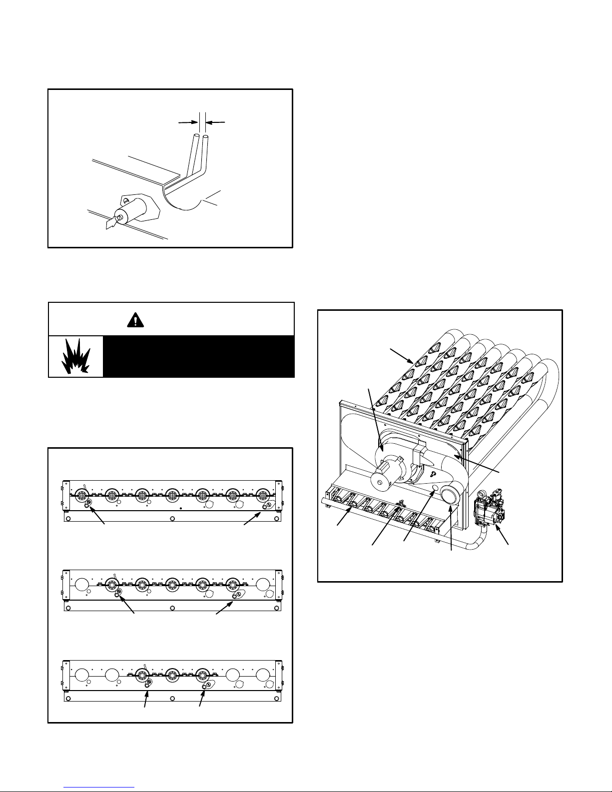
5- Locate the ignitor under the right burner. Check
ignitor spark gap with appropriately sized twist drills
or feeler gauges. See figure 28.
IGNITOR
SPARK GAP
SHOULD BE 1/8”
(3mm)
FIGURE 28
6- Replace burners and screws securing burner. See
figure 29.
WARNING
Danger of explosion. Can cause injury or
death. Do not overtighten main burner
mounting screws. Snug tighten only.
7- Replace access panel.
8- Restore electrical power and gas supply. Follow
lighting instructions attached to unit and use
inspection port in access panel to check flame.
D-Combustion Air Inducer (Gas Units)
A combustion air proving switch checks combustion air
inducer operation before allowing power to the gas
controller. Gas controller will not operate if inducer is
obstructed.
Under normal operating conditions, the combustion air
inducer wheel should be checked and cleaned prior to the
heating season. However, it should be examined
periodically during the heating season to establish an
ideal cleaning schedule.
Clean combustion air inducer as follows:
1- Shut off power supply and gas to unit.
2- Remove the mullion on the right side of the heat
section.
3- Disconnect pressure switch air tubing from
combustion air inducer port.
4- Remove and retain screws securing combustion
air inducer to flue box. Remove vent connector.
See figure 30.
HEAT EXCHANGER ASSEMBLY
HEAT
EXCHANGER
TUBE
COMBUSTION
AIR INDUCER
BURNER ORIENTATION
150,000 BTUH - 7 BURNERS
SENSOR IGNITOR
108,000 BTUH - 5 BURNERS
SENSOR IGNITOR
65,000 BTUH - 3 BURNERS
SENSOR IGNITOR
FIGURE 29
FLUE BOX
COVER
BURNER
ROLLOUT
SWITCH
PRIMARY
LIMIT
VENT
CONNECTOR
GAS VALVE
FIGURE 30
5- Clean inducer wheel blades with a small brush and
wipe off any dust from housing. Take care not to
damage exposed fan blades. Clean accumulated
dust from front of flue box cover.
6- Return combustion air inducer motor and vent
connector to original location and secure with
retained screws. It is recommended that gaskets be
replaced during reassembly.
7- Replace mullion.
8- Clean combustion air inlet louvers on blower access
panel using a small brush.
KG/KC 024, 030, 036, 048, 060, 072, 074, 090
Page 54
Page 55

E-Flue Box (Gas Units)
Fin/Tube Coils -
Remove flue box cover only when necessary for
equipment repair. Clean inside of flue box cover and heat
exchanger tubes with a wire brush when flue box cover
has to be removed. Install a new flue box cover gasket
and replace cover. Make sure edges around flue box
cover are tightly sealed.
F-Evaporator Coil
Inspect and clean coil at beginning of each cooling season.
Clean using mild detergent or commercial coil cleaner.
Flush coil and condensate drain with water taking care not
to get insulation, filters and return air ducts wet.
G-Condenser Coil
All-Aluminum Coils -
Clean condenser coil annually with water and inspect
monthly during the cooling season.
Clean the all-aluminum coil by spraying the coil steadily
and uniformly from top to bottom. Do not exceed 900 psi
or a 45 angle; nozzle must be at least 12 inches from the
coil face. Take care not to fracture the braze between the
fins and refrigerant tubes. Reduce pressure and work
cautiously to prevent damage.
Clean condenser coil annually with detergent or
commercial coil cleaner and inspect monthly during the
cooling season.
Condenser coils are made of single and two formed slabs.
On units with two slabs, dirt and debris may become
trapped between the slabs. To clean between slabs,
carefully separate coil slabs and wash them thoroughly.
See figure 31. Flush coils with water following cleaning.
Note - Remove all screws and gaskets prior to cleaning
procedure and replace upon completion.
H-Compressor
If Interlink compressor replacement is necessary, call
1-800-4-LENNOX (1-800-453-6669).
IMPORTANT
Some scroll compressors have an internal vacu
um protector that will unload scrolls when suc
tion pressure goes below 20 psig. A hissing
sound will be heard when the compressor is run
ning unloaded. Protector will reset when low
pressure in system rises above 40 psig. DO NOT
REPLACE COMPRESSOR.
J-Supply Air Blower Wheel
Annually inspect supply air blower wheel for accumulated
dirt or dust. Turn off power before attempting to remove
access panel or to clean blower wheel.
CLEAN FIN/TUBE CONDENSER COIL - KGA/KCA 036, 048, 060
ENDPLATE IS SECURED
TOP VIEW
SUPPLY
AIR
BLOWER
CONDENSER ACCESS PANEL
TO MULLION
CONDENSER
COILS
FIGURE 31
Page 55
1- Remove unit top panel and condenser section access
panel.
2- Remove screws securing coil end plate to mullion.
3- Remove wire ties connecting coil slabs and separate
slabs 3-4” (76-102mm).
4- Clean coils with detergent or commercial coil cleaner.
5- Rinse thoroughly with water and reassemble
6- Secure coil slabs together using field-provided wire
ties.
.
507348-04 12/2015
Page 56

J-Supply Air Blower Replacement
-072H, -074H and -090 Units Only -
1- Peel the rubber seal off of the L-bracket on the blower
deck. See figure 32.
4- Reinstall blower in channels. Secure blower in place
with seven retained screws.
5- Replace L-bracket and reinstall screws from the top,
6- Replace rubber seal.
2- Remove and retain the three screws securing the
L-bracket to the blower deck; remove L-bracket.
3- Remove and retain the seven screws holding the
blower in place. Slide blower out of unit.
REMOVING 072, 074 & 090 UNIT BLOWERS
BLOWER
DECK
SCREWS
SECURING
BLOWER - TWO
ON EACH SIDE
RUBBER
SEAL AND
L-BRACKET
WARNING
Danger of introducing harmful gases into supply
air. Failure to replace rubber seal on blower deck
could result in injury or death.
SCREWS
SECURING
BLOWER
SCREWS
SECURING
L-BRACKET
KG/KC 024, 030, 036, 048, 060, 072, 074, 090
FIGURE 32
Page 56
 Loading...