

Page 1

r
www.PelletKing.com
INSTALLATION AND OPERATION
FREESTANDING
AND INSERT
PELLET FIRED
STOVES
MANUAL
Freestanding Model
Advantage II-T C FS
RETAIN THESE
INSTRUCTIONS
FOR FUTURE
REFERENCE
Freestanding Model
Advantage II-T C INS
These appliances must be properly installed and operated in orde
to prevent the possibility of a house fire. Please read this entire
owner's manual before installing and using your pellet stove. Failure to follow these instructions could result in property damage,
bodily injury or even death. Contact your local building or fire officials to obtain a permit and information on any installation requirements and inspection requirements in your area.
P/N 775096M, Rev. E, 11/03
Page 2

IMPORTANT WARNINGS
www.PelletKing.com
CAUTION:
eration and maintenance instructions exactly without deviation. Failure to follow these instructions may result
in a possible fire hazard and will void the warranty. If this appliance is not properly installed, a house fire may
result. Contact local building or fire officials about requirements and installation inspection in your area.
1. DO NOT CONNECT THIS UNIT TO A CHIMNEY
FLUE CONNECTED TO ANOTHER APPLIANCE.
2. Do not connect this appliance to air ducts or any
air distribution system.
3. Do not install a flue damper in the exhaust venting
system of this appliance.
4. Do not use class B venting intended for gas appliances as a chimney or connector pipe on a pellet
fired appliance.
5. The minimum clearances must be maintained for
all combustible surfaces and materials including;
furniture, carpet, drapes, clothing, wood, papers,
etc. Do not store firewood within this clearance
space.
6. INSTALLATION DISCLAIMER - This stoves exhaust
system works with negative combustion chamber
pressure and a slightly positive chimney pressure.
Therefore, it is imperative that the exhaust system
be gas tight (air tight, sealed connection) and installed correctly. Since Lennox Hearth Products
has no control over the installation of your stove,
Lennox Hearth Products grants no warranty, implied or stated for the installation or maintenance
of your stove, and assumes no responsibility for
any consequential damage(s).
7. Burning any kind of fuel consumes oxygen. If outside air is not ducted to the appliance, ensure that
there is an adequate source of fresh air available to
the room where the appliance is installed.
8. The stove will not operate using natural draft, nor
without a power source for the blower and fuel
feeding systems.
9. Never use gasoline, gasoline-type lantern fuel,
kerosene, charcoal lighter fluid, or similar liquids
to start or "freshen up" a fire in this heater. Keep
all such liquids well away from the heater while it is
in use.
10. CONTINUOUS OPERATION: When operated correctly, this appliance cannot be overfired. Continuous operation at a maximum burn can, however, shorten the life of the electrical components
(blowers, motors, and electronic controls), and is
not recommended. Typical approved operation
would include running at the low to mid range setting with occasional running on the maximum setting during the coldest periods of the winter. The
room air blower speed control should be turned to
high when operating the stove on the high heat
setting.
11. CAUTION: NEVER PUT FINGERS NEAR AUGER.
Pellet fuel is fed to the UltraGrate
ger. This auger is driven by a high torque motor.
Read this manual thoroughly before starting installation. For your safety, follow the installation, op-
The auger is capable of doing serious harm to fin-
gers. Keep pellets in the hopper at all times and
keep fingers away from auger. The auger can start
and stop automatically at any time while the stove
is running.
12. CAUTION: HOT WHILE IN OPERATION. An appliance hot enough to warm your home can severely
burn anyone touching it. Keep children, clothing
and furniture away. Contact may cause skin burns.
Do not let children touch the appliance. Train them
to stay a safe distance from the unit.
13. APPROVED FUEL: This appliance is designed spe-
TM
by a screw au-
cifically for use only with pelletized wood fuels
only. With its advanced UltraGrate
this appliance is designed and approved for the
burning of wood residue pellets with up to 3% ash
content. This appliance is NOT approved to burn
cardboard, nut hulls, cherry pits, corn, etc. regardless if it is in pellet form. Failure to comply with this
restriction will void all warranties and the safety
listing of the stove. Consult with your authorized
Lennox Hearth Products dealer for approved pellet
fuels.
14. FLY ASH BUILD-UP: For all wood pellet fuelburning heaters, the combustion gases will contain
small particles of fly ash. This will vary due to the
ash content of the fuel being burned. Over time,
the fly ash will collect in the exhaust venting system and restrict the flow of the flue gases. The exhaust venting system should be inspected regularly and cleaned as necessary.
15. SOOT FORMATION: Incomplete combustion can
occur during startup, shutdown, or incorrect operation of the room heater. This can lead to some
soot collecting in the exhaust venting system. A
precautionary inspection on a regular basis is advisable to determine the necessity of cleaning. The
exhaust venting system should be inspected regularly and cleaned as necessary.
16. DISPOSING OF ASHES: Any ashes removed from
the pellet stove must be deposited in a metal container with a tight-fitting lid. The closed container
of ashes should be placed on a noncombustible
floor or on the ground, well away from all combustible materials, outside of the dwelling pending final disposal. If the ashes are disposed of by burial
in soil or otherwise locally dispersed, they should
be retained in the closed container until all cinders
have been thoroughly cooled.
17. SAVE THESE INSTRUCTIONS.
18. See the listing label located in the hopper (or see
Safety / Listing Labels on page 43).
TM
technology,
PAGE 2
Page 3

TABLE OF CONTENTS
www.PelletKing.com
Important Warnings ................................................ 2
Testing / Listing, EPA, Using this Manual................ 3
Planning Your Installation ..................................... 4-8
Manufactured (Mobile) Home Installation ................8
Installation .......................................................... 9-20
Care and Operation .......................................... 21-25
Routine Maintenance........................................ 26-30
Specifications.................................................... 31-32
Definitions ...............................................................33
Wiring Diagram .......................................................34
Troubleshooting ................................................ 35-37
Replacement Parts List / Diagrams .................. 38-41
Optional Accessories ..............................................42
Safety / Listing Label...............................................43
EPA and Colorado Compliance Label ....................44
Simple Operating Instructions Label.......................45
Installation Tips Label .............................................46
Ownership Records ................................................47
LISTING / TESTING
Listing: The listing laboratory is ITS (Intertek Testing
Services) and the listing mark is Warnock Hersey.
Testing: In accordance with the specifications and procedures listed in UL 1482 / ULC S627 / CSA B366.2M / ULC
S628 & ASTM E1509 for solid fuel room heater, report #
5515, 12-91and ASTM E1509 Report # 476-1244, 3-96.
This appliance has been independently tested to UL, ULC
and CSA standards. UL 1482 & ULC S627 states requirements for installations as a freestanding room heater,
or hearth insert for masonry fireplaces listed to UBC 37 or
ULC S628, or factory built (zero clearance) fireplaces
listed to UL 127 or ULC S610.The safety-listing label is
located on an inside hopper surface of the pellet stove.
Please read this safety label carefully. It contains important information about installation and operation of this
appliance. This appliance is tested and listed for residential installation according to current national and local
building codes as:
• A Freestanding Room Heater –FS
• A Insert Room Heater – INS
• A Manufactured (mobile) Home Heater – FS & INS
EPA (Environmental Protection Agency)
Status: EPA – Certified to comply with July 1990 particulate emission standards.
PRODUCT IS SUBJECT TO CHANGE WITHOUT NOTICE.
CONGRATULATIONS ON THE PURCHASE OF YOUR
NEW PELLET STOVE MANUFACTURED BY LENNOX
HEARTH PRODUCTS.
When you purchased your new pellet stove, you joined
the ranks of thousands of concerned individuals
whose answer to their home heating needs reflects
their concern for aesthetics, efficiency and our environment. We extend our continued support to help you
achieve the maximum benefit and enjoyment available
from your new pellet stove.
It is our goal at Lennox Hearth Products to provide
you, our valued customer, with an appliance that will
ensure you years of trouble free warmth and pleasure.
Thank you for selecting a Lennox Hearth Products
stove as the answer to your home heating needs.
Sincerely,
All of us at Lennox Hearth Products
PACKAGING LIST
The assembled pellet stove model Advantage II-T C FS and
Advantage II-T C INS are packaged with an accessory package, which contains the following:
One - Installation and operation instructions manual.
One - Warranty.
One - EPA Label.
One - Colorado compliance certificate
One - Power cord.
One - Damper hex wrench
One - Grate scraper/tool.
One - Wall thermostat.
One - Roll of thermostat wire.
Two - Leveling bolts, 3/8"-16 x 3 1/2” (Insert only)
One - Ash pan trim cover
One - Trivet
One - Control board (Insert)
One - Video tape
One - Fireplace warning label (insert only)
One - Damper rod assembly with tag
Surround Kit (For Advantage II-T C INS Only)
(Purchased separately, see page 42) kit is packaged with:
One - Top surround panel.
One - Left surround panel.
One - Right surround panel with door.
Pedestal Kit (For Advantage II-T C FS Only)
(Included with freestanding stove) kit is packaged with:
One - Pedestal assembly.
Three -Bolts, 3/8" x 1/2”.
Three -Washers.
USING THIS MANUAL
Please read and carefully follow all of the instructions
found in this manual. Please pay special attention to the
safety instructions provided in this manual. The homeowner’s Care and Operation Instructions included here will
assure you have many years of dependable and enjoyable
service from your appliance.
PAGE 3
Page 4

PLANNING YOUR INSTALLATION
www.PelletKing.com
QUESTIONS TO ASK LOCAL BUILDING OFFICIAL
A correct installation is critical and imperative for reducing fire hazards and perilous conditions that can arise
when wood pellet burning appliances are improperly
installed. The installer must follow all of the manufacturers’ instructions.
The installation of this appliance must conform to local
codes and applicable state and federal requirements.
Familiarity with these requirements before installation is
essential. Important considerations to discuss with local
building officials include:
1. Applicable codes (i.e. Uniform Mechanical Code,
State or Regional Codes).
Electrical codes:
In USA, NEC, ANSI / NFPA 70 – Latest Edition
In Canada, CSA C22.1 – Latest Edition
Power Supply Requirements
be plugged into a standard, 115 volt, 60 Hz grounded
electrical outlet. The approximate power requirement is
362 Watts, and will peak up to 736 Watts for approximately 6 minutes when the self-igniter is operating (it
will turn off 2 minutes after flame detection). The power
cord must be routed to avoid contact with any of the hot
or sharp exterior surface areas of the stove. When installed into a manufactured (mobile) home, the appliance must be electrically grounded to the steel chassis
(see page 8, Manufactured [Mobile] Home Require-
ments). These requirements must be met unless otherwise specified by state or local authorities.
WARNING - ELECTRICAL GROUNDING INSTRUCTIONS: THIS APPLIANCE IS EQUIPPED
WITH A THREE-PRONG (GROUNDING) PLUG
FOR YOUR PROTECTION AGAINST SHOCK
HAZARD AND SHOULD BE PLUGGED DIRECTLY INTO A PROPERLY GROUNDED
THREE-PRONG RECEPTACLE. DO NOT CUT
OR REMOVE THE GROUNDING PRONG FROM
THIS PLUG. DO NOT ROUTE POWER CORD
UNDER OR IN FRONT OF APPLIANCE.
2. Local amendments?
3. Is a permit required - cost?
You may wish to contact your insurance company
to ask if they require this.
4. Is outside combustion air required?
5. Rooms where the installation is not allowed?
– The power cord must
INSTALLATION / MAINTENANCE STANDARDS
National Fire Protection Association – The primary
NFPA standard that refers to installation and maintenance of pellet appliances and venting is NFPA 211 –
Latest Edition: Chimneys, Fireplaces, Vents, and Solid
Fuel appliances.
SELECTING A LOCATION
The design of your home and where you place your
stove will determine its value as a source of heat. A pellet stove depends primarily on air circulation (convection) to disperse its heat, and therefore, a central location is often best. There are other practical considerations, which must be considered before a final selection
of locations is made.
♦ Existing Chimneys
♦ Pellet Fuel Storage
♦ Aesthetic Considerations
♦ Roof Design (rafter locations & roof pitch)
♦ Room Traffic
♦ Proximity to Combustibles
♦ Electrical Wiring
The installation of this stove will require some research.
Once your options are determined, consult with your
local building department who will be able to give you
the necessary installation requirements for your area (Is
a building permit required? Rooms where installation
may not be allowed, etc.).
WARNING: CHECK ALL LOCAL BUILDING AND
SAFETY CODES BEFORE INSTALLATION. THE INSTALLATION INSTRUCTIONS AND APPROPRIATE
CODE REQUIREMENTS MUST BE FOLLOWED EXACTLY AND WITHOUT COMPROMISE. ALTERATIONS TO THE STOVE ARE NOT ALLOWED. DO
NOT CONNECT THE STOVE TO A CHIMNEY SYSTEM SERVING ANOTHER STOVE, APPLIANCE, OR
ANY AIR DISTRIBUTION DUCT. FAILURE TO FOLLOW THESE INSTRUCTIONS WILL VOID THE
MANUFACTURERS WARRANTY.
SMOKE DETECTORS
Since there are always several potential sources of fire
in any home, we recommend installing smoke detectors. If possible, install the smoke detector in a hallway
adjacent to the room (to reduce the possibility of occasional false activation from the heat produced by the
stove). If your local code requires a smoke detector be
installed within the same room, you must follow the requirements of your local code. Check with your local
building department for requirements in your area.
PAGE 4
Page 5
PLANNING YOUR INSTALLATION
www.PelletKing.com
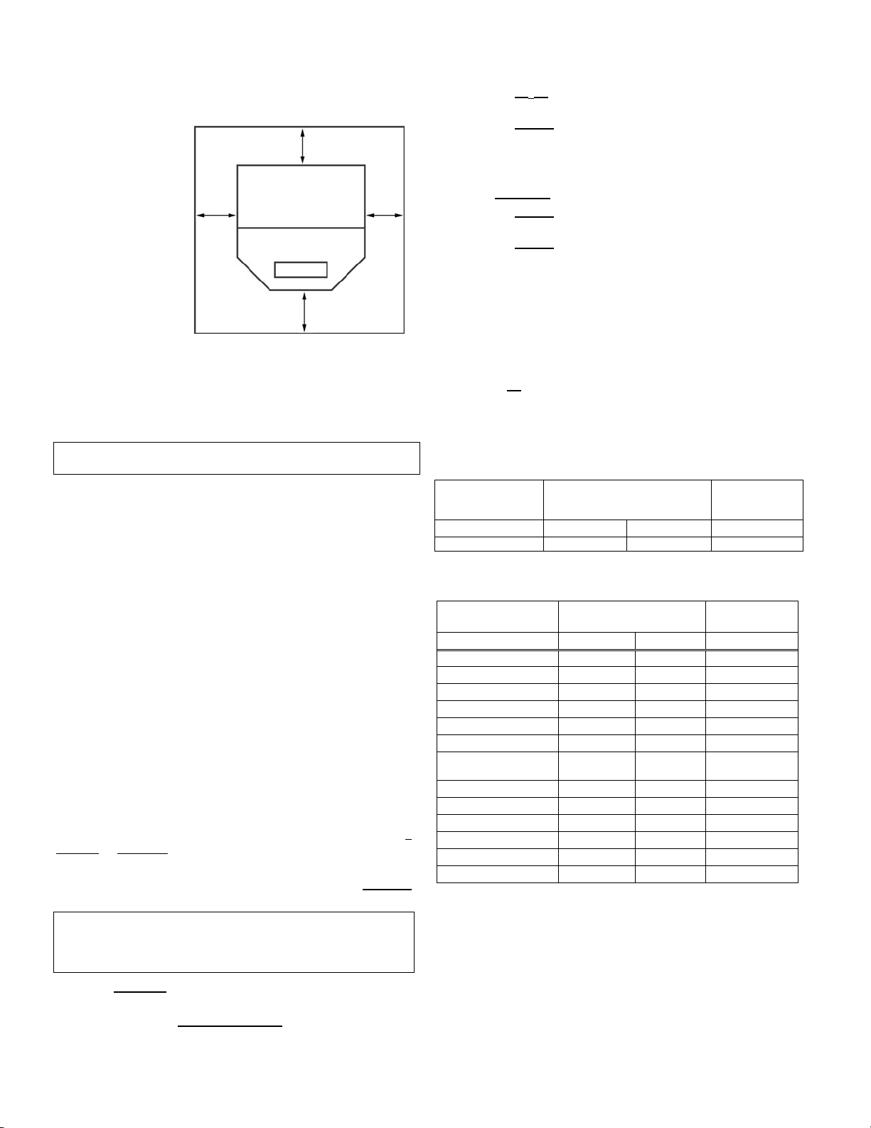
FLOOR PROTECTION – Advantage II-T C FS
(For USA and Canada) This appliance
requires 3/8" (10
mm) minimum noncombustible floor
protection designed
for solid fuel burning
appliances having a
thermal conductivity
of k = .84 BTU in/ft
or equivalent. If the
6”
(153mm)
min.
floor protection is to
be stone, tile, brick,
etc., it must be mortared or grouted to
form a continuous
non-combustible surface (See Using Alternate Material As Floor Protector below).
If a chimney connector extends horizontally over the floor,
protection must cover the floor under the connector and at
least 2" (51 mm) to either side. The floor protector must fully
cover the area beneath the appliance and extend 6” to the
front, 6” to the sides, and up to 6” from the back (see illustration above and following note).
*Note: When installed at clearances less than 6”, the floor
protection is only required to extend to the wall.
FLOOR PROTECTION / HEARTH EXTENSION USING ALTERNATE MATERIAL AS FLOOR PROTECTOR
Floor Protection above for freestanding models and Hearth
Requirements, page 8 for the insert model)
The hearth pad or alternate material used as a floor/hearth
protector must be constructed of a durable noncombustible
material having an equal or better thermal conductivity value
(lower k value) of k = .84 BTU / IN FT
resistance that equals or exceeds r = 1.19 HR °F FT
with a minimum thickness of 3/8”. With these values, determine
the minimum thickness of the alternate material required using
the formula(s) and the table shown here (see chart - Approved
Alternate Materials for Floor/Hearth Protection).
Note: Any noncombustible material having a minimum thickness
of 3/8” (10 mm) whose k value is less than .84 or whose r value is
more than 1.19 is acceptable. If the alternate material used has a
higher k value or lower r value will require a greater thickness of
the material used. In some cases, if the k value is less or the r
value higher, a thinner material may be used.
Methods of determining floor protection equivalents:
To determine the thickness required for the alternate material
when either the k value or r value is known, use either the k
formula or r formula:
Example: Durock Cement
tion. How thick must this material be? The following formulas
give the means of determining minimum thickness required.
= minimum thickness required for alternate material
T
M
kM = k value per inch of alternate material
TL = minimum thickness of listed material
r
= r value per inch of alternate material
M
Using the k formula
Minimum k-value (per Inch) Specified min.
thickness of = of alternate material
alternate k-value (per inch) of listed
material of listed material material
:
is to be used for the floor protec-
Top View
6”
153 mm
(153mm)
6”
153 mm
(also see
2
HR °F or a thermal
x thickness
2
6”
min.
IN/BTU
TM (inches) = kM x T
.84
(inches) = 1.92 x .375 (3/8”)
T
M
.84
L
Answer using k: 2.29 x 0.375” = 0.858 = ~7/8”
7/8” thickness (minimum) Durock Cement will be required.
Using the r formula
(inches) = 1.19 x TL
T
M
r
(inches) = 1.19 x 375 (3/8”)
T
M
.52
:
M
Answer using r: 2.29 x 0. 375” = 0.858 = ~7/8”
7/8” thickness (minimum) Durock Cement will be required.
At times it is important to know what combination of materials are
acceptable for use as floor protection. The “R values” are used to
determine acceptable combinations of materials because “R values” are additive where r and k values are not.
“R value” = 1
k
= r x thickness of material used
Example: Given that the required “R value” for a suitable floor protector used must be equal to or greater than “R” = r x T
.375” = .45.
Listed Material
Listed Material →
Thermal Values
k (per inch) r (per inch) T
.84 1.19 3/8” (.375)
= 1.19 x
L
Specified
Minimum
Thickness
L
Approved Alternate Materials for
Floor/Hearth Protection (**)
Alternative
Materials ↓
k (per inch) r (per inch) TM
Kaowool M Board .47 2.13 * 3/8”
Micore 160
Micore 300
Durock Cement
Hardibacker
Hardibacker 500
Cultered Stone
Hearthstone
Wonderboard 3.23 0.31 1 1/2”
Face brick 9.00 0.11 4 1/8”
Common brick 5.00 0.20
Cement mortar 5.00 0.20 2 1/4”
Ceramic tile 12.5 .08
Marble
Note: To convert inches to millimeters divide by .03937.
* After minimum thickness is calculated, the thickness can be no
less than 3/8” (.375” / 10mm).
(**) If the floor protector to be used is a noncombustible material and is
NOT listed on the chart above, the manufacturer of the material must
provide either the listed k-value per inch or r-value per inch and the
minimum acceptable thickness will need to be calculated per instructions on this page.
Thermal Values * Minimum
.35 2.86 * 3/8”
.46 2.18 * 3/8”
1.92 .52 7/8”
1.95 .51 7/8”
2.30 .44 1 1/8”
2.82 .35 1 5/8”
~20.0 ~.05
Thickness
2 1/4”
5 5/8”
9”
PAGE 5
Page 6
PLANNING YOUR INSTALLATION
www.PelletKing.com
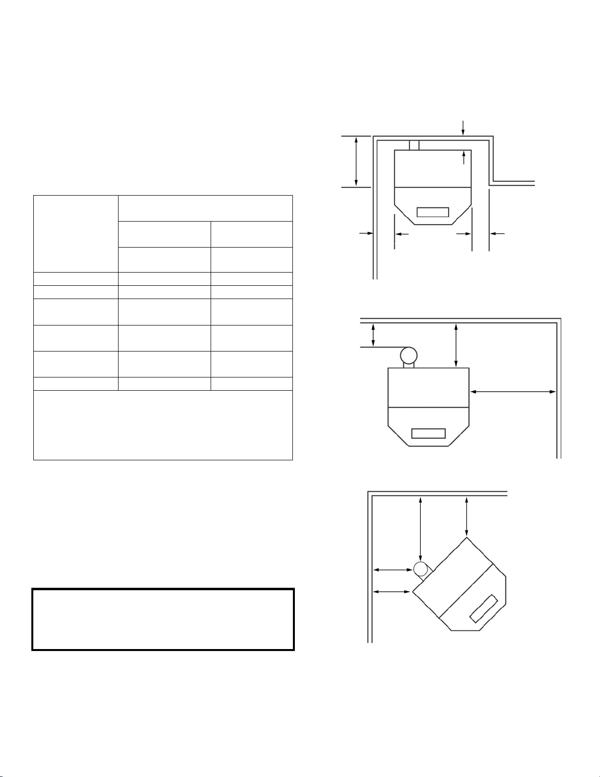
Clearances to combustibles are determined from testing to applicable standards for allowable heat transfer. The clearances allowed as shown here, do not take into account operation or serviceability requirements.
CLEARANCES
Advantage II-T C FS - Standard residential or manufactured (mobile) home installation. These appliances require the following minimum clearances to combustibles:
MINIMUM CLEARANCES TO COMBUSTIBLES
Advantage II-T C
FS
▪ Clearance to
Combustibles
A - Sidewall to unit ♦6” / 153 mm ♦6” / 153 mm
B – Backwall to unit *2” / 50 mm 9” / 230 mm
C – Sidewall to unit
Corner
D - Alcove to Fuel
Hopper
E – Max. Depth of
Alcove
F – Flue to Wall n / a 3” / 77 mm
♦ Measured to fuel hopper
• Alcove Requirements – Minimum Height 50” / 127 cm
Minimum Width 36” / 966 mm
Maximum. Depth 16" / 406 mm
Manufactured (Mobile) Home
or Residential Installation
Horizontal Flue – Directly Through Wall
Interior Vertical Flue
inch / millimeter inch / millimeter
*2” / 50 mm *2” / 50 mm
6” / 150 mm 6” / 150 mm
•16” / 406 mm •16” / 406 mm
Minimum clearances specified may not allow for
ease of operation and maintenance (please take
this in to account when planning the installation).
If installed to the minimum clearances, removal of
the appliance may be necessary for servicing.
• Recommended clearance zone from the front of
the appliance to combustibles is 4 feet minimum.
* The certified back wall clearance as shown on the
listing label is 1" (see Safety / Listing Label) but for
proper hopper lid operation in corner and parallel
installations a 2" clearance is required.
Alcove - Advantage II-T C FS
*B
E
D D
Parallel Wall - Advantage II-T C FS
F
*B
Corner - Advantage II-T C FS
F
C
F
C
A
PAGE 6
Page 7
PLANNING YOUR INSTALLATION
www.PelletKing.com
MASONRY AND FACTORY BUILT FIREPLACES
The model Advantage II-T C INS is approved for installation into a solid fuel burning fireplace, either a masonry
fireplace (built to UBC 37 or ULC S628 standards) or an
approved factory-built / zero clearance fireplace (built to
UL 127 or ULC S610 standards). (see pages 19 through
20 for additional information on venting).
Dimensions Into a Fireplace
Height 20 1/4” / 515 mm
Width 30 1/4” / 768 mm
Depth w/Tee 18 3/8” / 467 mm
Depth–DV thru Masonry Wall 12 1/2” / 318 mm
Recommended clearance zone from the front of the appliance to combustibles is 4 feet minimum.
CAUTION: The fireplace in which the Advantage II-T C
INS is to be installed must be thoroughly cleaned if it
has been used to burn wood or synthetic logs. Have the
chimney and all inside surfaces of the fireplace brushed
and vacuumed so that no soot, embers, or loose combustion deposits can be drawn into the heat circulation
blower and blown into the living area. If any portion of
the chimney system shows signs of structural or mechanical weaknesses, such as: cracks, leaky joints, corroded or warped surfaces, the faulty portion must be
repaired or replaced prior to installing this appliance.
IMPORTANT: When installing model Advantage II-T C
INS into a factory built fireplace or heatform, the air flow
within and around the fireplace shall not be altered by the
installation of the insert (i.e. DO NOT BLOCK louvers or
cooling air inlet or outlet ports, circulating air chambers in
a steel fireplace liner or metal heat circulator). The factory
built firebox must accept the insert without modification
other than removing bolted or screwed together pieces
such as smoke shelf / deflectors, ash lips, screen or door
tracks and damper assemblies. Any fireplace component,
which is removed, must be retained so they can be reinstalled to restore the fireplace to its original operating condition. The removal of any part must not alter the integrity
of the outer shell of the pre-engineered fireplace cabinet
in any way. A Warning Label (provided with appliance)
must be installed in the fireplace firebox so that it shall be
visible upon removal of the fireplace insert (see Fireplace
Warning Label, below). Use RTV high Temperature Silicone as an adhesive to affix the warning label.
Fireplace Warning Label
Provided in accessory package (insert only)
THIS FIREPLACE HAS BEEN ALTERED TO AC-
COMMODATE A FIREPLACE INSERT AND SHOULD
BE INSPECTED BY A QUALIFIED PERSON PRIOR
TO RE-USE AS A CONVENTIONAL FIREPLACE.
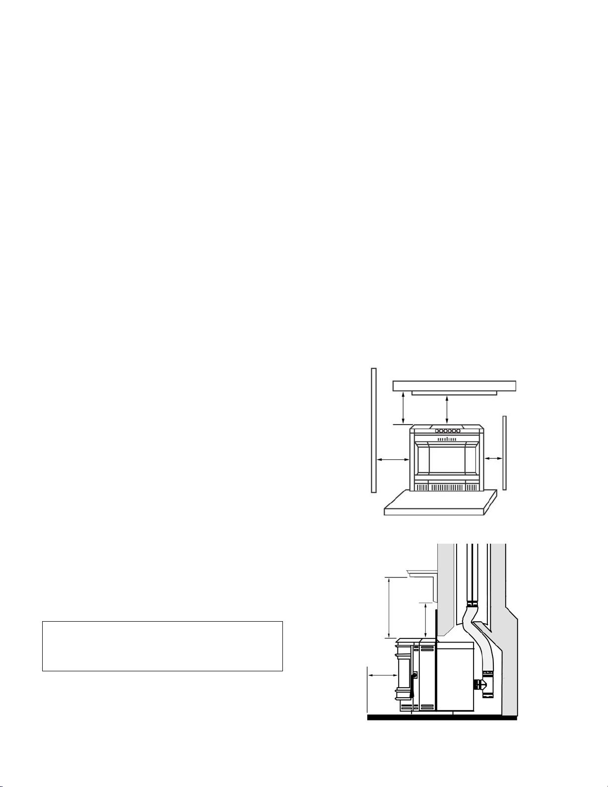
HEARTH / FLOOR PROTECTION - Advantage II-T C
INS
In the USA and Canada, the area below and directly in
front of the Advantage II-T C INS must be an approved
fireplace hearth or protected by a non-combustible
hearth / floor protector with a minimum thickness of 3/8”
which has a thermal conductivity of k (per inch) = .84 or
lower value (better thermal protection) or resistance of r
(per inch) = 1.19 or higher value. See Floor Protection /
Hearth Extension Using Alternate Material as Floor Protector on page 5 which explains minimum thermal pro-
tection requirements.
The protected area must extend 6” to the front of the face
of the Advantage II-T C INS.
MINIMUM CLEARANCES TO COMBUSTIBLES
Masonry and Factory Built Fireplaces
inches / millimeters
A - Insert to side wall 6 “ / 150 mm
B - Insert to side trim 1” / 25 mm
C - Hearth extension 6” / 150 mm
D - Ins e r t t o m a n tel 18” / 457 mm
E - Insert to top trim 1” / 25 mm
D
C
Front View
DE
B
A
Side View
E
PAGE 7
Page 8
PLANNING YOUR INSTALLATION
www.PelletKing.com
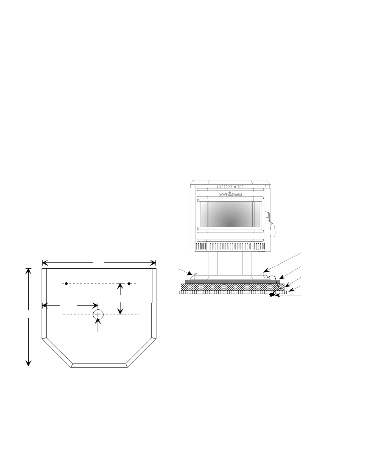
MANUFACTURED (MOBILE) HOME INSTALLATION
Freestanding Model – Advantage II-T C FS
In addition to the standard installation instructions,
the following instructions may be required by local, state or federal building codes:
• Stove must be permanently bolted to the floor.
• An outside air inlet must be provided for com-
bustion and be unrestricted while unit is in use.
Use a galvanized or stainless steel pipe for the
duct (the outside air inlet on the stove is 1 5/8"
diameter).
• Stove must be permanently electrically
grounded to the steel chassis of the home. The
location selected for ground attachment to the
stove must be dedicated for this purpose.
• See pages 13 through 18 for additional informa-
tion on venting requirements.
• Do not install appliance in a sleeping room.
• The structural integrity of the manufactured
home floor, walls, ceiling and roof must be
maintained.
NOTE: The grounding of this product, at installa-
tion, must comply with NFPA-70 standards, CSA C22.1 in Canada, as well as
any local codes.
Model – Advantage II-T C FS
Pedestal Air Inlet
25”
MANUFACTURED (MOBILE) HOME EXHAUST VENT PIPE
INSTALLATION GUIDELINES
Use only “PL” pellet vent pipe listed to UL 641 and ULC
S609. The pipe should extend at least 3 feet above the part
of the roof through which it passes. The top of the pipe
should be at least 2 feet above the highest required elevation
of any part of the manufactured (mobile) home within 10 feet
of the pipe (see page 14, Manufactured [Mobile] Home
Chimney Height Requirements).
If the exhaust vent exits the manufactured (mobile) home at a
location other than the roof, and exits at a point 7 feet or less
above the ground level on which the manufactured (mobile)
home is position a guard or method of enclosing the pipe
shall be provided at the point of exit for a height of up to 7
feet. The openings, if any, in this guard shall not allow a 3/4”
rod to pass through. A 1/2” rod could pass through but should
not be able to touch the pipe when inserted through the opening a distance of 4 inches.
Bolt
Bolt
Floor Protector
Floor
24 ¾”
12 ½”
Outside Air Inlet
1 5/8" diameter
Steel Chassis
Ground
6 7/8”
PAGE 8
To Chassis
Page 9
INSTALLATION
www.PelletKing.com
REMOVING APPLIANCE FROM PALLET
1. After removing the packaging from the stove, lift the
hopper lid, and remove all pre-packaged items that
were shipped in the hopper. Next, open the stove
door and remove all pre-packaged items.
2. Using a 9/16” socket or open end wrench, remove
the bolts which secure stove to pallet. The bolts are
located on the underside of the wooden pallet.
Underside of Pallet
Remove the two bolts from underneath the pallet.
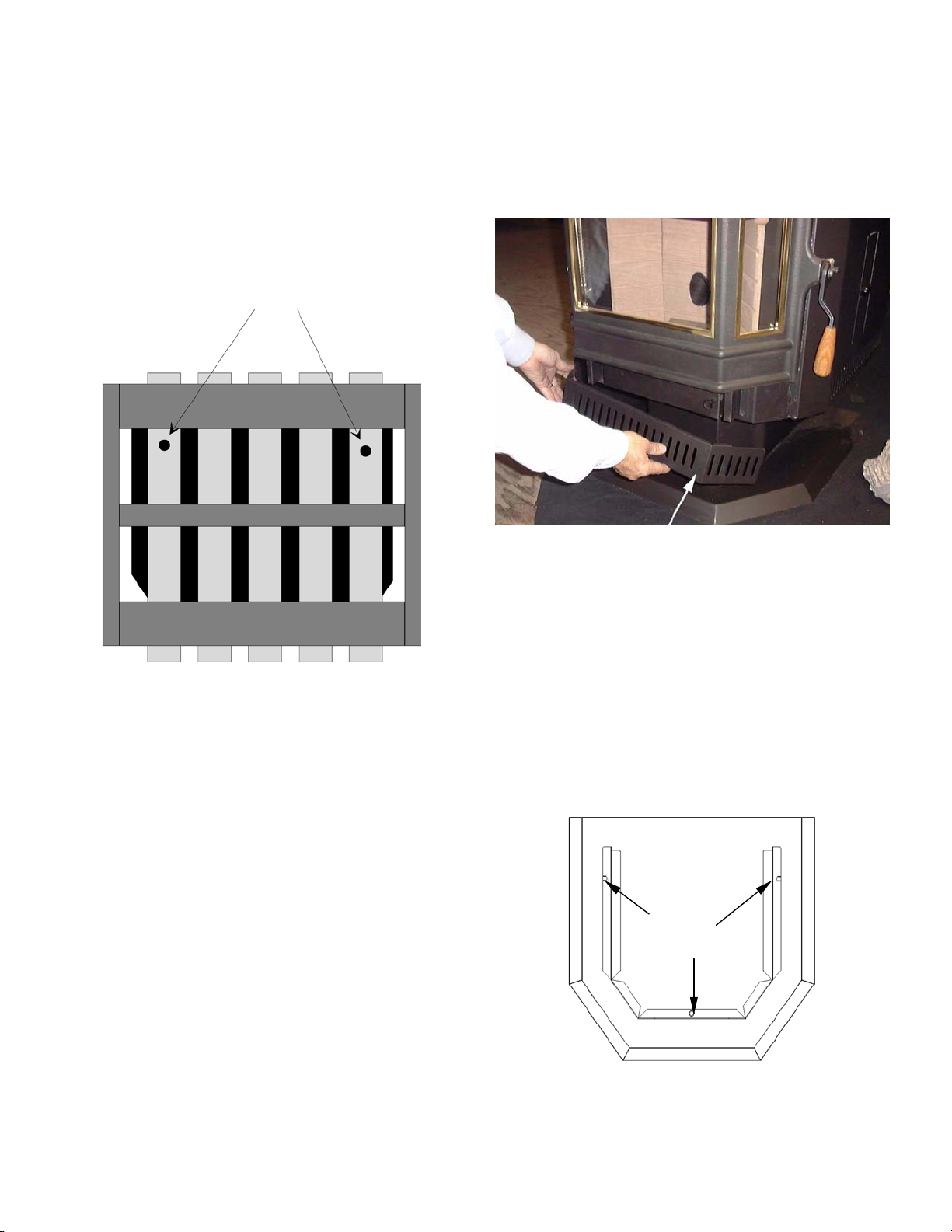
ASH PAN COVER ASSEMBLY
Remove the ash pan cover trim from hopper. Remove
polyfoam wrapping and press into place as shown in illustration below. The ash pan cover trim has two magnets attached which will secure it in place.
NOTE: Bolts may be used in manufactured (mobile)
home installation to permanently secure stove to floor
(see previous page).
Ash Pan Cover
INSTALLING PEDESTAL TO BODY
If your stove is a freestanding model, secure the pedestal to the stove body as follows:
1. Remove the pedestal from the box and place it beside the stove body.
2. Lift the stove onto the pedestal base.
3. Install the three bolts and washers provided through
the holes in the mounting flange of the pedestal and
into the threaded pressed nuts in the stove bottom.
4. Tighten the fasteners using a socket or wrench.
Pedestal – Top View
Install
three bolts
Attach stove to pedestal by inserting three bolts
(provided with pedestal kit)
PAGE 9
Page 10

INSTALLATION
www.PelletKing.com
INSTALLATION CHECK LIST
It is strongly recommended that you have an authorized
Lennox Hearth Products dealer install your stove. If you
install your stove yourself, you should review your installation plan with an authorized Lennox Hearth Products
dealer. Improper installation may void your warranty.
Check list:
Check off each item as you proceed with the installation
process.
Read the ENTIRE stove installation section first
Read the Insert or Freestanding section (whichever
applies).
Determine the appropriate measurements and loca-
tions for your installation.
Follow the general installation directions under Stove
Installation and the installation section appropriate to
your stove.
Be sure to pre-fit all items before you install, fasten,
or set up the stove permanently.
Prior to lighting your stove:
Review the Important Warnings section (page 2).
Review Fuel Specifications (page 25).
Review and follow instructions in the Care and Op-
eration Section (pages 21 to 25).
Plug power cord connector into corresponding con-
nector on the back of appliance (see illustrations on
page 12 showing connector locations).
Note
: Advantage II-T C INS – Route power cord be-
hind side surround panel.
After you have begun operation of your stove:
Review the routine cleaning / maintenance informa-
tion.
Enjoy the warmth from your new Lennox Hearth
Products pellet stove!
Advantage II-T C Insert
It is important to level the appliance. In some installations such as a recessed firebox floor (if the existing fireplace floor is lower than the hearth), install the 2 leveling
bolts (3/8-16 x 3 1/2” long) into the 2 threaded holes at
the rear base of the Advantage II-T C INS. Adjust bolts
until appliance is level.
PAGE 10
Page 11
INSTALLATION
www.PelletKing.com
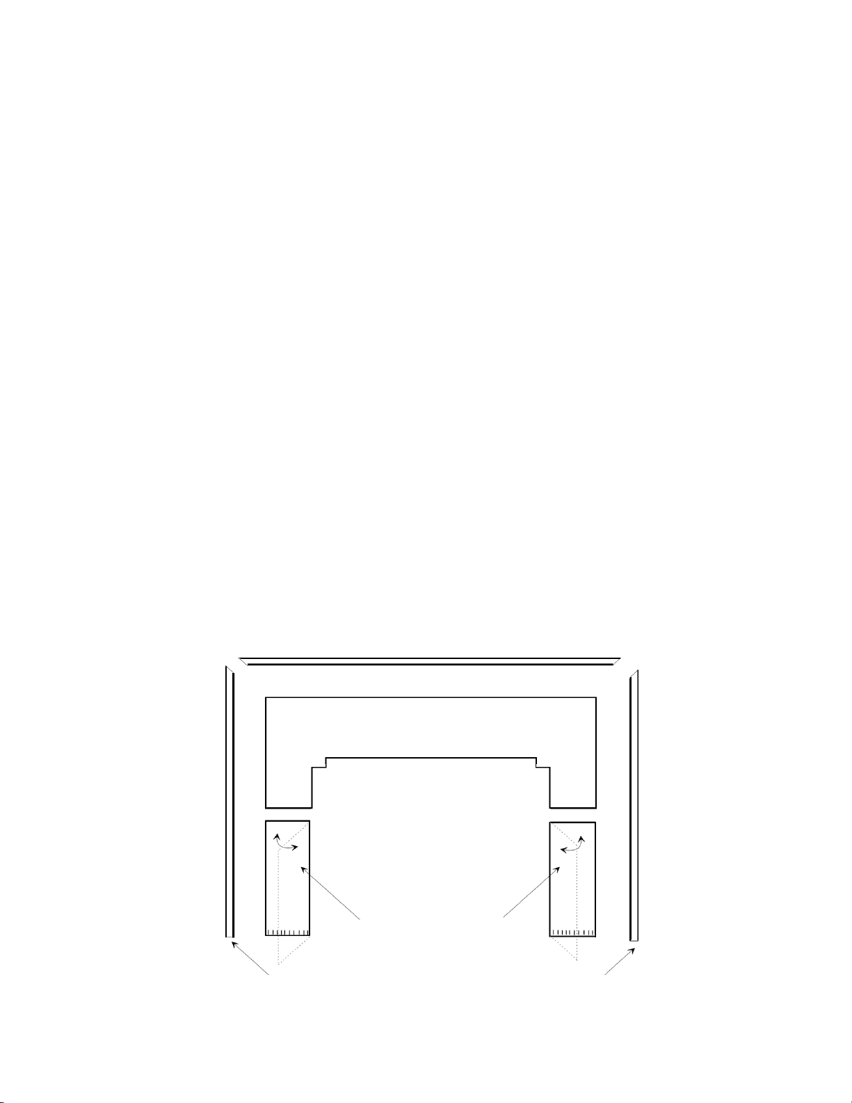
INSTALLING SURROUND ASSEMBLY - Advantage II-T
C INS (to be done after venting system is installed)
The surround kit (purchased separately) comes with a set
of metal panels that enclose the fireplace opening when
fitted together. Put the surround assembly together according to the following instructions (ref. see illustration below).
1. Remove panels from package.
2. Verify that you have all three panels and a package with
“pop” rivets and #8 self-tapping screws. If you do not have
a “pop” rivet tool, you should arrange to buy or borrow one
for this installation.
3. Set the stove on the hearth so that the rear of the stove is
accessible to complete all pipe connections.
4. Verify that the hopper cover is all the way to the front and
open as high as your fireplace opening will allow. Secure
the hopper cover with at least two #8 screws on all three
sides. Tip: Spreading the side panels slightly may be necessary to complete this step.
5. Place four rivets and your “pop” rivet tool beside the stove
and line up the right side panel (with control door) with the
holes in the side of the stove. (When the side panel is
properly installed, the hinge flange will be to the rear of the
stove.) Attach the panel to the stove with four “pop” rivets.
6. Secure the left side surround panel to the stove using the
procedure described in step #5.
7. Before proceeding further, check pipe connections to ensure that all joints are sealed with high-temperature RTV
silicone and properly secured. Refer to detailed venting instructions on pages 16, 19 and 20.
8. The stove may now be pushed into the fireplace cavity to
within 1 1/2” of the face of the fireplace.
9. Set the top surround panel in place over the two side panels. Carefully slide the panel downward into the “U” clips
attached to the back of the Advantage II-T C INS. Tip: Be
careful to align the notched cutouts in the top surround
panel with the stove side panels. Adjust side to side if necessary to align with the surround side panels.
10. Unwrap the control board carefully without touching
any electrical components. Holding the sides of the
control board, lower the bottom edge into the slot in
the bottom of the control door opening Install the
control board onto the right side panel (with door) using the #8 hex head screw provided.
11. Connect the wiring harness from the Advantage II-T C INS
into corresponding connector on control board.
12. Check the Advantage II-T C INS placement in the
fireplace. To reposition, open the door and make any
needed adjustment by pulling forward and then pushing sideways. Once the unit has been centered to
your satisfaction, close the door and push the Advantage II-T C INS back into place so the surround is
flush with the face of the hearth. Tip: Before completing this step, verify that the control board will not
hit the edge of the fireplace opening.
If using the optional gold surround trim, remove the trim
from its packaging and place the piece with the two mitered ends along the top panel. Place the two remaining
side pieces on the surround so that the mitered ends
align. Cut the non-mitered ends of the shroud trim with
scissors, if necessary.
In factory built and masonry fireplaces, a means
must be provided to prevent room air passage to the
chimney cavity of the fireplace. This may be accomplished by sealing the damper area around the chimney liner or pipe.
Top Surround Panel
Left Hinged
Surround Panel
PAGE 11
Right Hinged
Surround Panel
Optional Trim Optional Trim
Page 12
INSTALLATION
www.PelletKing.com
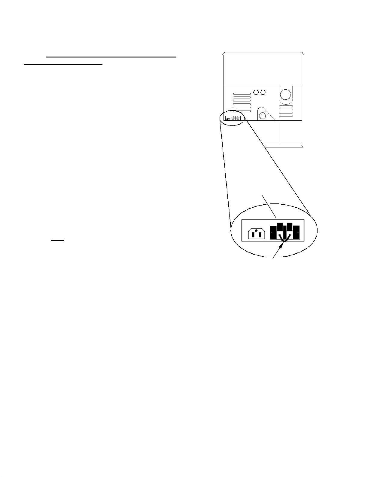
THERMOSTAT INSTALLATION:
NOTE: Always Disconnect Power Before Performing
The Thermostat Installation.
A 24 volt wall thermostat and 20 feet of 18-gage thermostat wire is included in your stove’s accessory package.
It is recommended that the thermostat and thermostat
wire be installed by an authorized Lennox Hearth Products dealer.
Installation Steps:
1. Unplug stove power cord from the wall outlet.
2. Locate the thermostat terminal block on the back of
the stove.
3. Loosen the two terminal screws on the terminal block
and remove jumper.
4. Connect the two wires from your thermostat to the
terminals (one per terminal). Ensure that the purple
wires from the harness remain connected to the terminal block and tighten the terminal screws. Make
sure the wires are firmly connected to the thermostat.
5. Plug in the stove and you are ready to operate with
your thermostat!
IMPORTANT: IF THE WALL THERMOSTAT PROVIDED IS NOT
FOR THE STOVE TO OPERATE
USED, THE JUMPER IS REQUIRED
Rear View of Advantage II-T C FS
Back of Stove
Thermostat
Terminal
Block
Thermostat Jumper
PAGE 12
Page 13

INSTALLATION
www.PelletKing.com
VENTING REQUIREMENTS
It is recommended that only an authorized dealer install
your pellet stove. The specified installation requirements
must be followed to ensure conformity with both the
safety listing of the appliance and local building codes.
All clearances, installation instructions and precautions
specified by the vent manufacturer must be followed.
Selecting a Location (Freestanding Models) - Review
the appliance clearance requirements before installing
the venting system (see page 6). Position the appliance
far enough away from walls to allow adequate room for
servicing. Choose the appliance location with the least
amount of interference with the house framing, plumbing,
wiring, etc.
Preferred Vent Configuration - For the best performance, we recommend a vent run design which runs vertically and terminates above the roofline. This design will
allow natural draft to improve the flow of flue gases and
will aid in combustion and stove performance.
Type of Pipe - This stove requires type “PL” vent pipe
(pellet vent pipe, sometimes referred to as “L-Vent pellet
vent”), listed to UL 641 or ULC S609. Connect the pellet
vent pipe or the “tee” to the flue collar using a minimum
of three screws and seal as specified in “Pipe / Liner
Joint Requirements” on this page. Do not use class B gas
chimney or single wall chimney as a substitute.
Size of Pipe - These pellet appliances are approved for
use with the following vent sizes: 3” (75mm) standard, or
4” (100mm), see page 15 - for determining correct size
vent). When 4” pipe is used: for horizontal vent installations use a 3” (75mm) to 4” (100mm) adapter - available
from vent manufacturer. For vertical installations use a
3” (75mm) to 4” (100mm) “tee” - available from vent
manufacturer.
Note: If installation requires in excess of 11 feet (3 1/3
meter) of pipe, it is recommended that 4” (100 mm) pipe
be used.
Offsets - In every installation, a single or double cleanout “tee” is recommended for every ninety-degree offset
(this tee will help collect ash residue and will allow for
routine cleaning without the need to disconnect sections
of pipe). Note: Offsets and horizontal runs accumulate
fly ash and soot which reduces the exhaust flow and performance of the stove.
Total Offsets in venting system should not exceed 270°
total in direction change.
Horizontal Runs - The maximum total horizontal run
must not exceed 10 feet (3.1 meters).
Horizontal run of pipe requires 1/4” (7 mm) rise per foot.
Pipe Clearances / Requirements - See pipe manufacturers instructions for installation of venting components
and clearances. Follow pipe manufacturers installation
precautions for passing pipe through a combustible wall
or ceiling (i.e. use an approved thimble). Note: Pellet
vent pipe requires 3” (75mm) clearance from outside of
pipe unless otherwise specified by vent manufacturer all diameters: 3” (75mm) and 4” (100mm). A support
bracket must be installed every 4’ (1.2m) of pellet vent
pipe on the exterior wall of the house unless otherwise
specified by vent manufacturer.
Pipe / Liner Joint Requirements - All pipe joints must
be secured with a minimum of 3 screws. ALL horizontal
joints must be sealed gas tight (air tight, sealed connection). Use RTV high temperature silicone or Interam to
provide a complete seal at the flue collar and on all
joints.
Connection to Masonry Chimney through a Wall
(Freestanding Models) - Be sure to verify the construc-
tion of a masonry chimney, as it may have combustible
framing.
Approved liner when relining Masonry or Factory
Built Fireplaces is 2100HT (degree F.) liner listed to
UL 1777 or ULC S635.
Connection to an Existing Class A Chimney (Freestanding Models) - A chimney adapter can be used to
make the connection from 3” (75mm) or 4” (100mm) pellet vent pipe (listed to UL 641 or ULC S609) to existing
UL chimney system. Verify with the pipe manufacturer
that your pipe brands will interconnect.
Horizontal-Vent Installations - On all horizontal-vent
installations (short, horizontal runs with no vertical pipe);
care should be taken when choosing a location for terminating the vent. It is not recommended to directly vent
the exhaust on the prevailing wind side of the house. It is
recommended that when an appliance is vented directly
through a wall, a minimum of 8’ (2.5m) of vertical pipe
should be installed to create some natural draft. This will
reduce the possibility of smoke or odor entering the
dwelling during appliance shutdown or loss of power.
PAGE 13
Page 14
INSTALLATION
ON C
GHES
www.PelletKing.com
VENT TERMINATION
Do not terminate vent in an enclosed or semi-enclosed
area such as: carports, garage, attic, crawl space, under
a deck, porch, narrow walkway, closely fenced area, or
any location that can build up a concentration of fumes
such as a stairwell, covered breezeway etc.
Vent surfaces can get hot enough to cause burns if
touched. Adults should supervise children when they are
in the area of a hot stove. Non-combustible shielding or
guards may be required.
Termination Cap: The termination of the outside chimney of the pellet stove shall be located in accordance
with the following:
A. Higher than 3’ (.92m) above any forced air inlet (air
conditioner, etc.) located within 10’ (3m).
B. Not less than 4’ (1.2m) below, 4’ (1.2m) horizontally
from or 1’ (3.1m) above any gravity air inlet (door,
window, etc.) which flue gases could re-enter the
dwelling.
C. Not less than 2’ (.6m) from combustible materials
such as an adjacent buildings, fences, protruding
parts of the structure, roof overhang, plants and
shrubs, etc. and not less than 7’ (2.1m) above grade
when located adjacent to the public sidewalks (access). The final termination of the exhaust system
must be configured so that flue gases do not jeopardize the safety of people passing by, overheat
combustible portions of nearby structures or enter
the dwelling.
D. Not less than 3’ (.92m) below an eave (maximum
overhang of 3’ (.92m) or any construction that projects more than 2” (51mm) from the plane of the wall.
E. The distance from the bottom of termination to grade
is 12” (305mm) minimum. This is conditional upon
plants and nature of grade surface: Be careful to
choose a location for the vent termination which
does not expose people or shrubs to high heat from
the exhaust gases. The exhaust gases are not hot
enough to ignite grass, plants and shrubs located in
the vicinity of the termination although they should
be a minimum of 3’ (.92m) away. The grade surface
under the termination must not be a lawn.
F. Since sparks may escape from the exhaust pipe of
any stove, use caution when positioning the vent
pipe. Refer to pipe manufacturer’s instructions when
installing and terminating the exhaust. The vent pipe
should be horizontal and never run the pipe in a
downward direction (recommend a 1/4” (7mm) rise
per foot horizontal).
Notes:
• It is not recommended to terminate exhaust vent on
the prevailing wind side of the house.
• It is not recommended using a termination cap
with a screen (fly ash can collect in a screen resulting in blockage).
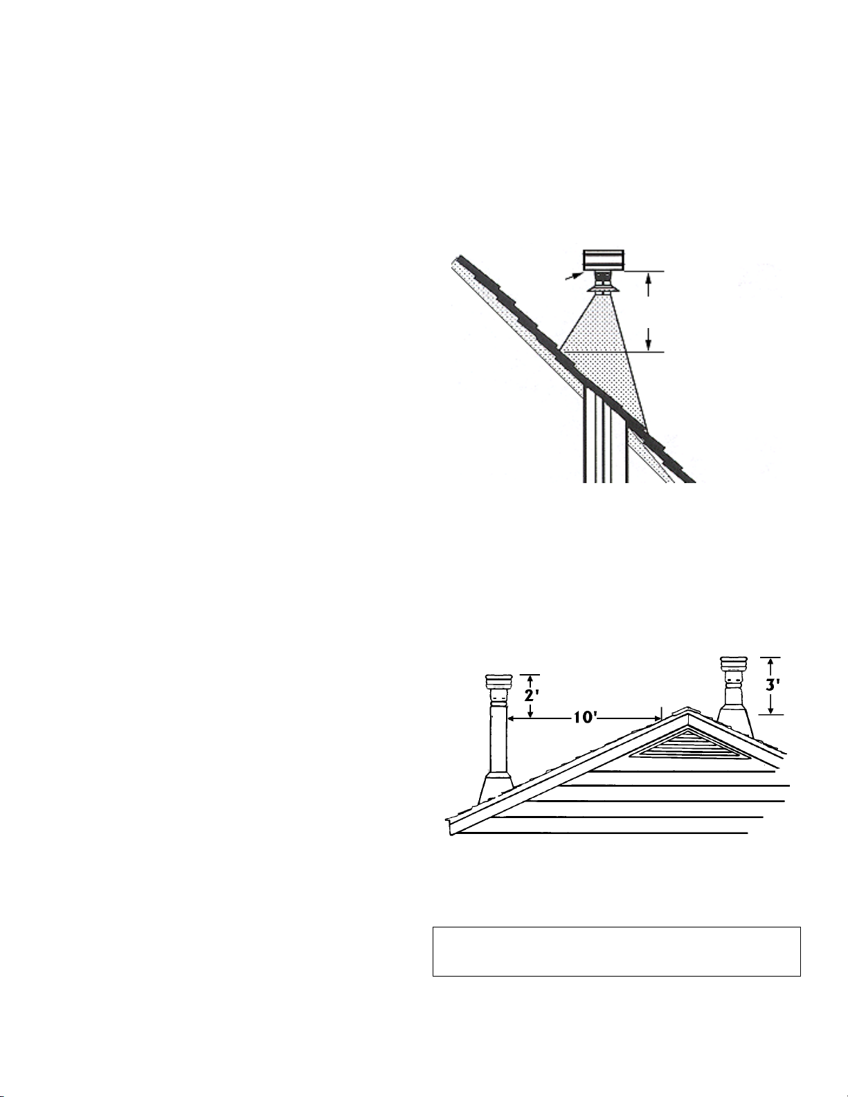
Site Built Residential Home
Chimney Height Requirements
The vent termination height required is - USA, 1-foot
minimum; Canada 3-feet minimum above the roof penetration point as illustrated below (Ref. USA - National
Standard, NFPA 211, Clause 7-4.1 and Canada National
Standard CSA B365-01, Clause 5.6). Check with your
local building official for additional requirements for your
area.
TERMINATION
CAP MUST BE
LISTED TO UL
641 AND ULC
S609 *
USA 1 Foot Minimum
TERMINATION HEIGHT IS
MEASURED ABOVE THE
HIGHEST POINT WHERE
IT PASSES THROUGH
THE ROOF SURFACE.
Manufactured (Mobile) Home
Chimney Height Requirements
The chimney must extend 3’ (.92m) above the level of
roof penetration and a minimum of 2’ (.61m) higher than
any roof surface within 10’ (3m) (see below). Check with
your local building officials for additional requirements for
your area.
REQUIRES A LISTED
TERMINATI
AP *
TOP OF FLUE MUST BE 3’ HIGHER THAN
T POINT OF ROOF PENETRATION
HI
TOP OF FLUE MUST BE 2’
HIGHER THAN ANY PART OF
ROOF WITHIN 10’ HORIZONTAL
To pass inspection in nearly any jurisdiction, the chimney
must meet both safety and exhaust flow requirements.
The (3’ by) 2’ by 10’ rule applies to both masonry and
factory built chimneys.
* Ref. NFPA 211 Clause 7 – 4.1.2, Vents installed with a
listed cap shall terminate in accordance with the terms
of the cap’s listings.
PAGE 14
Page 15
INSTALLATION
r
www.PelletKing.com
DETERMINING SIZE OF PIPE TO INSTALL
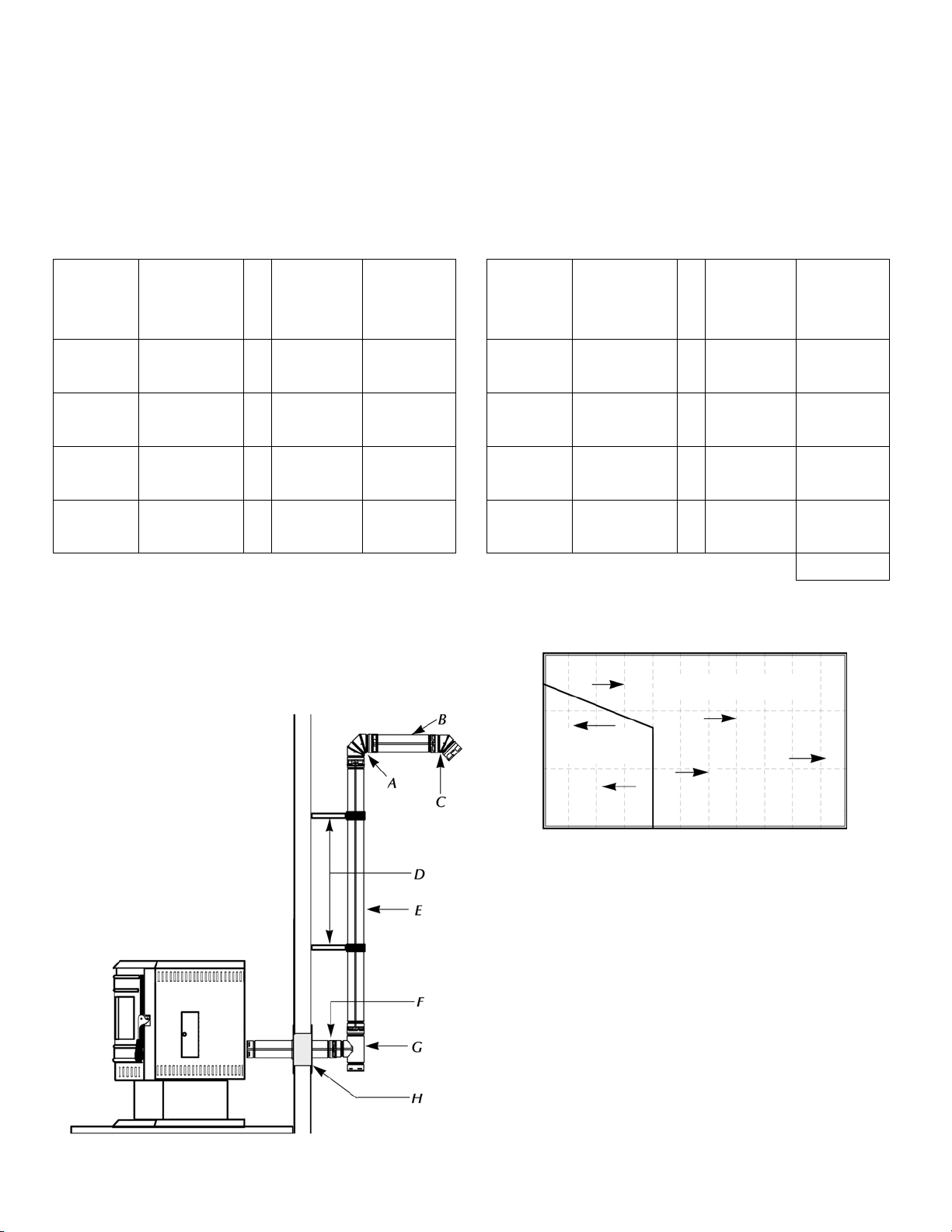
To determine what diameter pipe to use in an installation (3” or 4”), first find the “equivalent pipe length” using the following guidelines, then plot this figure and the altitude on the chart.
Fill out the installation chart, and calculate your total equivalent pipe length. After you have the total equivalent pipe
length, use the Pipe Selection Chart below to determine if your installation requires 3” or 4” exhaust pipe
.
INSTALLATION CHART
Type of
Pipe
# of Elbows
or Feet of
pipe
Equivalent
Feet
Total
Equivalent
Feet
SAMPLE INSTALLATION CHART
Type of
Pipe
# of Elbows
or Feet of
pipe
Equivalent
Feet
Total
Equivalent
Feet
90o Elbows /
Tee (A & G)
o
45
Elbows (C)
Horizontal
(B & F)
Vertical
(E)
x 5 Ft. (1.5m)
x 3 Ft. (1m)
x 1 Ft. (.3m)
x .5 Ft.
(.15m)
A- 90 Degree Elbow E- 8’ Vertical Pipe
B- 1’ Horizontal Pipe F- 2’ Horizontal Pipe
C- 45 Degree Elbow G- 90 Degree Tee
D- Standoff Braces
H- Wall Thimble
NOTE: All equivalent pipe styles shown below are standard for all freestanding models.
90o Elbows /
Tee (A & G)
o
45
Elbows (C)
Horizontal
(B & F)
Vertical
(E)
Total = 20
2 x 5 Ft. (1.5m) 10 (3m)
1 x 3 Ft. (1m) 3 (1m)
3 x 1 Ft. (.3m) 3 (1m)
8 x .5 Ft. (.15m) 4 (1.2m)
PIPE SELECTION CHART
30
4 “ Diameter Only
20
3 or 4”
10
Diamete
0 1 2 3 4 5 6 7 8 9 10
PAGE 15
Equivalent Pipe Length (Feet)
0
Altitude x 1000 Feet
Page 16

INSTALLATION
www.PelletKing.com
INSTALLING YOUR FREESTANDING PELLET STOVE
Standard Horizontal Vent Installation
All PL Venting Components must be listed to UL 641
or ULC S609
1. Locate the proper position for the listed type “PL” wall
thimble. Avoid cutting wall studs when installing your
pipe. Use a saber saw or keyhole saw to cut the
proper diameter hole through the wall to accommodate the wall thimble. Use extreme caution to avoid
cutting into power lines within the wall of the home.
The hole size will depend on the brand of pellet vent
that you are using. Install the wall thimble in the hole.
2. ALL INTERLOCKING PIPE CONNECTIONS WITH-IN
THE ROOM MUST BE SEALED WITH HIGH TEMPERATURE RTV AND SECURED WITH A MINIMUM
OF 3 FASTENERS PER CONNECTION. Position the
stove approximately 12” (305 mm) from the wall on
the floor pad. Push the “PL” pipe through the wall
thimble. Squeeze a bead of high temperature silicone
(RTV) sealer around the end of the machined portion
of the 3” (76mm) pipe connector on the back of the
stove. Firmly push on a section of “PL” pipe until inner pipe liner pushes into the bead of RTV sealer.
3. Push the stove with pipe attached towards the wall
(the pipe will go through the wall thimble). Do not
position the back of the stove closer than 2” (51mm)
from the wall (see clearances, page 6). Note:
Greater back wall clearance will improve the ease of
serviceability of the stove.
4. Install listed type “PL” 45 degree elbow with optional
rodent screen or cap (recommended) on outside end
of pipe. The rodent screen should be no less than
1/2” (13 mm) mesh and may clog with soot and ash if
left unattended during the burn season.
NOTE: The end of the exhaust pipe must extend a
minimum of 12” (305 mm) from the outside of the
building.
5. If the installation includes a source of outside combustion air; cut a separate hole through the wall for
the fresh air tube. Use a galvanized or stainless steel
pipe for the duct. The minimum size for the duct
shall be not less than 50% of the cross sectional flue
area. Connect outside air pipe to air inlet on stove.
This tube must be terminated with a 45 degree elbow
or hood.
NOTES:
Combustion air may also be drawn from a vented crawl
space under the home.
All joints for connector pipe are required to be fastened
with at least three screws. If vented horizontally, joints
shall be made gas-tight (air tight, sealed connection) in a
manner as specified on this page (see instruction #2).
Install vent at clearances specified by the vent manufacturer.
Horizontal l
Pipe
Use RTV High
Temp Silicone
Wall Thimble
Inlet Air
Port
Pipe Connector
on Stove
Temp Silicone
Use RTV High
Metal
Fresh Air
Pipe
Hole
Through
the Wall for
the Fresh
Air Pipe
Note: Greater back clearance will improve the ease of serviceability of the stove.
PAGE 16
Hole Through the
Wall for the Thimble
45 Degree Elbow Joint
For Fresh Air Pipe
Wall Thimble
45° Elbow
Use RTV High
Temp Silicone
Page 17

INSTALLATION
www.PelletKing.com
Standard Horizontal Installation Configurations
Advantage II-T C FS*
Corner Through the Wall
3” (75 mm) Minimum clearance
between wall and pipe. If you vent
to the furthest wall, the vent pipe
must maintain a 3” clearance parallel to the other wall.
2”
Top View Illustration
Wall
2”
Advantage II-T C FS
Horizontal Vent Through the Wall
6” (152 mm)
Minimum
Horizontal Vent Through the Wall
Side View Illustration
2” (51 mm)
Minimum
45 Degree Elbow
12” (305 mm)
Minimum
12” (305 mm)
from Ground or
Other Surface
Hearth Pad / Floor Protector
PAGE 17
Page 18

INSTALLATION
www.PelletKing.com
Standard Vertical Installation Configurations - Model: Advantage II-T C FS - These freestanding models may be connected to an existing unused flue or by installing type “PL” vent pipe (listed to UL 641 & ULC S609). If a liner is run all the way
to the top of the existing chimney, the existing flue should be sealed with a steel plate. Start a vertical run with a Tee at the
back of the stove. Other options are illustrated below. Note: See page 13 for Vent Termination Requirements.
Exterior Vertical Vent
Preferred Installation – Vertical Vent Through the Roof
This venting configuration allows for the best stove
performance. The vertical pipe promotes natural draft
and with the chimney inside the dwelling, the flue
gases stay warm, thus rising at a consistent rate.
Listed Rain Cap
See Page 14 Vent
Termination Requirements
3”
Min
.
Vertical Vent Into A Masonry Flue
Optional Complete
Liner and Listed
Termination Cap
Optional CleanOut Access
Door
Wall Straps Required Every 4 ft.
Minimum
Interior Vertical Vent into an
Existing Class A Chimney
Existing
Chimney
Pipe
Pipe Increaser
3”
Min.
Clean-Out
Tee
Extend Pipe to
the Top if Existing Chimney is
Corroded or
Damaged
PAGE 18
Page 19

INSTALLATION - ADVANTAGE II-T C INS
f
y
r
A
r
)
y
T
t
www.PelletKing.com
IMPORTANT- Make sure the chimney and firebox are clean and free of soot and ashes before installation begins. Failure to do so may result in the transfer of soot into the room by way of the Room Air Blower.
Positive Flue Connection without a Full Reline
(not allowed in Canada)
Positive Flue Connection into a Masonr
Fireplace without a Full
Reline – Advantage IIC INS
The Advantage II-T C
INS does not require a
full reline (in USA only)
when installing into a
masonry fireplace, however, it is recommended
to ensure proper drafting
of the appliance. The
vent connector from the
The vent pipe must
extend a minimum o
18” above the damper.
The existing chimne
must not be corroded o
damaged in any way.
insert must extend a
minimum of 18” above
the damper and the
damper area must be
sealed to prevent dilution
air from entering the
chimney which will affec
proper drafting of appliance
Mantel
Optional Clean Out Access
Door
non-combustible seal is
required at the dampe
area (to prevent dilution/air from entering the
chimney. See Positive
Flue Connection on this
page.
Clean Out
Tee
18” Min.
(457 mm) to
Mantel
♦ 6” Min.
Floor
Protection
1” Min.
(25 mm)
to Trim
VENT TERMINATION WHEN LINER IS USED.
A section of pellet vent pipe (listed to UL 641 or ULC S609) is required
at the top where exposed to the elements (see illustration below).
1' Section of PL
Vent - Listed to
UL 641 &
ULC S609
Pellet Vent Cap - Listed to
UL 641 & ULC S609
Chase Cover
(USA Only) Venting Into an Existing Chimney
This pellet insert may be installed into a masonry fireplace (built to UBC 37 or ULC S628
standards) or a factory built fireplace (built to
UL 127 or ULC S610 standards) as illustrated on this page. When installing into a
masonry chimney, it is recommended that
the exhaust vent be extended to the top of
the chimney as shown on the following page.
However, if the vent pipe does not extend to
the top of the chimney, the vent must extend
a minimum of 18” above the damper. You
must seal the damper area so that the air /
exhaust in the chimney cannot communicate
with the air in the fireplace firebox (this is a
positive flue connection. See the following
instructions for one method of sealing flue).
(USA & Canada) Direct Connection / Positive Flue Connection
In Canada, this appliance requires a full reline when installing into a masonry fireplace.
In the USA, as a minimum the vent connector from the insert flue outlet must extend a
minimum of 18” above the damper and the
damper area must be sealed to prevent dilution air from entering the chimney which will
affect proper drafting of appliance.
See the following instructions for acceptable
methods for sealing chimney throat.
Approved Methods of Achieving a Positive
Flue Connection - A qualified installer should
evaluate the existing fireplace to determine
the best method for achieving a positive flue
connection between the vent pipe or liner
and the chimney. The most common method
for achieving a positive flue connection in
masonry fireplaces is to secure a seal-off
plate (i.e. 22-gage sheet steel) in the fireplace throat using masonry screws. Other
acceptable methods include packing noncombustible material (i.e. rockwool) around
the vent pipe or using a flue adapter. Whatever “seal off” method is used must effectively seal the area to prevent room air passage to the chimney cavity of the fireplace.
3" or 4" liner (listed to
UL 1777 or ULC S635
PAGE 19
Page 20

INSTALLATION
A
r
y
y
f
A
r
www.PelletKing.com
INSTALLING ADVANTAGE II-T C INS (CONTINUED)
Full Chimney Reline
Recommended for All
Seal Chimney top with steel
plate and/or pipe support
pproved Liner for Factory
Built (ZC) Fireplaces and
Masonry Fireplaces is
2100HT (degree F.) line
listed to UL 1777 or ULC
S635. The liner must be securely attached to the insert
flue collar and the chimne
top.
Chimney Installations
Listed Rain Cap
Horizontal Vent Through Masonry Chimney Structure
IN CANADA – Installing as a Horizontal Vent is NOT allowed. The fireplace
chimney must be fully lined.
IMPORTANT NOTES:
flexible corrugated chimney
liner has much greater resistance to the flow of flue gases
than does a rigid liner. For this
reason we recommend that a
larger, 4” liner be used on vertical runs exceeding 15 feet o
that rigid venting be used as
illustrated on this page (see
Full Chimney Reline).
If a flexible corrugated chimney
liner is used, it must be fully
extended to eliminate any sagging and to improve the exhaust flow.
USA – The insert ma
be installed as a Horizontal Vent (through
chimney structure) in
Masonry Fireplaces i
local code permits.
Mantel
Optional Positive Flue
Connection
Clean
Out Tee
1” Min.
(25 mm)
to Trim
♦ 6” Min. Floor
Protection
18” Min.
(457 mm)
to Mantel
♦ USA & Canada – Requires an approved noncom-
bustible hearth or floor protector, 3/8” / (10 mm)
millboard or equivalent (k = .84, r = 1.19) to extend 6” / 150 m19-20m to the front of the glass
door.
Mantel
(457 mm)
♦ 6” Min. Floor
Protection
.
Do not block opening at front of insert (below
door).
18” Min.
to Mantel
1” Min.
(25 mm)
to Trim
PAGE 20
Page 21

CARE AND OPERATION
www.PelletKing.com
CONTROL BOARD OPERATION
Start Button – The push button Start Button activates
the room air and the exhaust blowers. If the exhaust
temperature does not reach operating temperature within
30 minutes, the stove will automatically shut down. The
blowers can be restarted by pushing the Start Button
again.
Auger On/Off Button – The Auger On/Off Button activates the fuel feed (auger motor) only. The light located
just above the button will blink when the auger is turning.
The Start Button has to be activated to give power to the
Auger On/Off Button. When the Auger On/Off Button is
pressed a second time, the pellet feed will stop and the
blowers will continue to operate until the stove has
cooled sufficiently.
Heat Output Button – When not using a wall thermostat, the Heat Output Button provides the ability to burn
at five separate settings. The Heat Output Button regulates the fuel feed setting and the combustion air supply
simultaneously.
Blower Speed Button – The Blower Speed Button controls the speed of the Room Air Blower. Pressing this
button will increase or decrease the amount of heat exiting the stove. THE BLOWER SPEED MUST BE AT THE
MAXIMUM #5 SETTING WHEN THE HEAT OUTPUT
BUTTON IS ON THE #5 POSITION.
Combustion Air Trim – The Combustion Air (exhaust
blower) Trim is located just above the Heat Output Selector button. Turning the Trim Control counterclockwise
will decrease the amount of combustion air entering the
UltraGrate. The Trim Control is factory set at the (0)
position.
Auger Trim Control – The Pellet Feed (Auger Trim)
Control is located just above the Auger On/Off Button.
Turning the Trim Control counterclockwise will decrease
the amount of fuel delivered to the UltraGrate
the control clockwise will increase the amount of fuel delivered to the UltraGrate
at the (0) position.
NOTE: The trim controls should be adjusted for the
proper flame as a last resort. Always adjust the
damper control first. See Damper Operation, on
page 23.
TM
. The trim control is factory set
TM
. Turning
Control Board
PAGE 21
Page 22

CARE AND OPERATION
www.PelletKing.com
Fuel Delivery Rate
The Heat output button manages the fuel delivery rate by
controlling the amount of time the auger motor will run (Settings:
1 = Low, 2 Medium Low, 3 Medium, 4 Medium High, 5
High).
PRE-LIGHTING INSTRUCTIONS
During an initial start-up, or in the case where the hopper
has run out of fuel, it will be necessary to prime the auger feed system.
To prime the auger feed tube:
1. Fill the hopper with recommended pellet fuel and
plug the stove into the wall outlet.
2. Press the START button on the control board to turn
on both blowers (the room air blower and exhaust
blower will run at start up settings or position #3).
Press the AUGER ON/OFF button on the control
board to start the fuel feed. Next, press the Heat output button to position #5 (maximum feed rate).
3. Look through the combustion chamber door and
when you see the first pellets dropping into the UltraGrate
10 to 15 minutes to prime the auger.
4. Once the auger is primed, press the AUGER
ON/OFF button to turn off auger.
STARTING YOUR PELLET STOVE
1. Make sure the auger is primed (see Pre-Lighting
Instructions above), then simply push the Start button on the control board to activate the igniter.
2. Press the AUGER ON/OFF button to the “ON” posi-
tion.
3. While the pellets will ignite on any heat output set-
ting, it is recommended that the Heat Output be set
to position #3. Pellets will start feeding into the UltraGrate
mately seven minutes. The self-igniter will automatically shut off after fifteen minutes.
4. After the pellets are burning well, press the HEAT
OUTPUT selector to the desired setting. Combustion air and the pellet fuel feed rate will adjust automatically as the HEAT OUTPUT selector button is
pressed. The flame should be bright yellow in color
and there should be no evidence of soot formation
at the top of the flame. Press the BLOWER
SPEED control to increase or decrease the desired
amount of room air from your stove.
5. If operating your stove with the wall thermostat,
adjust the HEAT OUTPUT selector button to the
desired demand mode (#2 through #5 on the HEAT
OUTPUT selector button). Next, adjust the wall
mounted thermostat to the desired heat and your
stove will automatically switch between a demand
mode and a pilot mode.
TM
, the auger is then fully primed. It will take
TM
and should begin to ignite in approxi-
GENERAL OPERATING CONSIDERATIONS
Proper Burn Characteristics: Your flame should be
bright yellow under normal operation. If your flame becomes reddish/orange, your stove probably needs routine maintenance. Excessive amounts of fly ash build-up
in the UltraGrate
age of air if the UltraGrate
TM
, clinkers in the UltraGrateTM, or leak-
TM
is not properly seated, will
starve the fire for air. (See ROUTINE MAINTENANCE
for information on cleaning the stove). If the problem
persists, review the trouble-shooting section at the end of
this manual.
Pellet Feed: The pellet feed system is designed to handle a wide range of pellet sizes. Different pellets can
feed at considerably different rates. If the stove will not
stay lit at the minimum fuel feed setting, those particular
pellets may not be feeding fast enough. If this happens,
adjust the damper rod (on the side of the stove) in or out
to achieve a proper burn.
Pellet Size: You may notice a difference in the burn if
you change pellet fuel sizes. The bigger the pellet, the
slower it will feed and vice versa.
Long Burn Time: The stove may be safely operated on
a continuous basis, but it is recommended that it be
turned down overnight or when the room is vacated for
long periods of time.
TURNING OFF YOUR PELLET STOVE
Press the AUGER ON/OFF button to the “OFF” position.
This will turn the auger motor off and pellets will stop feeding. Both blowers will continue to operate for a period of
time (up to 45 minutes) until the exhaust temperature cools
sufficiently. The blowers will automatically turn off at that
point.
Lighting Procedure Without Igniter: Start-up procedure
when Fastfire igniter has failed or been removed and
not replaced.
If your automatic ignition system should ever need troubleshooting, repair or replacement, please contact your authorized Lennox Hearth Products dealer. Your stove can
be lit manually without using the automatic igniter in such
cases by following the procedure below.
Continued on next page…
PAGE 22
Page 23

CARE AND OPERATION
www.PelletKing.com
Continued from last page…
1. Place a recommended fire starter (see your dealer for
appropriate fire starter in your area) in the UltraGrate
and put a handful of pellets on top of the starter. DO
NOT USE FLAMMABLE LIQUIDS TO START YOUR
STOVE.
2. Light the fire starter in the UltraGrate
TM
with a match
and close the door. Press the heat output selector button to position 3.
3. After approximately 10 seconds, press the START button. You will notice that the fire will become active and
there will be air coming from the heat exchanger tubes.
4. After the pellets in the UltraGrate
TM
are burning sufficiently (red hot coals), press the AUGER ON/OFF button: this will activate the auger motor and pellets will
begin to feed into the UltraGrate
TM
. our blower motors
will continue to operate.
5. After the pellets are burning well, press the HEAT
OUTPUT selector to the desired setting. Combustion
air and the pellet fuel feed rate will adjust automatically
as the HEAT OUTPUT selector button is pressed. The
flame should be bright yellow in color and there should
be no evidence of soot formation at the top of the
flame. Press the BLOWER SPEED control knob to increase or decrease the desired amount of convection
air from your stove.
If operating your stove with a wall thermostat, adjust the
heat output selector button to the desired demand mode
(#2 through #5 on the HEAT OUTPUT selector button).
Next, adjust the wall mounted thermostat to the desired
heat and your stove will automatically switch between a
demand mode and a pilot mode.
DAMPER OPERATION
The Damper Rod is preset at 2 1/4” which is proper for the
average installation. In some cases the damper may need to
be adjusted from the standard setting.
Adjustment Procedure:
Loosen setscrew on set collar
(see illustrations on this page), then adjust in 1/4" increments until optimum combustion air flow is achieved. For
less air push in and for more air pull out. After adjustment, position set collar against side panel and tighten
setscrew.
Damper In (less air)
Collar and
Setscrew
TM
Damper Out (more air)
2 1/4”
Standard
The damper rod located on the lower left-hand side of
the stove will not need to be manually adjusted every
time you turn the fuel feed rate up or down. However, the
damper allows the air-to-fuel ratio to be “fine tuned.” The
proper air setting will vary from stove to stove depending
on installation configuration, altitude and type of fuels
being burned.
There is a “break-in” period for all Advantage II-T C
stoves. It is important to understand and make note of
the following items when you first light your stove:
• During the first day or two of operation, it may ap-
pear that the flame pattern is somewhat short and
vigorous. This is due to the “break-in” period of the
auger motor.
• During this period, the auger motor will gradually
speed up its rotation cycle as the gearbox wears in.
This will correspondingly increase the fuel feed rate.
The flame pattern will grow accordingly, and the
damper rod may need to be pulled out slightly to
compensate.
• DO NOT ADJUST THE CONTROL BOARD INTER-
NAL SETTINGS AT THE TIME OF INSTALLATION!
All adjustments to compensate for burn characteristics should be done with the damper on the left-hand
side of the stove by moving it in or out slightly 1/4” at
a time.
When your new stove is installed; the exhaust should be
hooked up, the stove plugged in and the fire started.
Check for proper operation at all heat output settings (#1
- #5). Look for a brisk yellow flame with no black tips.
Continued on next page…
PAGE 23
Page 24

CARE AND OPERATION
www.PelletKing.com
Continued from last page…
Any adjustments for combustion air should be made at
the damper by varying the spacing between the side of
the stove and the inside of the damper set collar. The
factory setting on the damper, as noted above, should
correspond with the model you have.
If the fire goes out on the #1 setting, you will want to decrease the combustion airflow. Loosen the set collar and
push the damper in by 1/4” intervals. Tighten the collar
at its new position (2 1/2” – 2 3/4”).
If the fuel is building up in the UltraGrate
TM
at the higher
heat output settings, you will want to increase the
amount of available combustion air. Loosen the set collar on the damper rod and pull the damper out. Do this
1/4” at a time. Tighten the collar at its new position
(1 3/4” – 2”).
After making any adjustment to the damper set collar,
pull the damper rod out fully and re-check the dimension
between the stove side panel and the inside of the set
collar.
NOTE: If the proper flame cannot be achieved with
the damper control, adjustment of the trim controls
may be necessary. See Control Board Operation on
Page 21 for information.
DAMPER ADJUSTMENT GUIDELINE
Lack of Combustion Air: By opening the damper, this
will increase combustion air delivery. Symptoms of insufficient combustion air include; unburned fuel, lazy smoky
or red / orange flame, excessive ash or soot, excessive
buildup on glass.
Contributing factors:
• High Altitude – Lack of oxygen
• Restrictive Venting (elbows, horizontal runs,
cold external chimneys, etc.).
Note: Excessive amounts of fly ash built-up in the UltraGrate
the UltraGrate
• Dirty / Poor Quality Fuel.
TM
, clinkers in the UltraGrate
TM
is not properly seated) will starve the
TM
or leakage of air (if
fire for air. See Routine Maintenance, on pages 26
through 30 for information on cleaning the stove.
Excessive Combustion Air: By closing the damper, this
will reduce combustion air delivery. Symptoms of excessive air include; fuel burns too quickly (results in smoking
or smoldering pellets), white to yellow flame, etc. If the
damper is open too much, the burning pellets will lift off
the UltraGrate
corn does.
TM
and fly up into the air much like popping
Contributing factor:
• Venting system providing excessive draft.
Correct Combustion Air / Proper Burn Characteris-
tics: When the damper is correctly set, the burning pel-
lets should move (wiggle) around slightly and the flame
should be bright yellow.
AUTOMATIC SAFETY FEATURES
Power Outage:
During a power outage, the stove will shut down safely. It
will not automatically restart when power is resumed unless the exhaust temperature is still hot enough. A small
amount of smoke may leak from the top of the window
glass, the hopper and from the exhaust air intake, if the
stove is vented horizontally with no vertical pipe. This will
not persist for more than 3 to 5 minutes and will not be a
safety hazard. It may set off your smoke alarm.
To re-light the stove, follow the normal procedure for
starting your stove.
Note: If the area in which you live is prone to frequent
power outages, it is recommended that a minimum of 8
feet (2 1/2 meters) of vertical vent pipe be included in a
freestanding installation to induce a natural draft in the
event of a power failure.
Overheating:
A high temperature switch will automatically shut down
the stove if it overheats. The stove will need to be manually re-lit. Allow up to 45 minutes cooling time before relighting. Keep enough convection air (room air blower)
going through stove to keep it cooling properly, this will
ensure long life of the stove. If the overheating continues,
contact your authorized Lennox Hearth Products dealer
for more information.
PAGE 24
Page 25

CARE AND OPERATION
www.PelletKing.com
FUEL
Clinkering - Silica (or sand) in the fuel, along with other
impurities, can cause clinkering. A clinker is a hard mass
of silica formed in the burning process. Clinkering is a
function of the fuel, (not the stove), but adversely affects
the performance of the stove by blocking off the air passages in the UltraGrate
fuel may tend to clinker. A clinker can be removed from
the UltraGrate
TM
and placed in the ash pan with the use
of the grate scraper / ash pan tool furnished with your
stove. See Routine Maintenance (on pages 26 through
30) for more information on cleaning.
Ash - The frequency of removal of the ash and maintenance performed on the stove is directly proportional to
the ash content of the fuel and the operation duration of
your pellet stove. Low ash fuel may allow longer intervals
between cleaning, however, a stove burning high ash
fuel may need to be cleaned as often as everyday.
PLEASE NOTE: Lennox Hearth Products has no control
over the manufacturing of pellet fuel and will not be held
responsible for poor stove performance or any damage
caused by poor quality pellet fuels.
Fuel Feed Rates - Different brands of pellets will feed at
varying rates due to their size and density (length and
diameter). This may require a slight adjustment in the
damper control (see pages 23 through 24).
TM
. Even a P.F.I. approved pellet
TM
UltraGrate
TM
Fuel Specifications - Using the UltraGrate
burn system, this appliance has been designed to burn wood
residue pellets with up to 3% ash content. Agricultural
pellets (i.e.… Corn, alfalfa etc.) are not permitted to be
burned in the stove. Dirty fuel will adversely affect the
performance of the stove.
Caution: The use of unapproved, dirty, wet and / or high
salt content fuel will void the warranty!
Wood pellets manufactured to the pellet fuels institute
(P.F.I.) certification standard are available in two grades,
Standard and Premium. The primary difference between
the two is the ash content of the pellets.
The P.F.I., specification for standard grade & premium
grade residential pellet fuel is as follows:
• CHLORIDES (Salt): Less than 300 p.p.m.
• BULK DENSITY: 40 lb. / Cu. Ft. minimum
• MOISTURE CONTENT: 8% maximum
• ASH CONTENT: < 3% maximum (standard
grade) < 1% maximum (premium grade)
• FINES: 0.5% maximum through a 1/8” screen
• BTU CONTENT: Minimum 8200 BTU per pound.
Pellet Feed / Pellet Size - The pellet feed system is designed to handle a wide range of pellet from .23” to .35”
in diameter and up to 1.5” in length. Different pellets may
feed at considerably different rates. You may notice a
difference in the burn if you change pellet fuel sizes. The
longer the pellet, the slower it will feed and vice versa. If
the stove will not stay burning at the minimum fuel feed
setting, those particular pellets may not be feeding fast
enough. If this happens, reduce the amount of combustion air by adjusting the damper. See page 23 and 24.
Long Burn Time - When operated correctly, this appliance cannot be overfired. Continuous operation at a
maximum burn can, however, shorten the life of the electrical components (blowers, motors, and electronic controls), and is not recommended. Typical approved operation would include running at the low to mid range setting
with occasional running on the maximum setting during
the coldest periods of the winter. The blower speed control should be turned to high when operating the stove on
the high heat setting. A lower heat setting is recommended for overnight operation or when the room is vacated for long periods of time.
PAGE 25
Page 26

ROUTINE MAINTENANCE
www.PelletKing.com
Inspect your stove or insert at minimum frequency stated until you establish a minimum frequency required for your
installation (frequency will vary depending upon fuel BTU value / ash content, usage, and misc. installation variables).
ROUTINE CLEANING
Stove will need to be shut off and cooled enough to handle before routine cleaning is performed. All ash removal
and cleaning should be done while stove is cold. Always
disconnect power before doing any routine cleaning.
Proper Disposal of Ashes
Ashes should be placed in a metal container with a tight fitting lid. The closed container of ashes should be placed on a
non-combustible floor or on the ground well away from all
combustible materials pending final disposal. If the ashes
are disposed of by burial in soil or otherwise locally dispersed, they should be retained in the closed container until
all cinders have thoroughly cooled.
The following areas need to be inspected during Routine
Cleaning:
• UltraGrate
TM
• Ash Pan
• Ash Trap and Baffles
• Heat Exchange Tubes
• Exhaust Passages and Vent Pipe
UltraGrate
The UltraGrate
that the air holes have not become clogged with ash or
clinkers. The UltraGrate
TM
TM
should be inspected periodically to assure
TM
can easily be cleaned with the
grate scraper tool, or it can be removed for cleaning. It is
very important to monitor the ash build up under the Ultra-
TM
Grate
tion air from entering the UltraGrate
pile-up in the UltraGrate
traGrate
the ash slide weekly as shown below. The UltraGrate
cleaning procedure is the same for all models.
, as excessive amounts of ash will block combus-
TM
TM
is easily dumped into the ash pan by pulling out
. The ash build-up under the Ul-
UltraGrate
TM
, causing pellets to
TM
TM
ASH PAN (Advantage II-T C FS)
The ash pan will have to be emptied periodically, depending on the amount of fuel consumed. To access follow steps one through four:
1. Open the glass door, then, using the ash pan / grate
scraper tool, lift the UltraGrate
TM
out and sweep the
top ash into the pan below.
2. Remove the ash pan cover located below the door
by pulling forward until magnets release.
3. Pull the ash pan door knob and swing open.
4. Remove the ash pan using the ash pan / grate
scraper tool. (See picture below)
5. Place ashes into a non-combustible container. When
finished, close the glass door and slide the ash pan
back into the stove and close the ash pan door. Reinstall ash pan trim piece.
Pull Forward To Remove Ash Pan Cover
Minimum Frequency of 1 day – 2 weeks
Open Ash Pan Door and Remove Ash Pan Using The
Ash Pan / Grate Scraper Tool
Minimum Frequency of 2 days – 2 weeks
PAGE 26
Page 27

ROUTINE MAINTENANCE
www.PelletKing.com
ASH TRAP AND BAFFLES
Access to the ash trap baffles (behind the two side firebricks) is obtained by loosening the screws that hold the
Brick Retention Plates in place and lifting the clips away
from the stove. After the clips have been removed, remove the side bricks first, then the center firebrick. Thoroughly clean out the areas where ash has collected behind the firebrick. The amount of time between cleanings will be directly related to the ash content of the pellet
fuel being burned. Excessive ash build up in the baffle
area behind the brick panels will restrict the exhaust passages and cause less combustion air to enter the firebox,
which can lead to poor performance and a "dirty burn".
Handy Hint: After the first 10-20 bags of fuel, you may
want to remove the firebrick and determine the rate at
which the fly ash is building build up within the Stove.
Contact your dealer for more information.
Fly Ash
Build-up
HEAT EXCHANGER TUBES
ONLY CLEAN HEAT EXCHANGER TUBES AFTER
STOVE HAS COOLED DOWN.
A rod located above the combustion chamber door is
used for cleaning the tubes. Use the ash pan / grate
scraper tool to grab this rod and pull out and in several
times (see picture below). This will clean the fly ash off
the heat exchanger tubes. If your stove was recently
turned off, the rod may still be hot.
Use Ash Pan / Grate Scraper Tool To Pull And
Push Rod For Ash Removal From Heat Ex-
changer Tubes
Ash Trap
Baffle
Firebrick
Retention
Plates
UltraGrate®
and
Base Plate
Firebrick
Heat Exchanger
Tubes
Pull Rod
Minimum Frequency of 2 days – 2 weeks
PAGE 27
Page 28

ROUTINE MAINTENANCE
www.PelletKing.com
EXHAUST PASSAGES AND VENT PIPE (All Models)
Inspect frequently and clean when necessary. Fly ash
will accumulate at all bends in the exhaust system. Note:
Large amounts of fly ash build-up will create a lack of
combustion air. Removing the clean out tee cap on vertical installations will allow an inspection of the ash buildup in the clean out tee and will help you to decide how
frequently more extensive cleaning must be performed.
Clean-Out Tee
Rain Cap
Clean-Out Tee
DOOR ROPE GASKET (All Models)
The condition of the rope gasket around the door and
windows should be checked periodically and replaced or
repaired if necessary. A one-inch strip of paper may be
used to perform a test of the integrity of the door seal.
Close the door on the paper in at least eight points (see
illustration, “Door Rope Gasket”). It is normal to feel only
a slight amount of friction. The door gasket does not
need to be “tight” in all areas, since a small amount of
leakage is not hazardous or detrimental to the performance of your stove.
Door Rope Gasket
(check seal at points indicated by arrows)
Remove cover, then
remove ash
Minimum Frequency of 1-2 months
Minimum Frequency of 3 months to 1 year
Visually inspect gasket often. If it becomes frayed or
damaged it should be replaced.
CREOSOTE REMOVAL
When wood is burned slowly, it produces tar and other
organic vapors, which combine with expelled moisture to
form creosote. The creosote vapors condense in the
relatively cool chimney flue of a slow-burning fire. As a
result, creosote residue accumulates on the flue lining.
When ignited this creosote makes an extremely hot fire.
The chimney connector and chimney should be inspected at least once every two months during the heating season to determine if a creosote buildup has occurred.
If creosote has accumulated it should be removed to reduce the risk of a chimney fire.
PAGE 28
Page 29

ROUTINE MAINTENANCE
www.PelletKing.com
WINDOW WASH
Periodically remove four screws which secure the window wash bracket to the door frame, using a 1/4” socket.
Lift out the widow wash bracket, and set aside. Using a
small brush, sweep out all debris buildup from behind the
window wash bracket. After all debris has been removed
re-attach the window wash bracket.
Remove Window Wash Bracket
Remove 4 Screws
OPENING SIDE PANELS
Advantage II-T C FS – For right hand side panel open
the glass door, locate the 2 screws at front edge and remove using a 5/16” nut driver. Repeat procedure for left
hand side panel with door closed. Reinstall screws to
prevent panel from opening accidentally!
Advantage II-T C FS – Opening Side Panels
(Remove the 2 screws indicated by arrows in following picture)
Remove Side Panel Screws
Stove
Front
Sweep Away Debris from Behind Window Wash Bracket.
Minimum Frequency of 1 year
REAR STOVE COMPARTMENT (All Models)
The rear stove compartment should be cleaned periodically (a minimum of once a year). DISCONNECT ELECTRICAL CORD PRIOR TO CLEANING STOVE. Any
household dust, pet hair or sawdust should be vacuumed
or wiped out of the rear compartment of the stove, room
air blower, and combustion blower (paying special attention to vacuuming out the intakes of both blowers). The
electrical components should be wiped clean.
Swing Door Open
PAGE 29
Page 30

ROUTINE MAINTENANCE
www.PelletKing.com
SMALL AREA PAINT TOUCH-UP
The stove body is painted with a quality hightemperature stove paint. Use only Stove Paint, Part #
70K99. Do not touch-up your stove with any other paint.
Using one small piece of 320 grit sand paper and lightly
sand the blemish so that the edges are “feathered” or
smooth to the touch between the painted and bare surfaces. Do not let the sand paper gum up with paint, as
this will cause scratches on the metal surface. If there
are any scratches, use 600 grit sandpaper instead. Mask
off surfaces you do not want painted. Paint lightly over
the bare surface first as this will act as an undercoat.
Then paint over a larger area in smooth even strokes to
blend.
MOTOR LUBRICATION
Room Air Blower: The room air blower is permanently
lubricated by the manufacturer. Do not apply oil to any
part of the blower, doing so may cause damage.
Exhaust Blower: The exhaust blower requires lubrication every 6 months or yearly, depending on use, with not
more than two drops of 30 weight, SAE, nondetergent oil
at the two lubrication points on blower.
PAGE 30
Page 31

SPECIFICATIONS - Advantage II-T C FS
www.PelletKing.com
Flue Size 3” Standard
Width, Overall 24 3/4”
Depth, Overall 25” (26" to flue outlet)
Depth, Overall w / 3” tee 30 7/8”
Height 31 3/8”
Floor to Rear
Flue Center 17 1/2”
Facing Back of Unit,
outside edge on right
to center of rear
flue outlet 5 15/16”
Floor to Rear
Outside Air Inlet 11"
Facing Back of Unit
outside edge on right
to center of air inlet 13 1/2”
Floor Protection + 6" Front & Sides
Requirements & up to * 6” for the Back
Standard Features Fastfire Self Igniter
Wall Thermostat
(wire included)
Hopper Capacity 70 lbs.
Burn time ♦ 15.5 - 54 hours
Fuse, Control Board 5 Amp, 250 volt, 3AG *
Fuse, Igniter 6 Amp, 250 VAC *
Heat Input (Max.) ♦ 11,000 - 38,000 BTU / hr
Emissions ♦ 2.3 gr / hr (varies w / size
and type of fuel) EPA
Certified
Ship Weight 225 lbs.
Room Air Blower 150 CFM;1.5 Amps,
3000 rpm
Auger Motor 1 RPM; .55 Amps
Exhaust Blower 95 CFM: .95 Amps,
3000 rpm
Options Log Set
Gold Trivet
31 3/8"
17 1/2"
11"
Note: Dimensions shown are approximations only (+/1/4”)
+ Non-combustible thermal rated floor protection must
be used when installed on carpet (see Floor Protection, page 5). When installed at clearances less
than 6”, the floor protector is only required to extend to the wall.
♦ Fuel delivery and burn times will vary depending
on size and type of fuel used. Estimated heat input based on fuel value of 8400 BTU per lb. Fuses
are rated as fast blow.
SIDE VIEW ILLUSTRATION
30 7/8”
”
24 3/4”
BACK VIEW ILLUSTRATION
24 3/4"
7 9/16"
13 1/2"
9"
5 15/16"
PAGE 31
Page 32

SPECIFICATIONS - Advantage II-T C INS
www.PelletKing.com
Flue Size 3” Standard
Width, Overall front (w/o surround) 25”
Width, Overall back (w/o surround) 24 1/4”
Depth, Overall (w/o surround) 24 3/4”
Height, rear (w/o surround) 19 3/4”
Height, front (w/o surround) 22 3/4”
Floor to Rear
Flue Center 8 1/2”
Fireplace Face to Rear
Flue Outlet Center (3” tee) 17 3/8”
Dimensions into Fireplace
Minimum Height 20 1/8”
Minimum Width @ Front
(extends back 1 ½”) 32”
Minimum Width @ Back 24 5/8”
Minimum Depth 17 3/4”
Facing Back of Unit,
Right Outside Edge of Unit
to Center of Rear Flue Outlet 5”
Floor to Rear
Outside Air Inlet 1 5/8"
Facing Back of Unit,
Right Outside Edge of Unit
to Center of Air Inlet 13”
Floor Protection
Requirements Front: • 6”
Standard Features Fastfire Self Igniter
Wall Thermostat (wire
included)
Hopper Capacity 60 lbs.
Burn time ♦ 13-46 hours
Fuse, Control Board 5 Amp, 250 VAC *
Fuse, Igniter 6 Amp, 125 volt *
Heat Input (Max.) ♦ 11,000-38,000 BTU / hr
Emissions ♦ 2.3 gr / hr (varies w/size
and type of fuel) EPA
Certified.
Ship Weight 200 lbs.
Auger Motor 1 RPM; .55 Amps
Room Air Blower 150 CFM; 1.5 Amps
Exhaust Blower 95 CFM: .95 Amps, 3000
rpm
Options Log Set
Gold Trivet
Surround Trim Kit, Gold
Sm. 40 ¾", Med. 44", Lg. 48"
Note: Dimensions shown are approximations only (+/1/4”)
• An approved fireplace hearth or hearth extension is
required 6" to the front of the door. The hearth extension / floor protector used must be thermal rated (k =
.84, r = 1.19). See Floor Protection, page 5.
♦ Fuel delivery and burn times will vary depending
on size and type of fuel used. Estimated heat input based on fuel value of 8400 BTU per lb.
* Fuses are rated as fast blow.
FRONT VIEW
24 ¾"
SIDE VIEW
Sm. 28 ½"
Med. 32"
Lg. 36"
PAGE 32
Page 33

COMPONENT DEFINITIONS
www.PelletKing.com
AIR WASH
To inhibit buildup of soot on the door glass, air is delivered to the glass through an air wash system located in
the doorframe surrounding the glass.
AUGER
It transfers the fuel down the burner tube into the firepot.
AUGER MOTOR
Motor specifications are: .4 Amp, 1 rpm (revolutions per
minute). It drives the auger to deliver fuel to firepot.
BLOWER, ROOM AIR (CONVECTION)
The blower function is to transfer the heat from the appliance to heat the room air.
BLOWER, EXHAUST (DRAFT INDUCER/COMBUSTION)
It has a radial impeller to deliver more air to the firepot. It
pulls air into the firepot by creating a negative pressure.
This is done by extracting the exhaust gases out of the
firebox and pushing the exhaust downstream to the flue
exit.
DISCS, INLET & CONVECTION HIGH LIMIT
DISC, HIGH LIMIT (L250-30F, N / C)
There are 2 of these discs on this model. If a temperature reaches 250° F., the high limit auto reset will “trip”
and stop the flow of electricity to the auger motor. The
discs will not automatically reset until it has cooled below
220° F).
Disc for Room Air Blower – This disc is located
on the Room Air Blower jacket and is designed to
detect an overfire condition.
Disc for Combustion Air Inlet – This disc is located on the combustion air inlet and is designed to
detect reversed flow. If negative pressure in the
dwelling (i.e. An extremely tight house which may
not supply adequate combustion and ventilation air)
causes the exhaust to pull back from the combustion air inlet, the heat from the exhaust will result in
heat activation of this disc.
DISC, LOW LIMIT (Ceramic, F140-30F, N / O*)
This disc is designed to shut down the stove (auger motor and both blowers) if it does not sense the heat of a
fire.
HOPPER
The hopper is where the pellets are stored.
HEAT OUTPUT BUTTON
This is the main power button, which controls power to
the feed system auger motor and Exhaust Blower. It has
5 feed rate settings, which controls the burn rate.
PRESSURE SWITCH
The Positive Pressure Switch is located on the Exhaust
housing and is designed to shut down the auger motor in
the event of flue blockage. Some other possible causes
are as follows:
♦ The venting system is obstructed.
♦ High altitude or other misc. environmental conditions
affecting exhaust flow.
♦ Improper venting system.
ULTRAGRATE
Burn grate receptacle in firebox where pellets are delivered by auger motor system and burned.
* N / C = Normally Closed
N / O = Normally Open
TM
PAGE 33
Page 34

WIRING DIAGRAM
www.PelletKing.com
PAGE 34
Page 35

TROUBLESHOOTING Qualified Technicians Only
www.PelletKing.com
Unplug Appliance Before Performing Any Troubleshooting or Maintenance
PROBLEM CAUSE(S) SOLUTIONS
1. Fire burns with a
lazy orange flame.
Pellets build up in
the UltraGrate
the window gets
sooted up.
TM
and
2. Fire goes out or
stove shuts down
automatically
3. Stove runs for 30
minutes then shuts
down.
Or
Stove shuts down
when operated at
lower feed rate settings.
There is insufficient combustion air.
Fuel feed rate is too high.
Stove has run out of fuel.
Pellets are not feeding.
The high limit temperature switch has
tripped.
There is too much combustion air for
the amount of fuel.
The fuel feed rate is too low.
Low Limit disc is not locked in.
The exhaust gas is not up to temperature.
The low limit disc is not operating correctly (stuck in open position)
The wires to the low limit disc (on exhaust blower housing) are loose or
disconnected.
Remove any clinkers or ash from the bottom of the UltraGrate
might be obstructing the primary air holes.
Change to a better grade of fuel if necessary.
Check that the damper has been opened enough for the amount of
fuel feed.
Check that the heat exchange tubes are not coated with ash.
Check ash build up behind the side firebricks. Clean if necessary.
Check gasket seal around the door. Use a thin strip of paper, 1 in.
wide. Open the door and close it on the paper strip. A slight friction
should be felt when the paper strip is pulled. Repeat this process at
various locations around the door gasket. Replace the door gasket
if necessary.
Check for blockage in the air inlet tube, exhaust pipe and termination. Clean as necessary.
Have your authorized Lennox Hearth Products dealer check your
combustion blower.
Have your authorized Lennox Hearth Products dealer adjust the fuel
feed rate on the control board.
Refill hopper.
See Pellets will not feed on following page.
Allow stove to cool for 1 hour and re-light. If the stove has been
operating at a medium to high burn rate and the Room Air Blower
has been turned down low then the Exhaust Blower should be
turned up higher. If this problem persists (particularly at lower burn
rates) then the high limit disc should be replaced by your authorized
dealer.
Adjust the damper to reduce combustion air flow.
Check that the ash pan is latched in the correct position and check
the gasket seal around the ash pan door in the same manner as
above. Replace the ash pan door gasket if necessary.
Relight stove with a higher setting on fuel control (it may not be
possible to operate the stove on the minimum setting due to the
wide range of fuel feed rates with different pellets. The fuel feed rate
trim can be adjusted to compensate for variations in fuel (call your
authorized Lennox Hearth Products dealer adjust the fuel control).
Insufficient heat is reaching the low limit disc (improper damper
adjustment or lack of maintenance may cause) or disc is defective.
Press start button and re-light stove if necessary.
Have your authorized Lennox Hearth Products dealer replace the
low limit disc.
Check wires and connections. Make sure there are good connections between all wires and their terminals.
TM
that
PAGE 35
Page 36

TROUBLESHOOTING Qualified Technicians Only
www.PelletKing.com
Unplug Appliance Before Performing Any Troubleshooting or Maintenance
PROBLEM CAUSE(S) SOLUTIONS
4. Pellets will not
feed.
5. Blowers will not
shut off after the fuel
has been switched
off and the stove has
cooled down.
6. Blowers will not
operate when the
start button is depressed.
7. One or both blowers shut off for no
apparent reason.
8. Stove will not light. The igniter element may have failed.
The hopper is empty.
The auger motor or circuit board, air
inlet high limit switch or pressure
switch may be defective. The pressure
switch tap or hose may be blocked.
Back pressure in venting tripping pressure switch.
Thermostat is in stand-by mode.
Thermostat wires disconnect.
High limit switch may have been
tripped.
Self-aligning bearings in auger motor
may be misaligned.
Auger is Jammed
Auger Motor Setscrew is loose.
Pressure switch is sensing back pressure in the vent system and shutting
off the auger motor.
The low limit disc has failed in the
closed position.
There is no power to the stove.
There is no power to the control board.
Both the room air blower and the exhaust blower have an over-heat protector (high limit disc) built into them. If
the temperature of the blower motor
exceeds the high limit temperature,
then the motor shuts down.
There are not enough pellets in the
UltraGrate
Improper damper setting.
TM
.
Refill hopper.
Check to be sure that there is no blockage in the pressure tap or
hose. Have your authorized Lennox Hearth Products dealer diagnose the problem and clean or replace any necessary parts.
If new installation check for excessive 90˚ bends, long horizontal
runs or excessive vertical run of 3” pipe. Possibly change to 4” pipe.
If older installation check for excessive ash accumulation in pipe or
other obstructions. Clean out pipe.
Check to see if thermostat is set too low or if sun is shining directly
on thermostat.
Re-install wires.
Allow stove to cool. Increase convection blower setting.
Gently
tap the auger motor.
Unplug stove. Remove the rear inspection panel (freestanding
model). Hold auger motor gearbox in both hands and rock it back
and forth to release the auger. If this is unsuccessful, then contact
your authorized Lennox Hearth Products dealer.
Tighten setscrew.
Remove left side panel (freestanding model) and locate the orange
rubber hose that attaches the pressure switch to the exhaust
blower. Disconnect the rubber hose from orifice on blower housing.
If the auger starts to feed, the pressure switch is sensing back pressure. After test, reconnect hose to blower (NEVER operate the appliance with hose removed). Clean venting system and exhaust flow
passages as outlined in Routine Maintenance section of this manual. Note: Multiple elbows are more susceptible to collecting ash
resulting in restriction
Have your authorized Lennox Hearth Products dealer replace the
low limit disc.
Check that the stove is plugged in to the wall outlet. Ensure that
there is power to the outlet (test by plugging in a lamp into same
outlet).
Check to see if your circuit breaker has tripped.
Check the wire connections on the high limit disc and control board.
Ensure the room air blower is adjusted to a setting at least as high
as or higher than the fuel fee setting. If the blower motor continues
to shut down, clean blower intake (see Routine Maintenance). If this
does not correct the problem, replace the blower.
Check igniter element fuse in rear stove compartment. Call your
authorized Lennox Hearth Products dealer. See alternate manual
lighting procedure
Prime the feed system (see Starting Your Pellet Stove on page 22).
Adjust damper (see page 23 Damper Operation and page 24
Damper Adjustment Guidelines).
PAGE 36
Page 37

TROUBLESHOOTING Qualified Technicians Only
www.PelletKing.com
Unplug Appliance Before Performing Any Troubleshooting or Maintenance
PROBLEM CAUSE(S) SOLUTIONS
9. There is soot or fly
ash in the house.
10. Blinking red
lights on control
board LED's.
The window is being cleaned or ash
pan removed when the stove is operating.
There is leakage at the joints between
the Exhaust Blower connection or exhaust pipe connections. This will be
evidenced by dust on the impeller of
the Room Air Blower, and in the heat
exchanger area.
For a fireplace insert installation: if the
existing fireplace opening was not
thoroughly cleaned and painted before
the insert was installed, then the Room
Air Blower may be picking up the fireplace dust, soot or ash and blowing it
into the house.
The vacuum cleaner is leaking.
Thermostat circuit in not closed. If a wall thermostat is not
Turn down the Room Air Blower or turn off stove before cleaning to
prevent dispersion of ash and soot into the room.
Seal leaks in the exhaust system using high temperature RTV Silicone sealer (silicone should be at room temperature).
Pull insert away from fireplace opening. Thoroughly clean the fireplace firebox (recommend painting with latex or spray paint to hold
down the finer particles. Wear a protective mask when painting in
enclosed spaces).
DO NOT use a standard household vacuum or “shop vac” as the
filters will leak the fine particles of ash. Clean the stove with an approved ash vacuum ONLY.
2 thermostat terminals (see page 12). If the jumper is missing contact your authorized Lennox Hearth Products dealer.
The wall thermostat (if used) is defective or there is a break in the
connections or thermostat wire.
installed, a jumper is required between the
PAGE 37
Page 38

REPLACEMENT PARTS LIST
www.PelletKing.com
Door Parts
12140510 Bracket, Door Hinge
12151505 Bracket Kit, Window Wash
12150500 Door Assembly, Complete, Advantage II-T C- Black (3 pc)
61057100 Gasket Kit, Door Rope (WP2/WP4; 1/2" round; 7 ft.; firm)
61057201 Gasket Kit, Glass (WP2; 10 feet; 5/8", black with adhesive)
12146400 Glass, Center (13" x 9") (with gasket)
12146401 Glass, Side (4.3" x 9") (with gasket)
12054200 Handle Kit, Oak Door (WP2/WP4) – 2 per pkg.
12150507 Hinge Pin, Door (WP2/WP3; 5/16” x 1-1/2”) – 2 per pkg.
12054500 Latch Kit, Door (with Oak Handle) – Black
12140102 Retainer, Brick (Right and Left)
Body Components
12055205 Clip for Brass Glass Trim – 12 per pkg.
12145200 Trim Kit, Brass (for Center Glass)
12145202 Trim Kit, Brass (For Side Glass, left and right side)
12155000 Trivet, WP2 – Black Painted
12252003 Advantage II-T C Pedestal
Electrical Parts
12156009 Blower, Exhaust (Teardown, Complete)
52L02 Blower, Room Air
12055912 Control Board Kit
12147705 Disc, High Limit (Bakolite, L250-30F; 60T21) – 3 per pkg.
12057601 Disc, Low Limit (Ceramic F140-30F) – 3 per pkg.
12155908 Fuse, Control Board (3.5 amp, Fast blow, 250 vac, 12 per pkg.)
12055908 Fuse, Igniter (6 amp, Fast blow, 12 per pkg.)
12155907 Fuse, In-Line Holder With Fuse
12056003 Hose, Pressure Switch, WP2 (orange; silicone; 1/4” dia. X 4.5”) – 3 per pkg.
12150213 Igniter Cartridge (probe, 380W. 3.3 A)
12040003 Igniter Cartridge, 6 pack
12046300 Auger, Motor (drives pellet feed auger)
12058820 Power Cord with Molded End, Detachable (8 ft.; 52L17)
12145903 Pressure Switch Kit (FS6460-910; red label; shuts off auger if exhaust becomes blocked)
16050205 Thermostat, Wall, Honeywell (wire not included)
12158811 Wiring Harness, WP2
Auger System Components
12152202 Auger Kit (auger and set collar/screw)
12041300 Collar, Auger (includes set screw)
61050003 Gasket, Auger End Plate (Neoprene) – 5 per pkg.
12153900 Plate, Auger End (w/nylatron bushing)
Ash Pan Door, Ash Trap Baffles & Related Parts
12156500 Ash Pan
12157600 Door Assembly, Ash Pan – Black
61057204 Gasket Kit, Ash Pan (3/8” x 1/8” x 10’)
12055500 Scraper Tool, Ash Pan/Grate
12150606 Trim, Ash Pan with Magnets – Black
PAGE 38
Page 39

REPLACEMENT PARTS LIST
www.PelletKing.com
Freestanding Only Parts
12251405 Lid with Hinge, Hopper (Freestanding) - Black
12254000 Panel, EZ Open, Left Side - Black
12256000 Panel, EZ Open, Right Side – Black
12255001 Panel, Top, F|S, Black
12252900 Trim Kit, Brass (for Side Panel, WP2 – Freestanding) – 2 per pkg.
Insert Only Parts
12351405 Lid with Hinge, Hopper (Insert) – Black
12354000 Panel, EZ Open, Left Side (Insert) – Black
12355000 Panel, EZ Open, Right Side (Insert) – Black
12351401 Panel, Top Front – Black
12352901 Trim Kit, Brass (for Side Panel – Insert) – 2 per pkg.
Miscellaneous Parts
12150003 Accessory Package
12141920 Baffle Kit, Ash Trap (Left and Right)
12151307 Collar, Damper Rod
61050003 Gasket, Auger End Plate - (5 per pkg.)
61057210 Gasket, Exhaust Blower Mounting (1/8” lytherm) – 5 per pkg.
61057203 Gasket, Room Air Blower, 5 per pkg. (neoprene rubber gasket)
12154201 Handle, Damper (3 per pkg.)
12151308 Plate Kit, Damper (use with 12151306 Damper Rod Kit)
12151306 Rod Kit, Damper (1/4" rod; includes Allen wrench)
12100906 Rod, Heat Exchange Scraper
12120011 Video
Firebox Parts
12146500 Firebrick Set (brick pattern; all 3 panels)
12051263
UltraGrate, 10 Rod
PAGE 39
Page 40
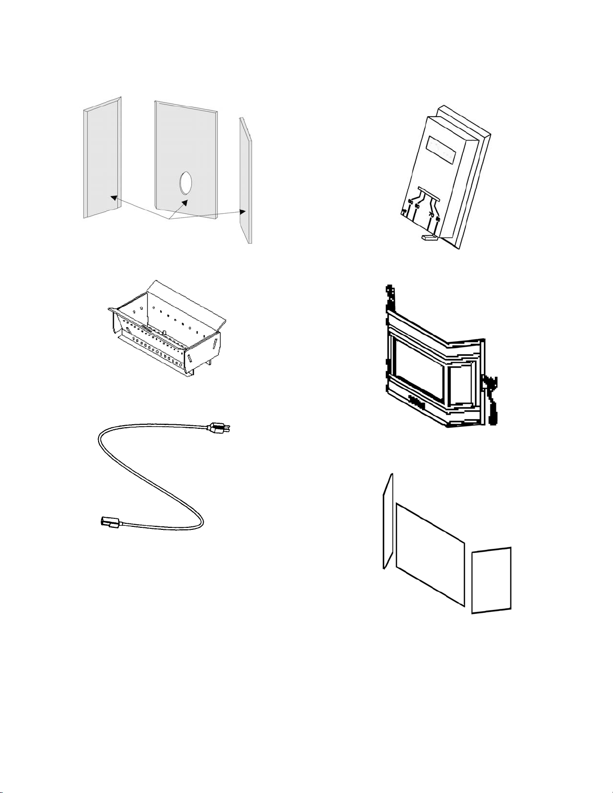
REPLACEMENT PART DIAGRAMS
www.PelletKing.com
Firebrick Kit
3 Piece Set
UltraGrate
TM
Kit
Wall Thermostat Kit
Door Assembly
Power Cord Kit
Glass
(Order each pc. separately. Gasket Included)
PAGE 40
Page 41

REPLACEMENT PART DIAGRAMS
www.PelletKing.com
Pressure Switch Kit
(hose not included)
Auger Motor
Auger Set Collar
Auger End Plate Gasket
Room Air Blower
Exhaust Blower
Control Board
Damper Rod
PAGE 41
Page 42

OPTIONAL ACCESSORIES LIST AND DIAGRAMS
www.PelletKing.com
Catalog # Model Description Stove Model
H0423 TKAIIT-G Trivet, Gold All
70K99 TSPK-B Touch-up Spray Paint Kit, Flat Metallic Black All
H0424 SKSAIIT Surround Kit, Small, 28 1/2” x 40 3/4”, Black Insert
H0425 SKMAIIT Surround Kit, Medium, 32” x 44”, Black Insert
H0426 SKLAIIT Surround Kit, Large, 36 x 48”, Black Insert
H0427 STKSAIIT-G Surround Trim Kit, Small, 28 1/2” x 40 3/4”, Gold Insert
H0428 STKMAIIT-G Surround Trim Kit, Medium, 32” x 44”, Gold Insert
H0429 STKLAIIT-G Surround Trim Kit, Large, 36 x 48”, Gold Insert
H0452 HEK-AIIT Hearth Extension Support Kit (for elevated hearths) Insert
H0430 DLS-AIIT Log Set All
Gold Trivet
(Cat. # H0423)
Surround Kits & Trim Kits
48" Large Trim (Cat. #H0429)
44" Medium Trim (Cat. #H0428)
40 ¾" Small Trim (Cat. #H0427)
Surround Kit Approx. Sizes:
Large: (Cat. #H0426)
36” (91.4cm) height
48” (121.9cm) width
Medium: (Cat. #H0425)
32” (81.3cm) height
44” (111.75cm) width
Small: (Cat. #H0424)
28 ½” (72.4cm) height
40 ¾” (103.5cm) width
28 ½"
Sm.
Tr.
32"
Med.
Tr.
36"
Lg.
Tr.
3 1/2" – 9"
Adjustable
Hearth
Support
Base w/
Trim Skirt
Log Set
(Cat. #H0430)
PAGE 42
Page 43

ADVANTAGE II-T C PELLET STOVE SAFETY LABEL
www.PelletKing.com
Note that your stove’s serial number is printed on the safety label, which is located near the inside of the hopper. Your
stove’s serial number is preceded by a “WH-”(Example WH-0000000).
PAGE 43
Page 44

ADVANTAGE II-T C: EPA LABEL & COLORADO COMPLIANCE LABEL
www.PelletKing.com
PAGE 44
Page 45

SIMPLE OPERATING INSTRUCTIONS LABEL
www.PelletKing.com
PAGE 45
Page 46

INSTALLATION TIPS
www.PelletKing.com
PAGE 46
Page 47

OWNERSHIP RECORDS
www.PelletKing.com
Dealer’s Name:
Dealer’s Address:
City: State: Zip Code:
Serial Number: Date of Purchase: Date Installed:
Notes:
SERVICE AND MAINTENANCE LOG
Service Service Service
Date Technician Description
PAGE 47
Page 48

www.PelletKing.com
1110 West Taft Avenue
Orange, CA 92865
 Loading...