

Page 1

iHarmony® Zoning System - Zone Sensor
(17A30)
Installation and Setup Guide
507826-01 6/2018
©
Lennox Industries Inc.
Dallas, Texas, USA
Page 2
Tables of Contents
Shipping and Packing List .................................... 2
Electrical Characteristics ...................................... 3
Dimensions ........................................................... 3
Unit Dimensions (H x W x D) .............................................. 3
Wall Plate Dimensions (H x W) ........................................... 3
Installation Guide .................................................. 3
Installation Considerations .................................................. 3
Unpacking Zone Sensor and Determining Best Location ... 4
Installing Zone Sensor ........................................................ 4
Zone Sensor Terminal Information ...................................... 6
Connecting Zone Sensor Wiring ......................................... 6
Install Zone Sensor to Backplate ........................................ 8
Setup Guide..........................................................8
Apply Power ........................................................................ 8
Menu > Advanced Settings ................................................. 8
Installer Checklist ...............................................12
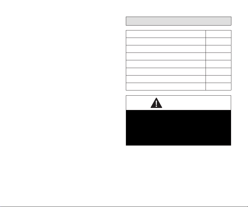
Shipping and Packing List
Item Quantity
Zone sensor with backplate attached 1
Wall plate 1
Mounting screws (M3.5x25mm self-tapping screws) 2
Wall anchors 2
Warranty sheet 1
Installation and setup guide 1
User guide 1
WARNING
Improper installation, adjustment, alteration, service or maintenance can cause property damage,
personal injury or loss of life.
Installation and service must be performed by a licensed professional HVAC installer (or equivalent)
or a service agency.
The 17A30 Zone Sensor can be used in systems
controlled by any Lennox communicating thermostat.
The 17A30 zone sensor can also be used in
combination with the 10C17 In-Zone thermostat.
2
Page 3
CAUTION
This is a 12VDC low-voltage zone sensor. Do not
install on voltages higher than 14VDC.
Electrical Characteristics
Dimensions
Unit Dimensions (H x W x D)
Dimensions: 3-5/16 x 4-5/16 x 7/8 in. (84 x 110 x
22mm)
Wall Plate Dimensions (H x W)
All values are at 77°F (25°C). This unit does employ
mis-wire circuit protection.
Table 1. Zone Sensor Power Requirements
Min Nom Max Unit
Input
Voltage
Input
Current
10 12 14 VDC
- 61.5 133 mA
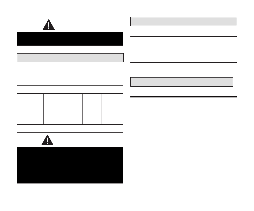
WARNING
Always turn off power at the main power source
by switching the circuit breaker to the OFF
position before installing or removing this zone
sensor.
All wiring must conform to local and national
building and electrical codes and ordinances.
Dimensions: 4-1/2” x 5-3/4” (114 x 146mm)
Installation Guide
installation ConsiDerations
The 17A30 zone sensor is a 12VDC low-voltage
device and requires a common wire to the damper
control module to operate.
• Shut off all power to system components before
installing zone sensor
• Make sure that all wiring conforms to local
and national building and electrical codes and
ordinances
• Never install the zone sensor on outside walls or
in direct sunlight
3
Page 4
UnPaCking Zone sensor anD Determining Best
loCation
This procedure is for either new or relocating a zone
sensor installations.
1. Unpack the zone sensor.
2. Select a location for the zone sensor about 5
feet (1.5 meters) above the oor in an area with
good air circulation at average temperature.
3. Do not install the zone sensor where it can be
affected by:
• Drafts or dead spots behind doors and in
corners
• Building entrances or automatic doors
• Heat generating equipment such as kitchen
appliances
• Hot or cold air from ducts
• Radiant heat from sun or appliances
• Concealed pipes and chimneys
• Non-heated (non-cooled) areas such as an
outside wall behind the zone sensor
installing Zone sensor
IMPORTANT
Installation uses 18 gauge thermostat wire with
a wire run length NOT TO EXCEED 197 feet (60
meters) between damper control module and any
one zone sensor.
Do not run wiring next to high voltage or high
voltage ballast.
Load from any zone sensor connection is 1 AMP
or less.
1. Run thermostat wiring from iHarmony damper
control module to location where zone sensor
will be installed.
2. Drill or make opening through wall for thermostat
wiring 3/4” x 3/4” (19mm x 19mm).
3. Pull about 3 inches (76mm) of thermostat
wire through the opening and removed outer
thermostat wire jacket. This will help in routing
the thermostat wiring to the proper zone sensor
terminals.
4. Seal the hole in the wall with a suitable material
to prevent drafts from entering the zone sensor
case. Not doing so could affect the zone
sensor’s internal temperature and humidity
sensors.
4
Page 5

5. Trim 1/4 inch (6 mm) insulation from end of each
Wall Plate (optional)
Zone Sensor Back Plate
Run thermostat wire
through openings
thermostat wire lead.
6. Use the provided wall plate as a template on
where to drill the mounting holes.
NOTE: Installation of wall plate is optional. Use
a eld-provided level to allow for proper
alignment.
(Use a level) Align Wall Plate
Use unit wall plate as template to mark desired
mounting hole locations on wall.
7. Drill 3/16” (5 mm) holes in wall for provided wall
anchors. Insert provided wall anchors into drilled
holes.
8. Remove back plate from main zone sensor
assembly using a at-head screw driver.
9. Route wiring from wall through center openings
on wall plate (use is optional) and back plate.
5
Page 6

10. Secure back plate and wall plate (optional) to
Wall Plate (optional)
Zone Sensor Back Plate
Screw
PWR D+ D- C
wall with the two provided mounting screws.
Zone sensor terminal information
ConneCting Zone sensor Wiring
Use “Table 2. Terminal Designations” on page
6for connecting the thermostat wiring to the
back plate terminals.
Table 2. Terminal Designations
Terminal Purpose
PWR Zone sensor power 12VDC input.
D+ Zone sensor data high.
D- Zone sensor data low.
C Zone sensor 12VDC return.
See “Figure 2. Connecting Zone Sensor to Damper Control Module”
on page 7.
Figure 1. Backplate
NOTE: Remember to seal the hole in the wall with
a suitable material to prevent drafts from
entering the zone sensor case. Not doing
so could affect the zone sensor’s internal
temperature and humidity sensors.
6
Page 7

SENSE 24VAC
PRESSURE SW
C SENSE
DATS
D+
PWR
D-
C
ZONE 5
D+
PWR
D-
C
ZONE 2/6
D+
PWR
D-
C
ZONE 3/7
D+
PWR
D-
C
ZONE 4/8
1 – 4
5 - 8
Zone Sensor
C
D-
D+
PWR
NOT USED
Unused wires
Single wire
to terminal “C”.
Damper Control Module
17A30 Zone Sensor
PWR D+ D- C
SENSE 24VAC
PRESSURE SW
C SENSE
DATS
D+
PWR
D-
C
ZONE 5
D+
PWR
D-
C
ZONE 2/6
D+
PWR
D-
C
ZONE 3/7
D+
PWR
D-
C
ZONE 4/8
1 – 4
5 - 8
Figure 2. Connecting Zone Sensor to Damper
Control Module
Figure 3. Communicating and Low Voltage
Connections
install Zone sensor to BaCkPlate
The zone sensor assembly simply snaps onto the
back plate. Once secure to the back plate apply
power to the system. The zone sensor should boot
up and go into the commissioning process.
Figure 4. Installing Zone Sensor
7
Page 8

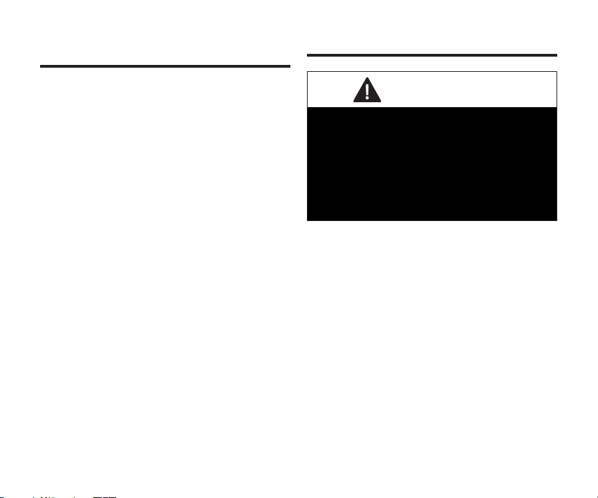
If power is applied and the zone sensor screen
zone number
zone 3
+
-
remains off, inspect and verify all wire connections.
Setup Guide
aPPly PoWer
After power is applied to the zone sensor for the
rst time it will display the Lennox® “splash screen”
and then the zone number selection screen. Set the
address using the plus/minus buttons. Selections
are 2, 3 or 4.
NOTE: Zone 1 is always the thermostat.
Figure 5. Zone Selection
CAUTION
When replacing a failed zone sensor, remember to
set the new zone sensor to the same address as
the one being replaced. Also, If an existing zone
sensor has failed and being replaced by a zone
sensor relocated from another zone in the home,
remember to set relocated zone sensor’s address
to match the one that has failed. Not doing so
could contribute to incorrect zone operations and
possible equipment damage.
menU > aDvanCeD settings
This represents the menu icon. Most
procedures will start with menu and with
directions to sub-menus.
Table 3 lists the settings that can be adjusted under
this menu selection
Table 3. Advanced Settings
Menu Selection Setting
Zone
Number
Reset
Restart Reboots the zone sensor.
Default value is 2. Minimum value is 2.
Maximum value is 4. Adjustment is made with
either the + or - selection tool..
Resets the zone sensor to factory default
settings. Select Conrm to reset all.
8
Page 9

Alert Codes
Error
Message
Code
Type
Condition and
Email Notication
Description
Table 4. Alert Codes
Thermostat Display
Text
System Action
Action to Clear /
Recovery Condition
542
543
544
545
Critical
Temperature Sensor
Error
Temperature Sensor
Error
Temperature Sensor
Error
Temperature Sensor
Error
Problem (Zoning
Control)
Problem (Zoning
Control)
Problem (Zoning
Control)
Problem (Zoning
Control)
Indoor temp is displayed
as “--” on the home
screen.
Anytime there is a zone
sensor temperature
sensor error or any
zone sensor loses
communication with the
damper control module,
the entire system will go
into central mode.
9
Error could be due to either a
temperature sensor error or lost
communication between zone
sensor and damper control module.
If problem is due to temperature
sensor issue, then zone sensor
will need to be replace. If sensor
auto corrects itself the alert will
be automatically cleared and
1
system will return to normal zone
inside
0
operations.
Error codes 542, 543, 544 and
545 could also be caused by lost
communication with the damper
control module. If this is the case,
most likely an error code 551 is
being displayed at the applicable
zone sensor.
Check wiring between damper
control module and the zone
sensor reporting error code 551.
NOTE: If error is due to lost
communication 551,
error notication 542,
543, 544 and 545 will
only be displayed at the
thermostat.
Page 10

Error
Code
Message
Type
Condition and
Email Notication
Description
Table 4. Alert Codes
Thermostat Display
Text
System Action
Action to Clear /
Recovery Condition
546 Critical
547 Critical
548 Critical
EEPROM error (Power
ON)
EEPROM error
(Operating)
Hum sensor error
(Without Humidier or
Dehumidier): sensor
reads out of range 0%
to 100%
Memory error
Memory error
Humidity sensor error
10
System will set itself to
energy save mode and
continue to operate.
System will operate in
normal mode operation
until power off.
This message indicates
humidity sensor has
malfunction.
Zone sensor will have to be
replaced..
Zone sensor will have to be
replaced.
Zone sensor will need to be
replaced or if sensor auto corrects
itself the alert will be automatically
cleared and system will return to
normal operation.
Page 11

Error
Code
Message
Type
Condition and
Email Notication
Description
551 Critical Lost communication
Table 4. Alert Codes
Thermostat Display
Text
Problem (Zoning
Control)
System Action
A pop-up display will
appear indicating
communication error.
Indoor temp is displayed
as “--” on the home
screen.
When any zone sensor
loses communication
with the damper control
module, the entire
system will go into
central mode.
1
inside
0
Action to Clear /
Recovery Condition
Once communication is
reestablished the device will return
to normal zone operations.
Any lost communication between
the zone sensor and damper
control module will result in the
applicable error code being
displayed 542, 543, 544 or 545 at
the thermostat.
Check wiring between damper
control module and the zone
sensor reporting error code 551.
11
Page 12

Installer Checklist
Table 5. Installation Checklist
Item Description Yes No
1 Is the zone sensor properly mounted to either a wall stud or wall? (Do not mount on exterior wall or near any
ventilation outputs, doorways or location that could be directly exposed to sunlight)
2 Are all terminals wiring properly connected and tight?
4 Have all the zone sensor features been explained to the homeowner?
5 Has user manual been given to homeowner?
6 Was the correct thermostat wiring gauge used?
7 Are unused thermostat wires (conductors) wired together to minimize electrical interference that could affect
electronic components in the zone sensor. (See “Figure 3. Communicating and Low Voltage Connections”
on page 7.)
8 Was the hole in the wall sealed with a suitable material to prevent drafts from entering the zone sensor case.
Not doing so could affect the zone sensor internal temperature sensor.
9 Did the address get set correctly during initial power up of the zone sensor?
10 When replacing an existing zone sensor did you set the address of the new or relocated zone sensor to
match the address of the zone sensor being replaced?
12
 Loading...