


INSTALLATION
OPERATING &
MAINTENANCE MANUAL
Comfair
HC/HT
ENGLISH
MARCH 04


CONTENTS
CONTENTS1
INTRODUCTION2
RECOMMENDATIONS2
FIRST PART: FOR THE INSTALLER
TRANSPORTATION, RECEIVING, HANDLING
Safety rules3
APPLIANCE DESCRIPTION
General technical data4-5
Main parts6
INSTALLATION
Recommendations for installation7
Fan coil installation7-8
Installation of the white pre-enamelled sheet metal panel (version 7)9
Installation of the white pre-enamelled sheet metal panel (version 2 and 3)10
Installation of the white lacquered wood panel11
WATER CONNECTIONS
Connection to the water mains12
Condensate water drainage12
ELECTRICAL CONNECTIONS
Recommendations
Connections to the terminal block: housing without control panel13
Connections to the terminal block: housing with control panel14
Changing the motor speeds of rotation14
TESTING14
TURNING THE COIL15
SECOND PART: FOR THE USER
USING THE APPLIANCE
Warnings16
Using the control panel17
CLEANING THE APPLIANCE
Cleaning the air filter18
Cleaning the housing and the control panel19
TROUBLESHOOTING20
DISMANTLING THE APPLIANCE20
INSTALLATION - OPERATING & MAINTENANCE MANUAL
Page 1

INTRODUCTION
This installation, operation and maintenance booklet should always accompany the fan coil for ready consultation by
the installer or user if necessary.
The appliance should be installed in compliance with the regulations in force in each country and according to the
manufacturer's or qualified installer's instructions.
The manufacturer cannot be held liable for any damage to property or injury to persons and animals caused by incorrect
installation of the appliance.
Only qualified persons should install the appliance and connect it to the mains electricity supply.
Before carrying out any work on the appliance, ensure that it is disconnected from the electricity supply.
Read this instruction booklet before installing the appliance.
RECOMMENDATIONS
The appliance is easy to use, but it is important to read this guide completely before using for the first time. This will
help you to:
- use the appliance in all safety;
- obtain best performance;
- avoid errors;
- respect the environment:
Do not allow children or unassisted handicapped persons to use the appliance.
Do not touch the appliance with wet parts of the body or if barefoot.
Do not tug, pull or twist electrical cables attached to the appliance, even when disconnected from the electricity supply.
Do not open the flaps giving access to the internal parts of the appliance without having first put the system on-off
switch to "off".
Do not introduce sharp pointed objects through the air intake and outlet grilles.
Do not leave packing material (cardboard, staples, plastic bags, etc.) within reach of children since they could be a
source of danger. Dispose of correctly.
Do not sit or climb on the appliance or rest any type of object on it.
Do not spray or throw water directly on the appliance.
Do not use the appliance in places with suspended dust/powder or in potentially explosive atmospheres, in very damp
environments or in the presence of oil in suspension or in particularly aggressive atmospheres.
Do not cover the appliance with objects or drapes that even partially obstruct the air flow.
The appliance works by electricity at mains voltage (230 Vac, 50 Hz). Always bear in mind that mains voltage is
potentially dangerous and any appliance connected to it should be used with caution. Before carrying out any work
on the appliance, disconnect it from the electricity supply (by pulling out the plug from the mains socket or isolating
the supply line by putting the on-off switch to off).
If the appliance is not to be used for long periods, make sure that the controls are in the position 0 (off). If the appliance
is not going to be used in winter when temperatures are near to freezing, drain the system and ensure that the appliance
heat exchanger has no water in it in order to prevent the formation of ice and consequent breakage.
To make the appliance inoperable, disconnect it totally from the electricity supply.
It is unsafe to alter or try to alter the characteristics of this product. Any tampering or alteration renders the warranty
null and void.
In the event of malfunction or failure, do not try to repair the appliance yourself; contact a qualified technician. Repairs
carried out by unqualified persons could cause damage or accidents.
Always keep the appliance clean. In particular clean the air filter periodically (at least once a month).
FAILURE TO COMPLY WITH THE ASSEMBLY INSTRUCTIONS GIVEN IN THIS
GUIDE RELIEVES LENNOX OF ALL AND ANY LIABILITY. INCORRECT
INSTALLATION COULD CAUSE MALFUNCTIONING OR FAILURE OF THE
APPLIANCE. IT COULD ALSO REPRESENT A HAZARD FOR THE USER.
!
INSTALLATION - OPERATING & MAINTENANCE MANUAL
Page 2
TRANSPORTATION, RECEIVING, HANDLING
The appliance is dispatched enclosed in special protective packaging, which should be kept intact until the appliance
is positioned in the final place of installation.
The appliance should be handled with extreme care, always keeping it in its original packaging.
One pallet may hold 11 fan coils model HC/HT 10-60 (9 in vertical + 2 in horizontal) or 9 fan coils model HC 70-90
(9 in vertical).
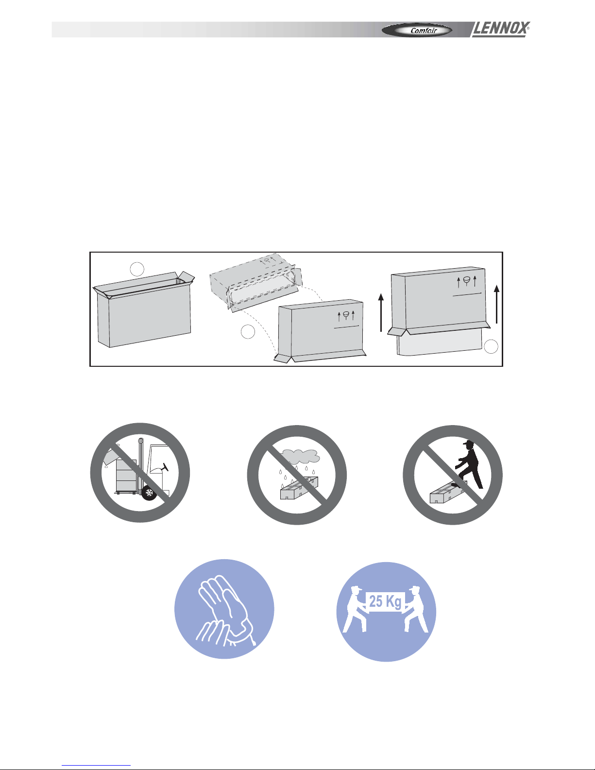
To take the appliance out of the packaging, proceed as follows (fig. 1):
1. Turn the fan coil box upside down and open the bottom.
2. Remove the polystyrene filling and keep it.
3. Keeping the bottom of the box open, turn the pack 180°, taking care that the contents are firmly held before resting
it gently on the ground. Lift off the packaging from the appliance.
SAFETY RULES
Secure packs during
transportation.
Do not expose to the
elements.
Do not tread on packs.
Protect hands with work gloves when
dismantling the appliance.
Work in PAIRS if the appliance weighs
more than 25 kg.
Fig. 01
1
2
3
INSTALLATION - OPERATING & MAINTENANCE MANUAL
Page 3

SERIE
WIND
GENERAL TECHNICAL DATA
147
Ø 20
200
274
137
337
67
39
109
103
53
without cabinet
220
225
200
Ø 20
147
374
124
268
253
41
107
101 52
220
225
with cabinet
3/4" G
1/2" G
1/2" G
3/4" G
L
H
25
130
30
M
D
C180 110
Fig. 02
APPLIANCE DESCRIPTION
MODEL HC10 HC20 HC30 HC40 HC50 HC60 HC70 HC80 HC90
No.
Rows No.
Fittings Ø
Rows No.
Fittings Ø
Ø mm
mm
mm
mm 660 860
mm 420 620
370 570
395 595
mm
mm
Kg 14 17 22 23 27 28 30 35 36
W 38 54 60 61 97 210 207
A 0,18 0,25 0,28 0,28 0,45 0,96 0,95
Electricity supply 230V/1/50 Hz
99
0,45
1.060 1.260
820 1.020
225
795 995 1.195
Depth with housing 220
460 565
1.460
1.220
(D)
1.170970770
585
321Fans
Auxiliary coil
Standard coil
3/4"
1
3
1/2"
20
480
Max. electric fan power
Max. electric fan current
Condensate drain fitting
Height with housing (H)
Width with housing
(M)
Net weight
Height without housing
Depth with housing (S)
(C)
MAIN PARTS
LOAD-BEARING STRUCTURE
Galvanised (8/10) sheet metal insulated even in those parts that are not in direct contact with the heat-transfer fluid.
Condensate collecting tray in insulated, galvanised sheet metal complete with fittings for condensate drainage. Sides
with knock-outs for fast fixing of accessories. Wall-mounting slots for easy fixing and levelling of appliance.
HEAT EXCHANGE COIL
Coils in copper piping expanded into aluminium fins in continuous block. Brass headers with female fittings (gas thread)
and easily accessible air valves. Water fittings positioned on the left (facing the appliance).
ELECTRIC FAN UNIT
Double inlet centrifugal fans with statically and dynamically balanced horizontally-oriented aluminium impellers.
Single-phase asynchronous electric motor with overload cutout. 6 speeds of rotation (3 connected). The motor is directly
coupled to the fans and cushioned with flexible mountings to ensure low noise.
Tab. 1
Model
10-60 Model
70-90
INSTALLATION - OPERATING & MAINTENANCE MANUAL
Page 4

136
3
3
121 233
26
12
Length of unit with cabinet ( C )
Length of recessed unit without motor (A)
12
109
Length of recessed unit with motor (B) Depth with cabinet 206
Depth without cabinet202
190
213
16
329 77
259 154
Height without cabinet 460
Height with cabinet 477
45 83
123 41
1/2"G
1/2"G
Fig. 02
6
2
GENERAL TECHNICAL DATA
2
APPLIANCE DESCRIPTION
MODEL HT100 HT200 HT300 HT400 HT600
Fan No, 1 1 1 1 1
Rows No, 2
Fittings Φ
Rows No,
Fittings Φ
Condensats drain fitting Φ
Height with housing mm
Height without housing mm
Width with the housing mm 760 760 960 1160 1360
Width without the housing without the motor (A) mm 640 640 840 1040 1240
Width without the housing with the motor (B) mm 740 740 940 1140 1340
Depth with the housing mm
Depth without the housing mm
Net Weight kg 14 16 21 26 30
Max. electric fan power W 29 29 36 39 50
Max. electric fan current A 0,14 0,14 0,17 0,17 0,23
Electrical supply 230V/1/50Hz
460
206
202
Auxiliary coil
1/2"
1
16
Standard coil
3
1/2"
480
MAIN PARTS
LOAD-BEARING STRUCTURE
Galvanised (8/10) sheet metal insulated even in those parts that are not in direct contact with the heat-transfer fluid.
Condensate collecting tray in insulated, galvanised sheet metal complete with fittings for condensate drainage. Sides
with knock-outs for fast fixing of accessories. Wall-mounting slots for easy fixing and levelling of appliance.
HEAT EXCHANGE COIL
Coils in copper piping expanded into aluminium fins in continuous block. Brass headers with female fittings (gas thread)
and easily accessible air valves. Water fittings positioned on the left (facing the appliance).
ELECTRIC FAN UNIT
Tangential fans with statically and dynamically balanced horizontally-oriented aluminium impellers.
Single-phase asynchronous electric motor with overload cutout.3 speeds of rotation . The motor is directly
coupled to the fans .
Tab. 1
Model
10-60 Model
70-90
INSTALLATION - OPERATING & MAINTENANCE MANUAL
Page 5
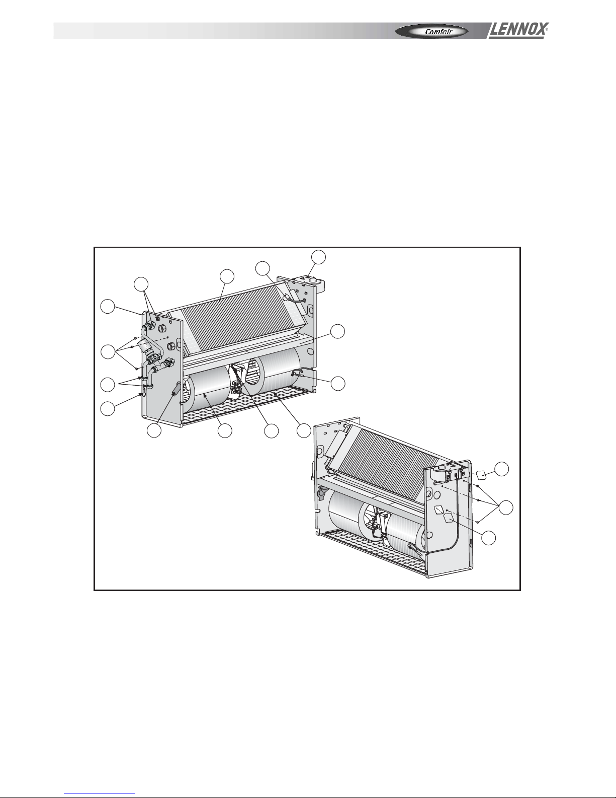
LEGEND
1 Air valve
2 Exchange coil
3 Minimum water temp. sensor
4 Control panel
5 Condensate collecting tray
6 Room thermostat sensor
7 Air filter
8 Electric motor
9 Fan
10 Condensate drain
11 Wall-mounting slots
12 Water connections
13 Coil fixing screws
14 Load-bearing structure
15 Knockouts
Fig. 03
MAIN PARTS
HOUSING
Modern, elegant design that blends in with any environment. Made in hot-galvanised sheet metal covered by a PVC
film to ensure high resistance to rust, corrosion, chemical agents, solvents and alcohols. Grilles and airflow louvers
in ABS as well as the control panel protective flap are to be found in the top part.
CONTROL PANEL
Protected by the flap, the control panel is housed in the side opposite the water fittings. It comprises a power switch
and the three-speed setting switch; it may include a room temperature thermostat (optional).
AIR FILTER
Easily removable, the filter is housed in the lower part of the appliance on the air intake prior to the fan. It comprises
a frame containing a filtering acrylic membrane that may be regenerated by vacuuming and washing.
2
15
13
15
13
2
5
6
4
3
1
7
8
9
10
11
12
14
INSTALLATION - OPERATING & MAINTENANCE MANUAL
Page 6

APPLIANCE INSTALLATION
RECOMMENDATIONS FOR INSTALLATION!
Before installing the appliance, ensure that:
1) the place of installation has sufficient space for carrying out installation as well as routine and extraordinary
maintenance work (see fig. 4);
2) there are no obstructions for air intake and delivery;
3) the water connections are of the sizes, in the position and spaced apart as required by the appliance (see
Dimensions);
4) the system pressure does not exceed 8 bar for the water versions;
5) the electricity supply corresponds to the data on the appliance rating plate and that there is a safety switch readily
accessible to the user to cut off the power supply whenever necessary.
6) the safety switch is in the OFF position so that there is no voltage on the appliance supply line.
!
Fig. 05
Fig. 06
Before installing the appliance, remove the housing (if present). Raise the flaps covering the control panel and the
water connections. Remove the two screws fixing the housing to the fan coil load-bearing structure. Gripping the
rear of the housing, remove it as shown in fig. 5 (N.B.: be careful of the lugs on the front part of the load-bearing
structure, as shown in fig. 10). Put the housing in the packing box to prevent it from being soiled or damaged (fig.
6).
Offer the appliance up to the required point of installation and mark, through the fixing holes, the points on the wall
where the holes should be drilled for the 4 screw anchors, as shown in fig. 7.
Fig. 07
Vertical version
Horizontal version
FAN COIL INSTALLATION
Fig. 04
9
0
1
5
0
140
1
130
INSTALLATION - OPERATING & MAINTENANCE MANUAL
Page 7

Remove the appliance from the point of installation, drill the holes where marked on the wall (see fig. 8) and insert
the screw anchors. Place the appliance against the wall and fix it by tightening the screws into the anchors (see fig.
9). Carry out the water and electrical connections as described in the relevant paragraphs. To replace the housing,
proceed according to instructions given below.
Fig. 08
Insert the lugs A into the relative slots B (fig. 11). Pivot the housing on its base until it is aligned with the wall.
Raise the flaps covering the control panel and the water connections and tighten the two fixing screws (fig. 5).
Fig. 10
Take the housing from the packing box. Standing in front of the fan coil, lift the housing, holding it by the sides, and
tilt it (fig. 10).
Fig. 11
Fig. 09
2
B
A
INSTALLATION - OPERATING & MAINTENANCE MANUAL
Page 8

2
INSTALLATION OF THE WHITE PRE-ENAMELLED SHEET METAL PANEL:
VERSION 7
Legend:
A. Panel in white pre-enamelled sheet metal
B. Outlet louvres
C. Intake grille with filter
N.B.: THE PROCEDURE IS IDENTICAL FOR THE CEILING-MOUNTED VERSIONS
Offer up the white pre-enamelled sheet metal panel to the built-in fan coil and fix it by tightening the screws in the
relative holes, as shown in figs. 14-15-16.
Ensure that the panel surface is perfectly parallel to the wall.
Insert the intake grille with filter (bottom) and the outlet louvres
(top), pressing them onto the relative catches (see fig. 17).
Fig. 17
Fig. 14
Fig. 15
Fig. 16
Fig. 12
Front view
A
B
C
Fig. 13
Rear view
70 70
A
INSTALLATION - OPERATING & MAINTENANCE MANUAL
Page 9

INSTALLATION OF THE WHITE PRE-ENAMELLED SHEET METAL PANEL:
VERSIONS 2 AND 3
Offer up the white pre-enamelled sheet metal panel to the built-in fan coil and fix it by tightening the screws in the
relative holes, as shown in figs. 20-21-22
Ensure that the panel surface is perfectly parallel to the wall.
Insert the intake grille with filter (bottom) and the outlet louvres
(top), pressing them onto the relative catches (see fig. 23).
Fig. 21
Fig. 22
Fig. 20
N.B.: THE PROCEDURE IS IDENTICAL FOR
THE CEILING-MOUNTED VERSIONS
Fig. 23
Legend:
A Panel in white pre-enamelled sheet metal
B Outlet louvres
C Intake grille with filter
Fig. 18
Frontal view
B
C
Fig. 19
Bottom view
70 70
A
A
INSTALLATION - OPERATING & MAINTENANCE MANUAL
Page 10

INSTALLATION OF THE WHITE LACQUERED WOOD PANEL
Legend:
A. Built-in fan coil
B. White lacquered wood panel
C. Outlet louvres
D. Intake grille with filter
Offer up the white lacquered wood panel, tilt it (fig. 25) and fix it with the relative catches to the load-bearing structure
of the built-in fan coil.
Ensure that the panel surface is perfectly parallel to the wall (fig. 26).
Use 2 screws to fix the panel to the fan coil (fig. 27). Insert the intake grille (with filter) and the outlet louvres into the
relative openings (see fig. 28).
Fig. 27
Fig. 28
Fig. 25
Fig. 26
N.B.: NOT AVAILABLE IN CEILING-MOUNTED VERSIONS!
Fig. 24
A
B
C
D
INSTALLATION - OPERATING & MAINTENANCE MANUAL
Page 11

!
CAUTION!
Always use a wrench and nose key for connection of the coil to the pipes (fig. 29). If the solenoid valve is
installed, suitably insulate the valve body with insulating material (fig. 30).
Connect the water inlet and outlet pipes, observing the indications given on the side of the appliance. Correctly
insulate the water supply pipes to prevent dripping during the cooling mode of operation. An shutoff valve should
be inserted on the water supply pipe and a balancing valve on the outlet pipe. The valve body and balancing valve
should also be properly insulated to prevent dripping. It is the installer's responsibility to insulate properly and the
manufacturer cannot be held liable for any insulation work.
N.B.: It is always advisable to install the solenoid valve.
In the heating mode of operation the solenoid valve reduces consumption because upon reaching the set
temperature the circulation of water is stopped to avoid wasting energy (the fan coil would otherwise
continue to heat like a radiator, even with the motor at a standstill).
In the cooling mode of operation the solenoid valve stops the circulation of water when the set temperature
is reached, thus stopping the internal exchanger from continuing to condense water with possible undesirable
dripping onto the floor. It also reduces chiller operation with consequent energy saving.
CONNECTION TO THE WATER MAINS
CONDENSATE WATER DRAINAGE
The condensate drain pipe should slope downwards by at least 3 cm/m and should not have ascending or throttled
sections in order to ensure a regular flow of water. It is advisable for a trap to be fitted. The condensate drain pipe
should be connected to a rainwater drainage system. Do not use sewage systems to avoid possible odours in the
event of evaporation of the water in the trap. Upon completion of work, check that the condensate flows out properly
by pouring water into the tray (see figs. 31 and 32). The condensate water drainage system should be fabricated
in a workmanlike manner and should be periodically checked.
The manufacturer cannot be held liable for any damage caused by dripping in the absence of a solenoid
valve or of periodic maintenance of the drainage system.
WATER CONNECTIONS
Fig. 30
Fig. 29
Fig. 32
3 cm/m
Fig. 31
5 mm
3 cm/m
INSTALLATION - OPERATING & MAINTENANCE MANUAL
Page 12

The cables should be sufficiently long so that they are
not permanently taut or create throttling or pressure
on metal parts (see fig. 33).
The power cables should be sufficiently long so that in the
event of accidental tugging the active wires are subjected
to stress before the earth wire.
Connect the earth wire to the relative terminal marked with
the symbol
Check the earth connection.
Comply with the safety regulations in force in the
country of installation.
ELECTRICAL CONNECTIONS
RECOMMENDATIONS
Before carrying out electrical connections, ensure that the electricity supply to the supply line has been cut off,
checking that the on-off switch is in the OFF position.
Only qualified electricians should carry out the electrical connections.
Check that the mains supply is single-phase 230 Vac/1/50 Hz (± 10%).
Operating the appliance with voltages outside the above limits could cause malfunction and renders the warranty
null and void.
The fan coil power supply line should be fitted with at least a switch isolator in conformity with European standard
EN60947-3.
Make sure that the electrical system is suitable for providing not only the working current required by the appliance,
but also the necessary current for powering household and other electrical appliances already in use. Any electrical
and mechanical alterations or tampering render the warranty null and void.
The motor and accessories power cables in channels or ducts should remain inside the same until they are inside
the appliances.
!
CONNECTIONS TO THE TERMINAL BLOCKS
Models without control panel
The electrical connections should be made to the terminal block on the side of the appliance. Each terminal is
identified by the label to be found on the terminal block.
Fig. 33
Tc
G/V
T
Fig. 34
I
II
III
M
III
II
I
COMMON
COMMON (WINTER)
COMMON (SUMMER)
INSTALLATION - OPERATING & MAINTENANCE MANUAL
Page 13

3
Models with control panel
The electrical connections should be made directly to the control panel, as shown by the relative wiring diagram. If
the control panel has an electronic temperature sensor (NTC), this sensor will be powered by mains voltage (230Vac/1/50
Hz) and is therefore provided with double insulation.
CAUTION!
FAILURE TO COMPLY WITH THE INDICATED CONNECTIONS MAY CAUSE
MOTOR BURNOUT!
!
CHANGING THE MOTOR SPEEDS OF ROTATION
The fan coil motor has 6 speed settings, 3 of which are connected in the factory (red, blue and black wires connected
to the motor auto-transformer). To use other speeds than those wired up in the factory, the red (minimum), blue
(medium) and black (maximum) wires may be connected onto 3 of the 6 numbered terminals (16), taking into account
that the speeds follow a sequence as shown in fig. 35.
!
* CAUTION! UNDER NO CIRCUMSTANCES SHOULD THE CONNECTIONS TO THE TERMINALS
L, M, M BE CHANGED!
TESTING THE FAN COIL
Upon completion of installation, scrupulously check both the water and the electrical connections before switching on
the appliance.
Before mounting the housing (if present), fill the system,
bring it up to pressure and bleed. Make the water circulate
and check for leaks. Check correct operation of the fan
coil at the 3 speeds, of the solenoid valves and of the
minimum temperature thermostat (if installed).
The housing is covered by a protective film: remove it
before fixing the housing to the appliance.
Remount the housing (if present), otherwise the customer
has the responsibility of concealing the appliance.
CAUTION!
Protect the appliance with a cardboard box if
building works are still being carried out (Fig.
36).
!
Fig. 36
Fig. 35
Common
Motor (*)
Motor (*)
Red
Blue
Black
INSTALLATION - OPERATING & MAINTENANCE MANUAL
Page 14

TURNING THE COIL
CAUTION!
The fan may reach the speed of 1,000 rpm. Do not insert objects
or hands into the electric fan. The motor becomes hot during
operation; wait for it to cool before touching it.
During the heating mode of operation the exchanger and the
connecting pipes may become very hot (80°C). Wait for the exchanger
to cool before touching it or protect hands with suitable gloves.
The heat exchange water coils are suitable for working up to
a maximum pressure of 8 bar.
To turn the coil, proceed as follows:
!
0°
60°
Fig. 37
P=8
bar max
0°
60°
Fig. 38
1. Remove the housing (if present).
2. Disconnect the terminal block or the control panel (2), if present, from the side of the appliance.
3. Remove the condensate collecting tray in horizontal models or the galvanised panels in vertical models (4).
4. Remove the coil fixing screws (5).
5. Take out the coil (1), being careful not to be cut by the fins and not to damage them.
6. Remove the knockouts (6) on the opposite side of the fan coil (using a screwdriver), to allow the coil connections
to pass through.
7. Position the coil, turning it without tipping it upside down, so that the fittings are in line with the holes left by the
knockouts.
8. Fix the coil using the previously removed screws (5).
9. Shift the control panel (2), if present, or the terminal block (fixing it to the side opposite the water fittings), the motor
and sensor cables (3), if present, fixing them with their grips. Ensure that the cables pass through the hole in the
side of the appliance, protecting them with the relative grommet. If it proves easier to carry out this operation by
separating the wires from the terminal blocks, mark the positions of the wires to avoid making mistakes when
reconnecting.
10. Reconnect the wires to the relative terminal blocks or control panel (2), taking care that they are correctly positioned.
11. Replace the condensate collecting tray (4) in horizontal models or the galvanised panels in vertical models.
12. Remount the housing (if present).
1
4
3
2
2
5
6
5
INSTALLATION - OPERATING & MAINTENANCE MANUAL
Page 15

USING THE APPLIANCE
WARNINGS!
This appliance should only be used by adults. Make sure that children do not touch the controls or play with the
appliance.
This appliance has been designed for use as a heating and cooling appliance in rooms that are clean and frequented
by persons (with normal pollution).
Avoid using for any other purpose.
This appliance should not be used in places with suspended dust/powder or in potentially explosive atmospheres, in
very damp environments or in the presence of oil in suspension or in particularly aggressive atmospheres.
Do not allow children or unassisted handicapped persons to use the appliance.
Do not touch the appliance with wet parts of the body or if barefoot.
Do not tug, pull or twist electrical cables attached to the appliance, even when disconnected from the electricity supply.
Do not open the flaps giving access to the internal parts of the appliance without having first put the system on-off
switch to "off".
Do not introduce sharp pointed objects through the air intake and outlet grilles.
Do not leave packing material (boards, staples, plastic bags, etc.) within reach of children since they could be a source
of danger. Dispose of correctly.
Do not sit or climb on the appliance or rest any type of object on it.
Do not spray or throw water directly on the appliance.
Do not use the appliance in places with suspended dust/powder or in potentially explosive atmospheres, in very damp
environments or in the presence of oil in suspension or in particularly aggressive atmospheres.
Do not cover the appliance with objects or drapes that even partially obstruct the air flow.
The appliance works by electricity at mains voltage (230 Vac, 50 Hz). Always bear in mind that mains voltage is
potentially dangerous and any appliance connected to it should be used with caution. Before carrying out any work
on the appliance, disconnect it from the electricity supply (by pulling out the plug from the mains socket or isolating
the supply line by putting the on-off switch to off).
If the appliance is not be used for long periods, make sure that the controls are in the position 0 (off). If the appliance
is not going to be used in winter when temperatures are near to freezing, drain the system and ensure that the appliance
heat exchanger has no water in it in order to prevent the formation of ice and consequent breakage.
To make the appliance inoperable, disconnect it totally from the electricity supply.
!
INSTALLATION - OPERATING & MAINTENANCE MANUAL
Page 16

USING THE APPLIANCE WITH CONTROL PANEL
If the appliance has a built-in control panel, raise the flap and proceed as follows.
Heating mode
Put the season selector switch from the off position ( ) to the winter position ( ).
The fan starts.
In models with minimum temperature thermostat (optional), the fan starts when the internal heat exchanger is sufficiently
hot. If the water is not hot enough, the fan does not start.
Cooling mode
Put the season selector switch from the off position ( ) to the summer position ( ).
The fan starts immediately.
Selecting the fan speed
Put the selector switch to the required speed. The higher the speed the quicker the room will be heated/cooled, although
appliance operation will be noisier (fig. 40).
Automatic temperature adjustment (for control panel with built-in thermostat)
This control panel has a built-in temperature sensor, which measures the room air temperature. This information is
used for the automatic control of the fan or introduction of water into the internal exchanger through the solenoid valve
(optional). The appliance thus keeps the room at the temperature set by the user.
The room temperature may be set approx. between 10°C and 30°C. If the appliance does not have a built-in
control panel, but is controlled by a wall-mounted thermostat, refer to the thermostat instructions for use.
CONTROL PANEL WITH THERMOSTAT
BASIC CONTROL PANEL
Fig. 39
!
Fig. 41
Turn the knob towards the symbol +
to raise the temperature
Turn the knob towards the symbol -
to lower the temperature
Minimum speed Medium speed Maximum speed
Fig. 40
INSTALLATION - OPERATING & MAINTENANCE MANUAL
Page 17

CLEANING AND MAINTENANCE
The appliance requires no periodic maintenance. Simple checks by the user to keep it in perfect working order are,
however, necessary.
CAUTION! Before carrying out any cleaning or maintenance work, disconnect the
appliance from the
mains electricity supply!
CLEANING THE AIR FILTER
The appliance is fitted with an air filter on the fan inlet. During normal operation the filter withholds impurities in the
air.
The filter should be cleaned periodically to keep its filtering properties and the airflow to the fan unchanged.
It is advisable to clean the filter at least once a month, proceeding as follows.
1. Take out the filter.
2. Place the filter on a flat, dry surface and remove the accumulated dust with a vacuum cleaner.
3. Wash the filter with water and detergent (no solvents).
4. Leave the filter to dry in a ventilated place in the sun.
5. Replace the filter when it is perfectly dry.
Clean the filter at the beginning and end of every season.
!
Fig. 43
Description fig. 42
Cleaning of the filter for the lower intake version
Description fig. 43
Cleaning of the filter for the front intake version.
N.B.: The procedure for ceiling-mounted horizontal versions is the same.
Fig. 42
W
A
T
E
R
+
D
E
T
E
R
G
E
N
T
W
A
T
E
R
+
D
E
T
E
R
G
E
N
T
INSTALLATION - OPERATING & MAINTENANCE MANUAL
Page 18

2
CLEANING AND MAINTENANCE
CAUTION! Before carrying out any cleaning or maintenance work, disconnect the appliance
from the mains electricity supply!
Under no circumstances use water for cleaning!
CLEANING THE HOUSING AND THE CONTROL PANEL
To clean the housing, use a dry soft cloth to avoid scratching the enamel.
To clean the control panel and the air outlet louvres, use a vacuum cleaner fitted with a soft dusting tool
or use a separate brush.
Delicately clean the louvres and the controls by removing dust from the cracks and corners. Under no
circumstances use water.
!
Fig. 44
20
INSTALLATION - OPERATING & MAINTENANCE MANUAL
Page 19

R
U
B
B
I
S
H
W
A
S
T
E
DISMANTLING THE APPLIANCE
This appliance is made to last for many years. Qualified
personnel are needed to dismantle it in all safety. The first
operation to be carried out before dismantling the appliance
is to disconnect it totally from the electricity supply.
This appliance has been made using recyclable materials
(copper, aluminium, brass, plastic) assembled by screws
and push-fits to make separation of the parts easy.
Contact a firm specialised in differentiated waste disposal;
it is the only way to be certain of correct recycling and
thereby contribute to protection of the environment.
TROUBLESHOOTING
Tab. 2
Power failure.
Switch in position 0.
Water in the system not hot
enough.
Clogged filter.
No hot water in the system.
Incorrectly positioned hot/cold
switch.
No cold water in the system.
Incorrectly regulated thermostat.
Air in the pipes.
Blocked condensate drain.
Check the on-off switch.
Change position on the control panel.
Check that the outlet temperature
is above 40°C.
Clean the filter.
Check that the boiler and
circulating pump are working.
Check that the switch is on
for heating and for cooling.
Check that the chiller and the
circulating pump are working.
Turn the thermostat knob (if
installed) left/right
Bleed by loosening the valve at
the heat exchanger inlet.
Switch off the appliance and
contact the installer to check
condensate drainage.
EFFECT POSSIBLE CAUSE
POSSIBLE REMEDY
Little outflowing air.
The appliance does not cool.
Water on the floor during cooling.
The fan does not turn.
The appliance does not heat.
The appliance heats/cools
very little.
INSTALLATION - OPERATING & MAINTENANCE MANUAL
Page 20


www.lennoxeurope.com
LENNOX DEUTSCHLAND GmbH
tel. : + 49 69 42 09 79 0
fax : + 49 69 42 09 79 40
e-mail : info.de@lennoxdeutschland.com
LENNOX INDUSTRIES LTD
tel. : + 44 1604 599400
fax : + 44 1604 594200
e-mail : marketing@lennoxind.com
LENNOX BENELUX N.V./S.A.
tel. : + 32 3 633 30 45
fax : + 32 3 633 00 89
e-mail : info.be@lennoxbenelux.com
LENNOX REFAC S.A.
tél. : + 34 902 400 405
fax : + 34 91 542 84 04
e-mail : marketing@lennox-refac.com
LENNOX FRANCE
tel. : + 33 4 72 23 20 20
fax : + 33 4 78 20 07 76
e-mail : accueil@lennoxfrance.com
LENNOX BENELUX B.V.
tel. : + 31 33 2471 800
fax : + 31 33 2459 220
e-mail : info@lennoxbenelux.com
LENNOX POLSKA Sp. z o. o.
tel. : + 48 22 832 26 61
fax : + 48 22 832 26 62
e-mail : lennoxpolska@inetia.pl
LENNOX CLIMATIZAÇAO LDA.
tel. : +351 22 998 33 70
fax : +351 22 998 33 79
e-mail : marketing@lennoxportugal.com
JANKA RADOTIN AS
tel. : + 420 2 510 88 111
fax : + 420 2 579 10 393
e-mail : janka@janka.cz
LENNOX DISTRIBUTION MOSCOW
tel. : + 7 095 246 07 46
fax : + 7 502 933 29 55
e-mail :lennox.dist.moscow@mtu-net.ru
LENNOX SLOVAKIA
tel. : + 421 7 44 87 19 27
fax : + 421 7 44 88 64 72
LENNOX DISTRIBUTION KIEV
tel. : + 380 44
461 87 75
fax : + 380 44
461 87 75
e-mail :
lennoxua@i.kiev.ua
LENNOX DISTRIBUTION
tel. : + 33 4 72 23 20 14
fax : + 33 4 72 23 20 28
e-mail : marketing@lennoxdist.com
ALLEMAGNE :
ANGLETERRE,
IRLANDE :
BELGIQUE :
ESPAGNE :
FRANCE :
PAYS-BAS :
POLOGNE :
PORTUGAL :
REPUBLIQUE TCHEQUE :
RUSSIE :
SLOVAQUIE :
UKRAINE :
AUTRES PAYS EUROPEENS :
AFRIQUE,
MOYEN-ORIENT :
HC/HT_IOM-03-04-E
 Loading...