

Lennox HSXA19, HSXA19-038, HSXA19-036, HSXA19-024, HSXA19 048 Installation Instructions Manual
...
Page 1
504,919M
*P504919M*
04/04
*2P0404*
©2004 Lennox Industries Inc.
Dallas, Texas
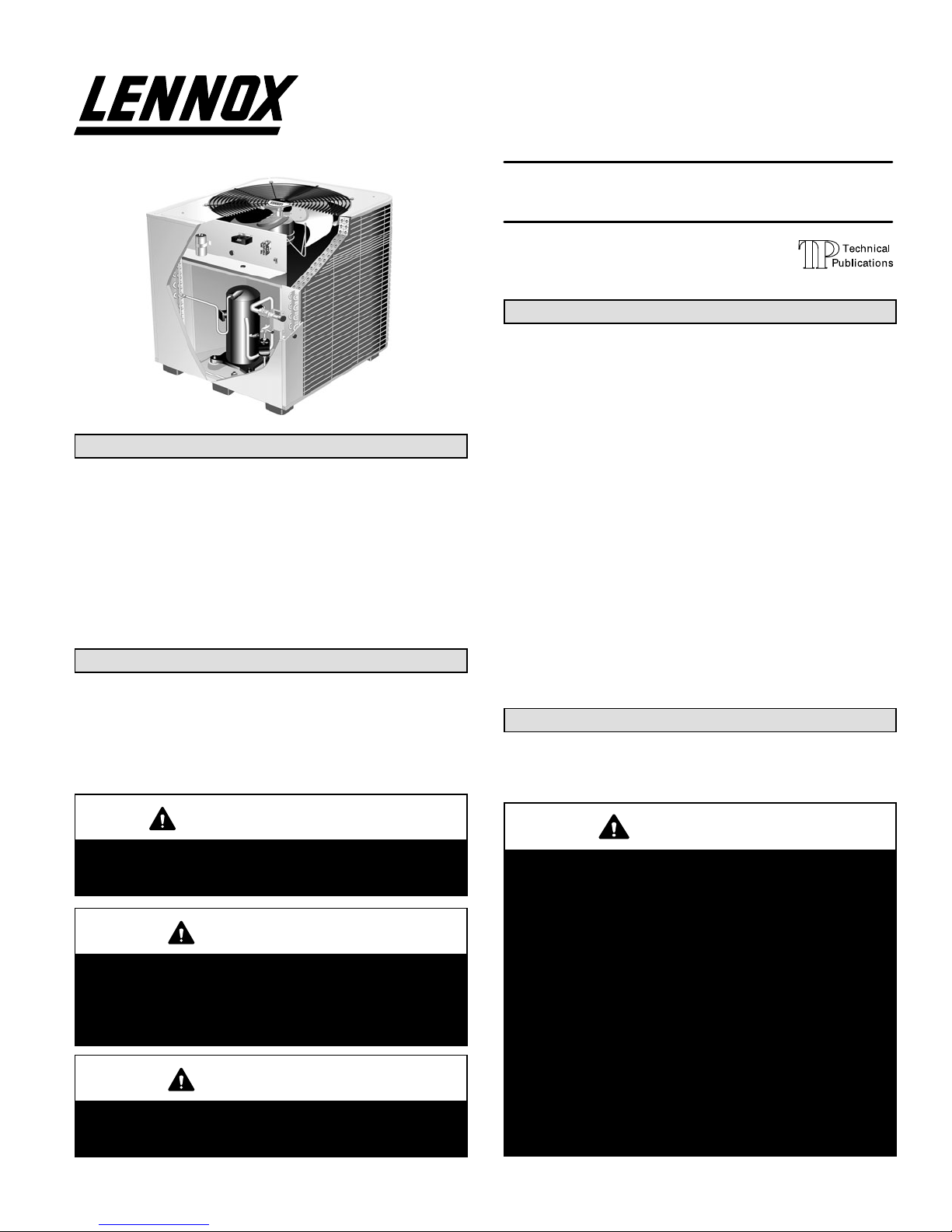
HSXA19 Outdoor Unit
Two−stage HSXA19 outdoor units use R410A which is an
ozone friendly HFC refrigerant. This unit must be installed
with a matching indoor coil and line set as outlined in the
Lennox Engineering Handbook. Dave Lennox Signature
Collection HSXA19 outdoor units are designed for use in expansion valve systems (TXV) only. They are not designed to
be used with other refrigerant flow control devices. The Lennox Engineering Handbook lists a TXV kit that must be ordered separately.
Shipping & Packing List
1 − Assembled HSXA19 outdoor unit
2 − Grommets (liquid and vapor line)
1 − Bushing (for low voltage wiring)
Check equipment for shipping damage. If you find any
damage, immediately contact the last carrier.
CAUTION
Danger of sharp metallic edges. Can cause injury.
Take care when servicing unit to avoid accidental
contact with sharp edges.
WARNING
Improper installation, adjustment, alteration, service
or maintenance can cause property damage, personal injury or loss of life. Installation and service must
be performed by a qualified installer or service
agency.
IMPORTANT
This unit must be matched with an indoor coil as
specified in Lennox’ Engineering Handbook. Coils
previously charged with HCFC−22 must be flushed.
INSTALLATION
INSTRUCTIONS
HSXA19 SERIES UNITS
CONDENSING UNITS
504,919M
04/04
Supersedes 03/04
Table of Contents
HSXA19 Outdoor Unit 1. . . . . . . . . . . . . . . . . . . . . . . . . .
Shipping & Packing List 1. . . . . . . . . . . . . . . . . . . . . . . . .
General Information 1. . . . . . . . . . . . . . . . . . . . . . . . . . . .
Unit Dimensions 2. . . . . . . . . . . . . . . . . . . . . . . . . . . . . . .
Parts Arrangement 3. . . . . . . . . . . . . . . . . . . . . . . . . . . . .
Setting The Unit 3. . . . . . . . . . . . . . . . . . . . . . . . . . . . . . . .
Electrical 4. . . . . . . . . . . . . . . . . . . . . . . . . . . . . . . . . . . . . .
Refrigerant Piping 7. . . . . . . . . . . . . . . . . . . . . . . . . . . . . .
Refrigerant Metering Device 11. . . . . . . . . . . . . . . . . . . .
Flushing Existing Line Set & Indoor Coil 11. . . . . . . . . .
Manifold Gauge Set 13. . . . . . . . . . . . . . . . . . . . . . . . . . .
Service Valves 14. . . . . . . . . . . . . . . . . . . . . . . . . . . . . . . .
Leak Testing 15. . . . . . . . . . . . . . . . . . . . . . . . . . . . . . . . . .
Evacuation 15. . . . . . . . . . . . . . . . . . . . . . . . . . . . . . . . . . .
Start−Up 16. . . . . . . . . . . . . . . . . . . . . . . . . . . . . . . . . . . . . .
Charging 16. . . . . . . . . . . . . . . . . . . . . . . . . . . . . . . . . . . . .
System Operation 21. . . . . . . . . . . . . . . . . . . . . . . . . . . . .
Maintenance 23. . . . . . . . . . . . . . . . . . . . . . . . . . . . . . . . . .
Optional Accessories 23. . . . . . . . . . . . . . . . . . . . . . . . . .
Homeowner Information 23. . . . . . . . . . . . . . . . . . . . . . . .
Check Points 24. . . . . . . . . . . . . . . . . . . . . . . . . . . . . . . . .
Retain These Instructions
For Future Reference
General Information
These instructions are intended as a general guide and do
not supersede local codes in any way. Consult authorities
who have jurisdiction before installation.
WARNING
This product and/or the indoor unit it is matched with
may contain fiberglass wool.
Disturbing the insulation during installation, maintenance, or repair will expose you to fiberglass wool
dust. Breathing this may cause lung cancer. (Fiberglass wool is known to the State of California to
cause cancer.)
Fiberglass wool may also cause respiratory, skin,
and eye irritation.
To reduce exposure to this substance or for further
information, consult material safety data sheets
available from address shown below, or contact your
supervisor.
Lennox Industries Inc.
P.O. Box 799900
Dallas, TX 75379−9900
Litho U.S.A.
Page 2
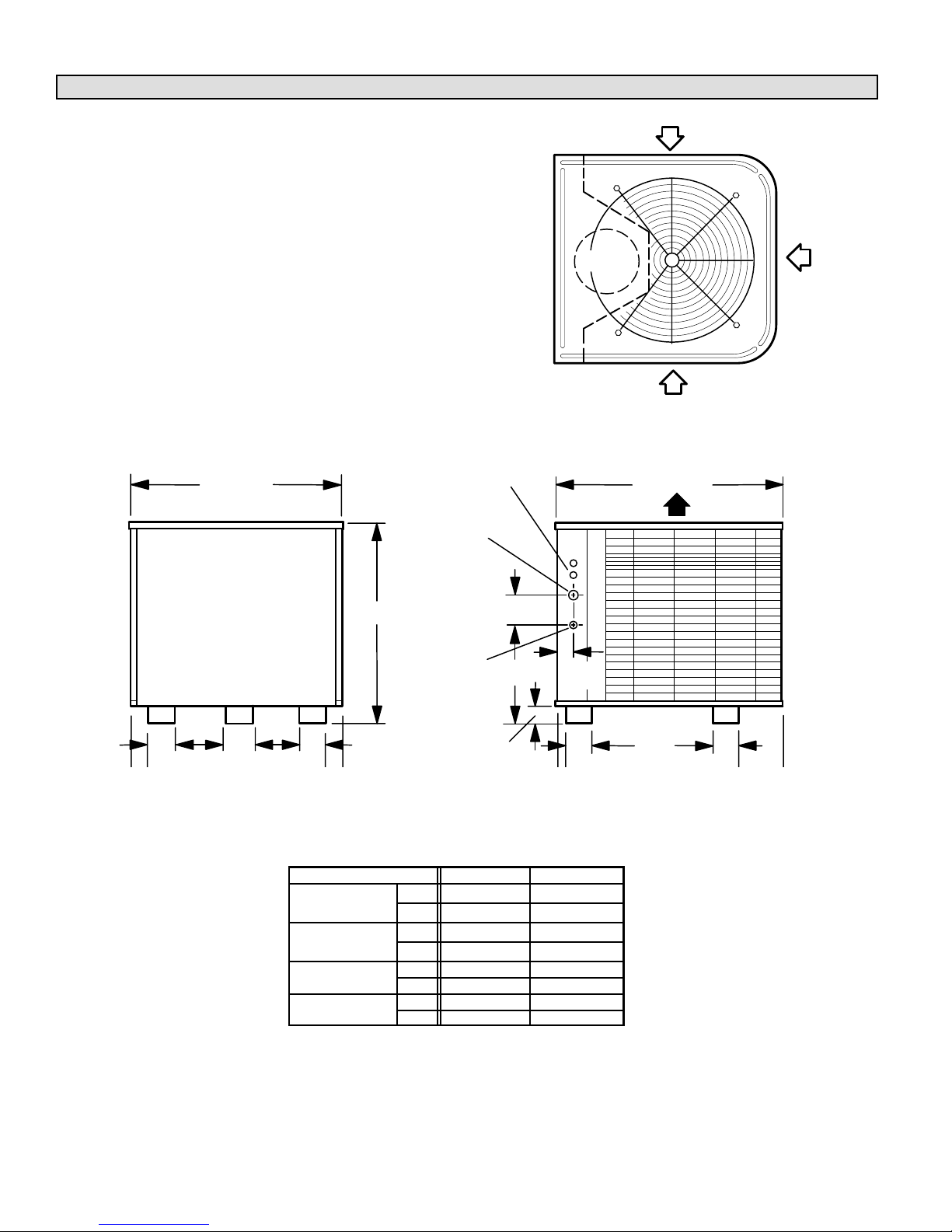
Unit Dimensions – Inches (mm)
ELECTRICAL
INLETS
SUCTION LINE
INLET
LIQUID
LINE INLET
DISCHARGE AIR
INLET
AIR
COMPRESSOR
B
TOP VIEW
4-1/2 (114)
2-3/4 (70)
4
A
4
2-9/16
(65)
AIRINLET
AIRINLET
3-1/8
(79)
3-1/8
(79)
3-1/8
(79)
32-1/8 (816) 34-1/16 (865)
18-5/8
(473)
9-1/8
(232)
9-1/8
(232)
Model No.
A B
HSXA19-024
in. 30-7/8 32-1/8
HSXA19-036
mm 784 816
in. 44−7/8 32−1/8
HSXA19-038
mm 1140 816
in. 34-7/8 13−3/4
HSXA19-048
mm 886 349
in. 40-7/8 19−3/4
HSXA19-060
mm 1038 502
Page 3
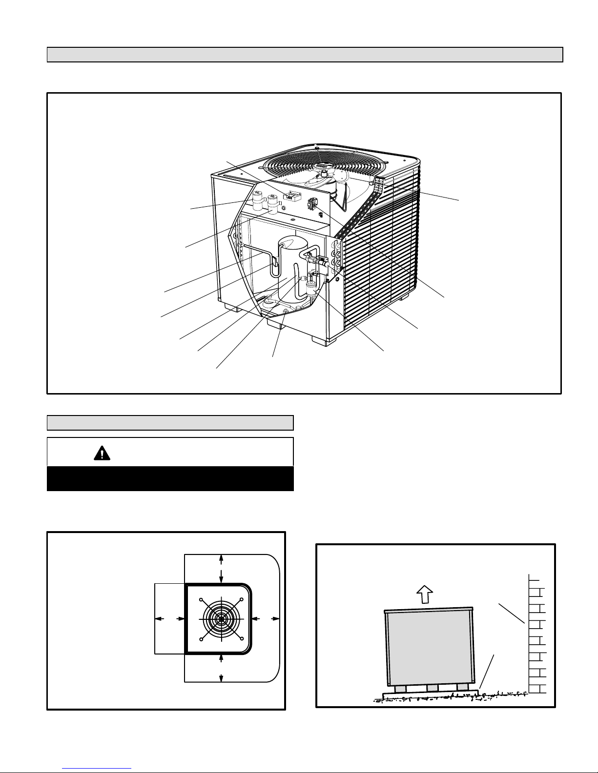
Parts Arrangement
Figure 1
outdoor fan
(variable speed
on HSXA19−038)
run capacitor
contactor
vapor valve and
gauge port
compressor terminal plug
discharge line
vapor line
two−stage compressor
system
operation monitor
low pressure switch
high pressure switch
filter drier
start capacitor
(HSXA19−024)
Setting the Unit
CAUTION
In order to avoid injury, take proper precaution when
lifting heavy objects.
Refer to unit dimensions for sizing mounting slab, platforms or supports. Refer to figure 2 for installation clearances.
30"
(762 mm)
as noted
Installation Clearances
Figure 2
NOTE − A service access
clearance of 30" (762 mm)
must be maintained in front
of the service access panel.
Clearance to one side must
be 36" (914 mm). Clearance
to one of the remaining two
sides may be 12" (304 mm)
and the final side may be 6"
(152 mm).
NOTE − A clearance of 24" (610 mm)
must be maintained between two units.
NOTE − 48" (1219 mm) clearance required on top
of unit. Maximum soffit overhang is 36" (914 mm).
as
noted
as
noted
A − Slab Mounting
When you install the unit at grade level, the top of the slab
should be high enough above the grade so that water from
higher ground will not collect around the unit. See figure 3.
Slab should have a slope tolerance away from the building
of 2 degrees or 2 inches per 5 feet (51 mm per 1.5 m). Refer
to the next section (roof mounting) for barrier construction if
the unit must face prevailing winter winds.
2 degrees or
2 in. per 5 foot
(51 mm per 1.5 m)
slope tolerance away
from building structure
Slab Mounting
ground level
mounting
slab
building
structure
discharge air
Figure 3
Page 4
B − Roof Mounting
Install unit at a minimum of 4 inches above surface of the
roof. Care must be taken to ensure weight of unit is properly
distributed over roof joists and rafters. Either redwood or
steel supports are recommended.
Electrical
In the U.S.A., wiring must conform with current local codes
and the current National Electric Code (NEC). In Canada,
wiring must conform with current local codes and the current
Canadian Electrical Code (CEC).
Refer to the furnace or blower coil installation instructions
for additional wiring application diagrams and refer to unit
nameplate for minimum circuit ampacity and maximum
overcurrent protection size.
WARNING
Electric shock hazard.
May cause injury or death.
Line voltage is present at all components when unit is not in operation on
units with single pole contactors.
Disconnect all remote electric power
supplies before opening this panel.
Unit may have multiple power supplies.
WARNING
Unit must be grounded in accordance with national
and local codes. Electric Shock Hazard. Can cause
injury or death.
1 − Install line voltage power supply to unit from a properly
sized disconnect switch.
2 − Ground unit at unit disconnect switch or to an earth
ground.
NOTE − Connect conduit to the unit using a proper
conduit fitting.
NOTE − Units are approved for use only with copper
conductors.
24V, Class II circuit connections are made in the low
voltage junction box. Refer to appropriate figure for
field wiring. See figure 4 for field wiring. See figures 5
and 6 for typical wiring.
NOTE − A complete unit wiring diagram is located in
side the unit control box cover.
3 − Install room thermostat (ordered separately) on an in-
side wall approximately in the center of the conditioned
area and 5 feet (1.5 m) from the floor. It should not be
installed on an outside wall or where it can be affected
by sunlight, drafts or vibrations.
4 − Install low voltage wiring from outdoor to indoor unit
and from thermostat to indoor unit.
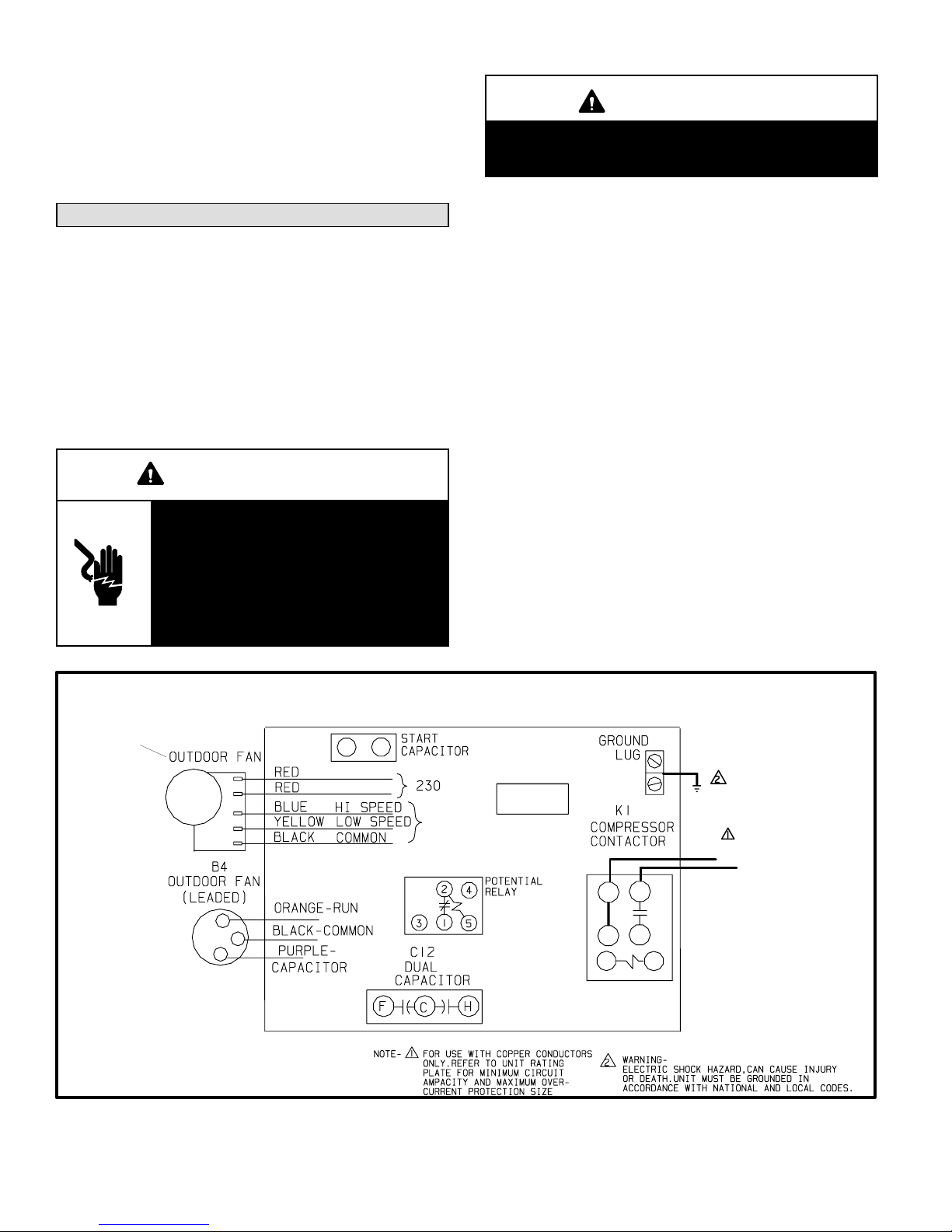
HSXA19 Outdoor Unit
Field Wiring Diagram
Figure 4
24V
variable speed
motor on −038
model only
208/230/60/1
SYSTEM
OPERATION
MONITOR
L2
L1
*
*−024 Unit
*
Page 5
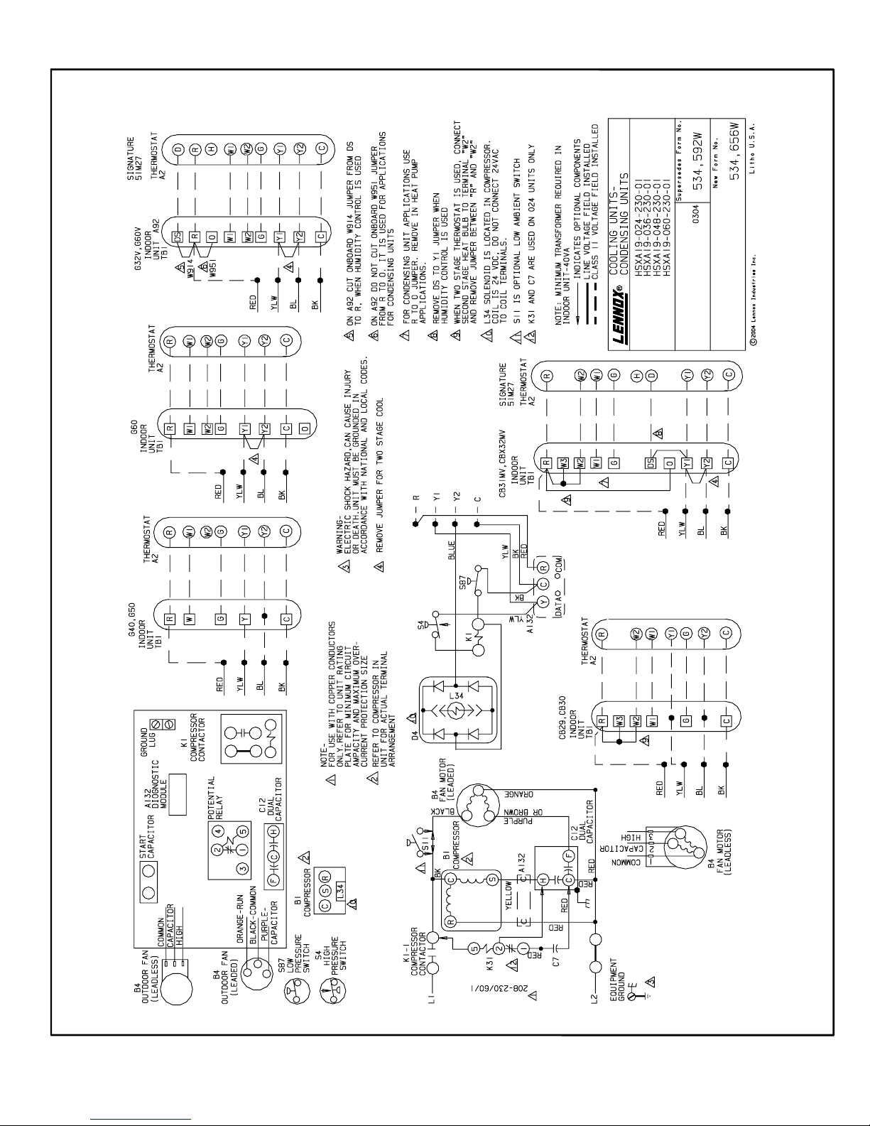
HSXA19−024, −036, −048, and −060 Wiring Diagram
Figure 5
Page 6
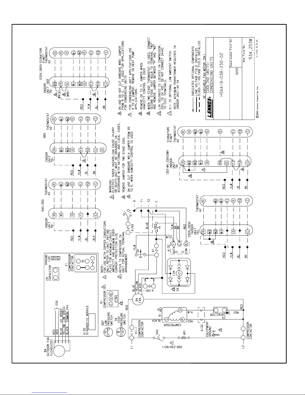
HSXA19−038 Wiring Diagram
Figure 6
Page 7
Refrigerant Piping
If the HSXA19 unit is being installed with a new indoor coil
and line set, the plumbing connections should be made as
outlined in this section. If an existing line set and/or indoor
coil is going to be used to complete the HSXA19 system,
refer to the following section which includes flushing procedures.
Field refrigerant piping consists of liquid and vapor lines
from the outdoor unit (sweat connections) to the indoor coil
(flare or sweat connections). Use Lennox L15 (sweat, nonflare) series line sets as shown in table 1 or use field-fabricated refrigerant lines. Valve sizes are listed in table 1.
Table 1
Refrigerant Line Sets
HSXA
Valve Size
Connections
Recommended Line Set
19
Liquid
Line
Vapor
Line
Liquid
Line
Vapor
Line
L15
Line Sets
−024
−036
3/8 in.
(10 mm)
7/8 in.
(22 mm)
3/8 in.
(10 mm)
7/8 in.
(19 mm)
L15−65
15 ft. − 50 ft.
(4.6 m − 15 m)
−038
3/8 in.
(10 mm)
7/8 in.
(22 mm)
3/8 in.
(10 mm)
7/8 in.
(22 mm)
L15−65
15 ft. − 50 ft.
(4.6 m − 15 m)
−048
3/8 in.
(10 mm)
7/8 in.
(22 mm)
3/8 in.
(10 mm)
7/8 in.
(22 mm)
L15−65
15 ft. − 50 ft.
(4.6 m − 15 m)
−060
3/8 in.
(10 mm)
1−1/8 in.
(29 mm)
3/8 in.
(10 mm)
1−1/8 in.
(29 mm)
Field
Fabricated
NOTE − Units are designed for line sets of up to fifty feet
(15 m).
Refrigerant Piping Connections
HSXA19 Matched with New Indoor Coil and Line Set
If an existing indoor coil that was equipped with an
RFCI metering device is being replaced, the liquid line
must also be replaced prior to the installation of the
HSXA19 unit.
If refrigerant lines are routed through a wall, seal and isolate
the opening so vibration is not transmitted to the building.
Installing Refrigerant Line
During the installation of any heat pump or a/c system, it is
important to properly isolate the refrigerant lines to prevent
unnecessary vibration. Line set contact with the structure
(wall, ceiling or floor) causes some objectionable noise
when vibration is translated into sound. As a result, more
energy or vibration can be expected. Closer attention to
line set isolation must be observed.
Following are some points to consider when placing and
installing a high−efficiency outdoor unit:
1- Placement − Be aware some localities are adopting
sound ordinances based on how noisy the unit is at the
neighbors’ home, not at the original installation. Install
the unit as far as possible from the property line. When
possible, do not install the unit directly outside a bedroom window. Glass has a very high level of sound transmission.
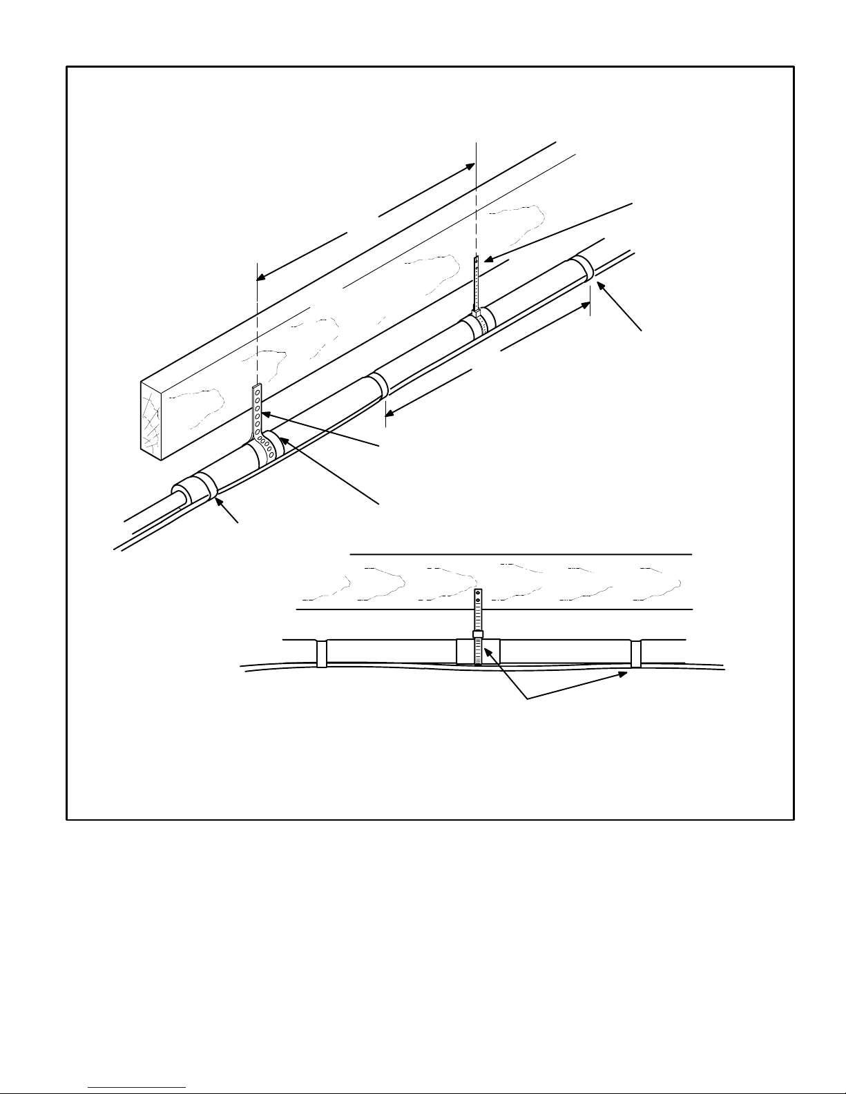
2- Line Set Isolation − The following illustrations demon-
strate procedures which ensure proper refrigerant line
set isolation. Figure 7 shows how to install line sets on
vertical runs. Figure 8 shows how to install line sets on
horizontal runs. Figure 9 shows how to make a transition
from horizontal to vertical. Finally, figure 10 shows how
to place the outdoor unit and line set.
Page 8
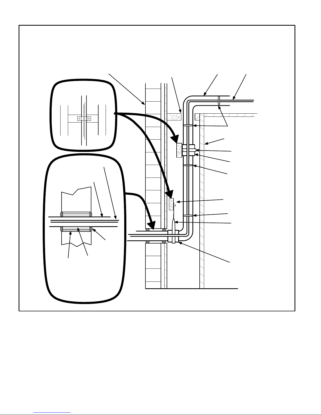
Refrigerant Line Sets
How To Install Vertical Runs
(new construction shown)
PVC Pipe
Fiber Glass
Insulation
Caulk
Outside Wall
Vapor Line
(wrapped with Armaflex)
Liquid Line
IMPORTANT - Refrigerant
lines must not contact
structure.
Outside Wall
Inside Wall
Liquid LineVapor Line
IMPORTANT - Refrigerant
lines must not contact wall.
Wood Block
Between Studs
Strap
Sleeve
Wood Block
Strap
Sleeve
Wire Tie
Wire Tie
Wire Tie
NOTE - Similar installation practices should be used if
line set is to be installed on exterior of outside wall.
Figure 7
Page 9
Refrigerant Line Sets:
Installing Horizontal Runs
8 feet
8 feet
Metal Sleeve
Strapping Material (around vapor line only)
Tape or Wire Tie
Wire Tie
(around vapor line only)
Floor Joist or
Roof Rafter
Tape or Wire Tie
Strap the vapor line to the joist or rafter at 8 ft.
intervals then strap the liquid line to the vapor line.
To hang line set from joist or rafter,
use either metal strapping material
or anchored heavy nylon wire ties.
Floor Joist or Roof Rafter
Figure 8

Page 10
Refrigerant Line Sets:
Transition From Vertical To Horizontal
Liquid Line
Vapor Line
Wrapped in
Armaflex
Strap Liquid Line
To Vapor Line
Metal
Sleeve
Anchored Heavy
Nylon Wire Tie
Automotive
Muffler-Type
Hanger
Wall
Stud
Wall
Stud
Liquid Line
Vapor Line
Wrapped in
Armaflex
Strap Liquid Line
To Vapor Line
Metal
Sleeve
Figure 9
Outside Unit Placement and Installation
Install unit away from windows and
away from neighbors’ windows.
Two 90° elbows
installed in line set
will reduce line set
vibration.
Figure 10
Page 11
WARNING
Polyol ester (POE) oils used with R410A refrigerant
absorb moisture very quickly. It is very important
that the refrigerant system be kept closed as much
as possible. DO NOT remove line set caps or service valve stub caps until you are ready to make
connections.
Brazing Connection Procedure
1 − Cut ends of the refrigerant lines square (free from nicks
or dents). Debur the ends. The pipe must remain
round, do not pinch end of the line.
2 − Before making line set connections, use dry nitrogen to
purge the refrigerant piping. This will help to prevent
oxidation and the introduction of moisture into the system.
3 − Use silver alloy brazing rods (5 or 6 percent minimum
silver alloy for copper−to−copper brazing or 45 percent
silver alloy for copper−to−brass or copper−to−steel brazing) which are rated for use with R410A refrigerant.
Wrap a wet cloth around the valve body and the copper
tube stub. Remove light maroon washers from service
valves and shield light maroon stickers in order to protect them during brazing. Braze the line set to the service valve.
4 − Wrap a wet cloth around the valve body and copper
tube stub to protect it from heat damage during brazing. Wrap another wet cloth underneath the valve body
to protect the base paint.
NOTE − The tube end must stay bottomed in the fitting
during final assembly to ensure proper seating, sealing
and rigidity.
5 − Install the field−provided thermal expansion valve (ap-
proved for use with R410A refrigerant) in the liquid line
at the indoor coil.
Refrigerant Metering Device
HSXA19 units are used in check expansion valve systems
only. See the Lennox Engineering Handbook for approved
TXV match-ups and application information.
Check expansion valves equipped with Chatleff fittings
are available from Lennox. Refer to the Engineering
Handbook for applicable expansion valves for use with
specific match-ups.
If you install a check expansion valve with an indoor coil
that includes a fixed orifice, remove the orifice before
installing the check expansion valve.
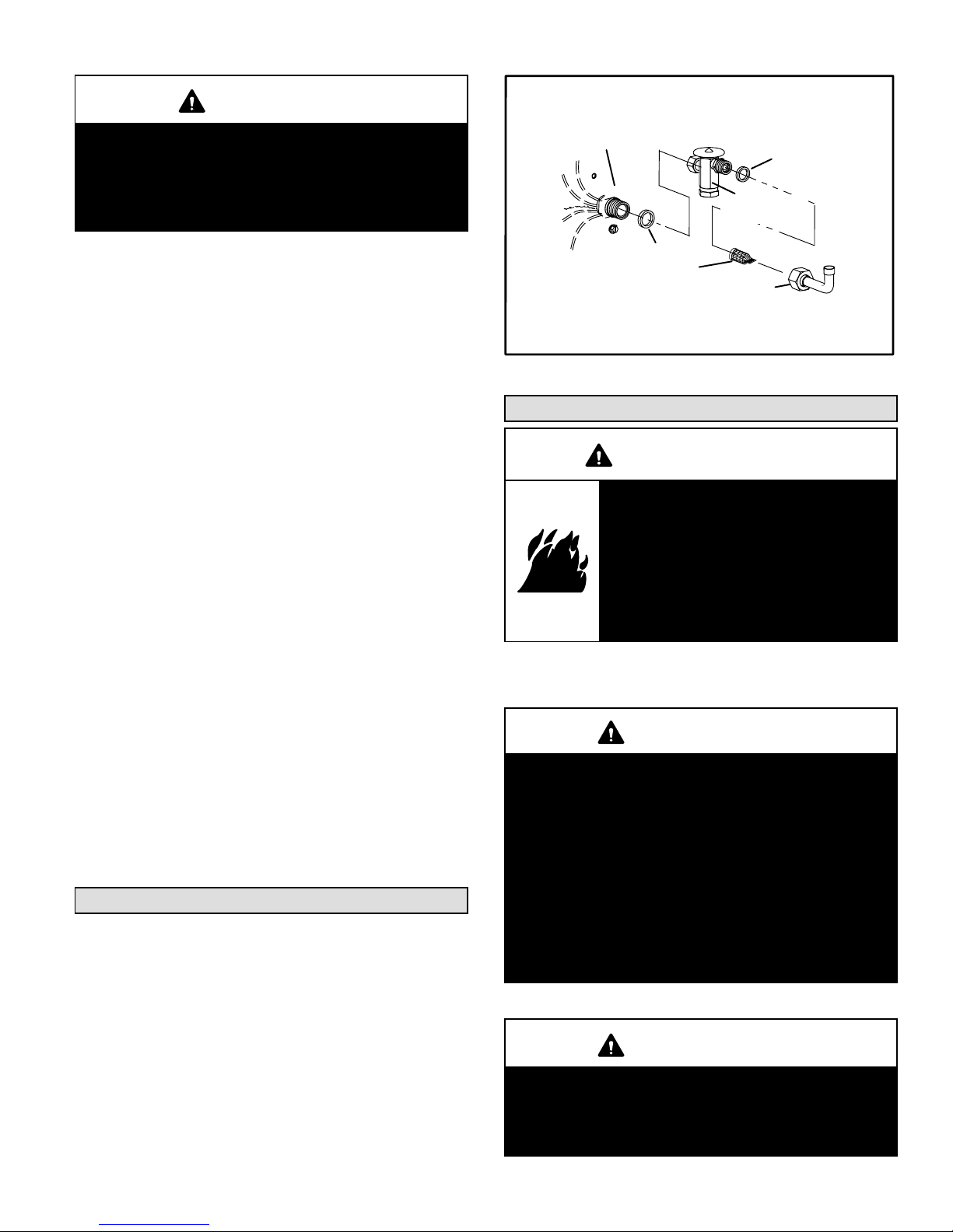
See figure 11 for installation of the check expansion valve.
Metering Device Installation
expansion
valve
o−ring
o−ring
strainer
liquid line
stub
distributor
Figure 11
Flushing Existing Line Set & Indoor Coil
WARNING
Danger of fire. Bleeding the refrigerant
charge from only the high side may
result in the low side shell and suction tubing being pressurized. Appplication of a brazing torch while pressurized may result in ignition of the
refrigerant and oil mixture − check the
high and low pressures before unbrazing.
NOTE − If the indoor unit line and set is new, skip this section and go on to the Manifold Gauge Set section.
IMPORTANT
If this unit is being matched with an approved line
set or indoor coil which was previously charged
with HCFC−22 refrigerant, or if it is being matched
with a coil which was manufactured before January
of 1999, the coil and line set must be flushed prior
to installation. Take care to empty all existing traps.
Polyol ester (POE) oils are used in Lennox units
charged with R410A refrigerant. Residual mineral
oil can act as an insulator, preventing proper heat
transfer. It can also clog the thermal expansion
valve, reducing system performance and capacity.
Failure to properly flush the system per the instructions below will void the warranty.
IMPORTANT
The Environmental Protection Agency prohibits the
intentional venting of HFC refrigerants during maintenance, service, repair and disposal of appliance.
Approved methods of recovery, recycling or reclaiming must be followed.

Page 12
CAUTION
This procedure should not be performed on systems which contain contaminants (Example: compressor burn out).
Required Equipment
You will need the following equipment in order to flush the
existing line set and indoor coil: two clean HCFC−22 recovery bottles, an oilless recovery machine with a pump down
feature, and two sets of gauges (one for use with HCFC−22
and one for use with the R410A).
Flushing Procedure
1 − Remove existing HCFC−22 refrigerant using the ap-
propriate procedure below.
If the existing outdoor unit is not equipped with
shut−off valves, or if the unit is not operational
AND you plan to use the existing HCFC−22 refrigerant to flush the system – Disconnect all power to
the existing outdoor unit. Connect the existing unit, a
clean recovery cylinder and the recovery machine according to the instructions provided with the recovery
machine. Remove all HCFC−22 refrigerant from the
existing system. Refer to gauges after shutdown to
confirm that the entire system is completely void of refrigerant. Disconnect the liquid and vapor lines from
the existing outdoor unit.
If the existing outdoor unit is equipped with
manual shut−off valves AND you plan to use NEW
HCFC−22 refrigerant to flush the system – Start the
existing HCFC−22 system in the cooling mode and
close the liquid line valve. Pump all of the existing
HCFC−22 refrigerant back into the outdoor unit. (It may
be necessary to bypass the low pressure switches to
ensure complete refrigerant evacuation.) When the
low side system pressures reach 0 psig, close the vapor line valve. Disconnect all power to the existing outdoor unit. Refer to gauges after shutdown to confirm
that the valves are not allowing refrigerant to flow back
into the low side of the system. Disconnect the liquid
and vapor lines from the existing outdoor unit.
2 − Remove the existing outdoor unit. Set the new R410A
unit and follow the brazing connection procedure
which begins on the previous page to make line set
connections. DO NOT install metering device at this
time.
Make low voltage and line voltage connections to the
new outdoor unit. DO NOT turn on power to the unit
or open the outdoor unit service valves at this time.
3 − Remove the existing refrigerant flow control orifice or
thermal expansion valve before continuing with flushing procedures. The existing devices are not approved for use with R410A refrigerant and may prevent proper flushing. Use a field−provided fitting to reconnect the lines.
IMPORTANT
The line set and indoor coil must be flushed with at
least the same amount of clean refrigerant that previously charged the system. Check the charge in
the flushing cylinder before proceeding.

Page 13
Flushing Connections
LOW
PRESSURE
HIGH
PRESSURE
VAPOR LINE
SERVICE VALVE
Existing
Indoor Coil
HSXA19 UNIT
GAUGE MANIFOLD
RECOVERY MACHINE
Inverted HCFC−22 Cylinder
(Contains clean HCFC−22 to be
used for flushing)
LIQUID LINE
SERVICE VALVE
INLET
LIQUID
TANK RETURN
CLOSEDOPENED
EXISTING VAPOR LINE
EXISTING LIQUID LINE
RECOVERY
CYLINDER
NOTE − The inverted HCFC−22
cylinder must contain at least
the same amount of refrigerant
as was recovered from the existing system.
Figure 12
4 − Remove the pressure tap valve cores from the
HSXA19 unit’s service valves. Connect an HCFC−22
cylinder with clean refrigerant to the vapor service
valve. Connect the HCFC−22 gauge set to the liquid
line valve and connect a recovery machine with an
empty recovery tank to the gauge set.
5 − Set the recovery machine for liquid recovery and start
the recovery machine. Open the gauge set valves to
allow the recovery machine to pull a vacuum on the existing system line set and indoor coil.
6 − Invert the cylinder of clean HCFC−22 and open its
valve to allow liquid refrigerant to flow into the system
through the vapor line valve. Allow the refrigerant to
pass from the cylinder and through the line set and the
indoor coil before it enters the recovery machine.
7 − After all of the liquid refrigerant has been recovered,
switch the recovery machine to vapor recovery so that
all of the HCFC−22 vapor is recovered. Allow the recovery machine to pull a vacuum on the system.
NOTE − A single system flush should remove all of the
mineral oil from the existing refrigerant lines and indoor coil. A second flushing may be done (using clean
refrigerant) if insufficient amounts of mineral oil were
removed during the first flush. Each time the system
is flushed, you must allow the recovery machine
to pull a vacuum on the system at the end of the
procedure.
8 − Close the valve on the inverted HCFC−22 drum and
the gauge set valves. Pump the remaining refrigerant
out of the recovery machine and turn the machine off.
9 − Use nitrogen to break the vacuum on the refrigerant
lines and indoor coil before removing the recovery machine, gauges and HCFC−22 refrigerant drum. Reinstall pressure tap valve cores into HSXA19 service
valves.
10 − Install the field−provided expansion valve (approved
for use with R410A refrigerant) in the liquid line at the
indoor coil.
Manifold Gauge Set
IMPORTANT
Manifold gauge sets used with systems charged with
R410A refrigerant must be capable of handling the
higher system operating pressures. The gauges
should be rated for use with pressures of 0 − 800 on
the high side and a low side of 30" vacuum to 250 psi
with dampened speed to 500 psi. Gauge hoses must
be rated for use at up to 800 psi of pressure with a
4000 psi burst rating.

Page 14
Service Valves
The liquid line and vapor line service valves (figure 13) and
and gauge ports are used for leak testing, evacuating,
charging and checking charge. See table 2 for torque requirements.
Each valve is equipped with a service port which has a factory−installed Schrader valve. A service port cap protects
the Schrader valve from contamination and serves as the
primary leak seal.
Table 2
Torque Requirements
Part Recommended Torque
Service valve cap 8 ft.− lb. 11 NM
Sheet metal screws 16 in.− lb. 2 NM
Machine screws #10 28 in.− lb. 3 NM
Compressor bolts 90 in.− lb. 10 NM
Gauge port seal cap 8 ft.− lb. 11 NM
To Access Schrader Port:
1 − Remove access panel.
2 − Remove service port cap with an adjustable wrench.
3 − Connect gauge to the service port.
4 − When testing is complete, replace service port cap.
Tighten finger tight, then an additional 1/6 turn.
To Open Service Valve:
1 − Remove stem cap with an adjustable wrench.
2 − Use a service wrench with a hex−head extension to
back the stem out counterclockwise as far as possible.
NOTE − Use a 3/16" hex head extension for liquid line
sizes.
3 − Replace the stem cap. Tighten finger tight, then tighten
an additional 1/6 turn.
To Close Service Valve:
1 − Remove the stem cap with an adjustable wrench.
2 − Use a service wrench with a hex−head extension to
turn the stem clockwise to seat the valve. Tighten it
firmly.
NOTE − Use a 3/16" hex head extension for liquid line
sizes.
3 − Replace the stem cap. Tighten finger tight, then tighten
an additional 1/6 turn.
Ball−Type Vapor Valve – All Units
Vapor line service valves function the same way as the other valves, the difference is in the construction. These
valves are not rebuildable. If a valve has failed, you must
replace it. A ball valve is illustrated in figure 14.
The ball valve is equipped with a service port with a factory−
installed Schrader valve. A service port cap protects the
Schrader valve from contamination and assures a leak−
free seal.
Liquid Line Service Valve
(Valve Closed)
(valve front seated)
to
indoor coil
to outdoor coil
service
port cap
insert hex
wrench here
stem cap
service port
Liquid Line Service Valve
(Valve Open)
valve
core
service port
service
port cap
insert hex
wrench here
to
indoor coil
to outdoor coil
stem
cap
Service Port Is Open
To Line Set When Valve Is
Closed (Front Seated)
Figure 13
Ball−Type Vapor Valve (Valve Open)
Schrader valve
service port
service port
cap
stem cap
stem
Use Adjustable Wrench
To open: rotate Stem Counter-clockwise 90°.
To close: rotate Stem Clockwise 90°.
ball
(shown open)
to outdoor coil
to indoor coil
Figure 14
Page 15
Leak Testing
After the line set has been connected to the indoor and
outdoor units, check the line set connections and indoor
unit for leaks.
WARNING
Refrigerant can be harmful if it is inhaled. Refrigerant must be used and recovered responsibly.
Failure to follow this warning may result in personal
injury or death.
WARNING
Danger of explosion: Can cause
equipment damage, injury or death.
Never use oxygen to pressurize a refrigeration or air conditioning system.
Oxygen will explode on contact with
oil and could cause personal injury.
WARNING
Danger of explosion: Can cause equipment damage,
injury or death. When using a high pressure gas
such as dry nitrogen to pressurize a refrigeration or
air conditioning system, use a regulator that can
control the pressure down to 1 or 2 psig (6.9 to 13.8
kPa).
Using an Electronic Leak Detector
1 − Connect the high pressure hose of the manifold gauge
set to the vapor valve service port. (Normally, the high
pressure hose is connected to the liquid line port, however, connecting it to the vapor port helps to protect the
manifold gauge set from damage caused by high pressure.)
2 − With both manifold valves closed, connect the cylinder
of R410A refrigerant. Open the valve on the R410A cylinder (vapor only).
3 − Open the high pressure side of the manifold to allow
R410A into the line set and indoor unit. Weigh in a trace
amount of R410A. [A trace amount is a maximum of 2
ounces (57 g) refrigerant or 3 pounds (31 kPa) pressure.] Close the valve on the R410A cylinder and the
valve on the high pressure side of the manifold gauge
set. Disconnect R410A cylinder.
4 − Connect a cylinder of nitrogen with a pressure regulat-
ing valve to the center port of the manifold gauge set.
5 − Adjust nitrogen pressure to 150 psig (1034 kPa). Open
the valve on the high side of the manifold gauge set in
order to pressurize the line set and the indoor coil.
6 − After a few minutes, open a refrigerant port to check
that an adequate amount of refrigerant has been added for detection (refrigerant requirements will vary
with line lengths). Check all joints for leaks. Purge nitrogen and R410A mixture. Correct any leaks and recheck.
IMPORTANT
Leak detector must be capable of sensing HFC refrigerant.
Evacuation
Evacuating the system of noncondensables is critical for
proper operation of the unit. Noncondensables are defined
as any gas that will not condense under temperatures and
pressures present during operation of an air conditioning
system. Noncondensables and water vapor combine with
refrigerant to produce substances that corrode copper piping and compressor parts.
IMPORTANT
Use a thermocouple or thermistor electronic vacuum
gauge that is calibrated in microns. Use an instrument
that reads from 50 microns to at least 23,000 microns.
1 − Connect manifold gauge set to the service valve ports :
low pressure gauge to vapor line service valve
high pressure gauge to liquid line service valve
Close manifold gauge set valves. Connect the center
manifold hose to an upright cylinder of R410A .
2 − Connect micron gauge.
3 − Connect the vacuum pump (with vacuum gauge) to the
center port of the manifold gauge set.
4 − Open both manifold valves and start the vacuum
pump.
5 − Evacuate the line set and indoor unit to an absolute
pressure of 23,000 microns (29.01 inches of mercury). During the early stages of evacuation, it is desirable to close the manifold gauge valve at least once to
determine if there is a rapid rise in absolute pressure.
A rapid rise in pressure indicates a relatively large leak.
If this occurs, repeat the leak testing procedure.
NOTE − The term absolute pressure means the total
actual pressure within a given volume or system,
above the absolute zero of pressure. Absolute pressure in a vacuum is equal to atmospheric pressure minus vacuum pressure.
6 − When the absolute pressure reaches 23,000 microns
(29.01 inches of mercury), close the manifold gauge
valves, turn off the vacuum pump and disconnect the
manifold gauge center port hose from vacuum pump.
Attach the manifold center port hose to a nitrogen cylin-
Page 16
der with pressure regulator set to 150 psig (1034 kPa)
and purge the hose. Open the manifold gauge valves
to break the vacuum in the line set and indoor unit.
Close the manifold gauge valves.
WARNING
Danger of Equipment Damage.
Avoid deep vacuum operation. Do not use compressors to evacuate a system.
Extremely low vacuums can cause internal arcing
and compressor failure.
Damage caused by deep vacuum operation will
void warranty.
7 − Shut off the nitrogen cylinder and remove the manifold
gauge hose from the cylinder. Open the manifold
gauge valves to release the nitrogen from the line set
and indoor unit.
8 − Reconnect the manifold gauge to the vacuum pump,
turn the pump on, and continue to evacuate the line set
and indoor unit until the absolute pressure does not
rise above 500 microns (29.9 inches of mercury) within
a 20−minute period after shutting off the vacuum pump
and closing the manifold gauge valves.
9 − When the absolute pressure requirement above has
been met, disconnect the manifold hose from the vacuum pump and connect it to an upright cylinder of R410A
refrigerant. Open the manifold gauge valves to break
the vacuum from 1 to 2 psig positive pressure in the line
set and indoor unit. Close manifold gauge valves and
shut off the R410A cylinder and remove the manifold
gauge set.
Start−Up
1 − Rotate fan to check for frozen bearings or binding.
2 − Inspect all factory− and field−installed wiring for loose
connections.
3 − After evacuation is complete, open the liquid line and
vapor line service valves to release the refrigerant
charge (contained in outdoor unit) into the system.
4 − Replace the stem caps and secure finger tight, then
tighten an additional one-sixth (1/6) of a turn.
5 − Check voltage supply at the disconnect switch. The
voltage must be within the range listed on the unit’s
nameplate. If not, do not start the equipment until you
have consulted the power company and the voltage
condition has been corrected.
6 − Set the thermostat for a high stage cooling demand (Y1
and Y2 demand). Turn on power to the indoor blower
and close the outdoor unit disconnect switch to start
the unit.
7 − Recheck voltage while the unit is running. Power must
be within range shown on the nameplate.
Charging
This system is charged with R410A refrigerant which operates at much higher pressures than HCFC−22. This unit is
NOT approved for use with coils which include metering
orifices or capillary tubes.
Processing Procedure
Units are factory charged with the amount of R410A refrigerant indicated on the unit rating plate. This charge is
based on a matching indoor coil and outdoor coil with 15
feet (4.6 m) line set. For varying lengths of line set, refer to
table 3 for refrigerant charge adjustment.
Table 3
Liquid Line Set
Diameter
Oz. per 5 ft. (grams per 1.5m) adjust
from 15 ft. (4.6 m) line set*
3/8 in.
(10 mm)
3 ounces per 5 feet
(85 g per 1.5 m)
*If line length is greater than 15 ft. (4.6 m), add this amount.
If line length is less than 15 ft. (4.6 m), subtract this amount.
IMPORTANT
Mineral oils are not compatible with R410A. If oil
must be added, it must be a polyol ester oil.
The compressor is charged with sufficient polyol ester
oil for line set lengths up to 50 feet (15.2 m).
If the system is void of refrigerant, clean the system using the procedure described below.
1 − Use nitrogen to pressurize the system and check for
leaks. Repair leaks, if possible.
2 − Evacuate the system to remove as much of the mois-
ture as possible (triple evacuation).
3 − Evacuate the system again. Then, weigh the appropri-
ate amount of R410A refrigerant (listed on unit nameplate) into the system.
4 − Start the unit and monitor the system to determine the
amount of moisture remaining in the oil. Use test kit
10N46 to verify that the moisture content is within the
kit’s dry color range.
5 − If the moisture content is not within the dry color range,
add a new filter drier between the liquid valve and the
TXV. You may have to add a new filter drier several
times to achieve the required level of dryness.
If system dryness is not verified, the compressor
will fail in the future.
The outdoor unit should be charged during warm weather.
However, applications arise in which charging must occur
in the colder months. The method of charging is deter-
mined by the outdoor ambient temperature.
Measure the liquid line temperature and the outdoor ambient temperature as outlined below:
1 − Connect the manifold gauge set to the service valves:
low pressure gauge to vapor valve service port
high pressure gauge to liquid valve service port
Page 17
Connect the center manifold hose to an upright cylinder of R410A. Close manifold gauge set valves.
2 − Set the room thermostat to call for heat. This will create
the necessary load for properly charging the system in
the cooling cycle.
3 − Use a digital thermometer to record the outdoor ambi-
ent temperature.
4 − When the heating demand has been satisfied, switch
the thermostat to cooling mode with a set point of 68F
(20C). When pressures have stabilized, use a digital
thermometer to record the liquid line temperature.
5 − The outdoor temperature will determine which charg-
ing method to use. Proceed with the appropriate charging procedure.
Weighing in the Charge TXV Systems –
Outdoor Temp. < 65F (18C)
If the system is void of refrigerant, or if the outdoor ambient
temperature is cool, the refrigerant charge should be
weighed into the unit. Do this after any leaks have been repaired.
1 − Recover the refrigerant from the unit.
2 − Conduct a leak check, then evacuate as previously
outlined.
3 − Weigh in the unit nameplate charge.
If weighing facilities are not available or if you are charging
the unit during warm weather, follow one of the other procedures outlined below.
Subcooling Method
Outdoor Temp. < 65°F (18°C)
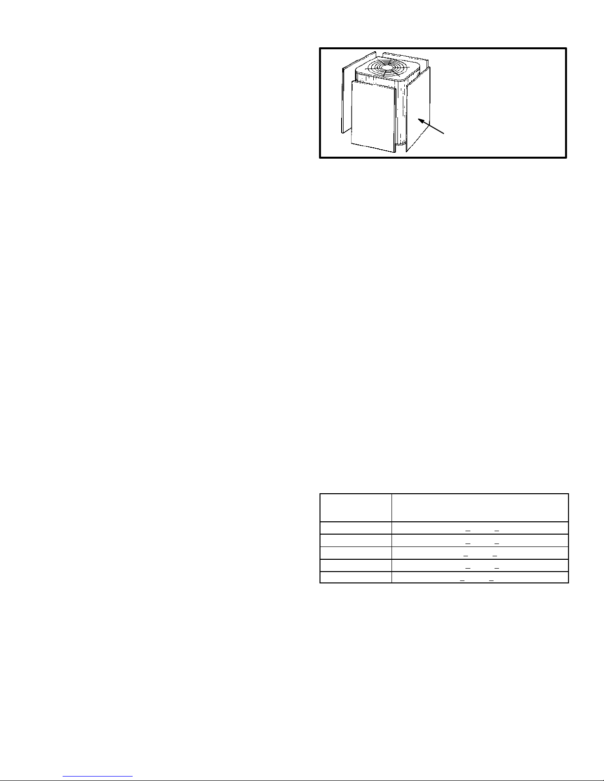
When the outdoor ambient temperature is below 65°F
(18°C), use the subcooling method to charge the unit. It
may be necessary to restrict the air flow through the outdoor coil to achieve pressures in the 325−375 psig
(2240−2585 kPa) range. These higher pressures are necessary for checking the charge. Block equal sections of air
intake panels and move obstructions sideways until the liquid pressure is in the 325−375 psig (2240−2585 kPa) range.
See figure 15.
Blocking Outdoor Coil
cardboard or
plastic sheet
*Outdoor coil should be
blocked one side
at a time with cardboard
or plastic sheet until proper
testing pressures
are reached.
Figure 15
*Four−sided
unit shown.
1 − With the manifold gauge hose still on the liquid service
port and the unit operating stably, use a digital ther-
mometer to record the liquid line temperature.
2 − At the same time, record the liquid line pressure reading.
3 − Use a temperature/pressure chart for R410A to deter-
mine the saturation temperature for the liquid line pres-
sure reading. See table 7.
4 − Subtract the liquid line temperature from the saturation
temperature (according to the chart) to determine sub-
cooling. (Saturation temperature − Liquid line tem-
perature = Subcooling)
5 − Compare the subcooling value with those in table 4. If
subcooling is greater than shown, recover some refrig-
erant. If subcooling is less than shown, add some re-
frigerant. Be aware of the R410A refrigerant cylinder. It
will be light maroon−colored. Refrigerant should be
added through the vapor line valve in the liquid state.
Some R410A cylinders are equipped with a dip
tube that allows you to draw liquid refrigerant from
the bottom of the cylinder without turning the cyl-
inder upside−down. The cylinder will be marked if it
is equipped with a dip tube.
Table 4
Subcooling Values for Charging
Model Number
Second Stage (High Capacity)
Subcooling Values
Saturation Temp. − Liquid Line Temp. °F (°C)
HSXA19−024 10.0 + 1 (5.6 + .5)
HSXA19−036 10.0 + 1 (5.6 + .5)
HSXA19−038 5.3 + 1 (2.9 + .5)
HSXA19−048 10.0 + 1 (5.6 + .5)
HSXA19−060 7 + 1 (3.9 + .5)
Page 18
Charging Using Normal Operating Pressures
and the Approach Method
Outdoor Temp. >
65F (18C)
The following procedure is intended as a general guide and
is for use on expansion valve systems only. For best results,
indoor temperature should be 70°F (21°C) to 80°F (26°C).
Monitor system pressures while charging.
1 − Record outdoor ambient temperature using a digital
thermometer.
2 − Attach high pressure gauge set and operate unit for
several minutes to allow system pressures to stabilize.
3 − Compare stabilized pressures with those provided in
table 6, Normal Operating Pressures." Minor variations in these pressures may be expected due to differences in installations. Significant differences could
mean that the system is not properly charged or that a
problem exists with some component in the system.
Pressures higher than those listed indicate that the
system is overcharged. Pressures lower than those
listed indicate that the system is undercharged. A temperature/pressure chart for R410A refrigerant is provided in table 5 for your convenience. Verify adjusted
charge using the approach method.
Approach Method
4 − Use the same digital thermometer you used to check
the outdoor ambient temperature to check the liquid
line temperature.
5 − The difference between the ambient and liquid temper-
atures should match values given in table 5. If the values don’t agree with the those in table 5, add refrigerant to lower the approach temperature, or recover refrigerant from the system to increase the approach
temperature. Be aware of the R410A refrigerant cylinder. It will be light maroon−colored. Refrigerant should
be added through the vapor valve in the liquid state.
Some R410A cylinders are equipped with a dip
tube which allows you to draw liquid refrigerant
from the bottom of the cylinder without turning the
cylinder upside−down. The cylinder will be marked
if it is equipped with a dip tube.
Table 5
Model Number
Second Stage (High Capacity)
Approach Temperature
Liquid Line Temp. − Outdoor Ambient °F (°C)
HSXA19−024 1.9 + 1 (1 + .5)
HSXA19−036 6.2 + 1 (3.5 + .5)
HSXA19−038 7.5 + 1 (4.3 + .5)
HSXA19−048 6.0 + 1 (3.3 + .5)
HSXA19−060 10.0 + 1 (5.6 + .5)
NOTE − For best results, the same electronic thermometer
should be used to check both outdoor ambient and liquid line
temperatures.
IMPORTANT
Use table 6 to perform maintenance checks. Table 6
is not a procedure for charging the system. Minor
variations in these pressures may be due to differences in installations. Significant deviations could
mean that the system is not properly charged or that
a problem exists with some component in the system.

Page 19
Table 6
Normal Operating Pressure
s
(Liquid ±10 and Vapor ±5 psig)
First Stage (Low Capacity)
Outdoor Coil Entering
Air Tem
p
. °F (°C
)
−024
−036 −038 −048 −060
Air Temp. F (C)
Liquid Vapor
Liquid Vapor Liquid Vapor Liquid Vapor Liquid Vapor
65 (18.3)
215 144
224 135 215 144 216 138 233 143
75 (23.9)
248 146
258 139 252 146 249 140 270 145
85 (29.4)
288 148
300 143 293 148 288 143 312 147
95 (35.0)
331 150
342 147 337 150 332 145 358 147
105 (40.6)
380 152
395 148 388 154 380 147 407 149
115 (46.1) 432 155 451 149 443 156 430 150 456 150
Second Stage (High Capacity)
Outdoor Coil Entering
Air Tem
p
. °F (°C
)
−024
−036 −038 −048 −060
Air Temp. F (C)
Liquid Vapor
Liquid Vapor Liquid Vapor Liquid Vapor Liquid Vapor
65 (18.3)
222 142
233 131 224 133 226 132 251 127
75 (23.9)
258 144
266 134 259 139 261 135 291 135
85 (29.4)
300 146
306 137 299 143 301 137 334 141
95 (35.0)
343 148
361 141 343 146 347 140 375 142
105 (40.6)
394 150
401 142 395 148 395 142 434 146
115 (46.1) 446 153 455 144 448 150 448 145 487 149

Page 20
Table 7
R410A Temperature/Pressure Chart
Temperature°FPressure
Psig
Temperature°FPressure
Psig
Temperature°FPressure
Psig
Temperature°FPressure
Psig
32 100.8 63 178.5 94 290.8 125 445.9
33 102.9 64 181.6 95 295.1 126 451.8
34 105.0 65 184.3 96 299.4 127 457.6
35 107.1 66 187.7 97 303.8 128 463.5
36 109.2 67 190.9 98 308.2 129 469.5
37 111.4 68 194.1 99 312.7 130 475.6
38 113.6 69 197.3 100 317.2 131 481.6
39 115.8 70 200.6 101 321.8 132 487.8
40 118.0 71 203.9 102 326.4 133 494.0
41 120.3 72 207.2 103 331.0 134 500.2
42 122.6 73 210.6 104 335.7 135 506.5
43 125.0 74 214.0 105 340.5 136 512.9
44 127.3 75 217.4 106 345.3 137 519.3
45 129.7 76 220.9 107 350.1 138 525.8
46 132.2 77 224.4 108 355.0 139 532.4
47 134.6 78 228.0 109 360.0 140 539.0
48 137.1 79 231.6 110 365.0 141 545.6
49 139.6 80 235.3 111 370.0 142 552.3
50 142.2 81 239.0 112 375.1 143 559.1
51 144.8 82 242.7 113 380.2 144 565.9
52 147.4 83 246.5 114 385.4 145 572.8
53 150.1 84 250.3 115 390.7 146 579.8
54 152.8 85 254.1 116 396.0 147 586.8
55 155.5 86 258.0 117 401.3 148 593.8
56 158.2 87 262.0 118 406.7 149 601.0
57 161.0 88 266.0 119 412.2 150 608.1
58 163.9 89 270.0 120 417.7 151 615.4
59 166.7 90 274.1 121 423.2 152 622.7
60 169.6 91 278.2 122 428.8 153 630.1
61 172.6 92 282.3 123 434.5 154 637.5
62 195.5 93 286.5 124 440.2 155 645.0
Page 21
System Operation
The outdoor unit and indoor blower cycle on demand from
the room thermostat. When the thermostat blower switch is
in the ON position, the indoor blower operates continuously.
Two−Stage Compressor
The two stage scroll compressor operates much like the
standard scroll compressor with the exception the two step
compressor steps between low capacity and full capacity.
The steps occur when gas is bypassed through a vent port
in the first suction pocket. This bypassing of gas allows the
compressor to operate at low capacity if thermostat demand allows, creating a more cost effective and efficient
compressor.
Full capacity is achieved by blocking the vent port with a
slider ring. The slider ring (vent port cover) is controlled by a
24VDC internal solenoid in the open position allowing low
capacity. When energized the internal solenoid closes the
slider ring, blocking the vent port and bringing the compressor to full capacity. Stepping can occur during a single thermostat demand as the motor runs continuously while the
compressor steps from low to full capacity.
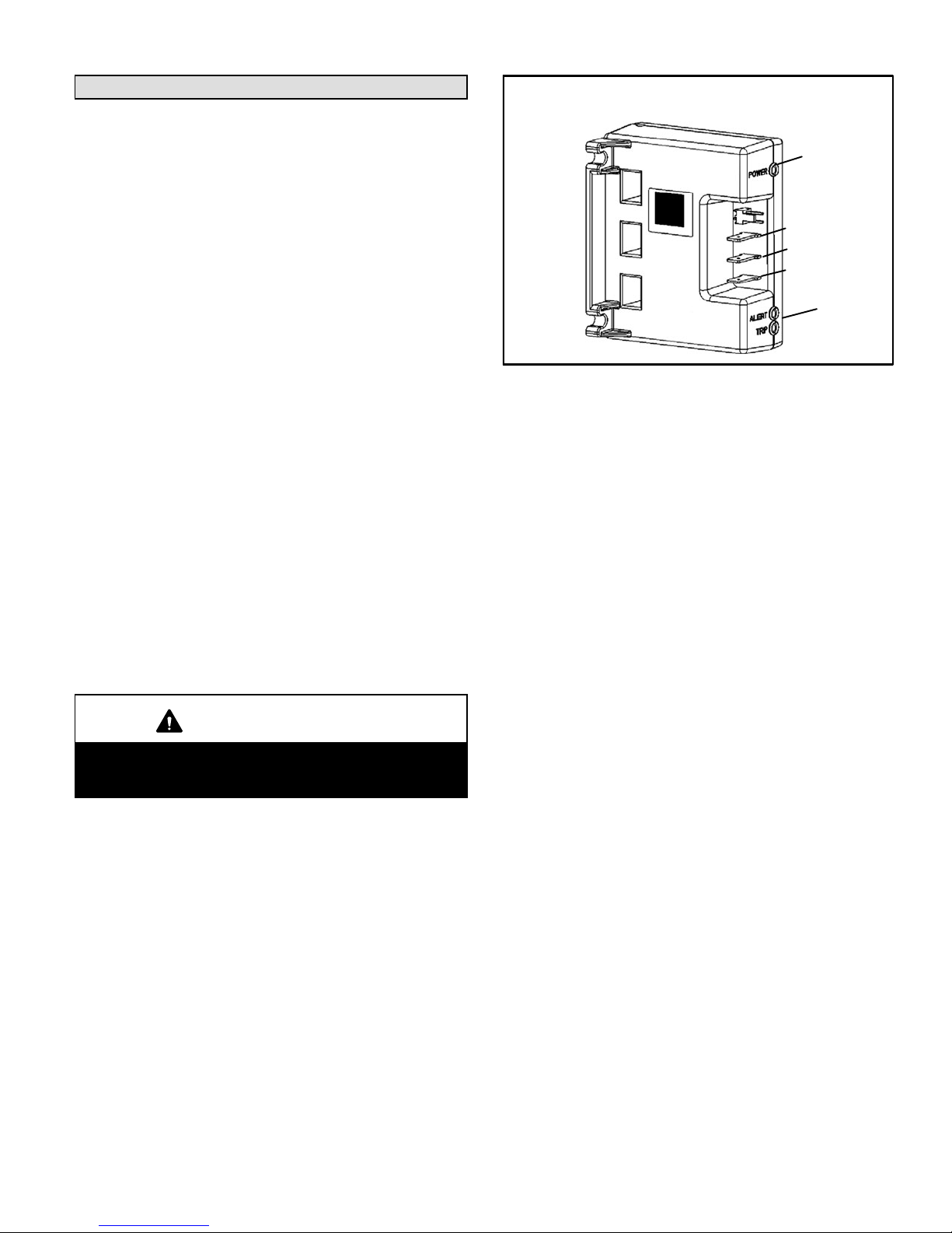
System Operation Monitor
The diagnostic indicator detects the most common fault
conditions in the air conditioning system. When an abnormal condition is detected, the module communicates the
specific condition through its ALERT and TRIP lights. The
module is capable of detecting both mechanical and electrical system problems. See figure 1 for the system operation monitor
IMPORTANT
This monitor does not provide safety protection. The
monitor is a monitoring device only and cannot control or shut down other devices.
System Operation Monitor
Y
C
R
LED
LED’s
Figure 1
LED Functions
Alert LED (yellow) − communicates an abnormal system
condition through a unique flash code. The alert LED will
flash a number of times consecutively, pause and then repeat the process. The number of consecutive flashes, defined as the Flash Code, correlates to a particular abnormal
condition.
Trip LED (red) − indicates there is a demand signal from the
thermostat but no current to the compressor is detected by
the module.
Flash code number corresponds to a number of LED
flashes, followed by a pause, and then repeated.
TRIP and ALERT LEDs flashing at the same time indicates
that the control circuit voltage is too low for operation.
Reset ALERT flash code by removing 24VAC power from
monitor. Last ALERT flash code will display for 1 minute after monitor is powered on.

Page 22
Table 1
System Operation Monitor LED Troubleshooting Codes
Status LED Status LED Description Status LED Troubleshooting Information
Green Power" Module has power. 24VAC control power is present at the module terminal.
Red Trip"
Thermostat demand signal
Y1 is present, but the compressor is not running.
1
Compressor protector is open.
2
Outdoor unit power disconnect is open.
3
Compressor circuit breaker or fuse(s) is open.
4
Broken wire or connector is not making contact.
5
Low pressure switch open if present in the system.
6
Compressor contactor has failed to close.
Yellow Alert"
Flash Code 1
(Does not apply to heat
pump or to two−stage
split systems)
Long Run Time
Compressor is running extremely long run cycles
1
Low refrigerant charge.
2
Evaporator blower is not running.
3
Evaporator coil is frozen.
4
Faulty metering device.
5
Condenser coil is dirty
6
Liquid line restriction (filter drier blocked if present)
7
Thermostat is malfunctioning
.
Yellow Alert"
Flash Code 2
System Pressure Trip
Discharge or suction pressure out of limits or
compressor overloaded
1
High head pressure.
2
Condenser coil poor air circulation (dirty, blocked, damaged).
3
Condenser fan is not running.
4
Return air duct has substantial leakage.
5
If low pressure switch is present, check Flash Code 1 information.
Yellow Alert"
Flash Code 3
Short Cycling
Compressor is
running
only briefly
1
Thermostat demand signal is intermittent.
2
Time delay relay or control board is defective.
3
If high pressure switch is present, check Flash Code 2 information.
4
If low pressure switch is present, check Flash Code 1 information.
Yellow Alert"
Flash Code 4
Locked Rotor
1
Run capacitor has failed.
2
Low line voltage (contact utility if voltage at disconnect is low).
3
Excessive liquid refrigerant in the compressor.
4
Compressor bearings are seized.
Yellow Alert"
Flash Code 5
Open Circuit
1
Outdoor unit power disconnect is open.
2
Unit circuit breaker or fuse(s) is open.
3
Unit contactor has failed to close.
4
High pressure switch is open and requires manual reset.
5
Open circuit in compressor supply wiring or connections.
6
Unusually long compressor protector reset time due to extreme ambient temperature.
7
Compressor windings are damaged.
Yellow Alert"
Flash Code 6
Open Start Circuit
Current only in run circuit
1
Run capacitor has failed.
2
Open circuit in compressor start wiring or connections.
3
Compressor start winding is damaged.
Yellow Alert"
Flash Code 7
Open Run Circuit
Current only in start circuit
1
Open circu it in compr es sor s tart wiring or connections.
2
Compressor start winding is damaged.
Yellow Alert"
Flash Code 8
Welded Contactor
Compressor always runs
1
Compressor contactor failed to open.
2
Thermostat demand signal not connected to module.
Yellow Alert"
Flash Code 9
Low Voltage
Control circuit < 17VAC
1
Control circuit transformer is overloaded
2
Low line voltage (contact utility if voltage at disconnect is low.)
Flash code number corresponds to a number of LED flashes, followed by a pause, and then repeated.
TRIP and ALERT LEDs flashing at the same time indicates that the control circuit voltage is too low for operation.
Reset ALERT flash code by removing 24VAC power from monitor. Last ALERT flash code will display for 1 minute after monitor is powered on.
Filter Drier
A drier is factory−installed in each HSXA19 unit. A replacement drier is available from Lennox. See the Lennox Engineering Handbook.
High Pressure Switch
HSXA19 units are equipped with a high pressure switch
that is located in the liquid line of the compressor. The
switch (SPST, manual reset, normally closed) removes
power from the compressor when liquid pressure rises
above factory setting at 640 +
10 psi.
Low Pressure Switch
HSXA19 units are also equipped with a low pressure switch
that is located in the vapor line of the compressor. The
switch (SPST, auto−reset, normally closed) removes power
from the compressor when vapor line pressure drops below factory setting at 40 +
5 psi.
Variable Speed Condenser Fan Motor (−038 only)
The HSXA19 is equipped with a variable speed condenser
fan motor that operates at two speeds. The thermostat controls the speed selection.

Page 23
Maintenance
Before the start of each heating and cooling season, the
following service checks should be performed by a
qualified service technician.
As always, electrical power to the unit must be turned
off prior to any unit maintenance.
WARNING
Electric shock hazard. Can cause injury or death. Before attempting to perform any service or maintenance, turn
the electrical power to unit OFF at disconnect switch(es). Unit may have
multiple power supplies.
The outdoor and indoor coils should be inspected
and cleaned. The outdoor coil may be flushed with
a water hose.
NOTE − It may be necessary to flush the outdoor
coil more frequently if it is exposed to substances
which are corrosive or which block airflow across
the coil (e.g., pet urine, cottonwood seeds, etc.)
The refrigerant lines should be visually inspected and
the coils should be checked for leaks.
Wiring should be checked for loose connections.
Voltage must be checked at the indoor and outdoor
units (units operating).
The amp-draw at the outdoor fan motor and indoor
blower motor should be checked. Values should be
compared with those given on unit nameplate.
Indoor unit filters should be cleaned or replaced.
The refrigerant charge should be checked and
system pressures should be gauged.
The condensate drain line should be checked for
free and unobstructed flow and it should be
cleaned, if necessary.
Condenser fan motor is prelubricated and sealed.
No further lubrication is needed.
NOTE − If owner complains of insufficient cooling, the unit
should be gauged and refrigerant charge checked. Refer
to section on refrigerant charging in this instruction.
Optional Accessories
Refer to the Engineering Handbook for optional accessories that may apply to this unit. The following may or may
not apply:
Loss of Charge Kit
High Pressure Switc Kit
Compressor Monitor
Compressor Crankcase Heater
Hail Guards
Mounting Bases
Timed Off Control
Stand−off Kit
Sound Cover
Low Ambient Kit
Dave Lennox Signature Room Thermostat
Homeowner Information
In order to ensure peak performance, your system must
be properly maintained. Clogged filters and blocked
airflow prevent your unit from operating at its most
efficient level.
Ask your Lennox dealer to show you where your indoor
unit’s filter is located. It will be either at the indoor unit
(installed internal or external to the cabinet) or behind a
return air grille in the wall or ceiling. Check the filter
monthly and clean or replace it as needed.
Disposable filters should be replaced with a filter of the
same type and size. If you are unsure about the filter you
need for your system, call your Lennox dealer for assistance.
IMPORTANT
Turn off electrical power to the unit at the disconnect
switch before performing any maintenance. The unit
may have multiple power supplies.
Many indoor units are equipped with reusable foam filters. These filters can be cleaned with a mild soap and
water solution. Rinse the filter thoroughly and let it dry
completely, before it is returned to the unit or grille.
The filter and all access panels must be in place any
time the unit is in operation.
Your system may be equipped with an electronic air
cleaner which will provide respiratory relief by removing
up to 90 percent of all airborne particles which pass
through it. If it is, ask your dealer to instruct you on its
maintenance.

Page 24
Your indoor evaporator coil is equipped with a drain pan
to collect condensate formed as your system removes
humidity from the inside air. Have your dealer show you
where the main condensate drain (and auxiliary drain, if
applicable) runs and how to check the drain for any obstruction.
It is also very important to provide unrestricted airflow to
the outdoor unit. Leaves, trash or shrubs crowding the
unit cause the outdoor unit to work harder and use more
energy. Keep shrubbery trimmed away from the unit and
periodically check for debris which may have collected
around the unit.
Thermostat Operation
Though your thermostat may vary somewhat from the
description below, its operation will be similar.
Temperature Setting Levers
Set the lever or dial to the desired temperature setpoints
for both heating and cooling. Avoid frequent temperature
adjustment; turning the unit off and back on before pressures equalize puts stress on the unit compressor.
Fan Switch
In AUTO or INT (intermittent) mode, the blower operates
only when the thermostat calls for heating or cooling.
This mode is generally preferred when humidity control
is a priority. The ON or CONT mode provides continuous
indoor blower operation, regardless of whether the compressor or furnace is operating. This mode is required
when constant air circulation or filtering is desired.
System Switch
Set the system switch for heating, cooling or auto operation. The auto mode allows the system to automatically
switch from heating mode to cooling mode to maintain
predetermined comfort settings.
Temperature Indicator
The temperature indicator displays the actual room
temperature.
Programmable Thermostats
Your Lennox system may be controlled by a
programmable thermostat. These thermostats provide
the added feature of programmable time-of-day setpoints
for both heating and cooling. Refer to the user’s
information manual provided with your particular
thermostat for operation details.
Preservice Check
If your system fails to operate, check the following before
calling for service:
Check to see that all electrical disconnect switches
are ON.
Make sure the room thermostat temperature
selector is properly set.
Make sure the room thermostat system switch is
properly set.
Replace any blown fuses, or reset circuit breakers.
Make sure unit access panels are in place.
Make sure air filter is clean.
Locate unit model number and have it handy
before calling.
Check Points
Start−Up and Performance Check List
Job Name
Job Location
Installer
Unit Model No.
Nameplate Voltage
Minimum Circuit Ampacity
Maximum Overcurrent Protection Size
Refrigerant Lines:
Service Valves Fully Opened?
Outdoor Fan Checked?
Job No.
City
City
Serial No.
Date
State
State
Service Technician
Amps:
Compressor Amperage:
Indoor Filter Clean?
Electrical Connections Tight?
Supply Voltage (Unit Off)
First Stage
Thermostat
Refrigerant Charge Checked?
Calibrated? Properly Set?
Level?
Properly Insulated?
Voltage With Compressor Operating
Leak Checked?
Service Valve Caps Tight?
Indoor Blower RPM
Outdoor Coil Entering Air Temp.
Liquid Pressure:
S.P. Drop Over Indoor (Dry)
first−stage second−stage
First StageVapor Pressure: Second Stage
Second Stage
first−stage
second−stage
 Loading...