

Lennox HSXA16-024, HSXA16, HSXA16-036, HSXA16-048, HSXA16-060 Installation Instructions Manual
INSTALLATION
2006 Lennox Industries Inc.
Dallas, Texas, USA
RETAIN THESE INSTRUCTIONS
FOR FUTURE REFERENCE
WARNING
Improper installation, adjustment, alteration, service or maintenance can cause property damage,
personal injury or loss of life. Installation and service must be performed by a qualified installer or
service agency.
CAUTION
Physical contact with metal edges and corners
while applying excessive force or rapid motion can
result in personal injury. Be aware of, and use
caution when working near these areas during
installation or while servicing this equipment.
INSTRUCTIONS
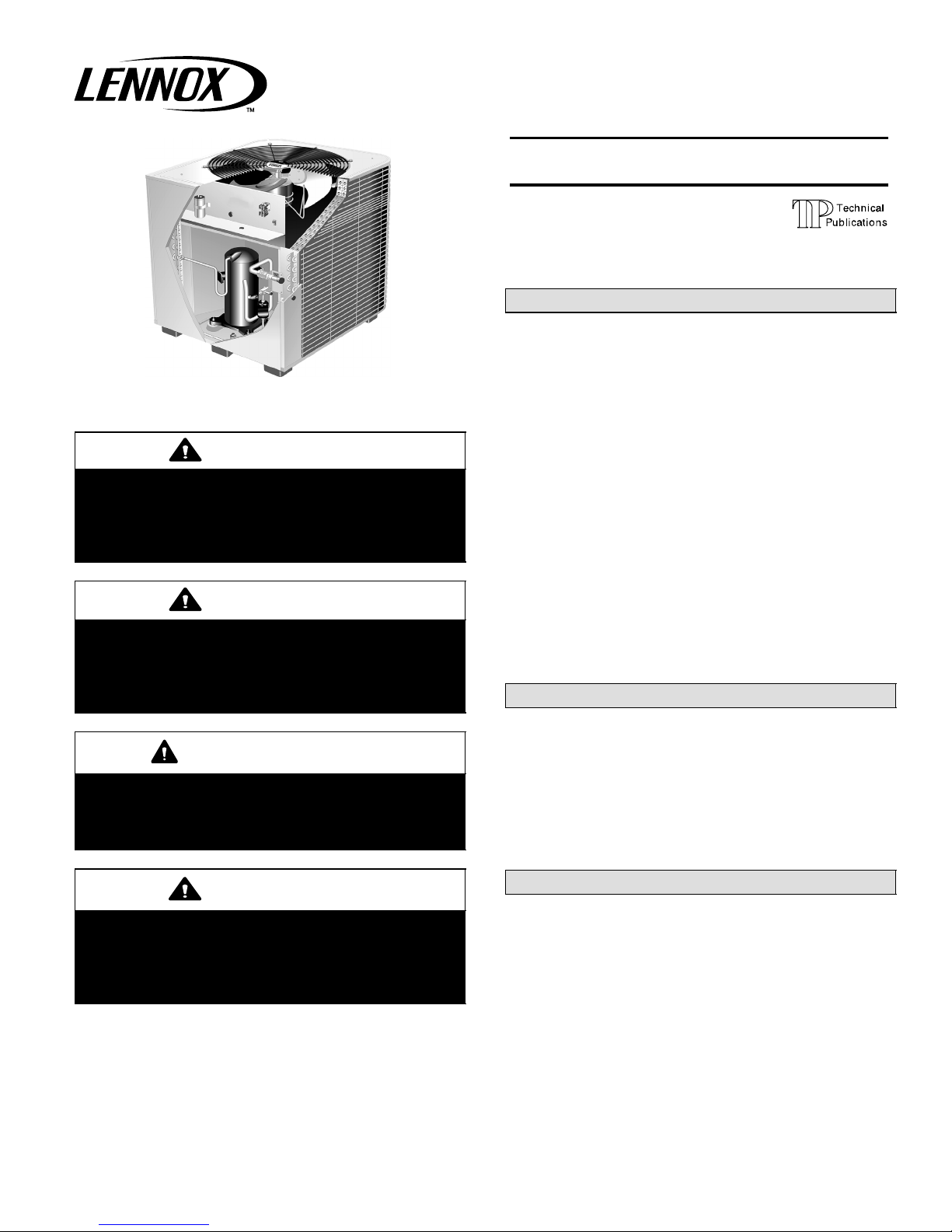
HSXA16 Series Units
CONDENSING UNITS
504,953M
07/06
Supersedes 03/06
Table of Contents
HSXA16 Outdoor Unit 1. . . . . . . . . . . . . . . . . . . . . . . . . .
Shipping & Packing List 1. . . . . . . . . . . . . . . . . . . . . . . .
General Information 2. . . . . . . . . . . . . . . . . . . . . . . . . . .
Unit Dimensions 2. . . . . . . . . . . . . . . . . . . . . . . . . . . . . . .
Setting The Unit 3. . . . . . . . . . . . . . . . . . . . . . . . . . . . . . .
Electrical 3. . . . . . . . . . . . . . . . . . . . . . . . . . . . . . . . . . . . .
Refrigerant Piping 5. . . . . . . . . . . . . . . . . . . . . . . . . . . . .
Refrigerant Metering Device 8. . . . . . . . . . . . . . . . . . . .
Flushing Existing Line Set & Indoor Coil 8. . . . . . . . . .
Manifold Gauge Set 9. . . . . . . . . . . . . . . . . . . . . . . . . . .
Service Valves 10. . . . . . . . . . . . . . . . . . . . . . . . . . . . . . . .
Leak Testing 11. . . . . . . . . . . . . . . . . . . . . . . . . . . . . . . . . .
Evacuation 11. . . . . . . . . . . . . . . . . . . . . . . . . . . . . . . . . . .
Start−Up 12. . . . . . . . . . . . . . . . . . . . . . . . . . . . . . . . . . . . . .
Refrigerant Charging 12. . . . . . . . . . . . . . . . . . . . . . . . . . .
System Operation 14. . . . . . . . . . . . . . . . . . . . . . . . . . . . .
Maintenance 15. . . . . . . . . . . . . . . . . . . . . . . . . . . . . . . . . .
Optional Accessories 15. . . . . . . . . . . . . . . . . . . . . . . . . .
Homeowner Information 15. . . . . . . . . . . . . . . . . . . . . . . .
Thermostat Operation 16. . . . . . . . . . . . . . . . . . . . . . . . . .
Start-up & Performance Check List 16. . . . . . . . . . . . . .
HSXA16 Outdoor Unit
Litho U.S.A.
Two−stage HSXA16 outdoor units use HFC−410A refriger-
IMPORTANT
This unit must be matched with an indoor coil as
specified in Lennox’ Engineering Handbook.
Coils previously charged with HCFC−22 must be
flushed.
IMPORTANT
The Clean Air Act of 1990 bans the intentional venting of refrigerant (CFC’s, HCFC’s AND HFC’s) as of
July 1, 1992. Approved methods of recovery, recycling or reclaiming must be followed. Fines and/or incarceration may be levied for noncompliance.
07/06 504,953M
ant. This unit must be installed with a matching indoor coil
and line set as outlined in the Lennox Engineering Handbook. Elite® Series HSXA16 outdoor units are designed for
use in thermostatic expansion valve (TXV) systems only
and are not for use with other refrigerant flow control devices. The Lennox Engineering Handbook lists a TXV kit
that must be ordered separately.
Shipping & Packing List
1 − Assembled HSXA16 outdoor unit
2 − Grommets (liquid and vapor line)
1 − Bushing (for low voltage wiring)
Check equipment for shipping damage. If you find any
damage, immediately contact the last carrier.
Page 1
*2P0706* *P504953M*
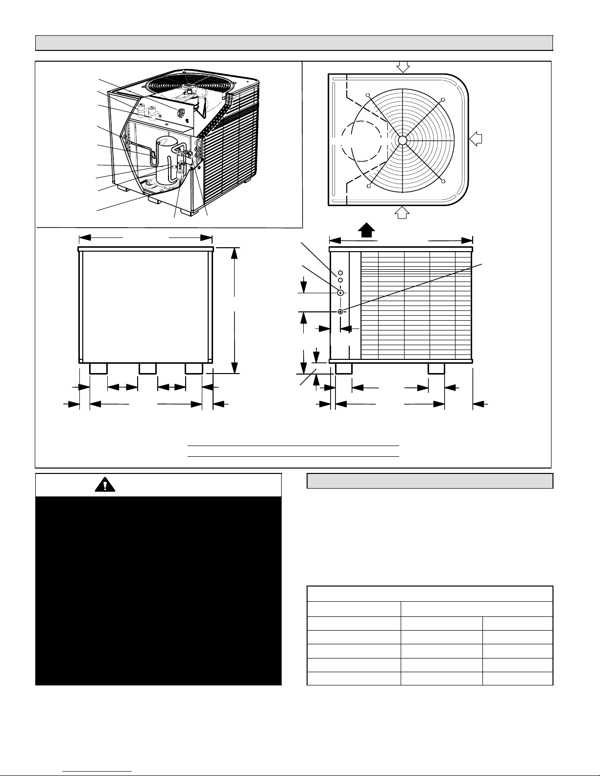
Unit Dimensions − inches (mm)
Parts Arrangement
CONTACTOR
RUN CAPACITOR
START CAPACITOR
(MODEL −024)
DISCHARGE LINE
COMPRESSOR
TERMINAL PLUG
TWO−STAGE
COMPRESSOR
VAPOR LINE
LOW PRESSURE
SWITCH
HIGH PRESSURE
SWITCH
FILTER DRIER
32-1/8 (816)
VAPOR VALVE AND GAUGE PORT
ELECTRICAL
INLETS
SUCTION
LINE INLET
A
4-1/2
(114)
B
INLET AIR
COMPRESSOR
TOP VIEW
2-9/16
(65)
INLET
AIR
INLET AIR
DISCHARGE AIR
34-1/16 (865)
LIQUID
LINE INLET
2-1/4
(57)
3-1/8
(79)
9-1/8
(232)
27-5/8
3-1/8
(702)
(79)
9-1/8
(232)
3-1/8
(79)
2-1/4
(57)
2-3/4 (70)
Model No. Dim. A Dim. B
−024, −036 30−7/8 (785) 32−1/8 (816)
−048 34−7/8 (886) 13−3/4 (349)
−060 44−7/8 (1140) 19−3/4 (502)
WARNING
This product and/or the indoor unit it is matched
with may contain fiberglass wool.
Disturbing the insulation during installation, maintenance, or repair will expose you to fiberglass wool
dust. Breathing this may cause lung cancer. (Fiberglass wool is known to the State of California to
cause cancer.)
Fiberglass wool may also cause respiratory, skin,
and eye irritation.
To reduce exposure to this substance or for further
information, consult material safety data sheets
available from address shown below, or contact
your supervisor.
Lennox Industries Inc.
P.O. Box 799900
Dallas, TX 75379−9900
1-3/8
(35)
4
(102)
18-5/8
(473)
26-5/8
(676)
4
(102)
6-1/16
(154)
SIDE VIEWACCESS VIEW
General Information
These instructions are intended as a general guide and do
not supersede national or local codes in any way. Consult
authorities having jurisdiction before installation.
When servicing or repairing HVAC components, ensure
caps and fasteners are appropriately tightened. Table 1
lists torque values for typical service/repair items.
Table 1
Torque Requirements
Part Recommended Torque
Service valve cap 8 ft.− lb. 11 NM
Gauge port seal cap 8 ft.− lb. 11 NM
Sheet metal screws 16 in.− lb. 2 NM
Machine screws #10 28 in.− lb. 3 NM
Compressor bolts 90 in.− lb. 10 NM
504953M 03/06
Page 2
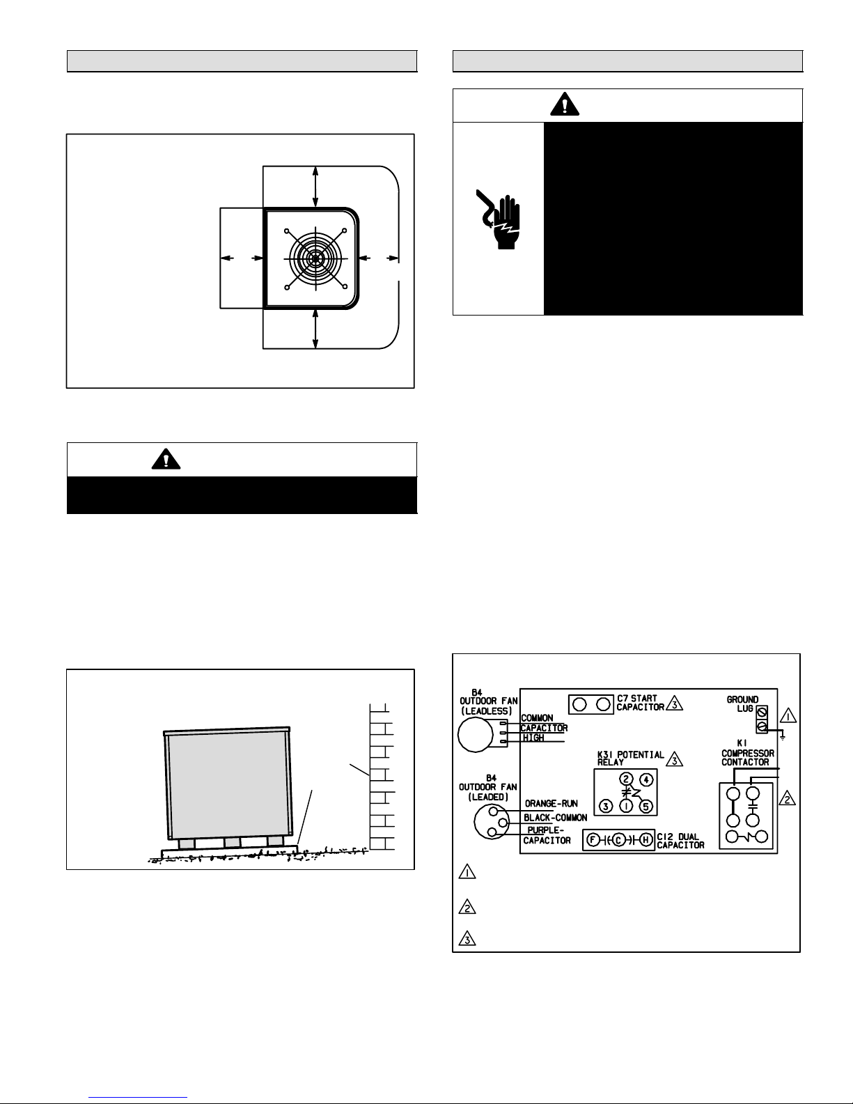
Setting the Unit
Refer to unit dimensions for sizing mounting slab, platforms or supports. See figure 1 for installation clearances.
Installation Clearances
NOTE − A service access
clearance of 30" (762 mm)
must be maintained in front
of the service access panel.
Clearance to one side must
be 36" (914 mm). Clearance
to one of the remaining two
sides may be 12" (304 mm)
and the final side may be 6"
(152 mm).
NOTE − A clearance of 24"
(610 mm) must be maintained between two units.
NOTE − 48" (1219 mm)
clearance required on top
of unit. Maximum soffit
overhang is 36" (914 mm).
30"
(762 mm)
AS NOTED
AS
NOTED
AS
NOTED
Figure 1
CAUTION
In order to avoid injury, take proper precaution when
lifting heavy objects.
Slab Mounting
When installing a unit at grade level, the top of the slab
should be high enough above the grade so that water from
higher ground would not collect around the unit. See figure
2. Slab may be level or have a slope tolerance away from
the building of not more than 2 degrees or 2 inches per 5
feet (51 mm per 1524 mm).
Electrical
WARNING
Electric Shock Hazard.
Can cause injury or death.
Unit must be grounded in accordance
with national and local codes.
Line voltage is present at all components when unit is not in operation on
units with single-pole contactors. Disconnect all remote electric power supplies before opening access panel.
Unit may have multiple power supplies.
In the U.S.A., wiring must conform with current local codes
and the current National Electric Code (NEC). In Canada,
wiring must conform with current local codes and the current
Canadian Electrical Code (CEC).
Refer to the furnace or blower coil installation instructions
for additional wiring application diagrams and refer to unit
nameplate for minimum circuit ampacity and maximum
overcurrent protection size.
1. Install line voltage power supply to unit from a properly
sized disconnect switch.
2. Ground unit at unit disconnect switch or to an earth
ground.
NOTE − Connect conduit to the unit using a proper
conduit fitting.
NOTE − Units are approved for use only with copper
conductors. 24V, Class II circuit connections are
made in the low voltage junction box. Refer to appropriate figure for field wiring. See figure 3 for field
wiring. See figures 4 and 3 for typical wiring.
Slab Mounting
INSTALL UNIT LEVEL OR, IF ON A SLOPE, MAINTAIN SLOPE
TOLERANCE OF 2 DEGREES (OR 2 INCHES PER 5 FEET [51 MM
PER 1.5 M]) AWAY FROM BUILDING STRUCTURE.
BUILDING
STRUCTURE
MOUNTING
SLAB
GROUND LEVEL
Figure 2
Roof Mounting
Install the unit a minimum of 6 inches (152 mm) above the
roof surface to avoid ice build−up around the unit. Locate
the unit above a load bearing wall or area of the roof that
can adequately support the unit. Consult local codes for
rooftop applications.
Page 3
Outdoor Unit Field Wiring Diagram
208/230/60/1
L2
L1
WARNING! − ELECTRIC SHOCK HAZARD. CAN CAUSE INJURY OR DEATH.
UNIT MUST BE GROUNDED IN ACCORDANCE WITH NATIONAL AND LOCAL
CODES.
NOTE − FOR USE WITH COPPER CONDUCTORS ONLY. REFER TO UNIT
RATING PLATE FOR MINIMUM CIRCUIT AMPACITY AND MAXIMUM
OVER-CURRENT PROTECTION SIZE.
NOTE − HARD START KIT IS REQUIRED ON −024 MODEL; OPTIONAL FOR
OTHER APPLICATIONS.
Figure 3
NOTE − A complete unit wiring diagram is located
inside the unit control box cover.
HSXA16 SERIES
3. Install room thermostat (ordered separately) on an in-
color coded, temperature
side wall approximately in the center of the conditioned
area and 5 feet (1.5 m) from the floor. It should not be
installed on an outside wall or where it can be affected
by sunlight, drafts or vibrations.
4. Install low voltage wiring from outdoor to indoor unit
and from thermostat to indoor unit.
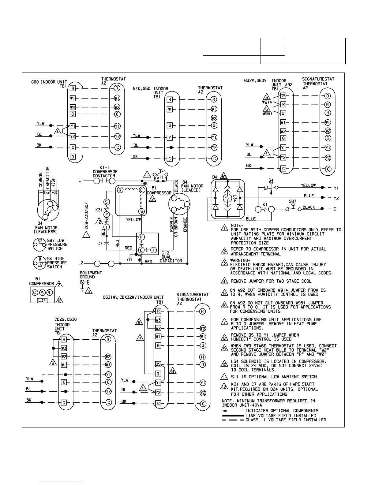
HSXA16 Wiring
NOTE − For proper voltages, select thermostat wire
gauge per the following chart:
Wire run length AWG # Insulation type
less than 100’ (30m) 18
more than 100’ (30m) 16
color−coded, temperature
rating 35ºC minimum
504953M 03/06
Figure 4
Page 4
Refrigerant Piping
024
3/8 in
7/8 in
3/8 in
7/8 in
L15 65
036
(10 mm)
(22 mm)
(10 mm)
(22 mm)
15 ft. 50 ft.
If the HSXA16 unit is being installed with a new indoor coil
and line set, the plumbing connections should be made as
outlined in this section. If an existing line set and/or indoor
coil is going to be used to complete the HSXA16 system,
refer to the following section which includes flushing procedures.
Field refrigerant piping consists of liquid and vapor lines
from the outdoor unit (sweat connections) to the indoor coil
(flare or sweat connections). Use Lennox L15 (sweat, nonflare) series line sets as shown in table 2 or use field-fabricated refrigerant lines. Valve sizes are listed in table 2.
Table 2
Refrigerant Line Sets
Field
Connections
Mod
el
−024 3/8 in. 7/8 in 3/8 in. 7/8 in L15−65
−036
−048
−060 3/8 in.
Liquid
Line
.
(10 mm)
(10 mm)
Vapor
Line
(22 mm)
1−1/8 in.
(29 mm)
Recommended Line Set
Liquid
Line
(10 mm)
3/8 in.
(10 mm)
.
Vapor
Line
(22 mm)
1−1/8 in.
(29 mm)
L15
Line Sets
15 ft. − 50 ft.
(4.6 m − 15 m)
Field
Fabricated
Installing Refrigerant Line
During the installation of any heat pump or a/c system, it is
important to properly isolate the refrigerant lines to prevent
unnecessary vibration. Line set contact with the structure
(wall, ceiling or floor) causes some objectionable noise
when vibration is translated into sound. As a result, more
energy or vibration can be expected. Closer attention to
line set isolation must be observed.
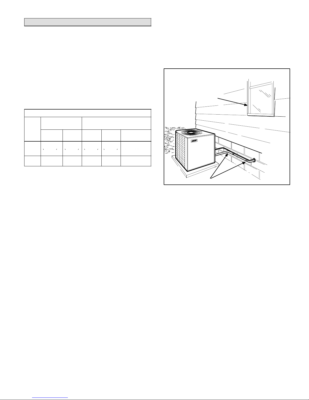
Outside Unit Placement and Installation
Install unit away
from windows and
neighbors’ windows
NOTE − When installing refrigerant lines, refer to Lennox
Refrigerant Piping Guide (Corp. 9351−L9) or Lennox
Technical Support Product Applications for assistance. In
addition, be sure to consider the following points:
Select line set diameters from table 2 to ensure that oil
returns to the compressor.
Units are designed for line sets of up to fifty feet (15 m);
for longer line sets, consult piping guidelines.
Size vertical vapor riser to maintain minimum velocity
at minimum capacity.
Refrigerant Line ConnectionsHSXA16
Matched with New Indoor Coil and Line Set
If an existing indoor coil that was equipped with an RFCI
metering device is being replaced, the liquid line must also
be replaced prior to the installation of the HSXA16 unit.
If refrigerant lines are routed through a wall, seal and isolate the opening so vibration is not transmitted to the building.
Two 90° elbows installed in line set will reduce line set vibration.
Figure 5
Following are some points to consider when placing and
installing a high−efficiency outdoor unit:
1. PlacementBe aware some localities are adopting
sound ordinances based on how noisy the unit is at the
neighbors’ home, not at the original installation. Install
the unit as far as possible from the property line. When
possible, do not install the unit directly outside a bedroom window. Glass has a very high level of sound
transmission. Figure 5 shows how to place the outdoor
unit and line set.
2. Line Set IsolationThe following illustrations dem-
onstrate procedures which ensure proper refrigerant
line set isolation. Figure 6 shows how to install line sets
on horizontal runs. Figure 7 shows how to make a transition from horizontal to vertical. Figure 8 shows how
to install line sets on vertical runs.
Page 5
HSXA16 SERIES
 Loading...